

Page 1
Installation Instructions for the
5
ISSUE 2
4AV Series Vane Sensors
PERSONAL INJURY
DO NOT USE these products as safety or
emergency stop devices or in any other application
where failure of the product could result in personal
injury.
Failure to comply with these instructions could
result in death or serious injury.
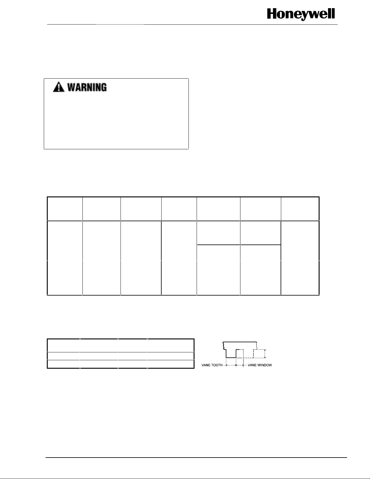
ELECTRICAL CHARACTERISTICS
Catalog
Listing
4AV15F 24 AWG Wire 5.50 ± 0.25
4AV16F 24 AWG Wire 7.45 ± 0.25
4AV17F 24 AWG Wire 13.15 ± 0.50
4AV18F 24 AWG Wire 18.15 ± 0.50
4AV19F 24 AWG Wire 22.00 ± 0.50
4AV20F . 015 X . 025 PCB 0.140
4AV20F-T1* .025 X .025
4AV20F-T2**
*Will mate with AMP Connector Housing 87499-8, not supplied
**Will mate with Molex Connector Housing 2695/6471, not supplied
Termination
Connector
.025 X .025
Connector
Lead
Length
AMP Terminal
Block 103323-4
Molex Terminal
Block 22-05-3041
Supply
Voltage
All Listings
4.5 VDC
through
26.5 VDC
PK 8760
GENERAL INFORMATION
4AV Hall effect vane sensor s in cl ude a Hal l effec t
sensor and a magnet in a common package. They
are operated by passing a ferrous vane through the
gap between the magnet and the sensor.
With no vane in the gap, the output is Operated
(conducting). With the vane in the gap, the output is
Released (non-conducting). The vane actuator is
annealed low carbon cold roll ed ste el , type AI SI
1018 or lower in carbon. Minimum recomm end ed
vane dimensions are required to ensure operating
characteristics will be met.
Supply
Current
All Listings
18.5 mA Max
@ -40 °C
15.25 mA typical
11.75 mA
@25 °C
typical
Output
Voltage
All listings
0.4 V Max
@125 °C
0.1 typical
0.075 V
@25 °C typical
Output
Sink Current
All listings
40 mA Max
Dual output
sink currents
are summed
to reach total.
VANE DIMENSIONS (mm/in)
Thickness Min.
Window
1,0/0.4 10,2/.40 10,2/.40 9,27/.365
1,6/.06 10,2/.40 6,3/.25 9,27/.365
Min.
Tooth
Min. Tooth
Depth
Sensing and Control
Page 2
4AV Series Vane Sensors
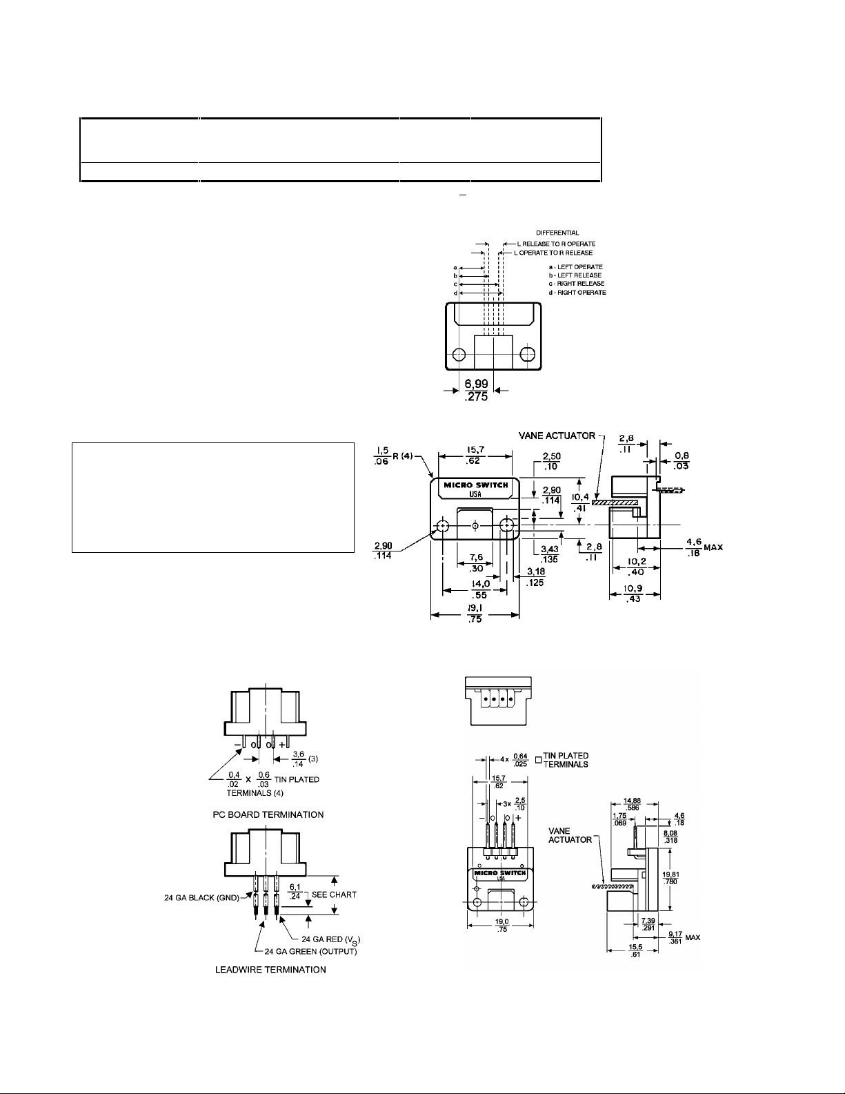
MECHANICAL CHARACTERISTICS (mm/in)
Series Left Left Left Right Right Right L-R
Operate Release Diff. Operate Release Diff Diff.
a b d c
4AV* 5,4/.213 6,0/.237 0,6/.024 8,6/.337 7,9/.313 0,6/.024 2,5/.100
*Operating characteristics of the 4AV are adjusted to produce a .100 + .010 dimension between
the Operate point on one side of the package to the Release point on the other side. The actuator
can be designed to produce a specific pulse width for timing or sequencing operations.
MOUNTING DIMENSIONS (for reference only)
ISSUE 2 PK 87605
CAUTION
PRODUCT DAMAGE
• Do not exceed electrical specifications.
• Do not mis-wire the output connection.
• Do not reverse supply voltage polarity.
• Handle terminals with care.
Failure to comply with these instructions may
result in product damage.
Mates with AMP housing 87499-8
2 Honeywell • Sensing and Control For application help: call 1-800-537-6945
Page 3

4AV Series Vane Sensors
ISSUE 2 PK 87605
SOLDERING
CAUTION
PRODUCT DAMAGE
• Ensure iron tip is clean when soldering.
Failure to comply with these instructions may result in
product damage.
Hand Soldering
The following is recommended:
Flux: Rosin Base
1.
Solder: Kester #44 60-40 rosin core, or
2.
equivalent.
Soldering Iron: Type; Weller, Model TC-552, 55
3.
watt or equivalent.
Tip Size: 3mm (.118 in.) Diameter x 30mm
4.
(1.182 in.) long
Tip Temperature: 288°C (550°F) max
5.
Terminal Contact Time: 6 second s max.
6.
Wave Soldering
The following is recommended:
Flux: London Chemical Co. Loncoflux - 106A35
1.
or equivalent
Preheat: Preheaters should be set to give 95 °C
2.
(200 °F) on the top (component side) of printed
circuit board just prior to board entering the
wave. (May have to be adjusted depending
upon board thickness.)
Solder Temperature: 260 °C (500 °F) max.;
3.
preferably 252 °C to 260 °C (485 °F to 500 °F).
Speed: Set conveyor speed to approximately
4.
4.5 feet/minute (1,37 meters/minute).
Printed circuit board requires rigid support
5.
during wave soldering.
CLEANING
Hand Cleaning
Clean areas with a 50-50 mixture of isopropyl
alcohol and clean tap water. Dry in a 71 °C (160 °F)
oven for 10-15 minutes, preferably in a noncirculating oven. This will remove all moisture from
the assembly, which must be done before electrical
testing, or application.
Machine Cleaning *
Detergent: London Chemical Company
Loncoterge 444-NRT6 or equivalent. Equipment:
Dee Electric Aqueous Cleaner or equivalent. The
following is reccommend ed:
Wash Section: 55 °C (130 °F) maxim um water
1.
temperature, 5 to 10% maximum solution soft
water, low pressure nozzles (60 psi) on top
spray and high pressure nozzles ( 120 psi) on
bottom spray, conveyor sp eed 3 feet/mi nute
minimum. Recirculating tank.
Rinse Section #1: Clean tap water up to 25
2.
grains hard, salt free (to minimize possibility of
corrosion), unheated, non-recirculating, with
high press ure nozzles (120 psi).
Rinse Section #2: Clean deion iz ed water onl y,
3.
high pressure nozzles (120 psi), unheated and
non-recirculating.
Air Knife Section: To remove excessive amounts
4.
of water.
Drying Section: 71°C (160 °F) drying for 10-15
5.
minutes, preferably in a non-circulating conveyor
oven.
* In this cleaning system, the detergent in the wash
section removes the non-polar contaminants, the first rinse
removes the detergent solution, and the deionized water
rinse removes the polar contaminants. The air knife and
dryer remove all the moisture from the assembly, which
must be done before electrical testing or application.
CAUTION
PRODUCT DAMAGE
• Ensure cleaner does not come in contact with sensor If
other cleaning methods are selected for removal of flux
residue.
Failure to comply with these instructions may result in
product damage.
For application help: call 1-800-537-6945 Honeywell • Sensing and Control 3
Page 4

4AV Series Vane Sensors
EXAMPLE WIRING DIAGRAMS
ISSUE 2 PK 87605
WARRANTY/REMEDY
Honeywell warrants goods of its manufacture as
being free of defective materials and fault y
workmanship. Contact your local sales office for
warranty information. If warranted goods are
returned to Honeywell during the period of coverage,
Honeywell will repair or replace without charge those
items it finds defective. The foregoing is Buyer’s sole
remedy and is in lieu of all other warranties,
expressed or implied, including those of
merchantability and fitness for a particular
purpose.
Specifications may change without notice. The
information we supply is believed to be accurate and
reliable as of this printing. However, we assume no
responsi bility for its use.
While we provide application assistance
personally, through our literature and the Honeywell
web site, it is up to the customer to determine the
suitability of the product in the application.
For application assistance, current specifications,
or name of the nearest Authorized Distributor,
contact a nearby sales office. Or call:
1-800-537-6945 USA
1-800-737-3360 Canada
1-815-235-6847 International
FAX
1-815-235-6545 USA
INTERNET
www.honeywell.com/sensing
info.sc@honeywell.com
Sensing and Control
Honeywell Inc.
11 West Spring Street
Freeport, Illinois 61032
Printed w ith S o y In k
on 50% Recycled Paper
PK 87605-2-EN IL50 GLO 0303 Printed in USA
www.honeywell.com/sensing
 Loading...