

Page 1
Construction
The refilling combination consists of:
• Shut off valve, up- and downstream
• Complete backflow preventer with discharge connection,
valve cartridge (incl. integrated check valve and discharge
valve, upstream), integrated strainer upstream (mesh size
approx. 0,5 mm) and check valve downstream
• Complete pressure reducing valve with valve insert, spring
hood (including adjuster knob), setpoint spring and pressure
gauge
Materials
• Dezincification-resistant brass housing
• Discharge connection, valve cartridge, valve insert and spring
hood in high-grade synthetic material
• High-grade synthetic material check valve
•Seals in NBR
• Spring steel adjustment spring
• Isolation shell in EPP
EN0H-1548GE23 R0709 • Subject to change
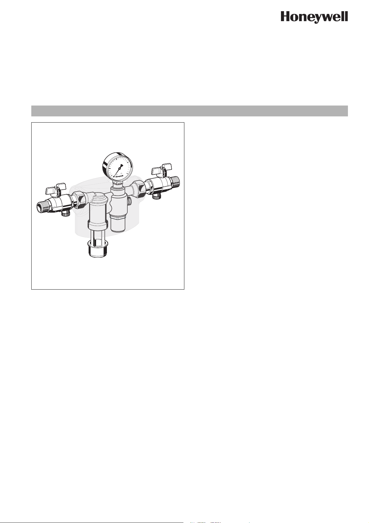
NK295C
Refilling combination
Compact construction
Product specification sheet
Application
The refilling combination serves filling and refilling of closed
heating systems to DIN EN 12828:2003.
It can be connected in accordance to EN 1717 constantly with
the drinking water supply.
The refilling combination combines backflow preventer, pressure
reducing valve and two ball valves in one appliance.
All devices for refilling a heating installation according to conforming standards are contained.
Special Features
• Compact construction
• Constant connection with the drinking water supply in accordance with EN1717 by hose line or piping is possible
• Corrosion resistant by use of brass and stainless steel
• Low pressure loss and high flow rate
• Optimal protection of the drinking water supply system
• Triple security - two check valves and a discharge valve separate the backflow preventer into three pressure zones
• Field-tested reliable pressure reducing valve
• Pressure reducing valve with inlet pressure balancing - inlet
pressure fluctuation does not influence the outlet pressure
• Outlet pressure adjustable and directly at the pressure gauge
readable
• DIN/DVGW approved check valve
• Variable connection options to the heating system
• Low maintenance effort
• Meets KTW recommendations for potable water
Range of Application
Medium Water without inhibitors
Inlet pressure min. 1.5 bar max. 10.0 bar
Outlet pressure 1.5-6 bar
Liquid category
Backflow Preventer
Technical Data
Installation position horizontal pipework with discharge
Operating temperature max. 65°C
Connection size
Discharge
Connection size 1/2" AG
3 (slightly toxic materials)
connection directed downwards
HT 40
www.honeywell.com 1
Page 2
NK295C Refilling combination
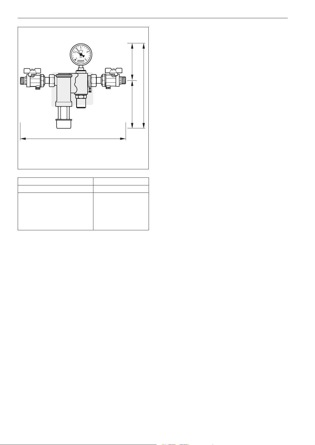
L
Connection size R 1/2"
Weight approx. kg 1.4
Dimensions mm
H 216
h
1
h
2
L 318
87.6
128
Method of Operation
The refilling combination combines backflow preventer, pressure
reducing valve and ball valves in one appliance.
The backflow preventer is a safety device in accordance with EN
1717 to protect systems against back pressure, back flow and
h1
back syphonage of non-potable water into service pipe, plants
and equipments.
The backflow preventer is separated in three chambers (inlet,
middle and outlet chamber).
H
If no water is drawn from the downstream system, the backflow
preventer is in normal position. The up- and downstream check
h2
valves and the discharge valve are closed.
If water is drawn from the downstream system, the backflow
preventer is in flow position. The check valves up- and downstream are opened and the discharge valve is closed.
If the differential pressure between middle and inlet chambers is
less than 10 % of the inlet pressure, the system disconnector
moves into disconnect position (back suction). The inlet side
backflow preventer closes and the discharge valve opens.
There is no possibility to control the safety function by measuring.
The pressure reducing valve reduces the pressure on the inlet
side (admission pressure) to the level of the desired pressure on
the outlet side (outlet pressure) in individual cases.
Spring-loaded pressure reducing valves work according to a
system of force balance. The piston force works against the
spring force of the control valve. If the outlet pressure (back pressure) drops as a consequence of drawing water, leading to the
piston force dropping as well, the now greater spring force will
open the valve. The outlet pressure is higher again until the
balance between piston and spring force is once again achieved.
The inlet pressure has no influence in either opening or closing of
the valve. Because of this, inlet pressure fluctuation does not
influence the outlet pressure, thus providing inlet pressure balancing.
Options
NK295C-1/2A = Standard version with threaded connection
R1/2"
2 www.honeywell.com
EN0H-1548GE23 R0709 • Subject to change
Page 3

Installation Example
NK295C Refilling combination
Installation Guidelines
• Install in horizontal pipework with discharge connection
directed downwards
• The installation may not take place in areas or ducts where
poisonous gases or vapours may be present or where flooding can occur
• The installation location must be ventilated well
• The installation location should be protected against frost
and be easily accessible
o Simplified maintenance and cleaning
o Pressure gauge at the pressure reducing valve can be read
off easily
• Provide a straight section of pipework of at least five times the
nominal valve size after the pressure reducing valve (in accordance with DIN 1988, Part 5)
• The refilling combination has an integrated strainer - no separate strainer necessary
o Refilling combination is protected against malfunction and
corrosion damage resulting from ingress of foreign bodies,
e.g. welding beads, sealing materials, metal cuttings and
rust
Typical Applications
The refilling combination is priority suitable for domestic drinking
water supply.
The refilling combination can be used for commercial and industrial applications in consideration of its specifications.
Below two typical applications:
• Automatic refilling of the heating system
• Automatic refilling of system up to liquid catgory 3 in accordance with DIN EN 1717
EN0H-1548GE23 R0709 • Subject to change
www.honeywell.com 3
Page 4

NK295C Refilling combination
Automation and Control Solutions
Honeywell GmbH
Hardhofweg
D-74821 Mosbach
Phone: (49) 6261 810
Fax: (49) 6261 81309
http://europe.hbc.honeywell.com
www.honeywell.com
Manufactured for and on behalf of the
Environmental and Combustion Controls Division
of Honeywell Technologies Sàrl, Rolle, Z.A. La
Pièce 16, Switzerland by its Authorised Representative Honeywell GmbH
EN0H-1548GE23 R0709
Subject to change without notice
© 2009 Honeywell GmbH
Page 5

NK295C Refilling combination
EN0H-1548GE23 R0709 • Subject to change
www.honeywell.com 5
Page 6

NK295C Refilling combination
EN0H-1548GE23 R0709 • Subject to change
www.honeywell.com 6
 Loading...