

Page 1

Installation Instructions for the
MICRO SWITCH NGC Series
Compact Limit Switches
m WARNING
PERSONAL INJURY
DO NOT USE these products as safety or emergency stop
devices or in any other application where failure of the
product could result in personal injury.
Failure to comply with these instructions could result in
death or serious injury.
ROUTINE MAINTENANCE
It is important to appreciate that the safe operation of your
machine will depend upon the safe efficient working of all components and devices, which would include these switches. It is
essential that a regular maintenance routine for the machine
is established and that the routine should specifically cover all
components that interface with these switches. It is imperative
that any wear on the actuator mechanism operating the switch,
or on the switch itself, and also any drift in the operating characteristics are identified at an early stage and the necessary
corrective actions implemented by the end user, thus ensuring
operator safety.
Periodic maintenance of the switch and replacement at appropriate intervals will avoid failures due to wear. The frequency
of the maintenance will be determined by the type of machinery and is the responsibility of the machine manufacturer or
end user. The switch actuator must not be traveled to the point
where it reaches its physical end stop, or beyond, as damage
could occur. It is good design practice not to hold the switch
actuator in the overtravel position for extended periods, that
the actuator moves freely without jamming during operation
and that the alignment of the machine actuator to the switch
prevents damage or excessive wear. The electrical operation of
the switch must be checked and tested at regular intervals only
by a suitably qualified person.
Issue 7
32313117
m ATTENTION
BLESSURES CORPORELLES
NE PAS UTILISER ces produits en tant que dispositifs d’arrêt
d’urgence ou de sécurité, ni dans aucune autre application
où la défaillance du produit pourrait entraîner des blessures
corporelles.
L’inobservation de ces instructions peut entraîner la mort
ou de graves blessures.
ENTRETIEN COURANT
Il est important de se rappeler que le bon fonctionnement de
votre machine dépendra de l’usage correct de tous les composants et dispositifs y compris des interrupteurs de fin de
course. Un entretien régulier de la machine est essentiel et doit
être établi, cet entretien doit couvrir tous les composants qui
interactent avec ces interrupteurs. Il est impératif que toute
usure du mécanisme de l’actionneur opérant l’interrupteur, ou
l’usure de l’interrupteur lui-même, ou encore toute variation
des caractéristiques de fonctionnement, soit identifiée le plus
tôt possible et que les mesures correctives nécessaires soient
prises par l’utilisateur, assurant ainsi la sécurité de l’opérateur.
L’entretien régulier de l’interrupteur et son remplacement à
des intervalles appropriés évitera les pannes dues à l’usure. La
fréquence d’entretien est déterminée par le type de machine
et est la responsabilité du fabricant ou de l’utilisateur de la
machine. L’actionneur du fin de course ne doit pas être déplacé
au-delà du point où il atteint sa propre butée pour éviter de
l’endommager. Il est préférable de ne pas maintenir l’actionneur
de l’interrupteur en position de surcourse pendant des périodes
prolongées. Durant le fonctionnement, l’actionneur doit pouvoir
se déplacer librement sans se coincer et son alignement avec
l’interrupteur doit empêcher les risques d’endommagement
ou d’usure excessive. Le fonctionnement du fin de course sous
tension doit être vérifié et testé à des intervalles réguliers par
du personnel qualifié uniquement.
Sensing and Internet of Things
Page 2

MICRO SWITCH NGC Series
m WARNUNG
PERSONENSCHADEN
Diese Produkte dürfen weder als Sicherheits-oder NotAbschaltgeräte noch in anderen Anwendungen, bei denen
ein Fehler an diesem Produkt zu Personenschaden führen
könnte, eingesetzt werden.
Missachtung dieser Anweisungen kann zu schweren
Verletzungen oder zum Tod führen.
ROUTINEWARTUNG
Es muß betont werden, daß der sichere Betrieb ihrer Maschine
vom sicheren und wirksamen Betrieb aller Komponenten und
Vorrichtungen abhängt, zu denen auch diese Schalter gehören.
Besonders wichtig ist es, eine regelmäßige Wartungsroutine für
die Maschine einzurichten, die insbesondere alle Komponenten
mit berücksichtigt, die in Verbindung mit diesen Schaltern
verwendet werden. Verschleißerscheinungen am Betätigungsmechanismus des Schalters oder am Schalter selbst, sowie
jede Veränderung der SchaltbetätigungsKenndaten, müssen
unbedingt bereits im Anfangsstadium erkannt und vom Endnutzer behoben werden, um die Sicherheit des Bedienenden zu
gewährleisten.
Durch regelmäßige Wartung des Schalters und Auswechseln
in angemessenen Zeitabständen werden Störungen infolge
von Abnutzung vermieden. Das Wartungsintervall richtet sich
nach der Art der Maschine und liegt in der Verantwortung des
Herstellers oder Endnutzers. Um Schäden zu vermeiden, darf
der Schalterbetätiger nicht bis zum Endanschlag oder darüber
hinaus ausgefahren werden. Der Einbau des Schalters muß
so ausgeführt werden, daß der Schalterbetätiger nicht über
einen längeren Zeitraum hinweg in Nachlaufwegsposition
betätigt wird, und er sollte sich leicht bewegen lassen, ohne
beim Betätigen zu klemmen. Die Ausrichtung des Maschinenbetätigers mit dem Schalter soll der Vorbeugung gegen
Schäden oder übermäßige Abnutzung dienen. Der elektrische
Betrieb des Schalters muß geprüft und in regelmäßigen Zeitabständen von einer entsprechend qualifizierten Person getestet
werden.
ISSUE 7 32313117
2 sensing.honeywell.com
Page 3

MICRO SWITCH NGC Series
ISSUE 7 32313117
Conforming to
standards
Ultilization
category
Thermal current
Rated Insulation
voltage (Ui)
Rated impulse
withstand
voltage (Uimp)
Pollution degree
Operating
temperature
Mechanical life
Electrical life
Degree of
protection
Min. actuation
speed
Max. actuation
speed
Max. actuation
frequency
Shock Choc Stossfestigkeit
Vibration Vibration Vibrationfestigkeit
Allowable panel
thickness
Mounting holes
Tightening
torque
Conforme aux
standards
Catégoire
d’utilisation
Courant
permanent
maximum (Ith)
Tension
efficace (Ui)R
Tension
d’isolment
(Uimp)
Degré de
pollution
Température de
foncionnment
Durée de vie
mécanique
Durée de vie
électrique
Indice de
protection
Vitesse min. de
la clé
Vitesse max. de
la clé
Fréquence
max. de
pénétration
Epaisseur
de panneau
autorisée
Trous de
montage
Couple de
serrage
Entspricht den Normen
Verwendungskategorie
Dauerstromt (Ith)
Nennisolationsspannung (Ui)
Max.ImpulsPrufspannung
(Uimp)
Verschmutzungsgrad 3 (III)
Betriebstamperatur
Mechanische Lebensdauer
Elektrisches Lebensdauer
Schutzart NEMA 1, 4, 12, 13; IP67 per IEC 60529
Min.
Betaetigungsgeschwindigkeit
Max.
Betaetigungsgeschwindigkeit
Max. Betaetigungsfrequenzt
Zulässige Tafeldicke 7,0 mm [0.28 in] max.
Befestigungslöcher M4 or #8 screws
Anzugsmoment 1,5 Nm to 2,0 Nm [13.27 in-lb to 17.7 in-lb]
IEC 6094751, IEC 61373,
EN455452 HL 3 (metal variants with M12 connectors only)
A300 AC15: 120 V 6 A; 240 V 3 A per
1NC/1NO (silveralloy contacts)
1NC/1NO (goldplated contacts)
2NC/2NO (silveralloy contacts)
2NC/2NO (goldplated contacts)
1NC/1NO: 10 A
2NC/2NO: 5 A
1NC/1NO: 400 V as per IEC 6094751
2NC/2NO: 250 V as per IEC 6094751
1NC/1NO: 2500 V as per IEC 6094751
2NC/2NO: 1500 V as per IEC 6094751
25 °C to 75 °C [13 °F to 167 °F]
(for extended operating temperature options, see Table 3)
1NC/1NO: 5 M cycles min at 120 CPM
2NC/2NO: 5 M cycles min at 60 CPM
1 A, 110 Vdc, 500,000 cycles only for NC circuit
10 mA, 30 Vdc, 50,000 cycles only for gold-plated contacts
0,3 mm/s
2 m/s
1NO/1NC: 120 cpm
2NO/2NC: 60 cpm
50 g for 11 ms as per IEC 60068227; railway application,
per IEC 61373 Class I Car B type
10 G as per IEC6006826; Railway application
per IEC61373 Class I Car B type
IEC 6094751 and UL 508
Q300 DC13: 125 Vdc 0.55 A; 250 Vdc
0.27 A per IEC 6094751 an UL 508
low level current: 30 mVdc 10 mA
resistive
C300 AC15: 0.75 A 240 Vac per IEC
6094751
R300 DC13: 0.1 A 250 Vdc per IEC
6094751
low level current: 30 mVdc 10 mA
resistive
Sensing and Internet of Things 3
Page 4
MICRO SWITCH NGC Series
Medium-Dut
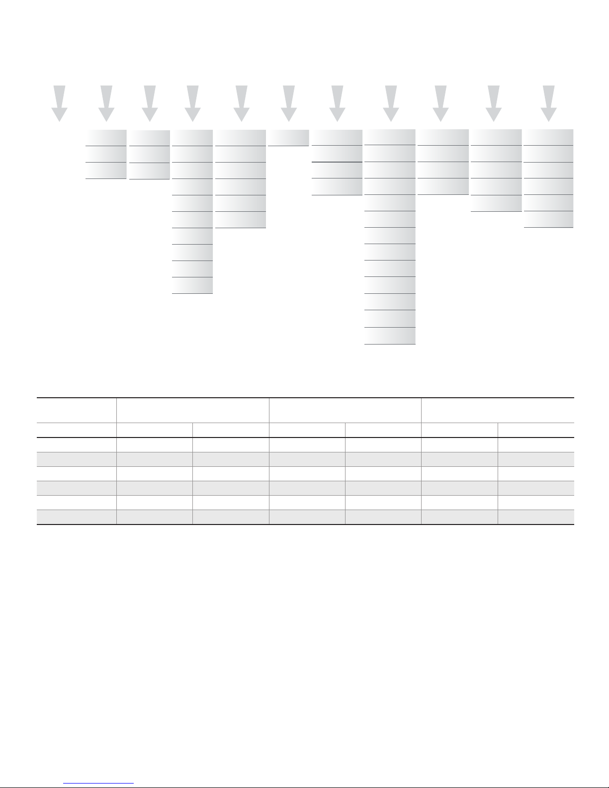
Figure 1. Product Nomenclature and Order Guide
ISSUE 7 32313117
NGC
Switch Type
NGC Series
Compact
Limit Switch
M
Housing
Metal
M
y
Plastic
P
Plastic with
mounting
Q
ring support
NOTE: not all combinations
of model code are available.
Please contact your Honeywell
provider/representative for assistance.
1
Only applicable for head type “A”
2
Only applicable for lever types “1, 2, 6” and switch types “01” and “07”
3
Only applicable for lever types “2, 6”
4
Only applicable for metal housing Type “M”
5
Typically applicable for plastic housing Type “P” and “Q”, and without grounding metal housing Type “M”
6
Only applicable for switch type “01” and “07”
7
Cable meets EN 50306, but does not meet with UL requirement
8
Only applicable for “O0” cable length. Not applicable to switch types “24” and “32”
9
“00” cable length is not applicable for connector/cable exit type “A”, “B”, “D”, and “R”. Not applicable to switch types “24” and “32”
10
DIN 5510-2-2009 does not apply to NGC variant with suffix modification code “H85”. Also applicable only for connector/cable types “B”, “R”, “N”, and “P”. See table 2
11
Modification code “L40” is a -40 °C variant. Only applicable to connector/cable types “B”, “R”, “N”, and “P”. See table 2
A
Connection
Side exit,
A
right
Bottom
B
exit
Side exit,
C
left
02
Cable Length
No cable.
Internal
00
connector
0,25 m
02
[0.82 ft]
0,5 m
05
[1.64 ft]
0,7 m
07
[2.3 ft]
1,0 m
10
[3.28 ft]
1,5 m
15
[4.92 ft]
2,0 m
20
[6.56 ft]
3,0 m
30
[9.84 ft]
4,0 m
40
[13.12 ft]
5,0 m
50
[16.4 ft]
A
Connector/Cable
Exiting Housing
Standard cable
A
Halogen-free
B
cable
PUR cable
D
M12 4-pin
micro change,
N
P
R
dc connector
M12 5-pin
micro change,
dc connector
Railway cable
5,6,8
4,6,8
Connector at
End of Cable
X
7
X
None
01
Switch Type
1NC/1NO
snap action
01
silver contacts
1NC/1NO
snap action
07
gold contacts
2NC/2NO
snap action
24
silver contacts
2NC/2NO
snap action
32
gold contacts
Head Type
Side rotary
A
Pin plunger
B
Roller
C
plunger
Long pin
D
plunger
Top roller
J
lever arm
Cross roller
L
plunger
Pin plunger w/
M
boot seal
Panel-mount
N
pin plunger
Panel-mount
P
roller plunger
Panel-mount
cross-roller
Q
plunger
Panel-mount
pin plunger w/
R
boot seal
Long roller
S
plunger
Long
cross-roller
T
plunger
A
1
Levers
(Optional)
None
Standard,
1
fixed length
Adjustable
length,
2
roller lever
Short,
6
fixed length
1
1
1
1
Rollers
(Optional)
None
18 mm nylon
A
roller
18 mm
stainless steel
B
roller
18 mm nylon
C
roller, reversed
18 mm
stainless steel
D
roller, reversed
Modifications
Side rotary
lever,
M01
90° right
Side rotary
3
3
M02
M07
M08
H85
L40
lever,
90° left
Side rotary
short lever,
45° right
Side rotary
short lever,
45° left
High temp
variant,
10
85 °C
Low temp
variant,
11
-40 °C
2
2
Table 2. Connector/Cable Type Temperature Options
Connector/Cable
type
Standard NGC Series
(with modification code, none)
10, 11
High Temp NGC Series
(with modification code, H85)
Low Temp NGC Series
(with modification code, L40)
Tmin Tmax Tmin Tmax Tmin Tmax
A 25 °C 75 °C – – – –
B 25 °C 75 °C 25 °C 85 °C 40 °C 75 °C
D 25 °C 75 °C – – – –
R 25 °C 75 °C 25 °C 85 °C 40 °C 75 °C
N 25 °C 75 °C 25 °C 85 °C 40 °C 75 °C
P 25 °C 75 °C 25 °C 85 °C 40 °C 75 °C
4 sensing.honeywell.com
Page 5
MICRO SWITCH NGC Series
(Cable Length)
Type A1A/A1B • Side Rotary
Ø 18
[Ø 0.71]
PT
PT
FP
7 [0.28]
32,5 [1.28]
16,7 [0.66]
67,4 [2.65]
55,8 [2.2]
40,8
[1.6]
65,5 [2.58]
20 [0.79]
30 [1.19]
Ø 18
[Ø 0.71]
PT
PT
FP
7 [0.28]
19,9 [0.78]
67,4 [2.65]
55,8 [2.2]
40,8
[1.6]
20 [0.79]
30 [1.19]
Type A6A/A6B • Side Rotary (Short)
16,7
[0.66]
52 [2.05]
FP
67,4 [2.65]
Adjustable Length Roller Lever
103 [4.05] max.
20 [0.79]
30 [1.19]
Type A6C/A6D • Reversed Side Rotary (Short)
67,4 [2.65]
55,8 [2.2]
40,8
[1.6]
16,7
[0.66]
Ø 18
[Ø 0.71]
PT
PT
FP
7 [0.28]
10,8 [0.43]
52 [2.05]
Adjustable Length Roller Lever
67,4 [2.65]
FP
103 [4.05] max.
ISSUE 7 32313117
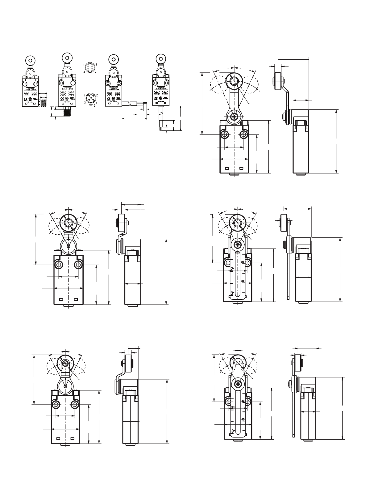
Figure 2. Connector Dimensions and PinOut Identification
4-Pin
Identification
15 [0.59]
12 [0.47]
B ±2
A ±5
L
A ±5
B ±2
Bottom Exit
Side Exit
17 [0.67]
12
[0.47]
Bottom Exit
5-Pin
Identification
Side Exit
(Cable Length)
NOTE: Connector option only available for SPDT versions.
Figure 3. Side Rotary A1A/A1B Dimensions
L
Figure 5. Side Rotary A2A/A2B DimensionsFigure 4. Side Rotary A6A/A6B Dimensions
PT
PT
29 [1.14]
7 [0.28]
51 [2.00] min.
20 [0.79]
30 [1.19]
Figure 7. Side Rotary A2C/A2D DimensionsFigure 6. Side Rotary A6C/A6D Dimensions
51 [2.00] min.
20 [0.79]
30 [1.19]
Ø 18
[Ø 0.71]
55,8 [2.2]
16,7
40,8
[0.66]
[1.6]
Type A2A/A2B • Side Rotary with
PT
PT
55,8 [2.2]
40,8
[1.6]
7 [0.28]
19,6 [0.77]
16,7
[0.66]
Type A2C/A2D • Reversed Side Rotary with
Sensing and Internet of Things 5
Page 6
MICRO SWITCH NGC Series
Black/
White
Black
Blue
Brown
Zb
2221
13
14
21-2
0° 25° 45° 65°
13-1
21-2
13-1
22
1
14
34
Green/Yellow
Violet
Black
2 Zb
0° 26.5° 45° 65°
Positive Opening
Orange-Blue
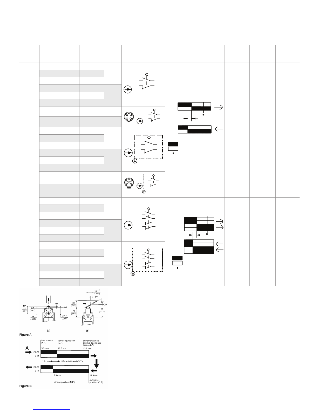
Table 3. Side Rotary Operating Characteristics
ISSUE 7 32313117
Actuation Catalog Listing
NGCP*****X01A** A
NGCP*****X01A** B
NGCP*****X01A** D
NGCP*****X07A** A
NGCP*****X07A** D
NGCP*****X01A** N 01
NGCP*****X07A** N 07
NGCM*****X01A** A
NGCM*****X01A** B
NGCM*****X01A** D
NGCM*****X07A** A
NGCM*****X07A** B
Side
Rotary
NGCM*****X07A** D
NGCM*****X01A** P 01
NGCM*****X07A** P 07
Connector/
Cable Exit
Switch
Type
01
07NGCP*****X07A** B
01
07
Circuit Diagram Bar Charts
2
4
4
2
22
2
DT
2
4
Contact Closed
Contact Open
Positive Opening
1
3 4
5
2
Blue
13
21
Black
White
2
3
13
21
1
Zb
Brown
Black
Zb
3
13
21
1
Zb
Green/Yellow
14
22
4
14
Differential
Travel max.
15°
Operat-
ing Force/
Torque max.
18 Ncm
[1.59 in-lb]
Release
Force/
Torque max.
2,5 Ncm
[0.22
in-lb]
NGCP*****X24A** A
NGCP*****X24A** B
NGCP*****X24A** D
NGCP*****X32A** A
NGCP*****X32A** D
NGCM*****X24A** A
NGCM*****X24A** B
NGCM*****X24A** D
NGCM*****X32A** A
NGCM*****X32A** D
6 sensing.honeywell.com
24
32NGCP*****X32A** B
24
32NGCM*****X32A** B
Orange
Brown
Gray
White
Orange
Brown
Gray
White
Green/Yellow
2 Zb
Blue
Red
Blue
Red
Black
Violet
White-Violet
Gray-Black
Brown-Red
Orange-Blue
White-Violet
Gray-Black
Brown-Red
DT
Contact Closed
Contact Open
16.5°
17 Ncm
[1.5 in-lb]
2,1 Ncm
[0.19
in-lb]
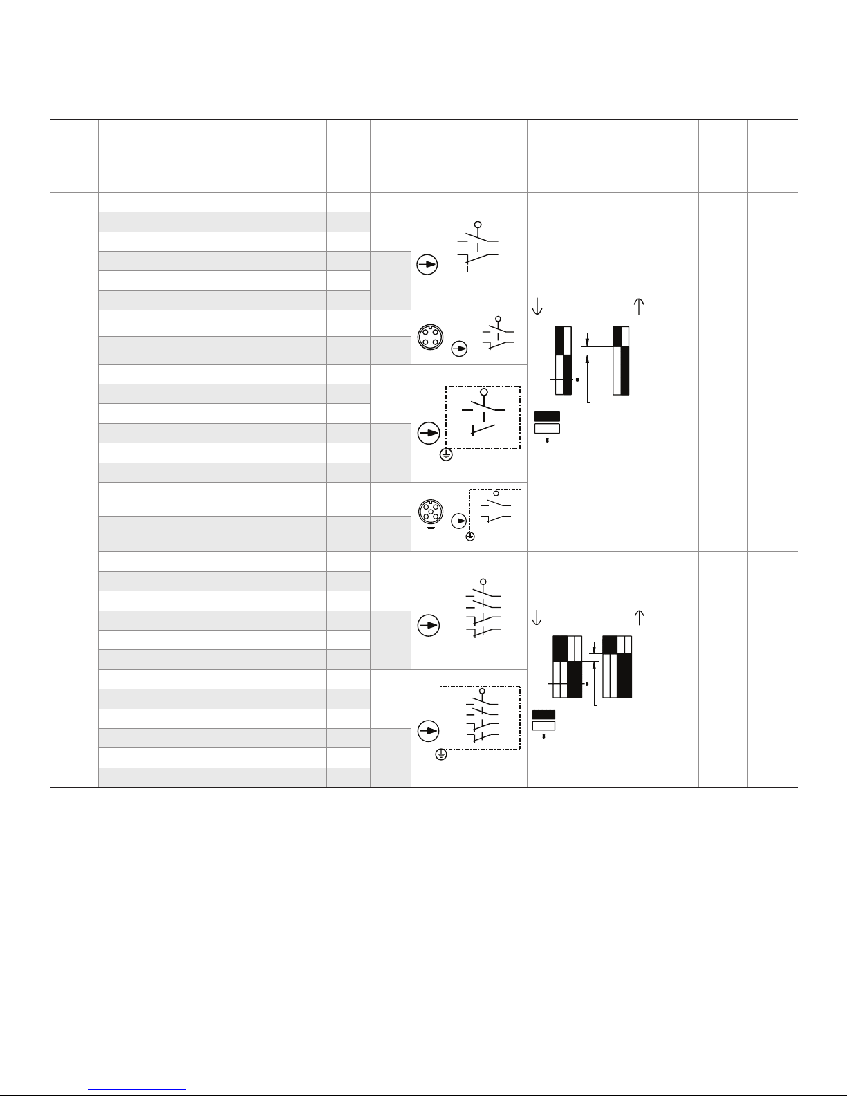
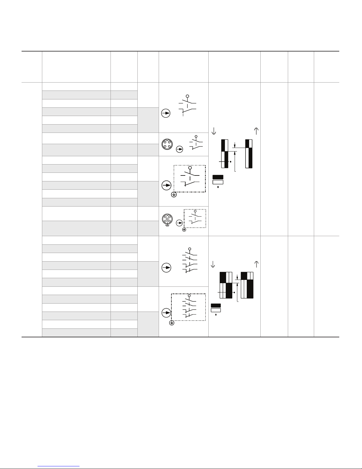
How to read and understand the bar chart information
The following example relates to a unit which has a snap action basic and which has a roller
pin plunger actuator. Follow the black arrows and the black strip on the chart. The black strip
indicates that there is a circuit between the terminals whose numbers are shown on the left and
when white there is no circuit.
Look at Figures A and B as examples. Actuator type used for test is the linear Cam travel type
(b) shown left. The start point is at the arrow marked ‘‘A’’ (See fig. B). This shows the free position to be 5.3 mm from the vertical center line of the unit. At this stage there is a circuit between
the terminals 2122 but no circuit between terminals 1314. The unit can be actuated until it
reaches the operating position which is 10,5 mm from the center line – a travel distance of 10,5
– 5,3 = 5,2 mm from the free position. At this point the circuit arrangement changes – no circuit
between 2122 but making a circuit between 1314. If, however, the contacts of terminals 2122
weld together and will not separate, a mechanical safety feature will take effect if the switch is
travelled past the point from which positive opening is assured, 13,9 mm. As the switch returns
it reaches the release position at 8.9 mm from the center line. The circuit will change back to the
original state and the difference between the operating position and the release position gives
what is known as the differential travel i.e. 10,5 – 8,9 = 1,6 mm. The asterisk (*) indicates the
point from which the positive opening is assured.
Page 7
MICRO SWITCH NGC Series
Pin Plunger
Ø 8
]
2X Ø4,3 thru.
2X Ø8 3,9
Roller Plunger
Ø 12,7 x 4
PT 2,1 [0.08]
2X Ø4,3 thru.
2X Ø8 3,9
Cross Roller Plunger
4 [0.16]
PT 2,1 [0.08]
2X Ø4,3 thru.
2X Ø8 3,9
Pin Plunger with Boot Seal
PT 2,1 [0.08]
2X Ø4,3 thru.
2X Ø8 3,9
Panel-Mount Pin Plunger
Ø 8
PT 2,1 [0.08]
2X Ø4,3 thru.
2X Ø8 3,9
Panel-Mount Roller Plunger
PT 2,1 [0.08]
Ø 12,7 x 4
2X Ø4,3 thru.
2X Ø8 3,9
Panel-Mount Cross Roller Plunger
Ø 12,7
4 [0.16]
PT 2,1 [0.08]
2X Ø4,3 thru.
2X Ø8 3,9
with Boot Seal
PT 2,1 [0.08]
Top Roller Lever Arm
40,8
[1.6]
55,8 [2.2]
6,8
[1.26]
ISSUE 7 32313117
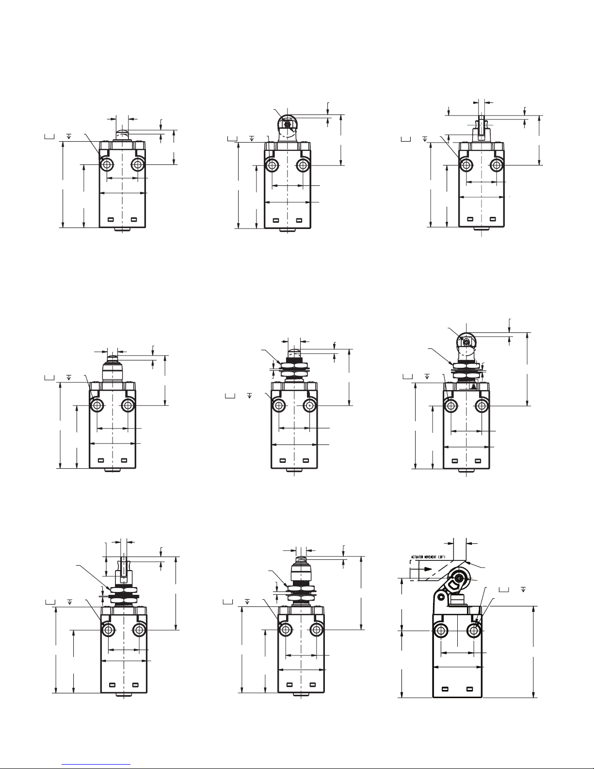
Figure 8. Pin Plunger B & D
Dimensions
PT 2,1 [0.08
FP ±0,5
20 [0.79]
30 [1.19]
55,8 [2.2]
[Ø 0.31]
40,8
[1.6]
NGC_B | FP 19,8 mm
NGC_D | FP 22,4 mm
Figure 11. Pin Plunger with Boot Seal
M Dimensions
Ø 6,7
[Ø 0.26]
32,3 [1.27]
Figure 9. Roller Plunger C & S
Dimensions
[Ø 0.5 x 0.16]
FP ±0,5
55,8 [2.2]
40,8
[1.6]
20 [0.79]
30 [1.19]
NGC_C | FP 30,3 mm
NGC_S | FP 32,85 mm
Figure 12. PanelMount Pin Plunger
N Dimensions
[Ø 0.31]
M12 x 1
7,0 [0.28] max.
36,5 [1.44]
Figure 10. Cross Roller Plunger L & T
Dimensions
Ø 12,7
[Ø 0.5]
FP ±0,5
55,8 [2.2]
40,8
[1.6]
20 [0.79]
30 [1.19]
NGC_L | FP 30,3 mm
NGC_T | FP 32,85 mm
Figure 13. PanelMount Roller
Plunger P Dimensions
[Ø 0.5 x 0.16]
M12 x 1
7,0 [0.28]
max.
47,5 [1.87]
Figure 14. PanelMount Cross Roller
Plunger Q Dimensions
55,8 [2.2]
55,8 [2.2]
40,8
[1.6]
M12 x 1
7,0 [0.28] max.
40,8
[1.6]
[Ø 0.5]
NGC_M
NGC_Q
20 [0.79]
30 [1.19]
47,5 [1.87]
20 [0.79]
30 [1.19]
20 [0.79]
30 [1.19]
NGC_N
55,8 [2.2]
40,8
[1.6]
20 [0.79]
30 [1.19]
NGC_P
Figure 16. Top Roller Lever Arm
Figure 15. PanelMount Pin Plunger
J Dimensions
With Boot Seal R Dimensions
Ø 6,7
[Ø 0.26]
M12 x 1
7,0 [0.28] max.
2X Ø4,3 thru.
2X Ø8 3,9
55,8 [2.2]
40,8
[1.6]
47,5 [1.87]
20 [0.79]
30 [1.19]
32
NGC_R
Panel-Mount Pin Plunger
[0.265]
Operating Position
Ø 14 x 5
2X Ø8 3,9
2X Ø4,3 thru.
20 [0.79]
30 [1.19]
NGC_J
Sensing and Internet of Things 7
Page 8
MICRO SWITCH NGC Series
Black/
White
Black
Blue
Brown
Zb
2221
13
14
Positive Opening
22
1
14
34
Green/Yellow
Violet
Black
2 Zb
Positive Opening
Table 4. Plunger Operating Characteristics
ISSUE 7 32313117
Actua-
tion
Plung-
er
Head
Con-
Catalog Listing
nector/
Cable
Switch
Type
Exit
NGCP*****X01 B/C/D/L/M/N/P/Q/R/S/T A
NGCP*****X01 B/C/D/L/M/N/P/Q/R/S/T B
01
NGCP*****X01 B/C/D/L/M/N/P/Q/R/S/T D
NGCP*****X07 B/C/D/L/M/N/P/Q/R/S/T A
07NGCP*****X07 B/C/D/L/M/N/P/Q/R/S/T B
NGCP*****X07 B/C/D/L/M/N/P/Q/R/S/T D
NGCP*****X01 B/C/D/L/M/N/P/Q/R/S/T N 01
NGCP*****X07 B/C/D/L/M/N/P/Q/R/S/T N 07
NGCM*****X01 B/C/D/L/M/N/P/Q/R/S/T A
NGCM*****X01 B/C/D/L/M/N/P/Q/R/S/T B
NGCM*****X01
B/C/D/L/M/N/P/Q/R/S/T
01
D
NGCM*****X07 B/C/D/L/M/N/P/Q/R/S/T A
07NGCM*****X07 B/C/D/L/M/N/P/Q/R/S/T B
NGCM*****X07
B/C/D/L/M/N/P/Q/R/S/T
D
NGCM*****X01 B/C/D/L/M/N/P/Q/R/S/T P 01
NGCP*****X07 B/C/D/L/M/N/P/Q/R/S/T P 07
Circuit Diagram Bar Charts
1
3 4
5
2
Blue
13
21
Black
White
2
3
13
21
1
3
13
21
1
Zb
Brown
Black
Zb
Zb
Green/Yellow
14
22
4
0
2
2,1
4,0
4,9
4
14
22
2
21-22
13-14
DT
Contact Closed
Contact Open
21-22
13-14
Dif-
ferential
Travel
max.
1,2
mm
[0.047
in]
Operat-
ing
Force/
Torque
max.
11 N
[2.47
lb]
Release
Force/
Torque
max.
3 N
[0.67
lb]
NGCP*****X24 B/C/D/L/M/N/P/Q/R/S/T A
NGCP*****X24 B/C/D/L/M/N/P/Q/R/S/T B
NGCP*****X24 B/C/D/L/M/N/P/Q/R/S/T D
NGCP*****X32 B/C/D/L/M/N/P/Q/R/S/T A
NGCP*****X32 B/C/D/L/M/N/P/Q/R/S/T D
NGCM*****X24 B/C/D/L/M/N/P/Q/R/S/T A
NGCM*****X24 B/C/D/L/M/N/P/Q/R/S/T B
NGCM*****X24
B/C/D/L/M/N/P/Q/R/S/T
NGCM*****X32 B/C/D/L/M/N/P/Q/R/S/T A
NGCM*****X32
B/C/D/L/M/N/P/Q/R/S/T
24
Orange
Brown
Gray
White
32NGCP*****X32 B/C/D/L/M/N/P/Q/R/S/T B
24
D
32NGCM*****X32 B/C/D/L/M/N/P/Q/R/S/T B
Orange
Brown
Gray
White
Green/Yellow
2 Zb
Blue
Red
Blue
Red
Black
Violet
White-Violet
0
2,1
4,0
4,9
Contact Closed
Contact Open
Gray-Black
Orange-Blue
Brown-Red
White-Violet
DT
Gray-Black
Orange-Blue
Brown-Red
1,4
mm
[0.055
in]
9,5 N
[2.14
lb]
2,2 N
[0.49
lb]
D
8 sensing.honeywell.com
Page 9
MICRO SWITCH NGC Series
Black/
White
Black
Blue
Brown
Zb
2221
13
14
12,5
22
1
14
34
Green/Yellow
2 Zb
12,5
Table 5. Top Roller Arm Operating Characteristics, Head Type J
ISSUE 7 32313117
Actua-
tion
Top
Roller
Arm
Catalog Listing
Connector/
Cable Exit
Switch
Type
NGCP*****X01 J A
NGCP*****X01 J B
01
NGCP*****X01 J D
NGCP*****X07 J A
07NGCP*****X07 J B
NGCP*****X07 J D
NGCP*****X01 J N 01
NGCP*****X07 J N 07
NGCM*****X01 J A
NGCM*****X01 J B
NGCM*****X01
J
D
01
NGCM*****X07 J A
07NGCM*****X07 J B
NGCM*****X07
J
D
NGCM*****X01 J P 01
NGCP*****X07 J P 07
Circuit Diagram Bar Charts
1
3 4
5
2
2
Blue
13
21
Black
White
3
13
21
1
3
13
21
1
Zb
Brown
Black
Zb
Zb
Green/Yellow
14
22
4
0
2
6,8
15,2
4
14
22
2
21-22
13-14
Contact Closed
Contact Open
Positive Opening
21-22
DT
13-14
Differential
Travel max.
4 mm
[0.157 in]
Operating
Force/
Torque
max.
5,5 N
[1.24 lb]
Release
Force/
Torque
max.
1,2 N
[0.27 lb]
NGCP*****X24 J A
NGCP*****X24 J B
NGCP*****X24 J D
NGCP*****X32 J A
NGCP*****X32 J D
NGCM*****X24 J A
NGCM*****X24 J B
NGCM*****X24
J
NGCM*****X32 J A
NGCM*****X32
J
24
Orange
Brown
Gray
White Violet
32NGCP*****X32 J B
24
D
32NGCM*****X32 J B
Orange
Brown
Gray
White
Green/Yellow
2 Zb
Blue
Red
Black
Blue
Red
Black
Violet
White-Violet
Gray-Black
0
6,8
15,2
Contact Closed
Contact Open
Positive Opening
Orange-Blue
Brown-Red
DT
White-Violet
Gray-Black
Orange-Blue
Brown-Red
4,3 mm
[0.169 in]
4,5 N
[1.01 lb]
1,2 N
[0.27 lb]
D
Sensing and Internet of Things 9
Page 10

MICRO SWITCH NGC Series
ISSUE 7 32313117
WARRANTY/REMEDY
Honeywell warrants goods of its manufacture as being free of
defective materials and faulty workmanship during the applicable warranty period. Honeywell’s standard product warranty
applies unless agreed to otherwise by Honeywell in writing;
please refer to your order acknowledgement or consult your
local sales office for specific warranty details. If warranted
goods are returned to Honeywell during the period of coverage,
Honeywell will repair or replace, at its option, without charge
those items that Honeywell, in its sole discretion, finds defective. The foregoing is buyer’s sole remedy and is in lieu of all
other warranties, expressed or implied, including those of
merchantability and fitness for a particular purpose. In no
event shall Honeywell be liable for consequential, special,
or indirect damages.
While Honeywell may provide application assistance personally,
through our literature and the Honeywell web site, it is buyer’s
sole responsibility to determine the suitability of the product in
the application.
Specifications may change without notice. The information we
supply is believed to be accurate and reliable as of this writing.
However, Honeywell assumes no responsibility for its use.
Honeywell serves its customers through a worldwide network of
sales offices, representatives and distributors. For application
assistance, current specifications, pricing or name of the nearest Authorized Distributor, contact your local sales office or:
E-mail: [email protected]
Internet: sensing.honeywell.com
Phone and Fax:
USA/Canada +18005376945
International +18152356847; +18152356545 Fax
GARANTIE/RECOURS
La société Honeywell garantit que ses produits sont exempts
de défauts matériels et de fabrication, et ce pendant la période de garantie applicable. Sauf indication contraire écrite et
approuvée par Honeywell, la garantie standard sur les produits
Honeywell s’applique. Veuillez vous reporter au récépissé de
votre commande ou consulter votre bureau de vente local pour
obtenir des détails spécifiques sur la garantie. Si les articles
garantis sont retournés à Honeywell pendant la période de
couverture, la société Honeywell réparera ou remplacera, selon
son choix et gratuitement, ceux qu’elle estimera, à sa seule
discrétion, défectueux. Ce qui précède constitue le seul
recours de l’acheteur et se substitue à toutes autres garanties, explicites ou implicites, y compris celles relatives à la
commercialisation ou la compatibilité avec une application
particulière. Honeywell ne peut être en aucun cas tenu responsable de tout dommage indirect, spécial ou accessoire.
Bien que la société Honeywell puisse être amenée à fournir une
assistance par le biais de sa documentation et de son site Web,
il est de la seule responsabilité de l’acheteur de déterminer pour
quelles utilisations le produit est adapté.
Les caractéristiques peuvent être modifiées sans préavis.
Les informations fournies dans ce document sont considérées
comme fiables et correctes. Toutefois, la société Honeywell
ne peut être tenue pour responsables de leur utilisation.
GARANTIE UND HAFTUNGSANSPRÜCHE
Honeywell garantiert, dass die Produkte aus eigener Fertigung während des Gewährleistungszeitraums frei von Materialfehlern und Produktionsmängeln sind. Es gilt die durch
Honeywell schriftlich mitgeteilte StandardProduktgarantie
von Honeywell. Informationen zu Garantiedetails finden Sie
auf Ihrer Auftragsbestätigung bzw. erhalten Sie von Ihrer
örtlichen Niederlassung. Wenn Produkte mit Garantie innerhalb der Garantiefrist an Honeywell zurückgesendet werden,
ersetzt oder repariert Honeywell diese Teile kostenlos, sofern
sie nach Ermessen von Honeywell als fehlerhaft anzusehen
sind. Das Vorangegangene gilt als einzige Entschädigung
des Käufers und ersetzt alle anderen ausdrücklichen oder
stillschweigenden Garantien, einschließlich Qualitäts- und
Sachmängelhaftung. In keinem Fall haftet Honeywell für
mittelbare, indirekte oder Sonderschäden.
Obwohl Honeywell persönliche und schriftliche Anwendungshilfe sowie Informationen über die HoneywellWebsite bietet,
liegt es in der ausschließlichen Verantwortung des Kunden,
zu entscheiden, ob sich das Produkt für die entsprechende
Anwendung eignet.
Änderungen der technischen Daten ohne Vorankündigung
sind vorbehalten. Die hier gegebenen Informationen sind nach
unserem Wissen zum Zeitpunkt der Erstellung korrekt. Honeywell kann jedoch für deren Verwendung keine Verantwortung
übernehmen.
Honeywell Sensing and Internet of Things
9680 Old Bailes Road
Fort Mill, SC 29707
www.honeywell.com
323131177ML | 7 | 0318
© 2018 Honeywell International Inc. All rights reserved.
 Loading...