

Honeywell NFXI-ASD11, NFXI-ASD12, NFXI-ASD22 Wiring Diagram
E N G L I S H
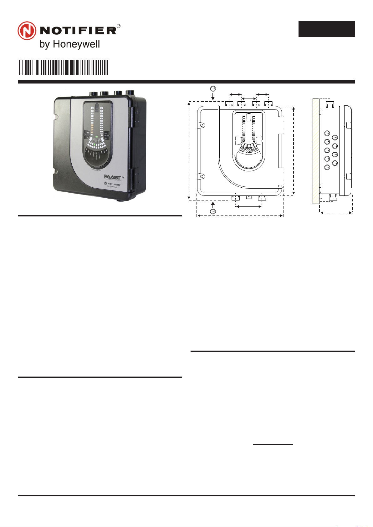
367 mm
135 mm
56 mm
44 mm
403 mm
356 mm
50 mm 50 mm
60 mm
110 mm
®
I 56- 3947- 2 02
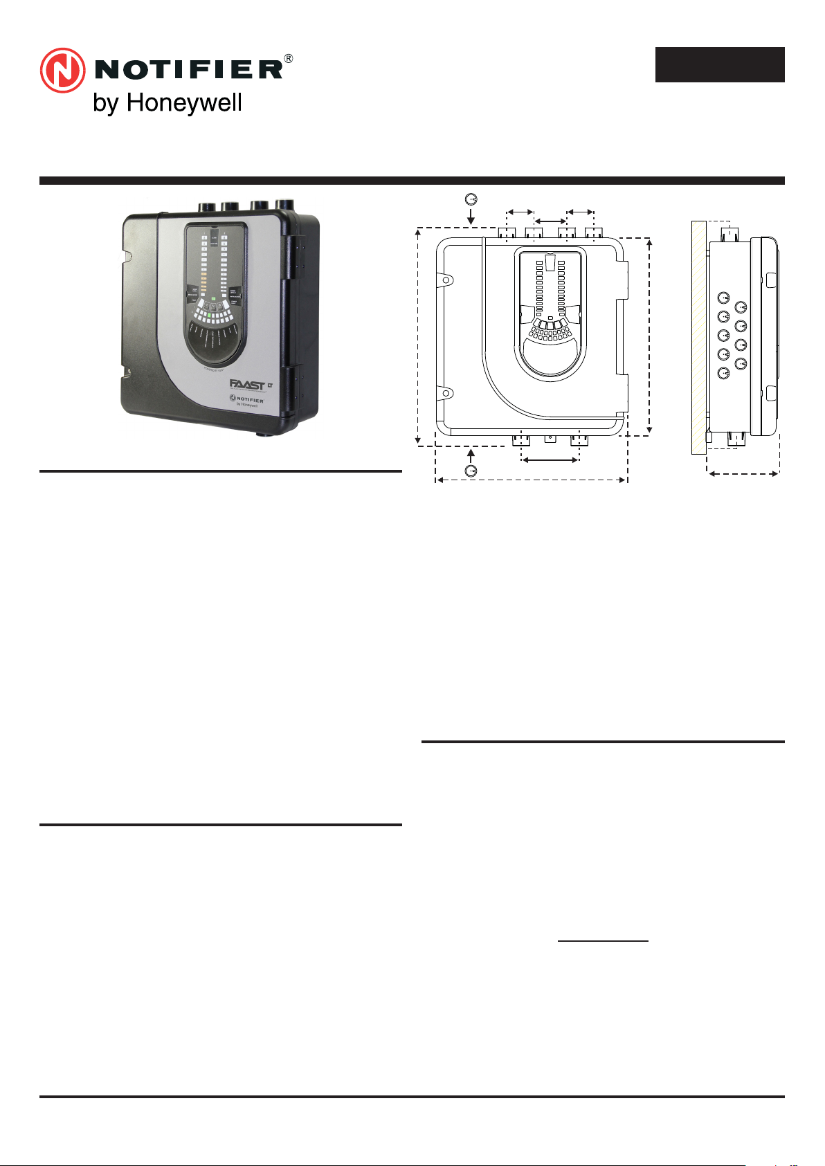
FIRE ALARM ASPIRATION SENSING TECHNOLOGY
QUICK INSTALLATION GUIDE ADDRESSABLE FAAST LT
MODELS NFXI-ASD11, NFXI-ASD12, NFXI-ASD22
DESCRIPTION
The LT NFXI-ASD Series is part of the Fire Alarm Aspiration
Sensing Technology® (FAAST) family. FAAST is an advanced
re detection system for use where early warning and very early
warning are a requirement. The system continuously draws air
from the controlled environment through a series of sampling holes
to monitor the environment for smoke particulate.
The NFXI-ASD is the addressable version of the FAAST LT range,
communicating with the CIE (Fire Panel) via a proprietary loop
protocol. It is available in 3 different models:
NFXI-ASD11 - Has single channel capability with one laser smoke
sensor.
NFXI-ASD12 - Has single channel capability with two laser smoke
sensors in a common chamber for coincidence
detection.
NFXI-ASD22 - Has two channel capability with two laser smoke
sensors in separate chambers. (one sensor for
each channel).
This guide provides information for mounting and basic installation
using the unit’s default factory settings. For more advanced information
please see the FAAST LT Advanced Setup and Control Guide.
SPECIFICATIONS
Electrical Characteristics
Voltage Range: 18.5 - 31.5 VDC
Supply Current: 1 Channel: 170mA (typical); 360mA (max) @
2 Channel: 270mA (typical); 570mA (max) @
Communication Loop Supply Voltage: 15 – 29 VDC (Loop current ≤
Communication Loop Standby Current: @ 24V: 900 µA max. (poll once
Module Isolator Characteristics
Maximum rated switching current
(under short circuit, Is max): 0.9A @ ≤ 29V
Maximum leakage current (IL max)
with the switch open (isolated state): 15mA
Maximum series impedance with
the switch closed (Zc max): 190 m ohm at 15Vdc; 1A
24 VDC 25oC (excluding sounders)
24 VDC 25oC (excluding sounders)
900mA)
every 5s)
Power Reset: 0.5s
Congurable Input: Activation Time: 2s (min)
Relay Contact Ratings: 2.0 A @ 30 VDC, 0.5A @ 30 VAC
Environmental Ratings
Temperature: -10°C to 55°C
Relative Humidity: 10% to 93% (non-condensing)
IP Rating: 65
Mechanical
Exterior Dimensions: See Figure 1
Wiring: 0.5 mm² to 2 mm² max
Maximum Single Pipe Length: 100m (Classes B & C) 80m (A)
Maximum Branched Pipe Length: 160m (2 x 80m, Class C)
Maximum Number of Holes See Table 1A
Pipe Spec (EN54-20 Compliance): to EN 61386
(Crush 1, Impact 1, Temp 31)
Outside Pipe Diameter: 25mm (nom) or 27mm (nom)
Shipping Weight: 6.5kg (inc sensors)
PARTS LIST
Description Quantity
FAAST LT unit 1
Mounting bracket 1
3-pin Terminal block 6
4-pin Terminal block 1
2-pin Terminal block 3
47 k-ohm EOL Resistor 2
USB Cable 1
Front Panel Labelling Pack 1
Wiring Diagram Label 1
Installation Kit CD 1
Quick Installation Guide 1
Aspirating Smoke Detectors supplied and installed within the
EU must conform to the EU Construction Products Regulation
(CPR) 305/2011 and the related European Product Standard EN
54-20. FAAST LT has been tested and certied to ensure that it
conforms to the necessary Standards, but strict adherence to this
instruction guide is advised to ensure that the installation meets
the requirements of the CPR.
N200-102-00 1 I56-3947-202
Figure 1: Dimensions and Knock-Outs
Important Note

Warning
1 2 3 4 5 6 7 8 9101112131415161718
90 mm
The performance of this system is dependent upon the pipe
network. Any extension or modication to the designed
installation may cause improper operation. The operational
effects of such changes need to be veried using the PipeIQ
2 design software.
This equipment and all associated pipe work must be installed in
accordance with all relevant codes and regulations.
PHYSICAL INSTALLATION
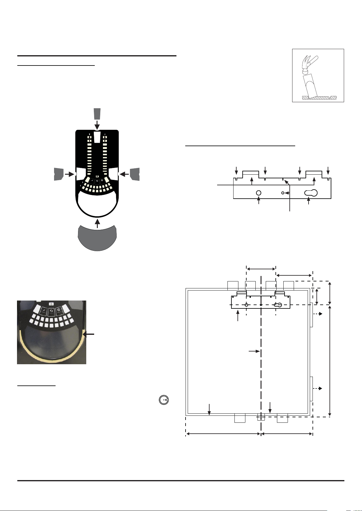
Front Panel Labels
The LT NFXI-ASD is shipped without the front panel labels
xed in place. This allows the installer to choose the language
required for the installation from the Front Panel Labelling Pack.
Figure 2 shows where the labels need to be placed:
Figure 4: How to Knock Out Cable
Gland Holes
Mounting the LT NFXI-ASD to the Wall
ALARM
PREALARM
10
10
9
9
8
8
7
7
6
6
5
5
4
4
3
3
2
MODULE1
SMOKE
LEVEL1
FAULT
2
1
1
SMOKE
LEVEL2
MODULE2
POWER
FAULT
A
HIGHFLOW
FILTER
SOUNDER
TEMPERATURE
ELBASID/MESY
INPUT
LOWFLOW
SENSOR
ASPIRATOR
T
S
Figure 2: Placing the Front Panel Labels
When label A is in place, remove the protector from the bottom of
the clear cover to stick the cover down, as shown in Figure 3:
FAAST LT
HANGING LUGS
POSITION OF BRACKET
INDICATES CENTRE OF ASPIRATING PIPES
FIXING HOLE FIXING HOLE
USE FOR PLUMB-LINE
Figure 5: Mounting Bracket
99 mm
41
mm
59
mm
*
PLUMB LINE
329
mm
Figure 3: Remove Backing to
Stick Cover Down
Cable Access
Knock out cable gland holes where required. The
location of the cable gland holes is shown in Figure 1,
represented by the icon:
OUTER DIMENSION OF UNIT
212 mm
BASE OUTLINE
144 mm
* Minimum clearance required from hinges to open door = 35 mm.
Figure 6: Fasten the mounting bracket to the wall
*
N200-102-00 2 I56-3947-202
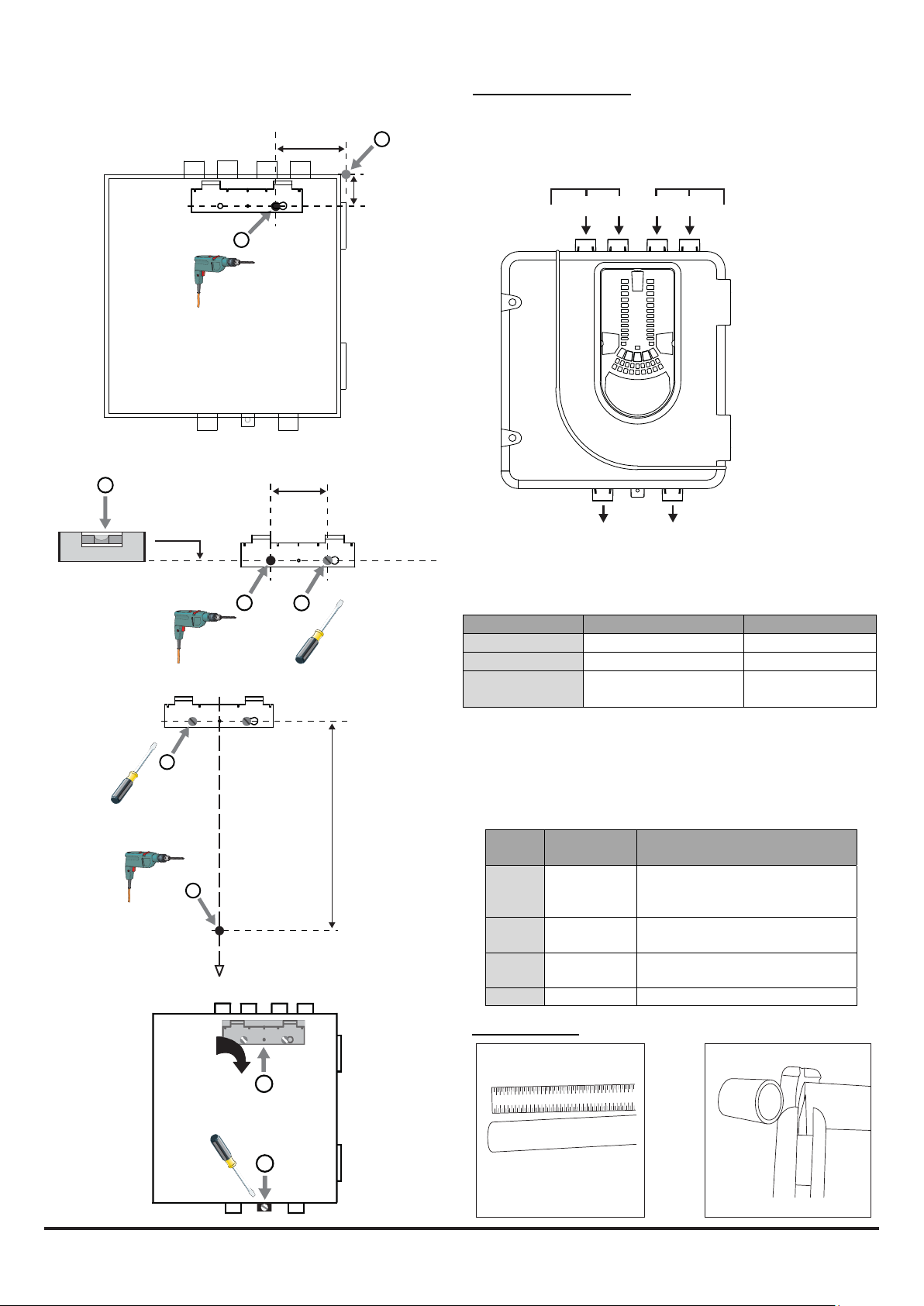
Figure 7: Sequence (1 to 9) to Mount the Detector on the Bracket
1 2 3 4 5 6 7 8 9 101112131415161718
7a
41
mm
1
99 mm
2
Pipe Hole Conguration
Figure 8 below shows the pipe holes available on the unit. Each
unit has 2 pipe holes per channel connected together like a T-Piece.
If using a 1 channel unit, holes 3 and 4 do not function. Use Table
1 to locate the holes required for the installation:
3
1
CHANNEL 1 CHANNEL 2 (ONLY FUNCTION
2
4
ON 2 CHANNEL UNITS)
Figure 8: Pipe Holes
7b
7c
7d
4
o
0.00
90 mm
CHANNEL 1 (NOT
USED FOR COMMON
CHAMBER UNIT)
5
3
Table 1: Pipe Holes Used for Each FAAST LT Model
5
CHANNEL 2 (ONLY FUNCTIONS
6
ON 2 CHANNEL AND COMMON
CHAMBER UNITS)
FAASTLTMODEL INLETPIPEHOLE OUTLETPIPEHOLE
NFXI‐ASD11 1and/or2 5
NFXI‐ASD12 1and/or2 6
NFXI‐ASD22 Channel1‐1and/or2
Channel2–3and/or456
Note 1: Pipe holes not used should be kept sealed.
Note 2: Do NOT glue pipes into the pipe holes.
6
Table 1a: Maximum Number of Pipe Holes Allowed Per Channel
for EN54-20 Compliance
329 mm
All gures quoted using highest (level 1) sensitivity.
CLASS PIPELENGTH
(m)
MAXNUMBEROFHOLESPER
CHANNEL
C 100 18(5x2mm,6x2.5mm,3x3mm,
7
3x3.5mmand1x4mm)+4mm
nonsensingendhole
C 160(2x80)
UsingT‐Piece
9holesperbranch(3x2.5mm,6x
3mm)+3mmnonsensingendhole
B 100 6(2x3.5mm,2x4mm,2x5mm
incendhole)
A 80 3(1x5mm,2x6mmincendhole)
Pipe Installation
8
1 2 3 4 5 6 7 8 9 10111213141516
1718
9
1 2
N200-102-00 3 I56-3947-202
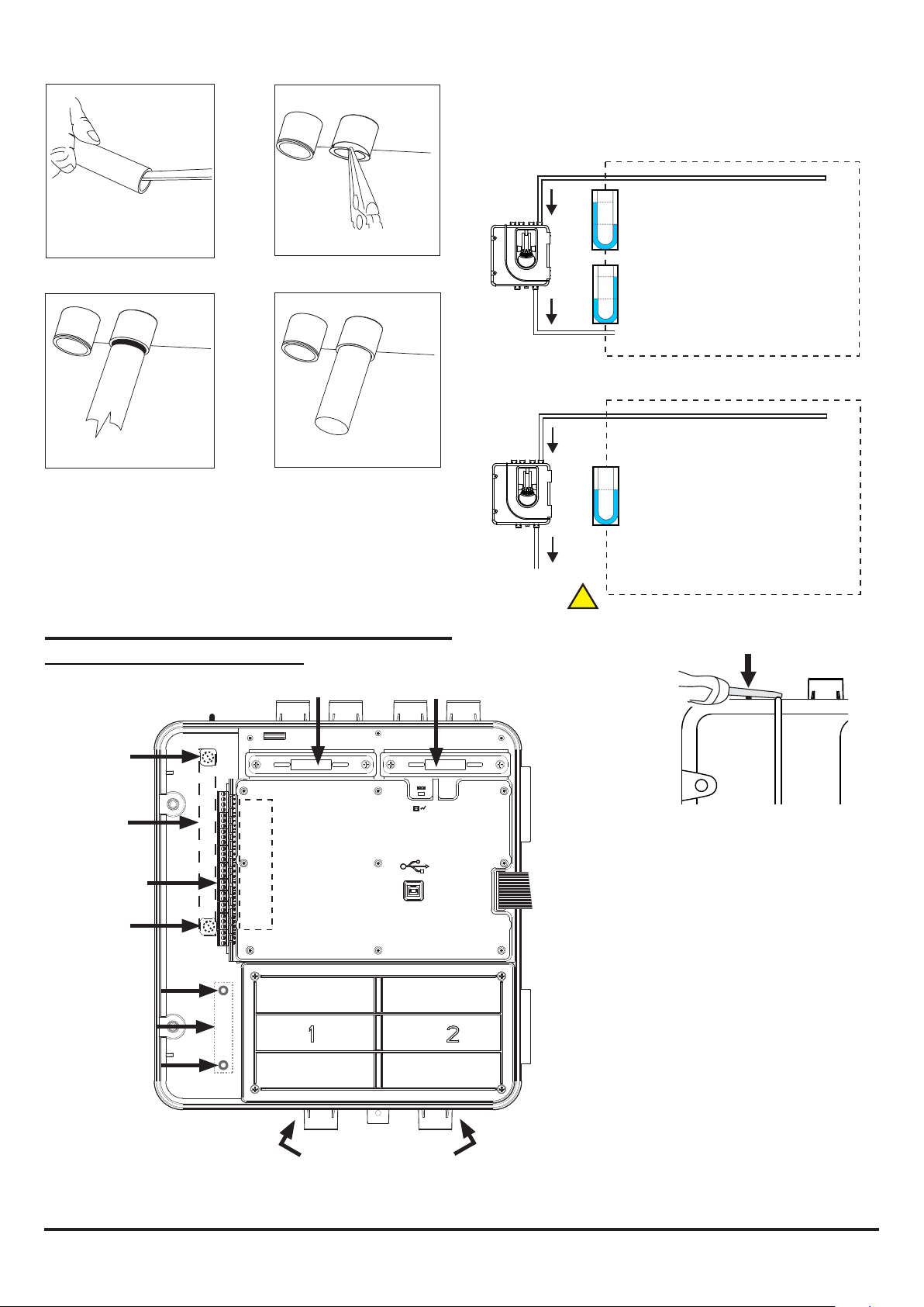
Exhaust Pipe
1 2 3 4 5 6 7 8 9 10111213141516 1718
1 2 3 4 5 6 7 8 9 1011121314 15161718
1 2 3 4 5 6 7 8 9 101112131415161718
1 2 3 4 5 6 7 8 9 10 1112 131415161718
Whenever the FAAST LT is installed outside the risk area, return of
the exhaust air back into the protected area can reduce ow faults
due to pressure difference.
3 4
5 6
WIRING INSTALLATION
Power, Alarm and Control Connections
CHANNEL 1 FILTER
CHANNEL 2 FILTER
SAMPLING AREA
SAMPLING AREA
!
EARTH BAR
MOUNT
F-LT-EB
EARTH BAR
(OPTIONAL)
POWER AND
ALARM
CONNECTIONS
EARTH BAR
MOUNT
MODULE MOUNT
F-LT-PMB
MODULE MOUNT
KIT (OPTIONAL)*
MODULE MOUNT
*If required, an input/output module
can be installed into the FAAST LT
unit. The optional module mount kit
(F-LT-PMB) will be needed for this.
PLACE
WIRING
LABEL
HERE
SENSOR COVER
POSITION FOR
TEST MAGNET
If the FAAST LT door is closed for a long time
(especially at high temperatures) it may be
necessary to use a at-bladed screwdriver
between the two tabs at the top of the unit to
lever open the door (as shown above).
USB PORT
Figure 9: Inside the Detector
Note 1: All wiring should comply with local
requirements and regulations.
Note 2: Loop wiring must observe the
recommendations of the panel manufacturer
N200-102-00 4 I56-3947-202

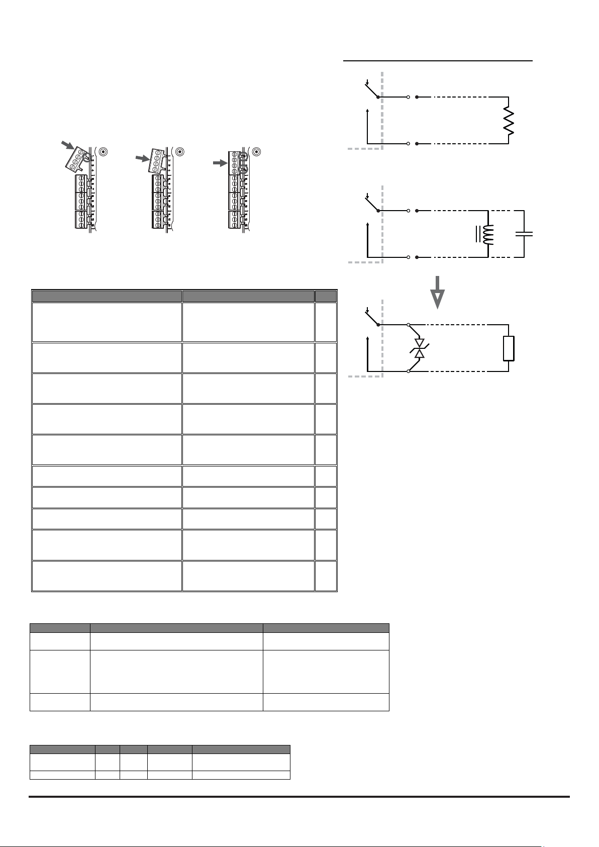
Fitting the Terminal Blocks
To insert the terminal blocks into the unit use the following method:
1 Insert a corner of the block into the slot (see a).
2 Push the length of the block into the slot until the block ‘clicks’
into place, the 2 upper hooks on the block should be visible
(see c).
a
b c
WARNING: Switching Inductive Loads
FAAST LT
FAAST LT
R
Table 2: Wiring Terminal Designations
(Note - Terminals marked CH2 will only be available on 2 channel
models)
No. Function
1 Ext Power In +
2 Ext Power In 3 Aux Power In +
4 Aux Power In -
5 NC Alarm Relay
6 C Alarm Relay
7 NO Alarm Relay
8 NC Alarm Relay
9 C Alarm Relay
10 NO Alarm Relay
11 NC Fault Relay
12 C Fault Relay
13 NO Fault Relay
14 NC Fault Relay (AUX)
15 C Fault Relay (AUX)
16 NO Fault Relay (AUX)
17 Sounder Output 1 18 Sounder Output 1 +
19 Sounder Output 2 20 Sounder Output 2 +
21 Configurable Input +
22 Configurable Input -
23 Not Used
24 Loop out 25 Loop switched out +
26 Loop in 27 Loop in +
28 Loop not switched out +
Primary PSU
Primary PSU
Not used in default
Not used in default
CH1
CH1
CH1
CH2
CH2
CH2
CH1
CH1
CH1
CH2
CH2
CH2
47 k-ohm EOL Resistor
47 k-ohm EOL Resistor
(Reset)
(Reset)
To use isolator
Internally connected to 27
Default is active = short circuit
(unsupervised)
T1
T2
T3
T4
T5
T6
T7
T8
T9
T10
FAAST LT
1N6284CA
Inductive loads can cause switching surges, which may
damage the module relay contacts (see above).
To protect the relay contacts, connect a suitable Transient
Voltage Suppressor (for example 1N6284CA ) across the
load as shown.
Alternatively, for unsupervised DC applications, t a diode
with a reverse breakdown voltage greater than 10 times the
circuit voltage.
L/C
CL
Table 3: Relays
RELAY ACTION: NOTES
ALARM 1 or 2 Controlled by panel when it determines
FAULT 1 or 2 When FAULT CONDITION on Ch1 or Ch2
SOUNDER 1 or 2 Set ON when a channel is in ALARM.
alarm condition has been met.
or a common FAULT occurs. Fault is also
signalled when in Service Mode and when
the device is unpowered.
Sounder 1 corresponds to Ch1 and
Sounder 2 corresponds to Ch2
Set ON and OFF by panel; not latched
Fault state is not latched.
Default condition = set on in ALARM.
Table 3a: Relay Electrical Specication
SPECIFICATION MIN MAX UNITS COMMENTS
Contact Rating 2
0.5
Life Time 105 Operations
A
A
30 VDC resistive load
30 VAC resistive load
N200-102-00 5 I56-3947-202

X 10 X 1
SETTING THE ADDRESSES POWERING UP
Each aspiration channel uses loop communications to report its
status information to the CIE (Fire Panel). As a factory default,
the unit will report smoke alarm and sensor information at an
associated sensor address and general alerts and faults on a
different module address.
Figure 10: Address Switches
Sensor
The sensor address is set on rotary decade switches on the back
of the smoke sensing devices. The smoke sensors are located
under the sensor cover inside the unit (see Figure 9). The Smoke
Sensors section of Service - later in the manual - shows how
to remove the sensors. As supplied, the default for channel 1 is
Address 1; in 2 channel units (or when two sensors are tted) the
second device is set to Address 2.
Any sensor address may be used except 0, whilst respecting the
panel’s rules on co-operative Multi-Sensing* (see below) between
the VIEW™ smoke sensors.
Note: The sensors communicate with the re panel through the
loop connection whether the 24VDC power supply is on or not.
Module
The module address is set by means of rotary decade address
switches located behind the door of the unit. Use a screwdriver to
rotate the wheels to the desired address. The selected address
refers to channel 1; on 2 channel units the device assigns the next
(+1) module address to channel 2 automatically. Hence, address
159 is not valid for channel 1. (Note: for control panels that use
only 99 addresses, 99 is invalid for channel 1.)
Note: The module address will only respond to a panel poll when
in Normal mode with the 24VDC power supply on.
* Co-Operative Multi-Sensing
Depending upon the panel used, the rules to dene the co-operative
Multi-Sensing between the VIEW™ smoke sensors differs. This
mode will allow an even higher sensitivity, but is only to be used for
the sensors within a single NFXI-ASD12.
How to Set this up for the NF300, NF3000, NF500, NF5000 and
ID3000 Panels
The co-operative Multi-Sensing is automatically activated if the
VIEW™ sensors on a loop are set to adjacent sensor addresses
and if they are also put into the same zone. Additionally, if cells
are being used, the cell numbers for the co-operative sensors must
also be the same.
How to Set this up for the NF50-A, NF50, NF50-S, ID60 and
Pearl Panels
The co-operative Multi-Sensing is automatically activated if the
VIEW™ sensors on a loop are put into the same AWACS group.
Setting an AWACS group to 0 will disable co-operative Multi-
Sensing for that sensor.
Using Default Settings
1. Connect a suitable 24VDC supply (complying with European
Standard EN 54-4) to pins 1 and 2 on terminal block T1 (See
Table 2)
2. Check the voltage at the connector. Make sure it is within the
required voltage range.
3. If the voltage is within the specied range, connect the power
connector to the unit.
4. Close and secure the housing door; verify the fan starts up and
air ows out of the exhaust port. The unit takes 1-3 minutes to
initialise and stabilise in normal mode.
EXTERNAL RESET
The default setting for the congurable external input is Device
Reset (terminal block T8). A short circuit connection between these
terminals will cause the FAAST LT unit to perform a reset.
N200-102-00 6 I56-3947-202
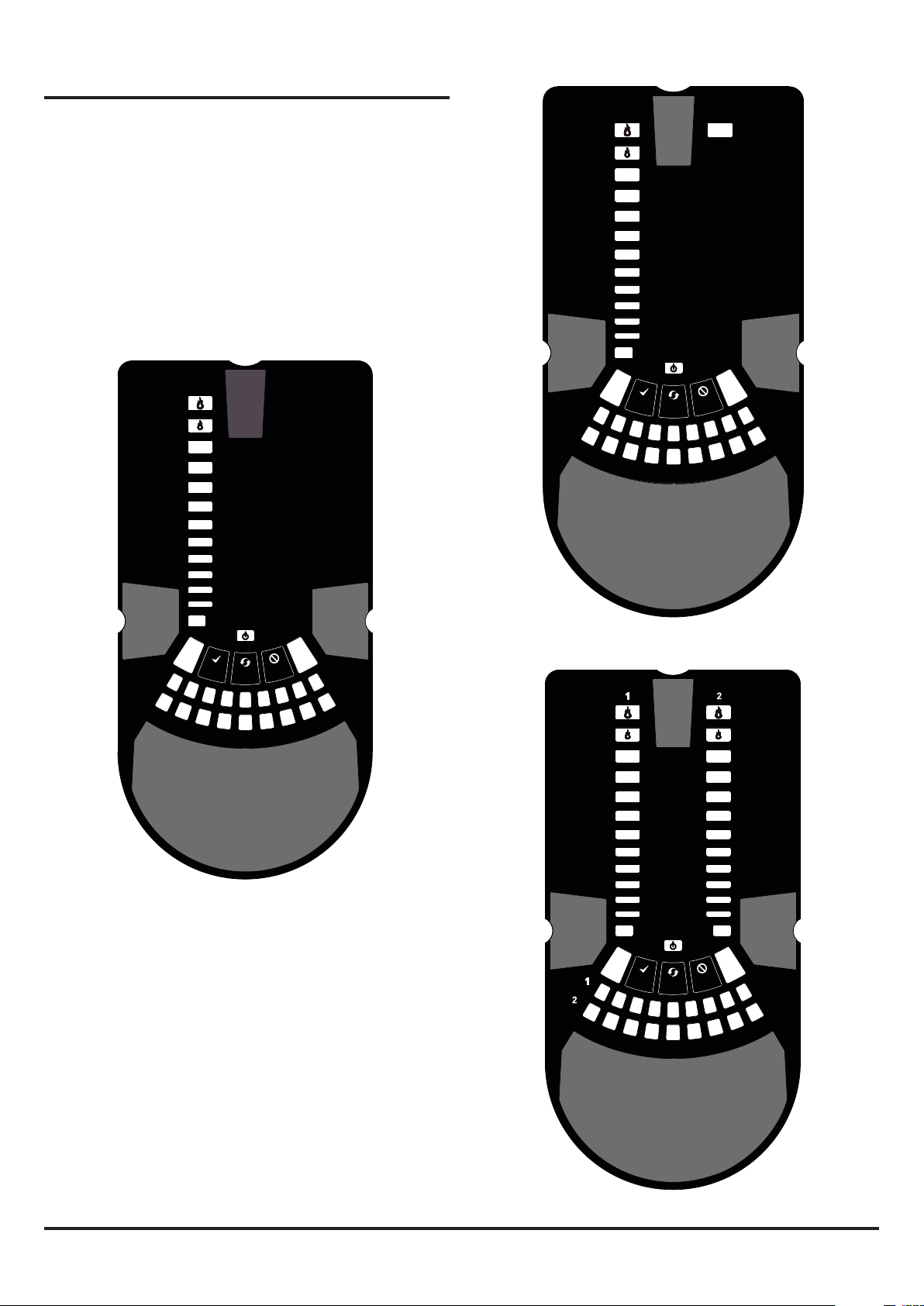
FRONT PANEL
The front panel will be different depending on which of the 3 NFXIASD models is being installed, and each is shown below.
The following information is displayed:
• Detector Status: Normal, Alarm, Fault or Isolate
• Alarm Level; Alarm, Pre-Alarm - only available with panels
using Advanced Protocol
• Particulate Levels; 1-9 - only available with panels using
Advanced Protocol
• Flow Level
• Test, Reset and Disable Buttons
Figure 11: Front Panel Display
ALARM
PREALARM
10
9
8
7
6
5
4
3
LEVEL
2
1
POWER
FAULT
SMOKE
MODULE
FAULT
ALARM
PREALARM
10
9
8
7
6
5
4
3
INPUT
2
1
SENSOR
ASPIRATOR
POWER
FAULT
HIGH FLOW
FILTER
SOUNDER
TEMPERATURE
ELBASID/METSYS
SMOKE
LEVEL
MODULE
FAULT
LOW FLOW
11b: NFXI-ASD12 1 Channel Detector (2 Sensors)
HIGH FLOW
FILTER
SOUNDER
TEMPERATURE
LOW FLOW
INPUT
SENSOR
ELBASID/METSYS
ASPIRATOR
11a: NFXI-ASD11 1 Channel Detector (1 Sensor)
SMOKE
LEVEL 1
MODULE 1
FAULT
LOW FLOW
INPUT
10
9
8
7
6
5
4
3
2
1
SENSOR
ASPIRATOR
ALARM
PREALARM
ELBASID/MESY
T
S
TEMPERATURE
10
9
8
7
6
5
4
3
2
1
SOUNDER
SMOKE
LEVEL 2
MODULE 2
POWER
FAULT
FILTER
HIGH FLOW
11c: NFXI-ASD22 2 Channel Detector
N200-102-00 7 I56-3947-202
Table 4: Front Panel Indicators and Fault Descriptions
FAULT
POWER
LEVEL 2
SMOKE
INITIALIZATION
ALARM
PREALARM
2
10
3
1
4
5
6
7
8
9
2
10
3
1
4
5
6
7
8
9
INDICATOR ACTION WARNING OR TROUBLE COMMENT / ACTION
CHANNEL 1/2 ALARM ON Red
CHANNEL 1/2 PRE-
ALARM
SMOKE LEVEL 1/2 ON Yellow
CHANNEL 1/2 MODULE ON Green Controlled by panel
FAULT ON Yellow Common or multiple faults
POWER ON Green FAAST LT is powered Displays Yellow when initialising
POWER FAULT ON Yellow Low power alert / high power
CHANNEL FLOW
INDICATORS 1/2
LOW FLOW ON Yellow Low flow fault Check filter; check pipe network for blockages.
INPUT 1 BLINK Yellow External input fault Not used with default settings
SENSOR 2 BLINKS Yellow Sensor communication fault Check sensor addresses and installation;
ASPIRATOR ON Yellow Air flow sensor fault Try to restart device.
DISABLE 1 BLINK Yellow Alarms & alerts not reported Returns to Maintenance then Normal operation
SYSTEM 1 BLINK Yellow Wrong configuration Flashes all FAULT LEDs; try to restart device.
TEMPERATURE 1 BLINK Yellow Low temperature alert Check the air flow temperature
SOUNDER 1 BLINK Yellow Sounder fault Check the sounder circuit and the EOL
FILTER 1 BLINK Yellow Filter alert at set date No date set as default
HIGH FLOW ON Yellow High flow fault Check pipe network for breaks or leaks.
In case of simultaneous alerts/faults on the same LED, priority order is: ON (Highest), 1 blink, 2 blinks, 3 blinks (Lowest)
Note: The channel alarm and smoke level LEDs are under the
(Set by panel)
1 BLINK Green
(Polled by panel)
ON Yellow Channel is in pre-alarm Only with panels using Advanced Protocol
(Set by panel)
BLINK Green Module communication Controlled by panel
ON Green The LED indicates the air flow
1 BLINK Yellow Flow initialization fault Check filter; check pipe network for blockages;
2 BLINKS Yellow Fan fault Try to restart device.
2 BLINKS Yellow EEPROM fault Check power supply voltage. Try to restart
3 BLINKS Yellow Real time clock fault RTC is corrupted or time reading failed.
2 BLINKS Yellow High temperature alert Check the air flow temperature
Channel is in alarm (relay is
set ON with no delay)
When sensor is polled Not when in alarm
Led number indicates sensor
alarm level reached
fault
for a channel:
- Centre = normal flow
- Left = flow low;
(-20% at extreme)
- Right = flow high;
(+20% at extreme)
Default setting
Only numbers 1 – 9 used - only with panels
using Advanced Protocol
Check the power supply voltage.
On 2 channel unit:
Upper row = Ch1
Lower row = Ch2
replace sensor.
try to restart device.
after 60min (default)
device
control of the CIE (Fire Panel).
Front Panel Buttons
The front panel has 3 user buttons: TEST, RESET and DISABLE.
These buttons are used to enter the pass-code which then allows
the user to carry out simple test functions.
Note: In Remote Maintenance and Service Mode, these buttons
are always disabled.
Figure 12: User Interface Buttons
N200-102-00 8 I56-3947-202
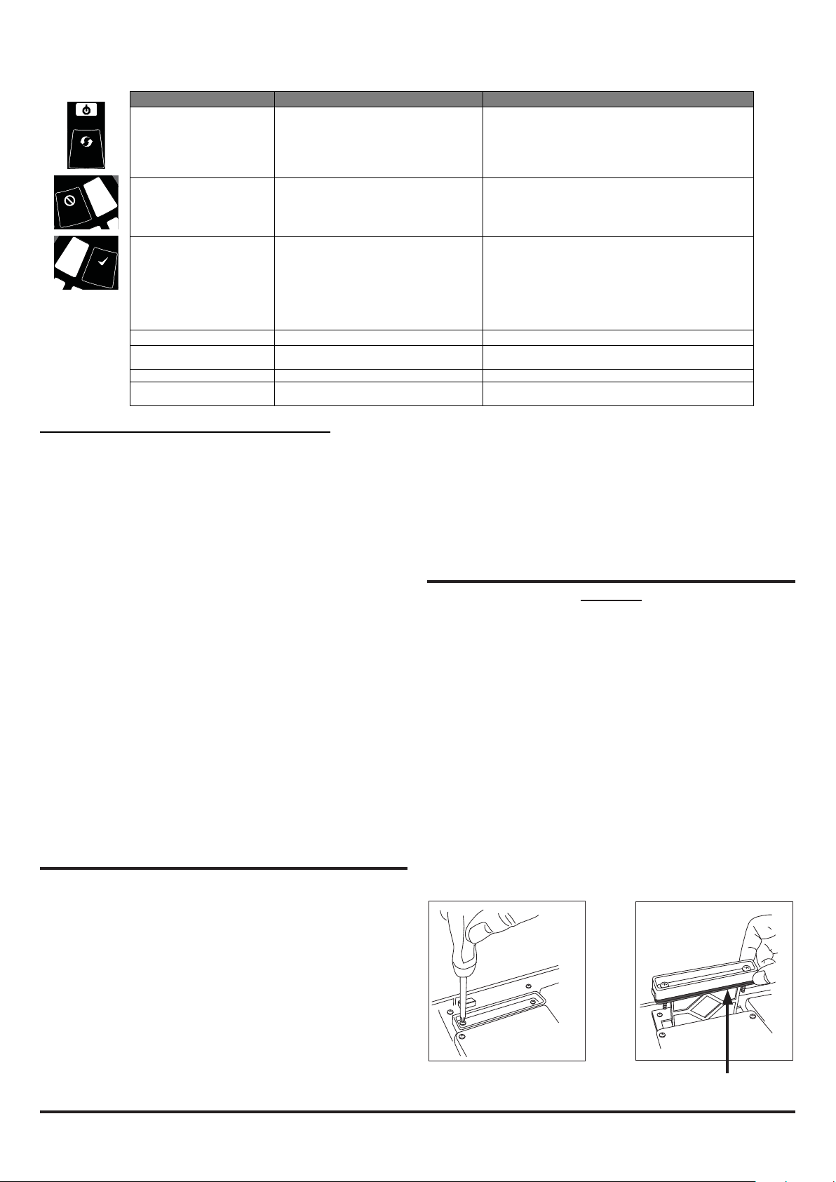
Table 5: Front Panel Buttons
FAULT
POWER
LEVEL 2
SMOKE
INITIALIZATION
ALARM
PREALARM
2
10
3
1
4
5
6
7
8
9
FAULT
POWER
LEVEL 2
SMOKE
INITIALIZATION
2
10
3
1
4
5
6
7
8
9
FAULT
POWER
LEVEL 2
SMOKE
INITIALIZATION
ALARM
PREALARM
2
10
3
1
4
5
6
7
8
9
2
10
3
1
4
5
6
7
8
9
BUTTON NORMAL Mode MAINTENANCE Mode
RESET When pressed for 2 s, starts PASSWORD
PROCEDURE to enter Maintenance
mode.
DISABLE Used to increment Password digits in
PASSWORD PROCEDURE
TEST Used to confirm password in PASSWORD
PROCEDURE. Default Password = 3111
When pressed for 2 s latched alarms, faults and
sounders (relays) are reset. Alarm controlled by panel. If
alarm persists, set again immediately after the reset
In DISABLE Mode, if pressed for 2 s unit will exit from
DISABLE Mode (but remains in MAINTENANCE Mode)
When pressed for 2 s, device enters DISABLE Mode for
60 minutes (default). Alarm and fault relays reset .
Smoke sensors continue to report alarm and their faults
to the panel.
(To exit DISABLE Mode see RESET)
When pressed for 2 s and released, both sensor will
simulate alarm
When pressed for 4 s and released, sensor #1 will
simulate alarm
When pressed for 6 s and released, sensor #2 will
simulate alarm
Warning: Outputs will be activated by test
COMBINATIONS
RESET + DISABLE When pressed for 2 s, shows fan speed
(on smoke level scales) for a preset time.
RESET + TEST No action When pressed for 2 s, turns off sounders
RESET + TEST + DISABLE No action When pressed for 2 s, unit exits from MAINTENANCE
When pressed for 2 s, shows fan speed (on smoke level
scales) for preset time.
Mode
Password Sequence to Enter Maintenance Mode
Press and hold RESET; Left ow indicator will turn yellow, then
green.
Release RESET and FAULT indicator will switch on green. The
left ow indicator will blink green indicating the device is ready for
the rst digit.
Press DISABLE to increment the LEDs 1…9; press TEST to select
a digit.
The ashing airow segment will turn solid green and the next
segment will begin to ash indicating set the next digit. When the
4th digit is selected, all 4 airow segments are turned off. If the
password is accepted the FAULT indicator will remain green and
the unit enters Maintenance mode. If the password is incorrect
the FAULT indicator ashes yellow and the unit remains in Normal
mode. The Default password in 3111.
If no button is pressed for 10s during the password sequence, the
unit returns to Normal mode.
Exit from Maintenance Mode
To exit from the Maintenance mode, press the three front panel
user interface buttons TEST, RESET and DISABLE simultaneously
for 2 seconds. Alternatively, reset the unit using the Remote Input
(when set to default value) or power the device off and on again.
If there is no activity in Maintenance mode for 5 minutes (default),
the FAULT indicator blinks green for 15s and then the unit
automatically returns to the Normal state.
TESTING
Note that the sensor LEDs, which are under the control of the CIE
(Fire Panel), must be turned on to activate the front panel alarm
indicators.
Magnet Test
The alarm signalling can be tested for functionality by placing a
test magnet in the position shown in Figure 9 (displayed earlier in
the guide). This method does not test the air ow in the pipe-work.
Smoke Testing
The system alarm response can be tested for functionality
using smoke. The choice of smoke source is dependant on the
installation but in all cases the smoke must be present for the
duration of the test. Smoke pellets or matches can be used close
to the sampling point to introduce smoke particulates into the
N200-102-00 9 I56-3947-202
system. It is recommended that smoke with a particulate life cycle
of greater than 120s should be used – standard aerosol sprays for
point detector testing do not work well on aspirated systems.
Fault Testing
Simulate a fault on the detector (for example, block the outlet pipe)
and check that a fault is signalled on both the front panel of the unit
and at the CIE (Fire Panel).
SERVICE
WARNING
Isolate the aspirating detector from the re alarm system to prevent
any unwanted alarms when opening the front door of the unit.
Make sure all power is removed from the system before removing
any covers.
Service Mode
Opening the cabinet door during normal operation will cause the
unit to enter Service Mode. The FILTER LEDs will blink, the unit will
switch off power to the fans and stops communicating with the re
panel (the smoke sensors continue to communicate with the panel).
When the cabinet door is closed, the unit restarts automatically.
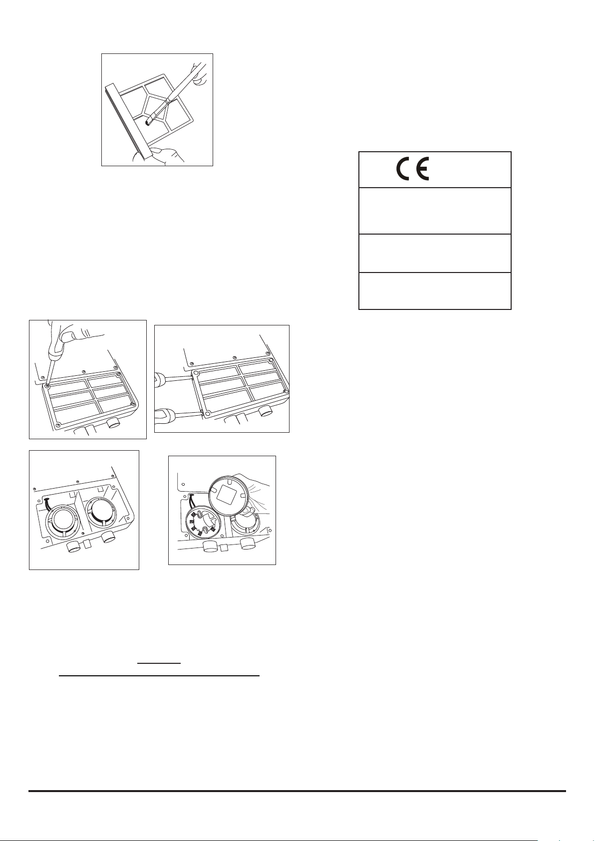
Filters
Periodic cleaning or replacement of the lters will be required.
The lters are located inside the cabinet at the top of the unit (see
Figure 9 displayed earlier in the guide) and are removed as shown
in the sequence below:
1 2
FOAM GASKET
3
Either replace the lter assembly or carefully brush off the
accumulated dust.
Note: If replacing the lter, remove the foam gasket from the old
lter and place onto the new lter. When placing the new lter into
the slot, ensure that the gasket is correctly aligned.
Ret the lter, close and secure the cabinet door. The unit will
initialise and restart.
Smoke Sensors
The smoke sensors are located under the sensor cover (see Figure
8 displayed earlier in the guide). To access the sensors, follow the
sequence below:
2
Conguring Other Options
To change any of the default options, it will be necessary to connect
the detector to a PC/laptop with the PipeIQ 2 software installed;
see the FAAST LT Advanced Setup and Control Guide for further
information.
Note: The USB connecting cable should be removed during
normal operation.
0832 12
Declaration of Performance Ref:
NFXI-ASD11: DOP-ASP012
NFXI-ASD12: DOP-ASP013
NFXI-ASD22: DOP-ASP014
EN54-20 : 2006 Class C
Aspirating Smoke Detectors
EN54-17: 2005 Short Circuit Isolators
System Sensor Europe
Pittway Tecnologica S.r.l.
Via Caboto 19/3, 34147 Trieste, Italy
1
4
3
If replacing a sensor, ensure that the address set on the new
sensor is the same as on the sensor being replaced.
LASER SAFETY INFORMATION
The detector contains a Class 1 laser product. Radiation emitted
inside the smoke sensor is completely contained within its housings
and protective covers during all phases of operation.
WARNING
Using compressed air to clean the pipe system
High pressure air ushed through the system could damage
the fan, ensure that the FAAST LT unit is sealed or detached
from the system before commencing this procedure.
USB CONNECTION
PC connectivity is provided by an on board USB B socket located
centrally between the lter and the sensor cover (see Figure 9
displayed earlier in the guide). The USB interface allows access to
a range of additional options via the PipeIQ 2 application software
running on a PC.
Notier by Honeywell
Brooks Road
Lewes
East Sussex
BN7 2BY
United Kingdom
www.notierresystems.co.uk
N200-102-00 10 I56-3947-202
I T A L I A N O
367 mm
135 mm
56 mm
44 mm
403 mm
356 mm
50 mm 50 mm
60 mm
110 mm
GUIDA DI INSTALLAZIONE RAPIDA FAAST LT INDIRIZZABILE
DESCRIZIONE
La serie LT NFXI-ASD fa parte della famiglia FAAST (Fire Alarm
Aspiration Sensing Technology®). FAAST è un sistema di rilevamento
di incendi avanzato da utilizzare dove sono richieste rilevazioni
di tipo “early warning” e “very early warning”. Il sistema aspira
continuamente l'aria dall'ambiente controllato attraverso una serie di
fori di campionamento per monitorare se nell'ambiente sono presenti
particelle di fumo.
Il modello NFXI-ASD è la versione indirizzabile della gamma FAAST LT,
che comunica con il CIE (pannello antincendio) tramite un protocollo
proprietario. È disponibile in 3 diversi modelli:
NFXI-ASD11 - Ha un singolo canale a disposizione con un rivelatore
laser di fumo.
NFXI-ASD12 - Ha un singolo canale a disposizione con due rivelatori
laser di fumo in una camera comune per il rilevamento
combinato.
NFXI-ASD22 - Ha due canali a disposizione con due rivelatori laser di
fumo in camere separate. (Un sensore per ogni canale.)
Questa guida fornisce informazioni per il montaggio e l'installazione di
base utilizzando le impostazioni di fabbrica predenite dell'unità. Per
informazioni più dettagliate consultare FAAST LT Advanced Setup and
Control Guide - riferimento D200-100-00.
SPECIFICHE
Caratteristiche elettriche
Intervallo di tensione: 18,5 - 31,5 VDC
Corrente di alimentazione: 1 Canale: 170 mA (tipico); 360 mA (max) a 24
2 Canali: 270 mA (tipico); 570 mA (max) a 24
Tensione di alimentazione del loop 15 - 29 VDC (corrente dei loop ≤ di
comunicazione: 900 mA)
Corrente a riposo del loop di comunicazione: A 24 V: 900 μA max. (un polling
Caratteristiche dell'isolatore del modulo
Corrente nominale massima di commutazione
(in condizioni di corto circuito, Is max): 0,9 A a ≤ 29 V
Corrente di dispersione massima (IL max)
con il selettore aperto (stato isolato): 15 mA
Massima impedenza in serie con
il selettore chiuso (Zc max): 190 m ohm a 15 Vcc; 1 A
Reset dell'alimentazione: 0,5 secondi
Input congurabile: Tempo di attivazione: 2 secondi (min)
Dati dei contatti relè: 2,0 A a 30 VDC, 0,5 A a 30 VAC
VDC 25 oC (escluse le sirene)
VDC 25 oC (escluse le sirene)
ogni 5 secondi)
FIRE ALARM ASPIRATION SENSING TECHNOLOGY
MODELLI NFXI-ASD11, NFXI-ASD12 E NFXI-ASD22
Figura 1: dimensioni e prefori
Dati ambientali
Temperatura: da -10 oC a 55 oC
Umidità relativa: dal 10% al 93% (senza condensa)
Classicazione IP: 65
Meccanica
Dimensioni esterne: Vedere Figura 1
Cablaggio: da 0,5 mm² a 2 mm² max
Lunghezza massima tubo singolo: 100 m (Classi B e C) 80 m (Classe A)
Lunghezza massima tubo collegato: 160 m (2 x 80 m, Classe C)
Numero massimo di fori: Vedere tabella 1A
Speciche tubi (conformità a EN54-20): secondo EN 61386
(urto 1, impatto 1, temperatura 31)
Diametro esterno tubo: 25 mm (nom.) o 27 mm (nom.)
Peso di spedizione: 6,5 kg (sensori inclusi)
ELENCO DELLE PARTI
Descrizione Quantità
Unità FAAST LT 1
Staffa di montaggio 1
Morsettiera a 3 posizioni 6
Morsettiera a 4 posizioni 1
Morsettiera a 2 posizioni 3
Resistenza di ne linea 47 KOhm 2
Cavo USB 1
Confezione di etichette per pannello anteriore 1
Etichetta schema di cablaggio 1
CD con kit di installazione 1
Guida di installazione rapida 1
Nota importante
I rivelatori di fumo ad aspirazione forniti e installati all'interno dell'UE
devono essere conformi alla direttiva dell'UE sui prodotti da costruzione
(CPR) 305/2011 e alla norma europea sui prodotti EN 54-20 correlata.
FAAST LT è stato sottoposto a veriche e certicazione per garantirne
la conformità agli standard necessari, ma si consiglia di attenersi
scrupolosamente a questa guida di istruzioni afnché l'installazione
soddis i requisiti CPR.
®
N200-102-00 1 I56-3947-202
Questa apparecchiatura e tutte le tubazioni associate devono essere
1 2 3 4 5 6 7 8 9101112131415161718
90 mm
installate in conformità a tutti i codici e alle normative pertinenti.
INSTALLAZIONE FISICA
Etichette per pannello anteriore
Il modello LT NFXI-ASD viene spedito senza etichette applicate sul
pannello anteriore. Ciò consente all'installatore di scegliere la lingua
richiesta per l'installazione dalla confezione di etichette per pannello
anteriore.
In Figura 2 viene mostrato dove devono essere applicate le etichette:
ALARM
PREALARM
10
10
9
9
8
8
7
7
6
6
5
5
4
4
3
3
2
MODULE1
SMOKE
LEVEL1
FAULT
2
1
1
SMOKE
LEVEL2
MODULE2
POWER
FAULT
Figura 4: come praticare i fori serracavo
Montaggio dell'unità LT NFXI-ASD alla parete
INDICA IL CENTRO DEI TUBI DI ASPIRAZIONE
FAAST LT
ALETTE
DI SUPPORTO
A
HIGHFLOW
FILTER
SOUNDER
TEMPERATURE
ELBASID/MESY
INPUT
LOWFLOW
SENSOR
ASPIRATOR
T
S
Figura 2: posizionamento delle etichette per pannello anteriore
Quando l'etichetta A è in posizione, rimuovere la protezione dalla
parte inferiore della copertura trasparente per incollare la copertura,
come mostrato in Figura 3:
Figura 3: Rimozione del
rivestimento per
incollare la copertura
FORO DI FISSAGGIO FORO DI FISSAGGIO
Figura 5: staffa di montaggio
POSIZIONE DELLA STAFFA
FILO A PIOMBO
USO DI FILO A PIOMBO
99 mm
41
mm
59
mm
*
329
mm
Accesso ai cavi
Praticare i fori serracavo dove necessario. La posizione
dei fori serracavo è mostrata in Figura 1, rappresentata
DIMENSIONE ESTERNA
DELL'UNITÀ
CONTORNO BASE
*
dall'icona:
212 mm
144 mm
* Spazio minimo necessario dai cardini per aprire lo sportello = 35 mm.
Figura 6: ssaggio della staffa di montaggio alla parete
N200-102-00 2 I56-3947-202
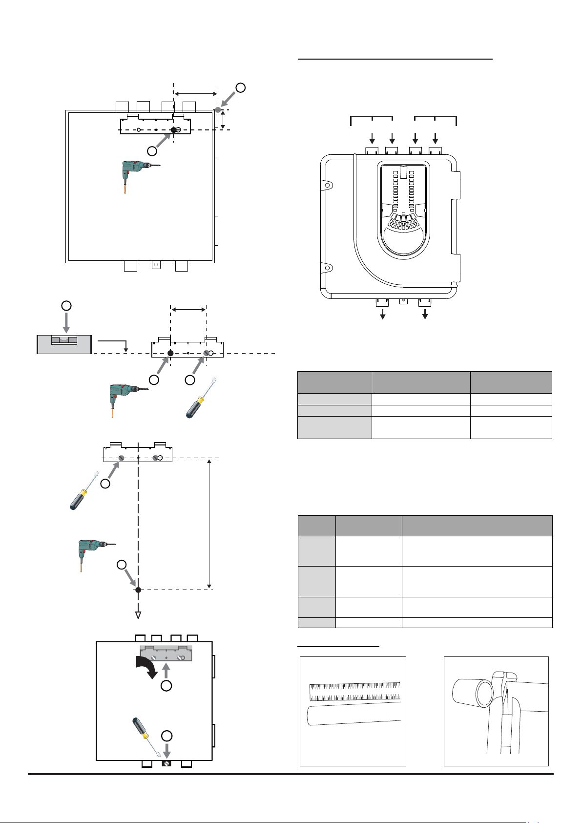
Figura 7: sequenza (da 1 a 9) per il montaggio del rivelatore
1 2 3 4 5 6 7 8 9 10111213 14 1516 1718
FAAST LT
ASPIRAZIONE
SCARICO
alla staffa
7a
41
mm
1
99 mm
2
Congurazione dei fori di entrata e uscita dei tubi
Figura 8 di seguito sono mostrati i fori di entrata e uscita dei tubi
disponibili sull'unità. Ogni unità dispone di 2 fori per tubi per canale
collegati insieme a T. Se si utilizza un'unità a 1 canale, i fori 3 e 4 non
funzionano. Utilizzare la Tabella 1 per localizzare i fori necessari per
l'installazione:
3
CANALE 1
1
2
4
CANALE 2 (FUNZIONA SOLO
SU UNITÀ A 2 CANALI)
Figura 8: fori di
entrata e uscita dei
7b
7c
7d
4
o
0.00
90 mm
CANALE 1 (NON
UTILIZZATO PER
L'UNITÀ A CAMERA
COMUNE)
CANALE 2 (FUNZIONA SOLO SU
5
UNITÀ A 2 CANALI E CAMERA
6
COMUNE)
Tabella 1: fori sui tubi utilizzati per ogni modello FAAST LT
5
3
MODELLO
FORO SU TUBO DI
FORO SU TUBO DI
NFXI-ASD11 1 e/o 2 5
NFXI-ASD12 1 e/o 2 6
6
7
329 mm
NFXI-ASD22 Canale 1 - 1 e/o 2
Canale 2 – 3 e/o 4
Nota 1: i fori sui tubi non utilizzati devono essere tenuti sigillati.
Nota 2: NON incollare i tubi nei relativi fori.
Tabella 1a: Numero massimo di fori per tubi consentito per canale
Tutte le cifre sono stimate usando il livello più elevato di sensibilità
(livello 1)
CLASSE LUNGHEZZADEL
TUBO(m)
C 100 18(5x2mm,6x2,5mm,3x3mm,3x
C 160(2x80)
Utilizzodel
raccordoaT
B 100 6(2x3,5mm,2x4mm,2x5mmincluso
A 80 3(1x5mm,2x6 mminclusoforofinale)
Installazione dei tubi
NUMEROMASSIMODIFORIPERCANALE
3,5mme1x4mm)+4mmforofinale
nonsensibile
9foriperraccordo(3x2,5mm,6x3mm)
+3mmforofinalenonsensibile
forofinale)
5
6
8
1 2 3 4 5 6 7 8 9 10111213141516
1718
9
1 2
N200-102-00 3 I56-3947-202
Tubo di scarico
1 2 3 4 5 6 7 8 9 10111213 14 1516 1718
1 2 3 4 5 6 7 8 9 10111213 1415161718
1 2 3 4 5 6 7 8 9 10111213 141516 1718
1 2 3 4 5 6 7 8 9 10 11 12131415161718
Ogni volta che FAAST LT viene installato al di fuori della zona a rischio,
il ritorno dell'aria di scarico nella zona protetta può ridurre i guasti di
usso dovuti alla differenza di pressione.
3 4
5
6
INSTALLAZIONE DEL CABLAGGIO
Collegamenti di alimentazione, allarme e controllo
FILTRO CANALE 1
FILTRO CANALE 2
AREA DI CAMPIONAMENTO
AREA DI CAMPIONAMENTO
!
MONTAGGIO
DELLA BARRA DI
TERRA
BARRA DI
TERRA F-LT-EB
(OPZIONALE)
COLLEGAMENTI
DI
ALIMENTAZIONE
E ALLARME
MONTAGGIO
DELLA BARRA
DI TERRA
MONTAGGIO
MODULO
KIT MONTAGGIO
MODULO F-LT-PMB
(OPZIONALE)*
MONTAGGIO
MODULO
*Se necessario, è possibile installare
un modulo di ingresso/uscita nell’unità
FAAST LT. Sarà necessario il kit opzionale
di montaggio modulo (F-LT-PMB).
POSIZIONARE
L'ETICHETTA DI
CABLAGGIO QUI
PORTA USB
COPERCHIO DEI SENSORI
POSIZIONE DEL
MAGNETE DI PROVA
Se la porta FAAST LT viene chiusa per un
lungo periodo (soprattutto ad alte temperature),
può essere necessario utilizzare un cacciavite
a lama piatta tra le due linguette nella parte
superiore dell'unità per mantenere aperta la
porta (come mostrato sopra).
Figura 9: interno del rivelatore
Nota 1: L'intero cablaggio deve rispettare i
requisiti e le norme locali.
Nota 2: Il cablaggio del circuito deve rispettare
le raccomandazioni del fabbricante del pannello
N200-102-00 4 I56-3947-202
N.
Funzione
1
Ingresso alimentazione est. +
PSU principale
T1
2
Ingresso alimentazione est. -
PSU principale
3
Ingresso alimentazione aus. +
Non in uso in impostazione predefinita
4
Ingresso alimentazione aus. -
Non in uso in impostazione predefinita
5
Relè di allarme NC
CH1
T2
6
Relè di allarme C
CH1
7
Relè di allarme NO
CH1
8
Relè di allarme NC
CH2
T3
9
Relè di allarme C
CH2
10
Relè di allarme NO
CH2
11
Relè di guasto NC
CH1
T4
12
Relè di guasto C
CH1
13
Relè di guasto NO
CH1
14
Relè di guasto NC (AUS.)
CH2
T5
15
Relè di guasto C (AUS.)
CH2
16
Relè di guasto NO (AUS.)
CH2
17
Uscita sirena 1 -
Resistenza di fine linea 47 KOhm
T6
18
Uscita sirena 1 +
19
Uscita sirena 2 -
Resistenza di fine linea 47 KOhm
T7
20
Uscita sirena 2 +
21
Input configurabile +
(Reset)
Valore predefinito attivo = corto circuito
(senza supervisione)
T8
22
Input configurabile -
(Reset)
23
Non in uso
T9
24
Uscita loop -
25
Uscita loop + 'isolatori'
Utilizzo isolatore
26
Ingresso loop -
T10
27
Ingresso loop +
28
Uscita loop + (no isolatori)
Collegato internamente al terminale 27
RELÈ
AZIONE:
NOTE
ALLARME 1 o 2
Attivato dal pannello quando rileva che è soddisfatta
la condizione di allarme.
Impostato ON e OFF dal pannello;
senza memoria
GUASTO 1 o 2
Attivato quando si verifica una CONDIZIONE DI
GUASTO sul Ch1 o sul Ch2 o un GUASTO generico.
Un guasto viene segnalato anche quando il dispositivo
è in modalità di Assistenza o non è alimentato.
Stato di guasto senza memoria.
SIRENA 1 o 2
Attivato quando un canale è in ALLARME.
La Sirena 1 corrisponde a Ch1 e la Sirena 2 a Ch2
Condizione predefinita = impostata su
ON in ALLARME.
Fissaggio morsettiere
Per inserire le morsettiere nell’unità utilizzare il seguente metodo:
1 Inserire un angolo della morsettiera nella fessura (vedere a).
2 Premere tutta la lunghezza della morsettiera nella fessura nché
non scatta in posizione, i due ganci superiori sulla morsettiera
devono essere visibili (vedere c).
a b c
AVVERTENZA: Commutazione carichi induttivi
FAAST LT
R
FAAST LT
Tabella 2: Descrizioni dei morsetti del cablaggio
(Nota: i morsetti contrassegnati con CH2 sono disponibili solo su
modelli a 2 canali)
L/C
CL
FAAST LT
1N6284CA
I carichi induttivi possono causare sovratensioni da
commutazione che potrebbero danneggiare i contatti del
relè del modulo (vedere sopra).
Per proteggere i contatti del relè, collegare un soppressore
di tensione transitoria (ad esempio 1N6284CA) al carico,
come indicato.
In alternativa, per applicazioni CC non controllate, inserire
un diodo con una tensione di scarica contraria 10 volte
superiore alla tensione del circuito.
Tabella 3: Relè
Tabella 3a: Speciche elettriche del relè
SPECIFICHE MIN. MAX. UNITÀ COMMENTI
Portata contatto 2
Durata 105 Operazioni
N200-102-00 5 I56-3947-202
0,5
A
Carico resistivo da 30 VCC
A
Carico resistivo da 30 VCA
 Loading...