

Page 1

Fire Alarm Control Panel
NFS2-640/E
Programming Manual
Document 52742
7/17/14 Rev:
P/N 52742:L2 ECN 13-838
L2
Page 2

Fire Alarm & Emergency Communication System Limitations
While a life safety system may lower insurance rates, it is not a substitute for life and property insurance!
An automatic fire alarm system—typically made up of smoke
detectors, heat detectors, manual pull stations, audible warning
devices, and a fire alarm control panel (FACP) with remote notification capability—can provide early warning of a developing fire.
Such a system, however, does not assure protection against
property damage or loss of life resulting from a fire.
An emergency communication system—typically made up of
an automatic fire alarm system (as described above) and a life
safety communication system that may include an autonomous
control unit (ACU), local operating console (LOC), voice communication, and other various interoperable communication methods—can broadcast a mass notification message. Such a
system, however, does not assure protection against property
damage or loss of life resulting from a fire or life safety event.
The Manufacturer recommends that smoke and/or heat
detectors be located throughout a protected premises following
the recommendations of the current edition of the National Fire
Protection Association Standard 72 (NFPA 72), manufacturer's
recommendations, State and local codes, and the
recommendations contained in the Guide for Proper Use of
System Smoke Detectors, which is made available at no charge
to all installing dealers. This document can be found at http://
www.systemsensor.com/appguides/. A study by the Federal
Emergency Management Agency (an agency of the United
States government) indicated that smoke detectors may not go
off in as many as 35% of all fires. While fire alarm systems are
designed to provide early warning against fire, they do not
guarantee warning or protection against fire. A fire alarm system
may not provide timely or adequate warning, or simply may not
function, for a variety of reasons:
Smoke detectors may not sense fire where smoke cannot
reach the detectors such as in chimneys, in or behind walls, on
roofs, or on the other side of closed doors. Smoke detectors
also may not sense a fire on another level or floor of a building.
A second-floor detector, for example, may not sense a first-floor
or basement fire.
Particles of combustion or “smoke” from a developing fire
may not reach the sensing chambers of smoke detectors
because:
• Barriers such as closed or partially closed doors, walls, chimneys, even wet or humid areas may inhibit particle or smoke
flow.
• Smoke particles may become “cold,” stratify, and not reach
the ceiling or upper walls where detectors are located.
• Smoke particles may be blown away from detectors by air
outlets, such as air conditioning vents.
• Smoke particles may be drawn into air returns before reaching the detector.
The amount of “smoke” present may be insufficient to alarm
smoke detectors. Smoke detectors are designed to alarm at various levels of smoke density. If such density levels are not created by a developing fire at the location of detectors, the
detectors will not go into alarm.
Smoke detectors, even when working properly, have sensing
limitations. Detectors that have photoelectronic sensing chambers tend to detect smoldering fires better than flaming fires,
which have little visible smoke. Detectors that have ionizing-type
sensing chambers tend to detect fast-flaming fires better than
smoldering fires. Because fires develop in different ways and
are often unpredictable in their growth, neither type of detector is
necessarily best and a given type of detector may not provide
adequate warning of a fire.
Smoke detectors cannot be expected to provide adequate warning of fires caused by arson, children playing with matches
(especially in bedrooms), smoking in bed, and violent explosions
(caused by escaping gas, improper storage of flammable materials, etc.).
Heat detectors do not sense particles of combustion and alarm
only when heat on their sensors increases at a predetermined
rate or reaches a predetermined level. Rate-of-rise heat detectors may be subject to reduced sensitivity over time. For this
reason, the rate-of-rise feature of each detector should be tested
at least once per year by a qualified fire protection specialist.
Heat detectors are designed to protect property, not life.
IMPORTANT! Smoke detectors must be installed in the same
room as the control panel and in rooms used by the system for
the connection of alarm transmission wiring, communications,
signaling, and/or power. If detectors are not so located, a developing fire may damage the alarm system, compromising its ability to report a fire.
Audible warning devices such as bells, horns, strobes,
speakers and displays may not alert people if these devices
are located on the other side of closed or partly open doors or
are located on another floor of a building. Any warning device
may fail to alert people with a disability or those who have
recently consumed drugs, alcohol, or medication. Please note
that:
• An emergency communication system may take priority over
a fire alarm system in the event of a life safety emergency.
• Voice messaging systems must be designed to meet intelligibility requirements as defined by NFPA, local codes, and
Authorities Having Jurisdiction (AHJ).
• Language and instructional requirements must be clearly disseminated on any local displays.
• Strobes can, under certain circumstances, cause seizures in
people with conditions such as epilepsy.
• Studies have shown that certain people, even when they hear
a fire alarm signal, do not respond to or comprehend the
meaning of the signal. Audible devices, such as horns and
bells, can have different tonal patterns and frequencies. It is
the property owner's responsibility to conduct fire drills and
other training exercises to make people aware of fire alarm
signals and instruct them on the proper reaction to alarm signals.
• In rare instances, the sounding of a warning device can cause
temporary or permanent hearing loss.
A life safety system will not operate without any electrical
power. If AC power fails, the system will operate from standby
batteries only for a specified time and only if the batteries have
been properly maintained and replaced regularly.
Equipment used in the system may not be technically compatible with the control panel. It is essential to use only equipment
listed for service with your control panel.
Telephone lines needed to transmit alarm signals from a premises to a central monitoring station may be out of service or temporarily disabled. For added protection against telephone line
failure, backup radio transmission systems are recommended.
The most common cause of life safety system malfunction is
inadequate maintenance. To keep the entire life safety system in
excellent working order, ongoing maintenance is required per the
manufacturer's recommendations, and UL and NFPA standards. At a minimum, the requirements of NFPA 72 shall be followed. Environments with large amounts of dust, dirt, or high air
velocity require more frequent maintenance. A maintenance
agreement should be arranged through the local manufacturer's
representative. Maintenance should be scheduled monthly or as
required by National and/or local fire codes and should be performed by authorized professional life safety system installers
only. Adequate written records of all inspections should be kept.
Limit-D-1-2013
2 NFS2-640/E Programming Manual — P/N 52742:L2 7/17/14
Page 3

Installation Precautions
Adherence to the following will aid in problem-free installation with long-term reliability:
WARNING - Several different sources of power can be
connected to the fire alarm control panel. Disconnect all
sources of power before servicing. Control unit and associated equipment may be damaged by removing and/or inserting cards, modules, or interconnecting cables while the unit is
energized. Do not attempt to install, service, or operate this
unit until manuals are read and understood.
CAUTION - System Re-acceptance Test after Software
Changes: To ensure proper system operation, this product
must be tested in accordance with NFPA 72 after any programming operation or change in site-specific software. Reacceptance testing is required after any change, addition or
deletion of system components, or after any modification,
repair or adjustment to system hardware or wiring. All components, circuits, system operations, or software functions known
to be affected by a change must be 100% tested. In addition,
to ensure that other operations are not inadvertently affected,
at least 10% of initiating devices that are not directly affected
by the change, up to a maximum of 50 devices, must also be
tested and proper system operation verified.
This system meets NFPA requirements for operation at 0-49º
C/32-120º F and at a relative humidity 93% ± 2% RH (noncondensing) at 32°C ± 2°C (90°F ± 3°F). However, the useful
life of the system's standby batteries and the electronic components may be adversely affected by extreme temperature
ranges and humidity. Therefore, it is recommended that this
system and its peripherals be installed in an environment with
a normal room temperature of 15-27º C/60-80º F.
Verify that wire sizes are adequate for all initiating and indicating device loops. Most devices cannot tolerate more than a
10% I.R. drop from the specified device voltage.
Like all solid state electronic devices, this system may
operate erratically or can be damaged when subjected to lightning induced transients. Although no system is completely
immune from lightning transients and interference, proper
grounding will reduce susceptibility. Overhead or outside aerial
wiring is not recommended, due to an increased susceptibility
to nearby lightning strikes. Consult with the Technical Services Department if any problems are anticipated or encountered.
Disconnect AC power and batteries prior to removing or
inserting circuit boards. Failure to do so can damage circuits.
Remove all electronic assemblies prior to any drilling, filing,
reaming, or punching of the enclosure. When possible, make
all cable entries from the sides or rear. Before making modifications, verify that they will not interfere with battery, transformer, or printed circuit board location.
Do not tighten screw terminals more than 9 in-lbs. Overtightening may damage threads, resulting in reduced terminal
contact pressure and difficulty with screw terminal removal.
This system contains static-sensitive components.
Always ground yourself with a proper wrist strap before handling any circuits so that static charges are removed from the
body. Use static suppressive packaging to protect electronic
assemblies removed from the unit.
Follow the instructions in the installation, operating, and programming manuals. These instructions must be followed to
avoid damage to the control panel and associated equipment.
FACP operation and reliability depend upon proper installation.
Precau-D1-9-2005
FCC Warning
WARNING: This equipment generates, uses, and can
radiate radio frequency energy and if not installed and
used in accordance with the instruction manual may
cause interference to radio communications. It has been
tested and found to comply with the limits for class A
computing devices pursuant to Subpart B of Part 15 of
FCC Rules, which is designed to provide reasonable
protection against such interference when devices are
operated in a commercial environment. Operation of this
equipment in a residential area is likely to cause interference, in which case the user will be required to correct
the interference at his or her own expense.
Canadian Requirements
This digital apparatus does not exceed the Class A limits
for radiation noise emissions from digital apparatus set
out in the Radio Interference Regulations of the Canadian Department of Communications.
Le present appareil numerique n'emet pas de bruits radioelectriques depassant les limites applicables aux appareils numeriques de la classe A prescrites dans le
Reglement sur le brouillage radioelectrique edicte par le
ministere des Communications du Canada.
HARSH™, NIS™, NOTI•FIRE•NET™, eVance™, and SWIFT™ are all trademarks; and Acclimate® Plus, FAAST®, FlashScan®, NION®, NOTIFIER®,
ONYX®, ONYXWorks®, UniNet®, VeriFire®, and VIEW® are all registered trademarks of Honeywell International Inc. Echelon® is a registered trademark
and LonWorks™ is a trademark of Echelon Corporation. ARCNET® is a registered trademark of Datapoint Corporation. Microsoft® and Windows® are
registered trademarks of the Microsoft Corporation.
©2014 by Honeywell International Inc. All rights reserved. Unauthorized use of this document is strictly prohibited.
NFS2-640/E Programming Manual — P/N 52742:L2 7/17/14 3
Page 4

Software Downloads
In order to supply the latest features and functionality in fire alarm and life safety technology to our customers, we make
frequent upgrades to the embedded software in our products. To ensure that you are installing and programming the latest
features, we strongly recommend that you download the most current version of software for each product prior to
commissioning any system. Contact Technical Support with any questions about software and the appropriate version for a
specific application.
Documentation Feedback
Your feedback helps us keep our documentation up-to-date and accurate. If you have any comments or suggestions about our
online Help or printed manuals, you can email us.
Please include the following information:
•Product name and version number (if applicable)
•Printed manual or online Help
•Topic Title (for online Help)
•Page number (for printed manual)
•Brief description of content you think should be improved or corrected
•Your suggestion for how to correct/improve documentation
Send email messages to:
FireSystems.TechPubs@honeywell.com
Please note this email address is for documentation feedback only. If you have any technical issues, please contact Technical
Services.
4 NFS2-640/E Programming Manual — P/N 52742:L2 7/17/14
Page 5

Table of Contents
Section 1: General Information................................................................................................7
1.1: UL 864 Compliance.......................................................................................................................................7
1.1.1: Products Subject to AHJ Approval......................................................................................................7
1.1.2: Programming Features Subject to AHJ Approval ...............................................................................7
1.2: About This Manual ........................................................................................................................................8
1.2.1: Cautions, Warning, and Notes.............................................................................................................8
1.2.2: Typographic Conventions....................................................................................................................8
1.2.3: Supplemental Information ...................................................................................................................9
1.2.4: Shortcuts to Operating Functions ......................................................................................................10
1.3: Introduction to the Control Panel ................................................................................................................10
1.4: Features........................................................................................................................................................11
1.5: How to Enter a Password.............................................................................................................................11
Section 2: Programming ........................................................................................................13
2.1: Overview......................................................................................................................................................13
2.2: How to Enter Programming.........................................................................................................................14
2.3: Basic Program..............................................................................................................................................14
2.3.1: Clear Memory (0=
2.3.2: Autoprogram the Control Panel (1=
2.3.3: Modify or Delete a Point (2=
2.3.4: Change a Password (3=
2.3.5: Create a System Message (4=
2.3.6: Create a Custom Zone Label (5=
2.3.7: Program Special Zones (6=
2.3.8: Change Global System Functions (7=
2.3.9: How to Check the Program for Errors (8=
2.4: The Network Program .................................................................................................................................47
2.5: The Utility Program.....................................................................................................................................48
2.6: FlashScan Poll .............................................................................................................................................49
2.7: Setting the Baud Rate of Serial Ports ..........................................................................................................50
2.7.1: Printer Serial Port ..............................................................................................................................50
2.7.2: CRT Serial Port .................................................................................................................................51
CLR)......................................................................................................................15
AUTO)........................................................................................15
POINT)..................................................................................................19
PASSWD) .......................................................................................................25
MESSAGE) ...........................................................................................26
ZONE).............................................................................................27
SPL FUNCT).............................................................................................27
SYSTEM) .................................................................................31
CHECK PRG).....................................................................47
Section 3: Status Change.......................................................................................................52
3.1: Overview......................................................................................................................................................52
3.2: How to Enter Status Change........................................................................................................................52
3.3: Disable or Enable a Point ............................................................................................................................53
3.4: Changing Detector Sensitivity .....................................................................................................................54
3.5: Clearing Alarm Verification Counters .........................................................................................................55
3.6: Clearing the History Buffer .........................................................................................................................55
3.7: Setting the System Time and Date...............................................................................................................55
3.8: Walk Test .....................................................................................................................................................56
3.8.1: Basic Walk Test.................................................................................................................................57
3.8.2: Advanced Walk Test .........................................................................................................................58
3.8.3: Walk Test Activation Indications......................................................................................................58
3.8.4: Viewing Walk Test Results ...............................................................................................................59
A.1: Overview.....................................................................................................................................................60
A.1.1: Description of Releasing Zones........................................................................................................60
A.1.2: NFPA Releasing Applications..........................................................................................................61
A.2: How to Program a Releasing Zone .............................................................................................................61
A.2.1: Programming a Delay Timer ............................................................................................................61
A.2.2: Abort Switches..................................................................................................................................62
A.2.3: Using Cross Zones............................................................................................................................70
A.2.4: Programming a Soak Timer..............................................................................................................72
A.2.5: Using Type Codes for Releasing Zones ...........................................................................................73
NFS2-640/E Programming Manual — P/N 52742:L2 7/17/14 5
Page 6

Table of Contents
A.3: Initiating Devices ........................................................................................................................................91
A.4: Warning Sounders .......................................................................................................................................91
A.5: Auxiliary Control Functions .......................................................................................................................91
A.6: ACS Annunciation ......................................................................................................................................91
B.1: Presignal and Positive Alarm Sequence (PAS) ...........................................................................................92
B.1.1: What is Presignal and PAS?..............................................................................................................92
B.1.2: Selecting Presignal and PAS Outputs ...............................................................................................93
B.2: Time Control Zones.....................................................................................................................................93
B.3: Coding Functions for NACS .......................................................................................................................93
C.1: Overview .....................................................................................................................................................95
C.2: Features .......................................................................................................................................................95
C.2.1: Drift Compensation and Smoothing .................................................................................................95
C.2.2: Maintenance Warnings – Three Levels ............................................................................................96
C.2.3: Self-Optimizing Pre-Alarm...............................................................................................................97
C.2.4: Detector Sensitivity...........................................................................................................................97
C.2.5: Cooperative Multi-Detector Sensing ................................................................................................98
C.3: Pre-Alarm ....................................................................................................................................................99
C.3.1: Definition ..........................................................................................................................................99
C.3.2: Alert Level ........................................................................................................................................99
C.3.3: Action Level....................................................................................................................................100
C.3.4: How to Select a Pre-Alarm Level ..................................................................................................100
C.4: Detector Sensitivity Settings .....................................................................................................................101
C.4.1: How to Select Pre-Alarm and Alarm Sensitivity ............................................................................101
C.4.2: How to Test Detectors Set Below 0.50% Obscuration per Foot.....................................................102
C.5: Detector Maintenance Features.................................................................................................................103
C.5.1: Overview.........................................................................................................................................103
C.5.2: How to Access Detector Maintenance Information........................................................................103
C.5.3: View Detector Maintenance for a Detector ....................................................................................103
C.5.4: Print a Detector Maintenance Report..............................................................................................104
C.5.5: Interpreting a Detector Status Display or Maintenance Report ......................................................104
D.1: Description ................................................................................................................................................106
D.2: Input and Outputs......................................................................................................................................106
D.3: Equations...................................................................................................................................................106
D.4: Equation Entry ..........................................................................................................................................107
D.4.1: Logic Functions ..............................................................................................................................107
D.4.2: Equation Syntax Example...............................................................................................................108
D.4.3: Evaluating an Equation ...................................................................................................................108
D.4.4: Argument Entries............................................................................................................................108
D.4.5: Time Delay Functions.....................................................................................................................109
D.5: CBE Example............................................................................................................................................109
E.1: Overview ...................................................................................................................................................110
E.2: System Testing and Detector Initialization................................................................................................110
E.3: How to Replace a Detector.................................................................................................
.......................110
E.4: How to Manually Initialize a Detector ......................................................................................................111
F.1: What are Type Codes? ...............................................................................................................................112
F.2: How to Select a Type Code........................................................................................................................112
F.3: In this Appendix .........................................................................................................................................112
F.4: Type Codes for Input Devices....................................................................................................................112
F.4.1: Overview .........................................................................................................................................112
F.4.2: Type Codes for Intelligent Detectors ..............................................................................................112
F.4.3: Type Codes for Monitor Modules ...................................................................................................114
F.5: Type Codes for Output Devices .................................................................................................................115
F.5.1: Overview .........................................................................................................................................115
F.5.2: Type Codes for Control Modules ....................................................................................................115
F.5.3: NAC Type Codes ............................................................................................................................116
Index ......................................................................................................................................121
6 NFS2-640/E Programming Manual — P/N 52742:L2 7/17/14
Page 7

Section 1: General Information
1.1 UL 864 Compliance
1.1.1 Products Subject to AHJ Approval
This product has been certified to comply with the requirements in the Standard for Control Units
and Accessories for Fire Alarm Systems, UL 864 9th Edition.
A complete listing identifying which products have or have not received UL 864 9th Edition
certification is located in the installation manual of this fire alarm system. Those products which
have not received UL 864 9th Edition certification may only be used in retrofit applications.
Operation of the NFS2-640/E with products not tested for UL 864 9th Edition has not been
evaluated and may not comply with NFPA 72 and /or UL 864. These applications will require the
approval of the local Authority Having Jurisdiction (AHJ).
1.1.2 Programming Features Subject to AHJ Approval
This product incorporates field-programmable software. The features and/or options listed below
must be approved by the local AHJ.
Table 1.1 Programming Settings
This product incorporates field-programmable software. In order for the product to comply with the requirements in the Standard for
Control Units and Accessories for Fire Alarm Systems, UL 864, certain programming features or options must be limited to specific values
or not used at all as indicated below.
Program Feature or Option Permitted in UL 864? (Y/N) Possible Settings Settings Permitted in UL 864
IP downloads over a local area network
(LAN) or the internet (WAN - WIde Area
Network)
Releasing: Abort Switch Yes NYC
Detector Programming: Supervisory
Type Codes
ALA.SCROLL (Scroll Display) No Y
TBL.REMIND Yes *, 1, 2, 3, 4, 5 2
REGION No 0 (No special setting)
No Yes
Yes SUP L(DUCTI)
No
Timed
AHJ
ULI
IRI
SUP T(DUCTI)
SUP T(DUCTP)
SUP L(DUCTP)
SUP L(ION)
SUP T(ION)
SUP L(PHOTO)
SUP T(PHOTO)
SUP L(LASER)
SUP T(LASER)
PHOTO/CO (P SUP)
N
1 (China)
No
ULI
IRI
SUP L(DUCTI)
SUP T(DUCTI)
SUP L(DUCTP)
SUP T(DUCTP)
N
0 (No special setting)
NFS2-640/E Programming Manual — P/N 52742:L2 7/17/14 7
Page 8
General Information About This Manual
!
!
1.2 About This Manual
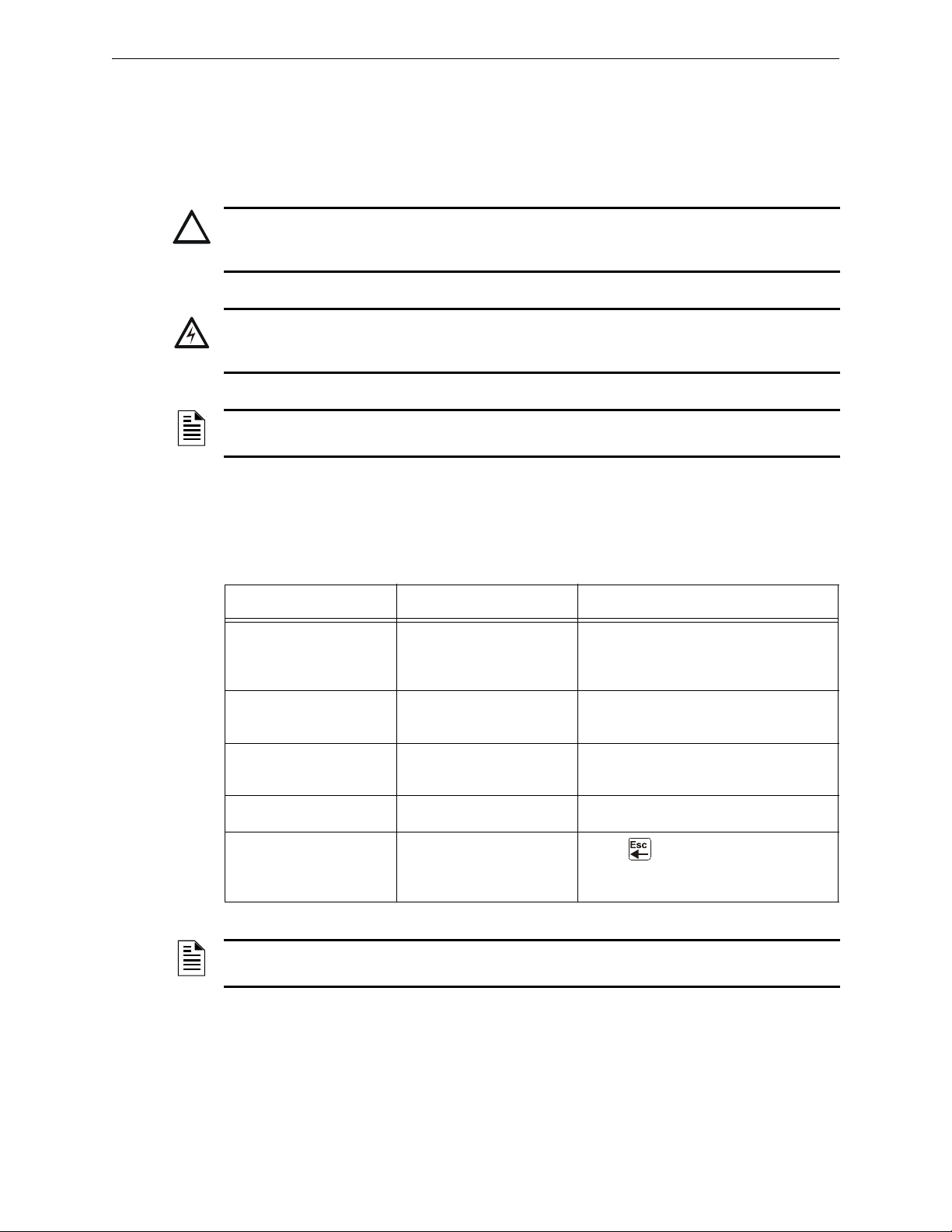
1.2.1 Cautions, Warning, and Notes
The following graphics appear in the manual to indicate a caution or a warning.
CAUTION:
Information about procedures that could cause programming errors, runtime errors, or equipment
damage.
WARNING:
Information about procedures that could cause irreversible damage to the control panel, irreversible
loss of programming data or personal injury.
NOTE: Information that highlights an important part of the preceding or subsequent text or
illustration.
1.2.2 Typographic Conventions
This manual uses the following conventions as listed below:
Table 1.2 Typographic Conventions in this Manual
When you see Specifies Example
the text as it appears in
text in small caps
text in quotes
bold text
italic text a specific document NFS2-640 Installation Manual
a graphic of the key
the LCD display or on the
control panel
a reference to a section or
an LCD menu screen
In body text, a number or
character that you enter
In a graphic, a key as it
appears on the control
panel
MARCH TIME is a selection that appears
in the LCD display; or Press the
key
“Status Change” specifies the Status
Change section or menu screen
Press 1; means to press the number
“1” on the keypad
Press means to press the Escape
key
ENTER
NOTE: The term NFS2-640 is used in this manual to refer to the NFS2-640 and NFS2-640E
unless otherwise noted.
8 NFS2-640/E Programming Manual — P/N 52742:L2 7/17/14
Page 9

About This Manual General Information
1.2.3 Supplemental Information
The table below provides a list of documents referenced in this manual, as well as documents for
selected other compatible devices. The document series chart (DOC-NOT) provides the current
document revision. A copy of this document is included in every shipment.
Compatible Conventional Devices (Non-addressable) Document Number
Device Compatibility Document 15378
Fire Alarm Control Panel (FACP) and Main Power Supply Installation Document Number
NFS2-640/E Installation, Operations, and Programming Manuals 52741, 52742, 52743
SLC Wiring Manual 51253
Note: For individual SLC Devices, refer to the SLC Wiring Manual
Off-line Programming Utility Document Number
Ver iFir e
Veri•Fire Medium Systems Help File
Cabinets & Chassis Document Number
CAB-3/CAB-4 Series Cabinet Installation Document 15330
Battery/Peripherals Enclosure Installation Document 50295
Power Supplies, Auxiliary Power Supplies & Battery Chargers Document Number
ACPS-610 Addressable Power Supply Manual 53018
ACPS-2406 Installation Manual 51304
APS-6R Instruction Manual 50702
APS2-6R Instruction Manual 53232
CHG-120 Battery Charger Manual 50641
FCPS-24 Field Charger/Power Supply Manual 50059
FCPS-24S Field Charger/Power Supply Manual (Sync) 51977
Networking Document Number
Noti•Fire•Net Manual, Network Version 4.0 & Higher 51584
High-Speed Noti•Fire•Net Manual 54013
HS-NCM Installation Document 54014
NCM-W/F Installation Document 51533
NCS Network Control Station Manual, Network Version 4.0 & Higher 51658
NCA-2 Network Control Annunciator Manual 52482
ONYXWorks™ Workstation Manuals 52305, 52306, 52307
System Components Document Number
DVC Digital Voice Command Manual 52411
DAL Device Reference Document 52410
DVC-RPU Manual 50107425-001
DVC-RPU UL Listing Document 50107424-001
DS-DB Digital Series Distribution Board and Amplifier Manual 53622
DAA2 and DAX Amplifiers Manual 53265
Annunciator Control System Manual 15842
Annunciator Fixed Module Manual 15048
®
Tools CD help file
VERIFIRE-TCD
VERIFIRE-CD
Table 1.3 Related Documentation (1 of 2)
NFS2-640/E Programming Manual — P/N 52742:L2 7/17/14 9
Page 10

General Information Introduction to the Control Panel
AFM-16A Annunciator Fixed Module Manual 15207
ACM-8R Annunciator Control Module Manual 15342
LCD-80 Manual 15037
LCD2-80 Manual 53242
FDU-80 Remote Annunciator Manual 51264
LDM Series Lamp Driver Annunciator Manual 15885
SCS Smoke Control Manual (Smoke and HVAC Control Station) 15712
FireVoice-25/50ZS & FireVoice 25/50ZST Manual 52290
FirstCommand Emergency Communication System LS10001-001NF-E
RPT-485W/RPT-485WF EIA-485 Annunciator Loop Repeater Manual 15640
DPI-232 Direct Panel Interface Manual 51499
TM-4 Installation Document (Reverse Polarity Transmitter) 51490
UDACT Manual (Universal Digital Alarm Communicator/Transmitter) 50050
UDACT-2 (Universal Digital Alarm Communicator/Transmitter) Listing Document 54089LD
UDACT-2 Manual (Universal Alarm Communicator/Transmitter) 54089
ACT-2 Installation Document 51118
RM-1 Series Remote Microphone Installation Document 51138
RA100Z Remote LED Annunciator Installation Document I56-0508
Table 1.3 Related Documentation (2 of 2)
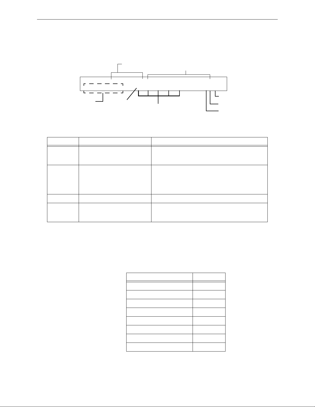
1.2.4 Shortcuts to Operating Functions
To the left of each program function, you’ll find a keypad shortcut, which contains
a series of keypad entries required to access the program function. All shortcuts
start with the control panel in normal operation.
For example, the keypad shortcut to the left shows how to enter the Read Status
function with the control panel in normal operation.
1.3 Introduction to the Control Panel
The NFS2-640 is an intelligent, field-programmable Fire Alarm Control Panel. Field-programming
the control panel lets you customize the fire alarm system by selecting and setting program options
for intelligent/addressable detectors and modules, and Notification Appliance Circuits (NACs).
This manual provides information for programming using the NFS2-640 keypad connected to the
control panel. VeriFire™ Tools must be used for programming if no keypad is used, or if a network
control annunciator is used as the keypad in either a network or standalone application. Refer to
VeriFire™ Tools for information on programming without the NF2S-640 keypad, and the NF2S-
640 Installation Manual and NCA-2 Manual for installation information.
For details on control panel operation, refer to the NFS2-640 Operations Manual.
The NF2S-640 provides two methods for field-programming the control panel:
• Using the built-in “Program Change” interface
• The VeriFire™ Tools Programming Utility
10 NFS2-640/E Programming Manual — P/N 52742:L2 7/17/14
Page 11

Features General Information
The benefits of each method are listed below:
Programming method Benefits Refer to
1.4 Features
Programming features include the following:
Program Change Speed and convenience of
putting the control panel on
line quickly (using the
Autoprogram function) and
changing programming
information.
VeriFire™ Tools
Programming Utility
Efficient means of creating
and editing programs that
require a lot of data entry.
Section “Programming” on
page 13
Product documentation &
Software help file
• Ease-of-use – Field program the control panel without needing special software skills.
• Autoprogram option – Automatically detects newly installed, addressable devices, allowing
quicker installation.
• Local programming – program directly from the control panel keypad to reduce installation
time.
• PC programming – input long data entry programming information on a PC; transfer
programming data between a PC and the control panel using VeriFire™ Tools programming
utility.
• Security – use passwords to control access to the control panel and protect memory.
• 80-Character (2x40) Liquid Crystal Display – view programming and device information on
the control panel.
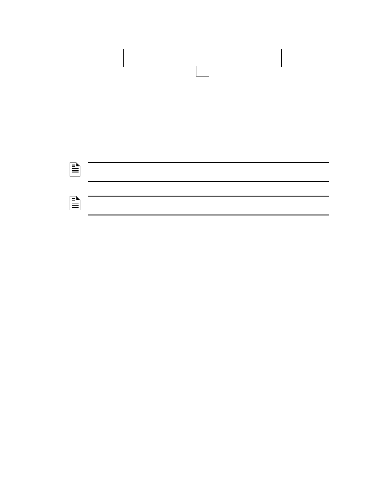
1.5 How to Enter a Password
The control panel provides two types of selectable passwords:
• Program Change
•Status Change
Listed below are uses and the factory-setting for each password type:
Table 1.4 Programming Passwords
Password
type
Program
Change
(high level)
Status Change
(low level)
Use to
Enter Program Change option to program
essential control panel functions, including basic
system functions and utility options.
Enter Status Change option to program minor
functions.
Factory
Setting
00000
11111
NFS2-640/E Programming Manual — P/N 52742:L2 7/17/14 11
Page 12
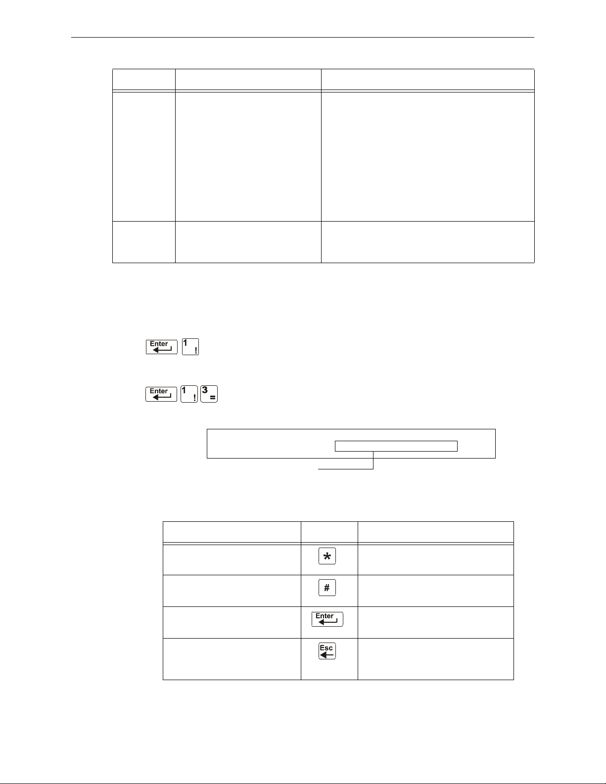
General Information How to Enter a Password
Enter password here (00000 or 11111)
ENTER PROG OR STAT PASSWORD, THEN ENTER.
(ESCAPE TO ABORT) _
From the “SYSTEM NORMAL” screen: Press ENTER, press 1 (the password screen will display).
Enter a password, then press
ENTER
Figure 1.1 Password Screen
In Program Change or Status Change, the control panel does the following:
• Activates the System Trouble relay
• Shuts off the panel sounder
• Flashes the
SYSTEM TROUBLE LED, which continues to flash while programming
For security purposes, passwords can be changed. To do so, follow the instructions in “Change a
Password (3=passwd)” on page 25.
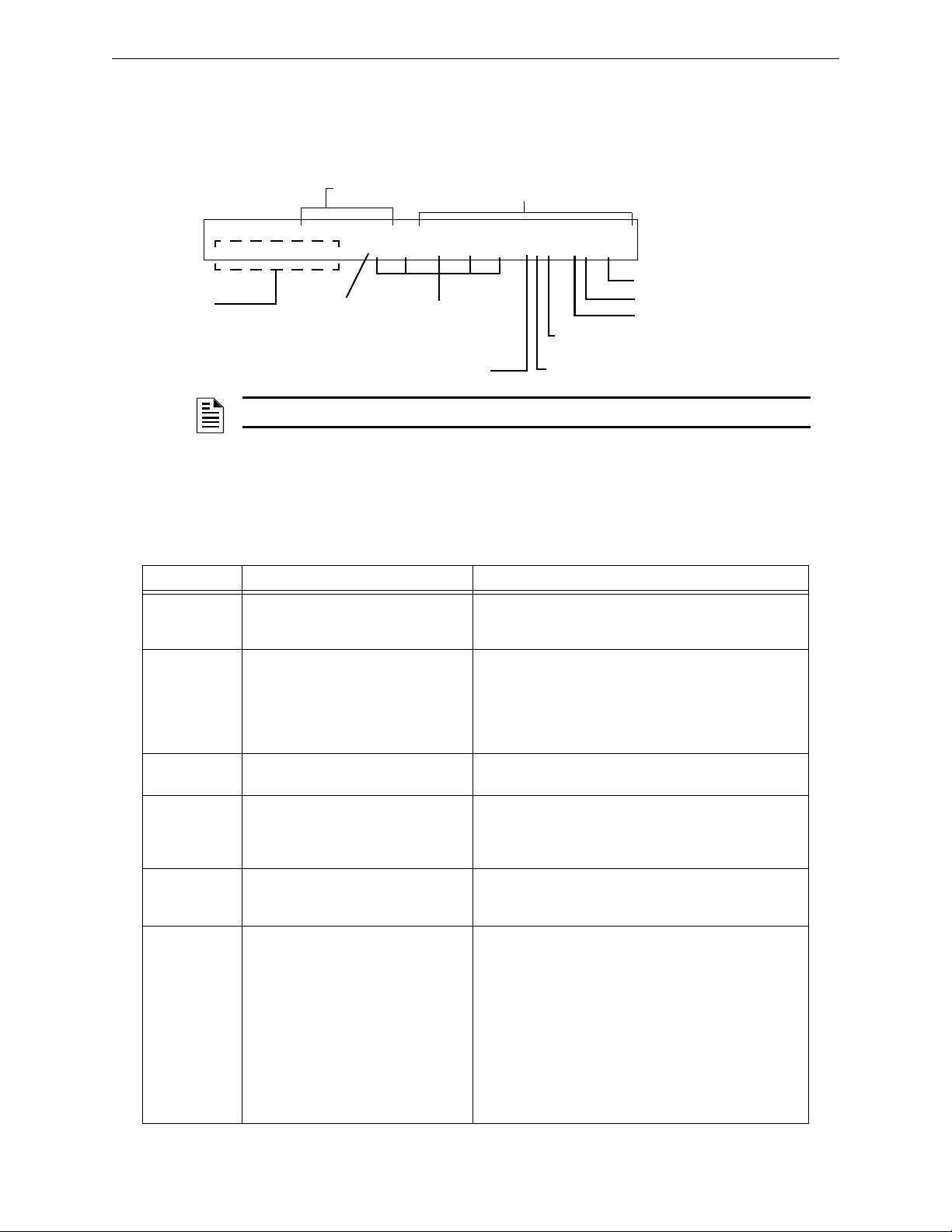
NOTE: The Read Status selection, which does not require a program password, is covered in
the NF2S-640 Operations Manual.
NOTE: The NF2S-640 continues to monitor and report alarms in programming mode, except in
autoprogramming.
12 NFS2-640/E Programming Manual — P/N 52742:L2 7/17/14
Page 13
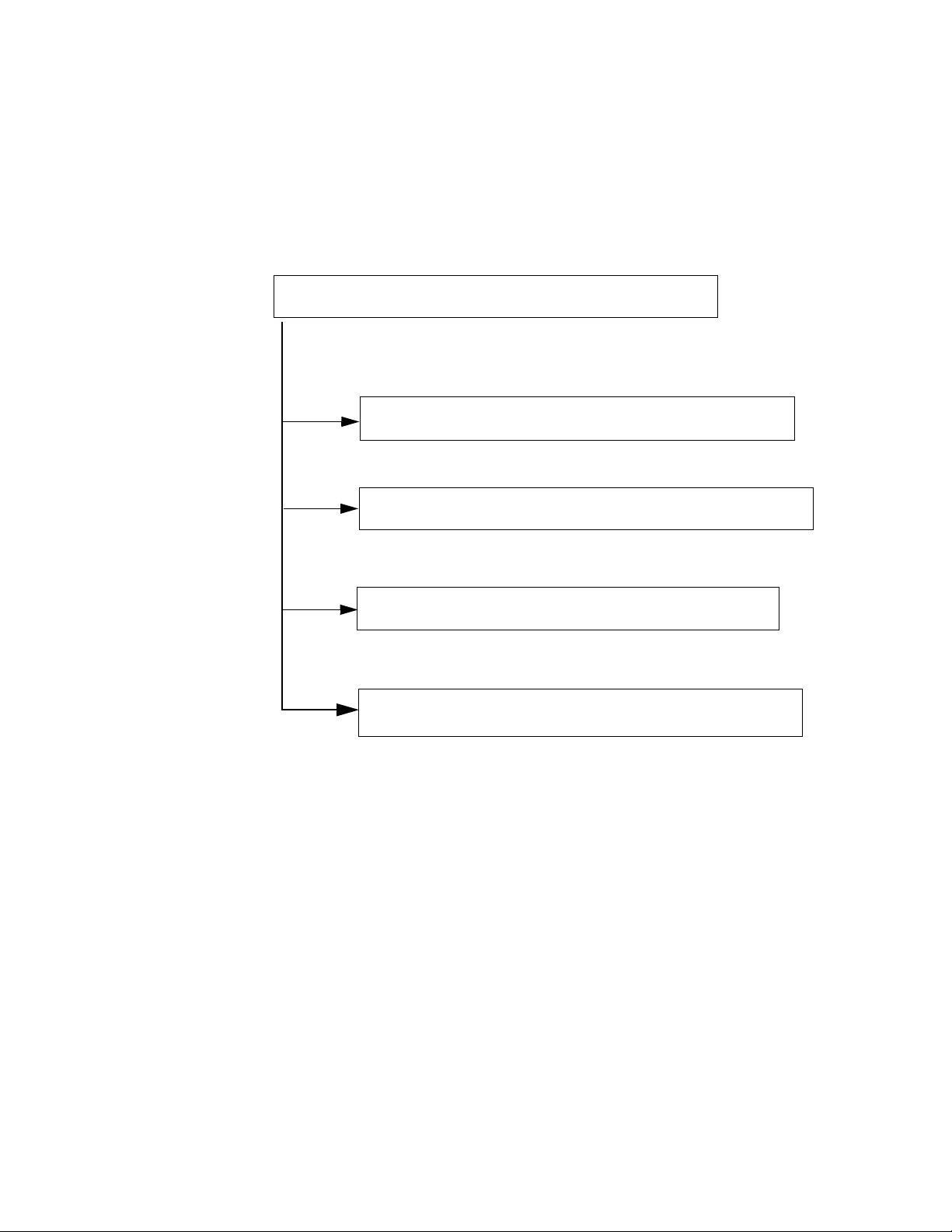
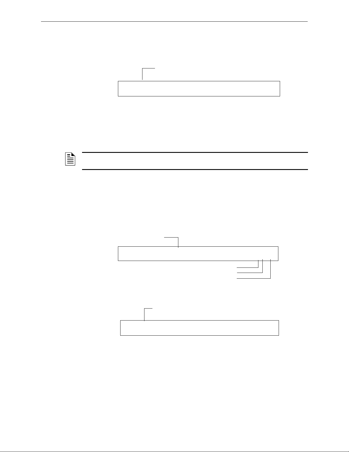
2.1 Overview
Choose one of the Program Change selections: 1, 2, 3 or 4
1 Basic Program options
3 Utility Program options
4 FlashScan Poll options
2 Network Program options
1=BASIC PROGRAM 2=NETWORK
3-UTILITY 4=FLASHSCAN POLL
0=CLR 1=AUTO 2=POINT 3=PASSWD 4=MESSAGE
5=ZONES 6=SPL FUNCT 7=SYSTEM 8=CHECK PRG
THRESHOLD CH.A:H, THRESHOLD CH.B:H
NODE: .000, STYLE7:Y, <ENTER>
REGION=0 TBL.REMIND=2 ALA.SCROLL=N
LOCAL CONTROL=0
FLASHSCAN L1DET L1MOD L2DET L2MOD
NYNY
Program Change is the programming level that lets you change the essential control panel
functions, such as point programming, changing passwords, changing system functions. Included
are four options: Basic Program, Network, FlashScan Poll, and Utility Program.
The structure of the Program Change option is shown below:
Section 2: Programming
This section contains instructions and sample screens for using the Programming selections:
Figure 2.1 Program Change Selections
• Basic Program The Basic Program lets you program essential functions, such as clearing
the program, Autoprogramming the system, programming points, and setting system
functions. Refer to “Basic Program” on page 14.
• Network Program The Network Program allows programming of network channel
thresholds, network node number, and wiring style.“The Network Program” on page 47.
• Utility Program The Utility Program screen provides selections for selecting a Trouble
Reminder per NFPA, a Region setting, and enabling or disabling local control of the
ACKNOWLEDGE/SCROLL DISPLAY, SIGNAL SILENCE, SYSTEM RESET and DRILL keys. Refer to
“The Utility Program” on page 48.
• FlashScan Poll The FlashScan Poll screen provides the option for selecting between CLIP
NFS2-640/E Programming Manual — P/N 52742:L2 7/17/14 13
(Classic Loop Interface Poll) and FlashScan Poll. Refer to “FlashScan Poll” on page 49.
Page 14
Programming How to Enter Programming
1=PROGRAMMING 2=READ STATUS ENTRY
(ESCAPE TO ABORT)
ENTER PROG OR STAT PASSWORD, THEN ENTER.
(ESCAPE TO ABORT) _
1=BASIC PROGRAM 2=NETWORK
3-UTILITY 4=FLASHSCAN POLL
0=CLR 1=AUTO 2=POINT 3=PASSWD 4=MESSAGE
5=ZONES 6=SPL FUNCT 7=SYSTEM 8=CHECK PRG
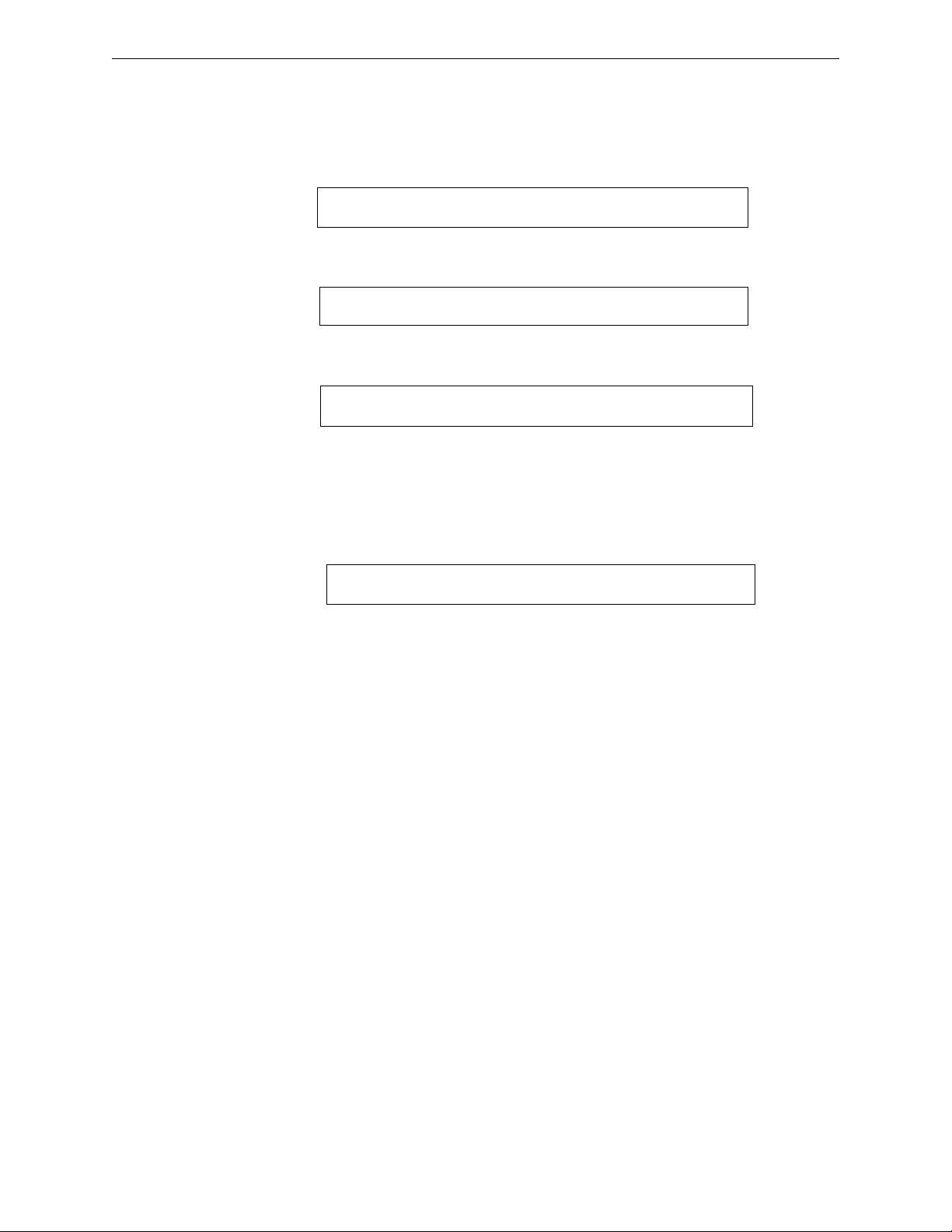
2.2 How to Enter Programming
To enter Program Change, follow these steps:
1. At the “SYSTEM NORMAL” screen, press the
“Entry” screen, as shown below:
2. At the “Entry” screen, press the 1 key. The control panel displays the “Enter Password” screen
as shown below:
3. Enter your Program Change password (See “How to Enter a Password” on page 11). The
control panel displays the “Program Change Selection” screen, as shown below:
4. Select a Program Change selection: 1, 2, 3 or 4.
2.3 Basic Program
From the “Program Change Selection” screen, press the 1 key to display the “Basic Program”
screen which provides nine (9) options as shown below:
ENTER key. The control panel displays the
Press the number of any one of the nine (9) options as detailed below
Option 0=CLR - Clears all existing user programming. For details, refer to How to Clear Memory
(0=
CLR) on page 15. Note: The user is prompted to double-check that this is what is really wanted.
Option 1=AUTO - Add or remove addressable devices to the control panel program. For details,
refer to How to Autoprogram the Control Panel (1=
AUTO) on page page 15.
Option 2=POINT - Modify or delete a point. For details, refer to “How to Modify or Delete a
Point (2=
POINT)” on page page 19.
Option 3=PASSWD - Change the Program Change or the Alter Status password. For details, refer
to “How to Change a Password (3=
PASSWORD)” on page page 25.
Option 4=MESSAGE - Edit the 40-character message that displays on the first line. For details,
refer to “How to Create a System Message (4=
MESSAGE)” on page page 26.
Option 5=ZONES - Edit the 20-character custom zone label for zones 01-99. For details, refer to
“How to Create a Custom Zone Label (5=
ZONE)” on page page 27.
Option 6=SPL FUNCT - Program Releasing Zones and Special Zones. For details, refer to “How
to Program Special Zones (6=
SPL FUNCT)” on page page 27.
Option 7=SYSTEM - Program Global System Functions. For details, refer to “How to Change
Global System Functions (7=
SYSTEM)” on page page 31.
Option 8=CHECK PRG - Check the program for errors. For details, refer to “How to Check the
Program for Errors (8=check prg)” on page 47.
14 NFS2-640/E Programming Manual — P/N 52742:L2 7/17/14
Page 15

Basic Program Programming
Program Change
Password
PRESS ENTER TO CLEAR ENTIRE PROGRAM
OR ESCAPE TO ABORT
Program Change
Password
2.3.1 Clear Memory (0=CLR)
The Clear option removes all programming information from control panel
memory. If installing the control panel for the first time, use option 0 to clear
control panel memory. To do so, follow these steps:
1. From the “Basic Program” screen, press the 0 (zero) key to display the Clear Program screen.
The control panel prompts for verification as shown below:
2. Press the
ENTER key to clear control panel memory or press the ESC key to exit the screen
without clearing.
2.3.2 Autoprogram the Control Panel (1=AUTO)
Purpose
The Autoprogram option identifies all addressable devices connected to the control panel. Devices
include addressable detectors and modules connected to SLC 1 or SLC 2, and NACs. You can use
the Autoprogram option to create a new program and add or remove devices. A summary of the
Autoprogram functions, when to use the functions, and where to find information on using the
functions is found below:
Autoprogram Function Control Panel Configuration Refer to...
Create a new program for
the control panel
Add one or more
SLC-connected detectors
and modules to an
existing program
Remove one or more
SLC-connected detectors
and modules from an
existing program
A new control panel or a control panel with no
existing program in memory.
A program exists in memory and you want to
add a detector or module to the existing
program—without modifying information for
existing detectors and modules.
A program exists in memory and you want to
remove an installed detector or module from
the existing program—without modifying
information for existing detectors and
modules.
“Create a New Program for the
Control Panel” on page 15
“Add a Device to the Program”
on page 16
“Remove a Device from the
Program” on page 17
View system defaults A program exists in memory and you want to
view system settings assigned during
Autoprogram, such as custom labels,
passwords, and so on.
Page 19 “Change Autoprogram
Default Value” to see the system
defaults
Create a New Program for the Control Panel
This section covers how to use the Autoprogram option to create a new
program for the control panel. The control panel will identify all addressable
detectors and modules connected to the SLC.
To create a new program for the control panel, follow these steps:
NFS2-640/E Programming Manual — P/N 52742:L2 7/17/14 15
Page 16
Programming Basic Program
AUTOPROGRAM PLEASE WAIT
L1:010Dets, 159Mods L2:159Dets, 159Mods
SB L1:000, L2:159 Bells: 04
ACCEPT ALL DEVICES Please Wait!!!
PROGRM SMOKE(PHOTO) DETECTOR ADDR 1D147
03 __ __ __ __A8P8** 1D147
1. Use the Clear option to clear program information from memory. For instructions on clearing
memory, refer to “How to Clear Memory (0=
NOTE: Once Step 1 is completed, Step 2 will cause the panel to assess whether a loop is
comprised of all FlashScan devices or not. If they are all FlashScan, autoprogramming will
change the loop setting to FlashScan if it was not already at that setting. If the devices are not all
FlashScan, autoprogramming will not make a change to the default setting of CLIP. (See
“FlashScan Poll” on page 49 for FlashScan settings.)
CLR)” on page page 15.
2. From the “Basic Program” screen, press the 1 key to start Autoprogram. While the control
panel scans the system to identify all SLC devices and NACs, it displays the following screen:
When the autoprogram is finished identifying SLC devices and NACs, it displays a summary
screen that gives a count of all the devices it has located. Refer to the following screen for an
example of this display.
SB represents detectors with B200 series sounder bases. Refer to VeriFire Tools for B200 sounder
base programming.
3. Press
ENTER. All devices are automatically accepted during initial autoprogramming. The
following screen displays briefly, followed by the
SYSTEM NORMAL screen.
To edit the autoprogramming default values for a point, refer to “How to Modify or Delete a Point
(2=
POINT)” on page page 19.
To edit the autoprogram default values assigned to all modules and detectors during
autoprogramming, refer to “Change Autoprogram Default Values” on page 18.
Add a Device to the Program
You can also use the Autoprogram option to add addressable devices to the control panel program.
NOTE: When using the Autoprogram option with an existing program, the control panel does not
change program information for installed and programmed devices. However, it will assess
whether a loop contains all FlashScan devices and change the loop setting to FlashScan if
necessary.
The following steps describe how to add a new detector at SLC address 1D147 with 10 detectors in
the existing program:
1. Physically install the addressable detector to SLC 1 at address 147 (for instructions, refer to the
NF2S-640 Installation Manual and the installation document that comes with the detector).
2. From the “Basic Program” screen, press the 1 key to start Autoprogram. The Autoprogram
Prompt screen appears in the LCD display as the control panel identifies addressable devices.
When finished identifying addressable devices, the control panel displays information for the
new detector at SLC address 1D147 on the LCD display as shown below:
16 NFS2-640/E Programming Manual — P/N 52742:L2 7/17/14
Page 17
Basic Program Programming
Note that the number of detectors increases (in this example
from 10 to 11) to show the addition of the detector to SLC 1.
L1:011Dets, 159Mods L2:159Dets, 159Mods
SB Bells: 04
Type Code
SLC loop number
D (detector) or M (module)
Three-digit address (001-159)
PROGRM SMOKE (ION) DETECTOR ADDR 1D133
DEVICE NOT ANSWERING DELETE FR MEM?1D133
Note that the number of detectors decreases (from 11 to
10) to show the removal of the detector from SLC 1.
L1:010Dets, 159Mods L2:159Dets, 159Mods
SB Bells: 04
3. Press the ENTER key to add detector 147 to the program with the default program information.
If you want to change the default information, use the programming keys to do so, then press
the
ENTER key to add detector 147 to the program.
The Autoprogram Summary screen appears. You can verify addition of the detector to the
program by noting the new count of detectors as shown below:
4. Press the
ENTER key, then press the esc key to save the program in memory and return to the
“Basic Program” screen).
Remove a Device from the Program
You can also use the Autoprogram option to remove addressable detectors and modules from the
control panel program.
NOTE: When using the Autoprogram option with an existing program, the control panel does not
change program information for installed and programmed devices.
The following steps describe how to delete a detector at SLC address 1D133 with 11 detectors
connected to SLC 1 in the existing program:
1. Disconnect and remove the detector from SLC 1 at address 1D133.
2. From the “Basic Program” screen, press the 1 key to start Autoprogram. The Autoprogram
Prompt screen displays while the control panel identifies addressable devices.
3. When finished identifying addressable devices, the control panel displays a screen, indicating a
missing detector at SLC address 1D133 as shown below:
4. Press the
ENTER key to delete detector 1D133 from the program.
The Autoprogram Summary screen appears. You can verify removal of the detector from the
program by noting the new count of detectors as shown below:
5. Press the
ENTER key, then press the ESC key to save the program in memory and return to the
“Basic Program” screen.
NFS2-640/E Programming Manual — P/N 52742:L2 7/17/14 17
Page 18

Programming Basic Program
NOTE: The FCM-1-REL has an inherent two second
delay, which must be factored into the DELAY TIME
and SOK (soak time) entries.
Change Autoprogram Default Values
To assign system default values from the basic program screen, Press 0 (clear), then press 1
(autoprogram). Refer to the chart below for default values and how to modify them.
Table 2.1 Autoprogram Defaults (1 of 2)
Function Default Values To Alter, refer to
Software
Zones
01-99
F0 PRG PRESIGNAL FUNCT PRESIGNAL DELAY
Releasing
Zones
R0-R9
Default custom label “Zone xx” where xx is the
number of the zone
Note: Zone 00 is reserved for a general alarm.
DELAY=180 PAS=NO F00
PRG RELEASE FUNCT RELEASE CONTROL
DELAY=00 ABORT=ULI CROSS=N SOK=0000
“How to Create a Custom Zone Label (5=
“F0 (Presignal/PAS) The Presignal screen provides fields for
changing the delay time or PAS. For details on Presignal
selections, refer to “Presignal and PAS Time” on page 92. From
the Special Function Change screen, press the F key, then
press the 0 key to display the Presignal Function screen.” on
page 29
“R0-R9 (Releasing Functions) The Releasing Function screen
provides fields for changing releasing functions: Delay Timer,
Abort Switch, Cross Zone, and Soak Timer. For details on
releasing applications, refer to “NFPA Releasing Applications”
on page 61.” on page 29 and “How to Program a Releasing
Zone” on page 61.
ZONE)” on page 27
F5 and F6 PRG TIME FUNCTION TIME CONTROL
ON=**:** OFF=**:** DAYS=********
F7 PRG HOLIDAY FUNCTION **/** **/** **/**
**/** **/** **/** **/** **/** **/**
F8 PRG CODING FUNCTION CODE TYPE
MARCH TIME F08
F9 PRE-ALARM FUNCT ALERT
F09
System
Parameters
Passwords Default programming passwords are:
SYSTEM
NORMAL
message
SIL INH=0000 AUTO=0077
0 VERIFY=30 USA TIME
TERM=N AC_DLY=Y LocT BLINK=01 ST=4 ACS=N
Program Change=00000
Status Change=11111
(YOUR CUSTOM SYSTEM MESSAGE HERE)
SYSTEM NORMAL 10:23A 041508 Tue
A message, along with the current day, time, and
date, that displays on the second line of the LCD
display during normal operation.
“F5-F6 (Time Control Functions) The Time Control screen
provides fields for changing the start time, stop time, or days of
the week. For details on time selections, refer to “Time Control
Zones” on page 93. From the Special Function Change screen,
select F5 or F6 to display the Time Control screen:” on page 30
“F7 (Holiday) The Holiday screen provides fields for specifying
up to nine holiday dates. For details on holiday selections, refer
to “Time Control Zones” on page 93. From the Special Function
Change screen, press F7 to display the Holiday screen:” on
page 30
“F8 (Coding Function) The Coding Function screen provides
fields for specifying one of the following coding functions: March
Time, Two-stage, California, Temporal, Two-Stage Canada (3
minutes), Two-Stage Canada (5 minutes), Two-Stage Canada
Manual, System Sensor Strobe, Gentex Strobe, and Wheelock
Strobe. For details on selecting coding functions, refer to
“Coding Functions for NACS” on page 93. From the Special
Function Change screen, press F8 to display the Coding
Function screen:” on page 30
“F9 (Pre-Alarm) The Pre-Alarm screen provides fields for
programming the Alert or Action Pre-Alarm functions. For
details on Pre-Alarm selections, refer to “Pre-Alarm” on
page 99. From the Special Function Change screen, press F9
to display the Pre-Alarm screen:” on page 31
“How to Change Global System Functions (7=
page 31
“How to Change a Password (3=
Note: The second line, “SYSTEM NORMAL”, is a standard
system message that you cannot change
PASSWD)” on page page 25
SYSTEM)” on
18 NFS2-640/E Programming Manual — P/N 52742:L2 7/17/14
Page 19
Basic Program Programming
Program Change
Password
POINT PROG. 1=MODIFY POINT
2=DELETE POINT
Press for module point
SLC number
Three-digit address (001-159)
E - press the
ENTER key
Press for detector point.
SLC number
Three-digit address (001-159)
Press for NAC
Modify Point Screen
Delete Point Screen
E - press the
ENTER key
POINT PROG. ENTER:DETECTOR=*,LDAAA,E
MODULE=#,LMAAA,E OUTPUT CKT=&,A-A,E
E - press the
ENTER key
Two-digit address for
NAC (01-04)
DELETE POINT. ENTER:DETECTOR=*,LDAAA,E
MODULE=#,LMAAA,E OUTPUT CKT=&,A-A,E
Table 2.1 Autoprogram Defaults (2 of 2)
Function Default Values To Alter, refer to
System
Message
IP
ACCESS
DCC Mode Default setting is N, no DCC participation. “The Utility Program” on page 48
(YOUR CUSTOM SYSTEM MESSAGE HERE)
SYSTEM NORMAL 10:23A 041508 Tue
The first line of the LCD display contains 40 blank
characters for a custom message.
Default setting is zero (0), IP Access not enabled. “The Utility Program” on page 48
“How to Create a System Message (4=
page 26
MESSAGE)” on page
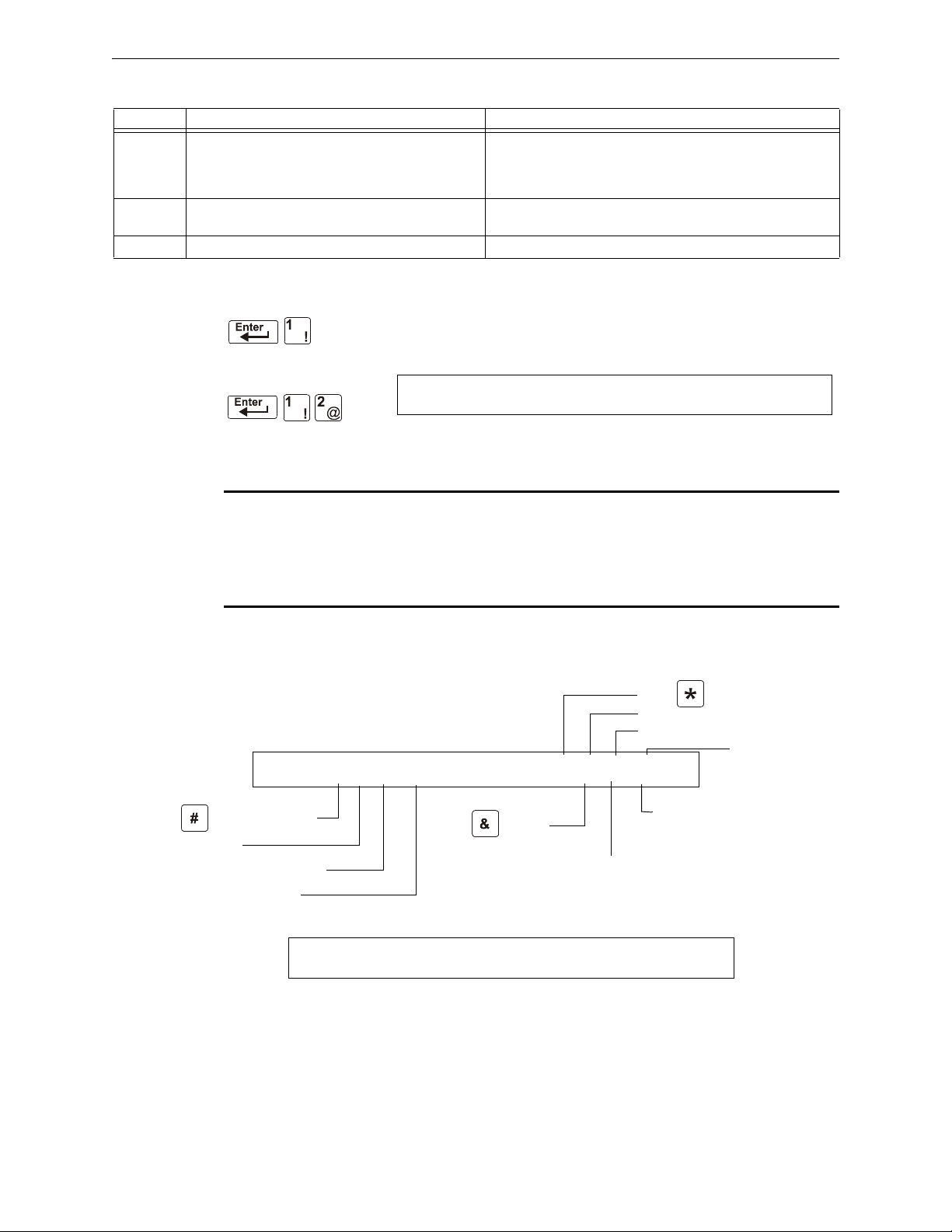
2.3.3 Modify or Delete a Point (2=POINT)
After programming all SLC-connected devices into the system, you can
modify or delete points. From the “Basic Program” screen, press the 2 key to
display the Point Programming screen:
To modify a point for a detector, module, or NAC: press the 1 key to display
the “Modify Point” screen.
NOTE: When programming points, take the following into design consideration:
Each general zone must be dedicated to a single event type (i.e. Fire, MN, Security, etc.)
Map inputs only to general zones designed for the input’s event type. For example, map mass
notification devices to general zones designed for mass notification.
Outputs can be mapped to multiple general zones that are dedicated to different event types. For
instance, a single output can be mapped to an MN general zone and a Fire general zone.
To delete a point for a detector, module, or NAC: press the 2 key to display the “Delete Point”
screen.
NFS2-640/E Programming Manual — P/N 52742:L2 7/17/14 19
Page 20
Programming Basic Program
12 spaces for extended custom label
PROGRM SMOKE(PHOTO) DETECTOR ADDR 1D101
03 __ __ __ __A8P8AV 1D101
Blinking Type Code selection
CBE list
(five zones)
D (detector)
SLC address (001-159)
20-character user-editable custom label (in
this example, autoprogramming has used
the first 19 and left a space at the end.)
SLC Loop number
Alarm sensitivity level
Pre-alarm sensitivity level
Cooperative multi-detector
mode indicator
Alarm verification setting
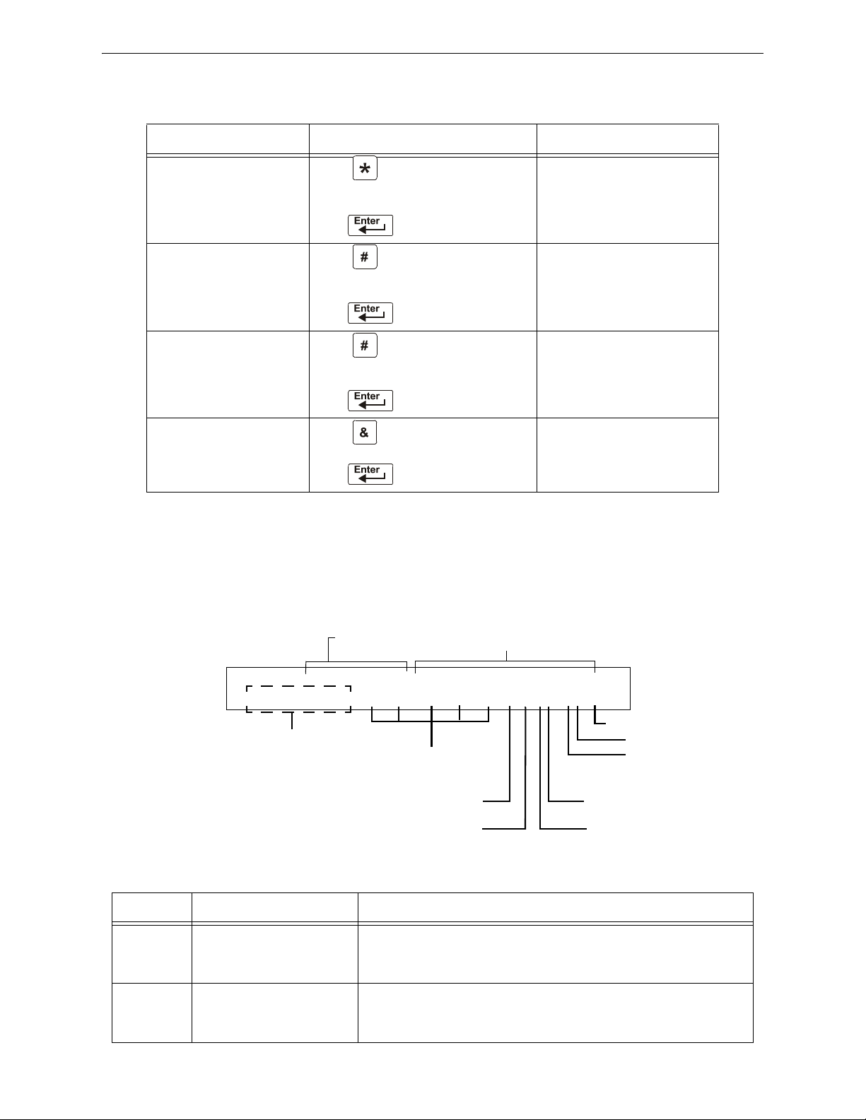
The Modify Point and Delete Point screens let you edit or delete points for a detector, a monitor or
control module, or NAC. To select a point, follow these steps:
To select Do the following Refer to
an addressable
detector
an addressable monitor
module
an addressable control
module
a NAC Press
Press
Type the SLC number (1 or 2) and
detector (D) and address (001-159)
Press
Press
Type the SLC number (1 or 2) and module
(M) and address (001-159)
Press
Press
Type the SLC number (1 or 2) and module
(M) and address (001-159)
Press
Type the NAC address (01-04)
Press
The next four sections describe how to program the points selected.
Modify an Addressable Detector Point
This section contains a sample detector programming screen, detector default selection, and
instructions for modifying a detector point. Autoprogram default values for a detector are shown:
“Modify an Addressable Detector
Point” on page 20.
“Modify an Addressable Monitor
Module Point” on page 22.
“Modify an Addressable Control
Module Point” on page 23.
“Modify NAC Points” on page 24.
Field Description Set as Follows
Type Code Detector function
Custom
Label
20 NFS2-640/E Programming Manual — P/N 52742:L2 7/17/14
Table 2.2 Detector Program Values
specification SMOKE(PHOTO) in example.
20 character custom label. Change by placing the cursor into the first space of the field using the arrow
Press the
Type Code selections. See F.4.2 on page 112 for lists and descriptions.
keys, then typing the descriptor. DETECTOR ADDR 1D101 is the
autoprogram default custom label for the detector at address 101 on SLC 1.
NEXT or PREVIOUS Selection keys to scroll through valid detector
Page 21

Basic Program Programming
Zone 01 (Heat detectors)
Zone 02 (Ion detectors)
Zone 03 (Photo detectors, Beam detectors)
Zone 04 (Laser detectors)
Zone 05 (Multisensor)
A8 (Photo)
A6 (Ion)
A6 (Laser)
A5 (Multisensor)
P8 (Photo)
P6 (Ion)
P6 (Laser)
P5 (Multisensor)
Table 2.2 Detector Program Values
Field Description Set as Follows
Extended
Label
12 character custom label
extension.
CBE List Five zones can be listed - one
zone, Z03, is shown in the
example. Up to 4 more could
be added to this detector.
Alarm
Sensitivity
The alarm sensitivity level,
with 9 the least sensitive
alarm level and 1 the most
sensitive alarm level.
Pre-alarm
level
Shows the Pre-Alarm level
setting—a number between 0
and 9—as follows:
0 – no Pre-Alarm
1 – self optimizing
2 – most sensitive Pre-Alarm
level
9 – least sensitive Pre-Alarm
level
See “Custom Label” above.
Note that spaces must be input by the user, including any space necessary
between the custom and extended label fields. An 80-column printout will
run the two fields together.
Zones can be changed or added to the CBE list by placing the cursor in the
zone field using arrow keys, then typing.
Defaults:
Refer to Table C.2 on page 101 for settings. Select by placing the cursor in
the field using the arrow keys, then either pressing the
NEXT or PREVIOUS
keys to make the selection, or typing the value.
Defaults:
Refer to Table C.2 on page 101 for settings. Select by placing the cursor in
the field using the arrow keys, then either pressing the
NEXT or PREVIOUS
keys to make the selection, or typing the value.
Defaults:
Cooperative
Multidetector
mode
Alarm
verification
Indicates the cooperative
multi-detector mode (A in the
example).
Indicates the alarm
verification setting (V in the
example).
Select by placing the cursor in the field using the arrow keys, then either
pressing the
NEXT or PREVIOUS keys to make the selection, or typing the
value.
* = OFF (Default)
A combines the detector's alarm decision with the next address above
B combines the detector's alarm decision with the next address below
C combines the detector's alarm decision with the next address above and
the next address below
Indicates Alarm Verification (V=on, *=off). Select by placing the cursor in the
field using the arrow keys, then pressing the
NEXT or PREVIOUS keys to make
the selection. Refer to “Interpreting a Detector Status Display or
Maintenance Report” on page 104 for more information on the alarm
verification feature.
Note: Do not use this setting when an alarm activation requires activation of
two or more automatic detection devices.
NFS2-640/E Programming Manual — P/N 52742:L2 7/17/14 21
Page 22
Programming Basic Program
Default zone
Blinking Type Code selection
CBE list
(five zones)
12 spaces for extended
custom label
SLC number (1 or 2)
M (module)
SLC address (001-159)
PROGRAM MONITOR WESTERN ENTRANCE AND
HALLWAY 09 __ __ __ __ 2M101
20-character user-editable custom label.
Modify an Addressable Monitor Module Point
When you select a point address, the control panel returns a screen that displays information about
the point. Below is an example of information for a monitor module (2M101) in the LCD display:
Table 2.3 Modifying Monitor Module Programming Selections
Field Description Set as Follows
Type Code Monitor Module function specification
-
MONITOR in example.
Custom Label 20 character custom label. Change by placing the cursor into the first space of the field
Extended Label 12 character custom label extension. See “Custom Label” above.
CBE List Five zones can be listed - one zone,
Z09, is shown in the example. Up to 4
more could be added to this module.
Press the
valid monitor module Type Code selections. Lists and
descriptions are in See Table F.2 on page 114.
using the arrow keys, then typing the descriptor.
Note: Spaces must be input by the user, including any space
necessary between the custom and extended label fields. An
80-column printout will run the two fields together.
Zones can be changed or added to the CBE list by placing the
cursor in the zone field using arrow keys, then typing.
See Table 2.4 on page 22 for defaults.
NEXT or PREVIOUS Selection keys to scroll through
When finished modifying a point, press the
ENTER key; then press the NEXT or PREVIOUS key to
select another point.
Monitor Module Default Zone Assignments
Listing of the monitor module address range and the default zone assignment for each range:
Table 2.4 Monitor Module Default Zones
Monitor Module Address Zone Default
01 through 19 Z04
20 through 39 Z05
40 through 59 Z06
60 through 79 Z07
80 through 99 Z08
100 through 119 Z09
120 through 139 Z10
140 through 159 Z11
22 NFS2-640/E Programming Manual — P/N 52742:L2 7/17/14
Page 23
Basic Program Programming
Walk Test Selection: *=off
(default); W=selected
Silenceable: O =selected; *=off (default)
Default zone
Blinking Type Code selection
CBE list
(five zones)
12 spaces for extended
custom label
SLC number (1 or 2)
M (module)
SLC address (001-159)
Switch Inhibit: I=selected; *=off (default)
PROGRAM CONTROL MODULE CONTROL 2M101
00 __ __ __ __ IOW 2M101
20-character user-editable custom label
NOTE: On a control module, the default zone is always set to Zone 00 (general alarm).
Modify an Addressable Control Module Point
When you select a point address for modification, the control panel returns a screen that displays
information about the point. For example, the illustration below shows sample information for a
control module (2M101) in the LCD display.
To modify a point, follow these steps. A blinking cursor indicates the selected field.
1. From the programming screen, use the arrow keys to move to a field that you want to modify.
See below for descriptions and settings.
Table 2.5 Modifying Control Module Programming Selections (1 of 2)
Field Description Set as follows:
Type Code Specifies the function of the control
module
Custom Label 20 character custom label. Change by placing the cursor into the first space of the
Extended
Label
CBE list Up to five software zones can be
Switch Inhibit Specifies if an operator can manually
Silenceable Specifies if an operator can manually
12 character custom label extension. See “Custom Label” above.
entered to define the output responses
of the control module based on
various initiating conditions (events)
activate an output
silence an activated output
Press the
through valid control module Type Code selections (listed
in Table F.3 on page 115)
field using the arrow keys, then typing the descriptor.
Note: Spaces must be input by the user, including any
space necessary between the custom and extended label
fields. An 80-column printout will run the two fields
together.
Type the number of up to five zones, including E0-E9, F0F9, L0-L9, R0-R9, and zones 00-99. The first zone default
is Z00 (general alarm).
Type one of the following entries.
I = Switch Inhibit enabled
* = no switch inhibit (default for all but releasing circuits)
Type one of the following entries.
* = output nonsilenceable
F = silenceable, resound by fire alarm
U = silenceable, resound by supervisory alarm
B = silenceable, resound by security alarm
T = silenceable, resound by trouble
O = silenceable, does not resound
If the “Strobe” Type ID is used with System Sensor,
Gentex or Wheelock Strobe synchronization,“*” will
silence the horn portion only, and resound will occur only
by fire alarm. F, U, B, T, or O will silence the entire circuit,
and resound will occur according to the above definitions.
NEXT or PREVIOUS Selection keys to scroll
NFS2-640/E Programming Manual — P/N 52742:L2 7/17/14 23
Page 24

Programming Basic Program
The address of a NAC connected
through NAC 1 (B01), NAC 2
(B02), NAC 3 (B03), or NAC 4
(B04)
Five zones for CBE list; the default zone
selection is 00 (general alarm)
Default zone
12 spaces for extended
custom label
Switch Inhibit: I=selected; *=off (default)
Walk Test Selection: *=off (default);
W=selected
Silenceable: O=selected; *=off (default)
Type Code
20-character user-editable custom label
PROGRAM CONTROL Notification Dev No1
00 __ __ __ __ *OW B01
Table 2.5 Modifying Control Module Programming Selections (2 of 2)
Field Description Set as follows:
Walk Test Specifies if outputs sound during Walk
Te st
Type one of the following entries.
W = devices sound (Basic Walk Test)
* = devices do not sound (Silent Walk Test) (default)
2. When finished modifying a point, press the ENTER key; then press the NEXT or PREVIOUS key to
select another point.
Modify NAC Points
Modifying NACs (four NACs on the NFS2-640) is like modifying control modules—except for the
Type Code and device address.
To modify a point, follow these steps. A blinking cursor indicates the selected field.
1. From the programming screen, use the arrow keys to move to a field that you want to modify
and refer to information below for descriptions and settings.
Table 2.6 Modifying a NAC Programming Selections (1 of 2)
Field Description Set as follows:
Type Code Specifies the function of the NAC. Press the
through the NAC Type Code selections (listed in
Table F.4 on page 116)
Custom Label 20 character custom label. Change by placing the cursor into the first space of the
field using the arrow keys, then typing the descriptor.
Note: Spaces must be input by the user, including any
space necessary between the custom and extended label
fields. An 80-column printout will run the two fields
together.
Extended
Label
CBE zones Specifies up to five software zones to
Switch Inhibit Specifies if an operator can manually
12 character custom label extension. See “Custom Label” above.
define the output responses of the
NAC based on various initiating
conditions (events)
activate an output
Type the numbers of up to five zones, including E0-E9,
F0-F9, L0-L9, R0-R9, and zones 00-99. The first zone
default is 00 (general alarm)
Type in one of the following values.
I = Switch Inhibit enabled
* = Switch Inhibit disabled (default for all but releasing
circuits)
NEXT or PREVIOUS Selection keys to scroll
24 NFS2-640/E Programming Manual — P/N 52742:L2 7/17/14
Page 25
Basic Program Programming
Program Change
Password
CHANGE PASSWORD *,NNNNN,E=PROGRAM
#,NNNNN, E=STATUS
Entry area for new password
Table 2.6 Modifying a NAC Programming Selections (2 of 2)
Field Description Set as follows:
Silenceable Specifies if an operator can manually
silence an activated output
Walk Test Specifies if outputs sound during Walk
Te st
Type in one of the following values.
* = output nonsilenceable
F = silenceable, resound by fire alarm
U = silenceable, resound by supervisory alarm
B = silenceable, resound by security alarm
T = silenceable, resound by trouble
O = silenceable, does not resound
If the “Strobe” Type ID is used with System Sensor,
Gentex or Wheelock Strobe synchronization,“*” will
silence the horn portion only, and resound will occur only
by fire alarm. F, U, B, T, or O will silence the entire circuit,
and resound will occur according to the above definitions.
Type in one of the following values.
W = devices sound (Basic Walk Test) - default
* = devices do not sound (Silent Walk Test)
2. When finished modifying a point, press the ENTER key; then press the NEXT or PREVIOUS key to
select another point.
2.3.4 Change a Password (3=PASSWD)
Password Change lets you select a custom Program Change (high level) or
Status Change (low level) password. From the “Basic Program” screen, press
the 3 key to display the “Change Password” screen.
.
To change a password, follow the instructions below:
Table 2.7 Changing a Password
To Pr ess T hen
Change the Program Change
password
Change the Status Change
password
Save the password The Verify Password screen appears.
Leave the Change Password
screen without changing a
password
Enter the new Program Change
password. Use five digits, no characters.
Enter the new Status Change password.
Use five digits, no characters.
Press
ENTER to verify.
The Basic Program screen appears.
NFS2-640/E Programming Manual — P/N 52742:L2 7/17/14 25
Page 26
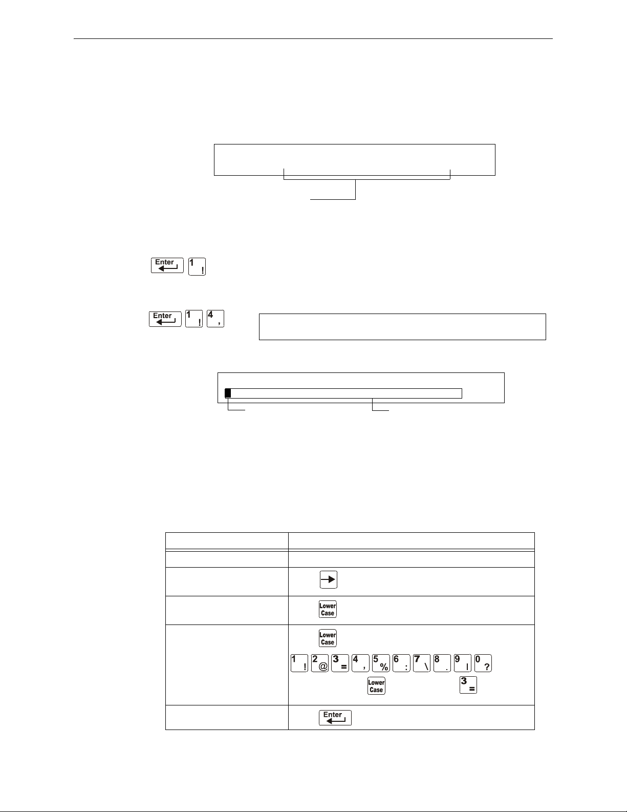
Programming Basic Program
INCORRECT PASSWORD
PROGRAM: 9066-21F5-7D78-5FA4-6163
Code
Program Change
Password
YOUR CUSTOM MESSAGE HERE
SYSTEM NORMAL 02:24P 041508 Tue
Blinking cursor prompt
Message change area
SYSTEM NORMAL
A Forgotten Password?
If a password is entered incorrectly, the panel will respond by displaying an
message and a code. The programmer may hit escape and reenter the password correctly. However,
if the password has been forgotten, record the code and contact Notifier. After proper
authentication, the original password can be determined by deciphering the code. An example of an
INCORRECT PASSWORD display is given below:
2.3.5 Create a System Message (4=MESSAGE)
The Message option lets you create a 40-character custom System Message
that displays on the first line of the “
below:
From the “Basic Program” screen, press the 4 key to display the “System Message Change” screen:
SYSTEM NORMAL’ screen as shown
INCORRECT PASSWORD
To create the system message, follow these guidelines:
• Enter one character at a time, indicated by the blinking cursor on the second line of the
display.
• Enter up to 40 characters maximum.
Instructions for entering characters in the Message Change screen:
Table 2.8 Creating Messages
To Do this
Change a blinking character Enter a character from the keypad
Move to the next character
Enter lower case characters
Enter additional characters !
@ = , % : \ . I ?
Save the new message
Press
Press , then press the character of your choice.
Press , then press a number key as follows:
For example, press , then press the
a “=” character.
Press
3 ( ) key to enter
26 NFS2-640/E Programming Manual — P/N 52742:L2 7/17/14
Page 27

Basic Program Programming
Program Change
Password
CHANGE ZONE LABEL SELECT ZONE 01-99:
ENTER UP TO 20 CHAR
blinking cursor prompt
Custom zone label (characters 21-40)
Program Change
Password
SPECIAL FUNCTION: F0=PRESIG R0-R9=REL
F5-F6=TIME F7=HOL F8=CODE F9=PRE-ALARM
2.3.6 Create a Custom Zone Label (5=ZONE)
The Zone option lets you change the custom label assigned to zones 1-99.
From the “Basic Program” screen, press the 5 key to display the “Zone
Change” screen as shown below:
The zone number displays in the first line, characters 39 and 40. When changing a zone label,
follow these guidelines.
• For single-digit numbers, enter a leading zero before the digit.
• Enter an alphanumeric zone label into line 2, characters 21–40.
To change a custom label for a zone, follow these instructions:
Table 2.9 Create or Change a Custom Zone Label
To Do t his
Change a zone label Enter a new zone label from the keypad.
Save the zone label in memory Press .
The program stores the zone label in memory and
displays the Zone Change screen with all fields blank.
Leave the Zone Change screen
without changing a zone label
Press .
The display returns to the Program Change screen.
2.3.7 Program Special Zones (6=SPL FUNCT)
The Special Zone Change option lets you change the program for Special
Zones F0-F9, Releasing Zones R0-R9, FA (Verification), FB (Custom drill
zone) or FC (CO Alarm). From the “Basic Program” screen, press the 6 key to
display the “Special Function Change” screen as shown below:
.
Special Zone Descriptions
Descriptions for each Special Zone that appears in the “Special Function Change” screen are
detailed below:
NOTE: Special Zones F0-F9 appear in the CBE list of a device as ZF0-ZF9. For example, if you
list F0 for a detector, one of the five zones in the CBE list of the detector will display as ZF0.
NFS2-640/E Programming Manual — P/N 52742:L2 7/17/14 27
Page 28

Programming Basic Program
Table 2.10 Summary of Special Zones
Special Zone Lets you
F0=
PRESIG Select a Presignal Delay Timer and select PAS (Positive Alarm
Sequence)
F5-F6=
TIME Specify Time Control functions such as the start time, stop time, or
days of the week
F7=
HOL Specify up to nine holiday dates. An F7-programmed device
activates on the specified holiday dates
F8=
CODE Specify one of the following coding function selections: March Time,
Temporal, California, Two-Stage, Two-Stage Canada (3 minute or 5
minute), Two-Stage Canada Manual, System Sensor Strobes,
Gentex Strobes, or Wheelock Strobes. F8 only takes effect if you
program one or more NACs to F8
F9=
PRE-ALARM Select a Pre-Alarm level: Alert or Action
FA (ZF10*) Turn on when detector in verification mode. This is a fixed point and
is not programmable
FB (ZF16*) Turn on if custom drill set to Y and the panel in Drill mode
FC (ZF18*) Turn on when a CO alarm occurs
FD (ZF20*) Turns on when a mass notification alarm occurs (Not applicable for
FirstCommand applications)
FE (ZF21*) Turns on when a mass notification supervisory occurs
FF (ZF22*) Turns on when a mass notification trouble occurs
NOTE: Special Function Zones FA through FF are not field programmable.
R0-R9=
REL Program up to ten Releasing Zones, each with a selection for a
Delay Timer, an Abort Switch, a Cross Zone selection, or a Soak
Timer
* VeriFire Tools settings
Mass Notification
When used for mass notification, special zones ZF20, ZF21, and ZF22 can be used to signal the
MN event.
NOTE: During local or network Walk Test, activating a Mass Notification device will activate
associated special function zones according to CBE programming and simulate a Mass
Notification event. Any network nodes, zones, or devices not participating in Walk Test will not
participate in the simulated Mass Notification event.
Special Zones F1-F4
The control panel also provides four Special Zones, F1-F4, which are outputs that do not appear on
the Special Function Change screen. You can program Special Zones F1 to F4 into the CBE of an
output device. Descriptions of F1, F2, F3, and F4 are detailed below:
To view the status of Special Functions F1-F4, use the Read Status function (refer to the NFS2-640
Operations Manual).
Table 2.11 Special Output Functions F1-F4 (1 of 2)
Special Function Specifies
F1 (Trouble less AC) An output programmed to turn on/off if a system trouble—other
than an AC power loss—occurs
28 NFS2-640/E Programming Manual — P/N 52742:L2 7/17/14
Page 29
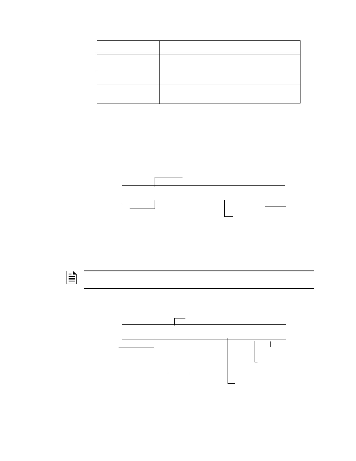
Basic Program Programming
Presignal delay time:
60-180 seconds
PAS selection: YES (PAS selected)
or NO (PAS not selected)
Presignal programming status banner
Presignal
(zone F0)
PRG PRESIGNAL FUNCT PRESIGNAL DELAY
DELAY=180 PAS=NO F00
Delay Timer for
releasing application:
1-60 seconds or 00
(no delay)
Releasing Zone programming status banner
Abort Switch: a thee-letter Abort switch
Type Code (ULI, IRI, NYC, or AHJ)
Cross Zone option: specifies type of
Cross Zone: N (none), Y, Z, or H
Soak Timer option:0000
(not used) or delay time
(0001-9999 seconds)
Releasing zone
(R0 shown)
PRG RELEASE FUNCT RELEASE CONTROL
DELAY=00 ABORT=ULI CROSS=N SOK=0000 R00
Table 2.11 Special Output Functions F1-F4 (2 of 2)
Special Function Specifies
F2 (AC Trouble) An output programmed to turn on/off if an AC power loss or a
brownout condition occurs
F3 (Security) An output programmed to turn on/off if a Security input activates
F4 (Supervisory) An output programmed to turn on/off if a Supervisory input
activates
Selecting Special Zones
Select Special Zones by entering the Special Zone letter and number (for example, F0, R0, and so
on) from the Special Function Change screen. The following sections show sample screens that
display when you select a Special Zone.
F0 (Presignal/PAS) The Presignal screen provides fields for changing the delay time or PAS. For
details on Presignal selections, refer to “Presignal and PAS Time” on page 92. From the Special
Function Change screen, press the F key, then press the 0 key to display the Presignal Function
screen.
NFS2-640/E Programming Manual — P/N 52742:L2 7/17/14 29
R0-R9 (Releasing Functions) The Releasing Function screen provides fields for changing
releasing functions: Delay Timer, Abort
Switch, Cross Zone, and Soak Timer. For details on
releasing applications, refer to “NFPA Releasing Applications” on page 61.
NOTE: The FCM-1-REL has an inherent two second delay, which must be factored into the
DELAY TIME and SOK (soak time) entries.
From the Special Function Change screen, select a function (R0-R9) to display the Releasing
Function screen:
Page 30
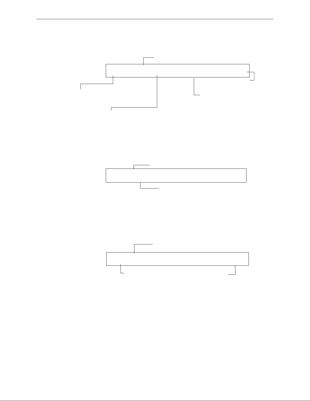
Programming Basic Program
Time Control programming status banner
Time Control zone
(F5 shown)
Eighth day-of-week selection (H) that
specifies when time control settings
take effect. Press the
NEXT or PREVIOUS
key to toggle each selection.
ON time: Start Time for Time Control
function (in 24-hour time) that must
precede the OFF time.
OFF time: End time for Time Control
function (in 24-hour time) that must
be later than the ON time.
PRG TIME FUNCTION TIME CONTROL
ON=08:00 OFF=12:00 DAYS=SMTWTFSH F05
Holiday programming status banner
Nine fields for selecting holidays:
USA time (mm/dd)
PRG HOLIDAY FUNC **/** **/** **/**
**/** **/** **/** **/** **/** **/**
Coding Function selection (refer to
“Coding Functions for NACS” on
page 93)
Coding Function programming status banner
Coding Function
(Zone F8)
PRG CODING FUNCTION CODE TYPE
MARCH TIME F08
F5-F6 (Time Control Functions) The Time Control screen provides fields for changing the start
time, stop time, or days of the week. For details on time selections, refer to “Time Control Zones”
on page 93. From the Special Function Change screen, select F5 or F6 to display the Time Control
screen:
F7 (Holiday) The Holiday screen provides fields for specifying up to nine holiday dates. For
details on holiday selections, refer to “Time Control Zones” on page 93. From the Special Function
Change screen, press F7 to display the Holiday screen:
30 NFS2-640/E Programming Manual — P/N 52742:L2 7/17/14
F8 (Coding Function) The Coding Function screen provides fields for specifying one of the
following coding functions: March Time, Two-stage, California, Temporal, Two-Stage Canada (3
minutes), Two-Stage Canada (5 minutes), Two-Stage Canada Manual, System Sensor Strobe,
Gentex Strobe, and Wheelock Strobe. For details on selecting coding functions, refer to “Coding
Functions for NACS” on page 93. From the Special Function Change screen, press F8 to display
the Coding Function screen:
Page 31
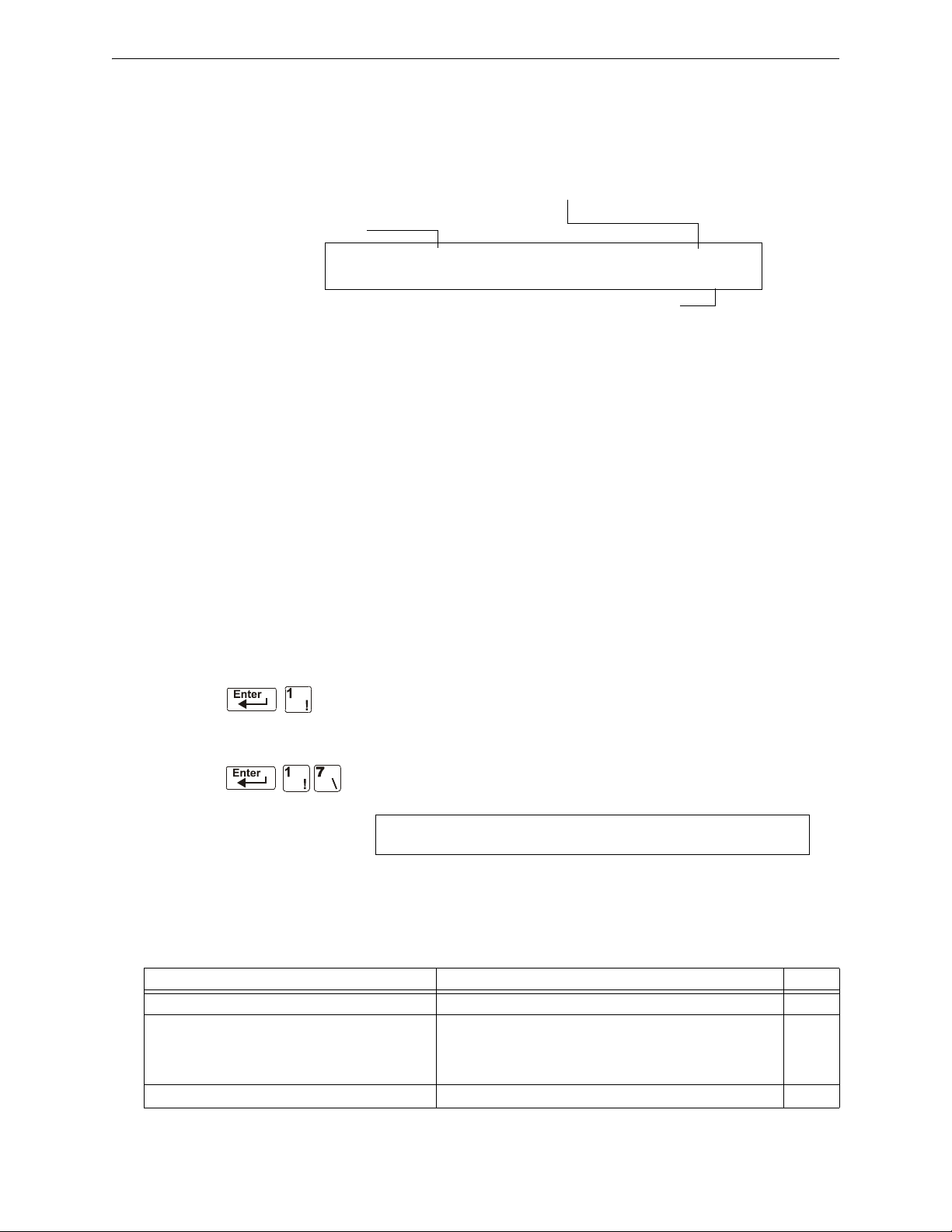
Basic Program Programming
ACTION or ALERT Pre-Alarm level: press the NEXT or PREVIOUS
key to toggle between
ALERT and ACTION. For details on selections,
refer to “Pre-Alarm” on page 99)
Pre-Alarm (Zone F9)
PreAlarm programming
status banner
PRG PRE-ALARM FUNCT ALERT
F09
Program Change
Password
SIL INH=000 AUTO=000 VERIFY=30 USA TIME
TERM=N AC_DLY=Y LocT BLINK=01 ST=4 ACS=N
F9 (Pre-Alarm) The Pre-Alarm screen provides fields for programming the Alert or Action
Pre-Alarm functions. For details on Pre-Alarm selections, refer to “Pre-Alarm” on page 99. From
the Special Function Change screen, press F9 to display the Pre-Alarm screen:
FA (Verification) Turn on when detector in verification mode. This is a fixed point and is not
programmable.
FB (Custom drill zone) Turn on if custom drill set to Y and the panel in Drill mode.
FC (CO Alarm) Turn on in the event a CO alarm is present on an FCO-851 detector or monitor
module with a CO monitor type code.
FA, FB and FC can map to output point only. It can be mapped to the output device as a CBE using
either panel key pad or VeriFire tools. But the custom drill option (Yes or No) is only programmed
by VeriFire tools.
FD (MN Alarm) Turn on when an MN Alarm occurs on the fire panel. (Not applicable for
FirstCommand applications).
FE (MN Supervisory) Turn on when an MN Supervisory occurs on the fire panel.
FF (MN Trouble) Turn on when an MN Trouble occurs on the fire panel.
2.3.8 Change Global System Functions (7=SYSTEM)
The System option lets you select settings for global system functions that
apply to all programmed devices and zones. For instance, selecting an Alarm
Verification Timer for 30 seconds means that all initiating devices selected
for Alarm Verification use a 30-second timer. From the “Basic Program”
screen, press the 7 key to display the “System Function” screen as shown
below:
Global System Functions
Settings for global system functions:
Table 2.12 Settings for Global Systems Functions (1 of 2)
System Function Setting Default
SIL INH (Silence Inhibit Timer) 0 to 300 seconds 000
AUTO (Auto Silence Timer) - After the time delay
expires, functions like pressing the SIGNAL
SILENCE key, silencing active outputs programmed
as silenceable.
VERIFY (Alarm Verification Timer) 0 to 60 seconds* 60
000 (none); 600 to 900 seconds 000
NFS2-640/E Programming Manual — P/N 52742:L2 7/17/14 31
Page 32

Programming Basic Program
Table 2.12 Settings for Global Systems Functions (2 of 2)
System Function Setting Default
USA TIME USA time (mm/dd/yy) or
EUR time (dd/mm/yy)
Press the
(European) time changes to 24-hour time format and date
format.
TERM - Allows supervision for devices connected
to TB11, i.e., FDU-80.
AC_DLY** AC delay – delays loss of AC reporting for 3 hours.
LocX - One of three operating modes of PC or
terminal connected to the control panel through
TB12 on the CPU2-640.
Note: For a complete list of functions, refer to the
NFS2-640 Operations Manual.
BLINK - Addressable SLC device LED blink. Select from 00 to 16.
ST - The NFPA wiring style used for the SLC. 6=Style 6 SLC wiring
ACS - Use ACS Selection Groups (Refer to
“Annunciator Options” on page 33).
*This value can not exceed 30 seconds for ULC installations.
**The onboard trouble relay will activate (TB4 on the NFS2-640 CPU) and TM-4s will report according to this setting. UDACTs
and UDACT-2s are notified immediately of AC failure by the panel, regardless of the panel’s delay setting. Once the UDACT
or UDACT-2 receives notification, it operates according to its own programmed AC Fail Delay reporting schedule.
N = no supervision
Y = supervision enabled
Y=AC delay; N=no AC delay
LocT -(terminal connected to control panel and located in
same room).
LocM -(same as LocT but requires password).
RemT -(terminal connected through a modem for Read Status
only).
(00 = no blink, 01 = blink every poll, 02 = blink every 2nd poll,
03 = blink every 3rd poll up to 16 = blink every 16th poll).
Note that this setting affects FlashScan modules only.
4=Style 4 SLC wiring
N or Y N
NEXT or PREVIOUS key to change. Note that
USA
N
Y
LocT
01
4
Example: AC Failure occurs at 1:00 p.m. on a panel with an AC_DLY setting of Y (3 hours). The UDACT/UDACT-2 is set for
notification after 1 hour.
1:00 p.m. - AC Failure. Panel notifies UDACT/UDACT-2. Panel and UDACT/UDACT-2 timers begin countdown to report
time.
2:00 p.m. - UDACT/UDACT-2 reports.
4:00 p.m. - TM-4 reports, TB4 trouble relay activates.
The ACPS-610 and ACPS-2406 power supplies must be set to an AC Delay value of 0 (zero) when used with this panel.
32 NFS2-640/E Programming Manual — P/N 52742:L2 7/17/14
Page 33

Basic Program Programming
ACS Address
A1-A11
ACS Selection Group (A-M; 0-9)
or *=not selected
If UDACT=2: The UDACT is installed with Detector Maintenance Reporting. A24-A31 are
pre-programmed to send control panel status to the UDACT. Only the first 100 detectors on
Loop 1 and Loop 2 participate in Detector Maintenance Reporting. For pre-programmed
point addressing, refer to associated table for Groups P through W on the following pages.
UDACT-2 does not support this option.
If UDACT=1: The UDACT or UDACT-2 is installed. Addresses A20-A32 are available to
send control panel status to the UDACT (software release #UDACT02.1 or higher) or the
UDACT-2
If UDACT=0: No UDACT or UDACT-2 is installed. The control panel displays the
Annunciator Selection 3 & 4 screen for addresses A20-A32.
ACS Address
A12-A19
ANNUN SELECTION1 A1=* A2=* A3=* A4=*
A5=* A6=* A7=* A8=* A9=* A10=* A11=*
ANNUN SELECTION2 A12=* A13=* A14=*
A15=* A16=* A17=* A18=* A19=* UDACT=0
ACS Address (A1)
ACS Selection Group (H)
ANNUN SELECTION1 A1=H A2=I A3=* A4=*
A5=8 A6=* A7=* A8=* A9=* A10=* A11=*
Annunciator Options
NOTE: An ACM-24AT or AEM-24AT LED point must be programmed as a dedicated visual
indicator for a mass notification or CO event. This is not required for displayless systems.
Use Annunciator Selection screens to select information that will display on the ACS annunciators.
(Table 2.13 on page 34 contains the ACS display selections.) Setting
Function” screen displays the Annunciator Selection 1 screen, address A1-A11. Press enter to
display Annunciator Selection 2 screen, address A12 - A19:
ACS=Y from the “System
Enter “N” (ACS Selection Group N) for a TM-4 module used for remote station communication.
Enter “O” (ACS Selection Group O) for a TM-4 used as a municipal box trip. This will provide a
“Master Box” trouble message at the panel.
Refer to page page 41 for further information on Group N and Group O.
ACS Selection Group Example
An example of a screen listing ACS Selection Groups (H, I and M):
Annunciator selections for addresses A1, A2 and A3 (addresses A4-A11 not selected).
• Annunciators set to Address 1 display the status of detectors 1-64 (Group H) on SLC 1
NFS2-640/E Programming Manual — P/N 52742:L2 7/17/14 33
• Annunciators set to Address 2 display the status of detectors 1-64 (Group I) on SLC 2
Page 34

Programming Basic Program
Annunciation Points
The control panel’s annunciation points are divided into 23 ACS selection groups of 64 points each.
The table below contains a list of these groups, what an annunciator displays when a group is
selected, and where to locate a definition of the 64 points within the group.
Table 2.13 ACS Selection Groups (1 of 2)
ACS Selection
Group
A 8 System points & Zones 1 - 56 Table 2.14 on page 35
B Zones 57 - 99, 9 F Zones, 8 R Zones, 4 NACs Table 2.15 on page 36
C Loop 1, Modules 1 - 64 Table 2.16 on page 36
D Loop 2, Modules 1 - 64 Table 2.17 on page 37
E Loop 1, Modules 65 - 128 Table 2.18 on page 37
F Loop 2, Modules 65 - 128 Table 2.19 on page 37
G Loop 1, Modules 129 - 159 (1 unused point)
H Loop 1, Detectors 1 - 64 Table 2.21 on page 38
I Loop 2, Detectors 1 - 64 Table 2.22 on page 39
J Loop 1, Detectors 65 - 128 Table 2.23 on page 39
K Loop 2, Detectors 65 - 128 Table 2.24 on page 39
L Loop 1, Detectors 129 - 159 (1 unused point)
M Programmable for use with FireVoice NFV-25/50ZS
N 8 System Points & Zones 1-56 “ACS Selection Group N” on
O 8 System Points & Zones 1-56 “ACS Selection Group O” on
P* Loop 1, Modules 65-100
Q* Loop 2, modules 65-100
R* Loop 1, detectors 15-46 (Each detector occupies 2
S* Loop 2, Detectors 15-46 (Each detector occupies 2
T* Loop 1 Detectors 47-78 (Each detector occupies 2
U* Loop 2, Detectors 47-78 (Each detector occupies 2
V* Loop 1, Detectors 79-100 (Each detector occupies 2
W* Loop 2, Detectors 79-100 (Each detector occupies 2
*Group only available with UDACT programmed as option 2.
Annunciator Display Refer to
Table 2.20 on page 37
Loop 2, Modules 129 - 159 (1 unused point)
Table 2.25 on page 40
Loop 2, Detectors 129 - 159 (1 unused point)
Table 2.26 on page 41
or FirstCommand
page 41
page 41
Table 2.27 on page 42
Loop 1, Detectors 1-14 (Each detector occupies 2
points)
Table 2.28 on page 43
Loop 2, Detectors 1-14 (Each detector occupies 2
points)
Table 2.29 on page 44
points)
Table 2.30 on page 44
points)
Table 2.31 on page 45
points)
Table 2.32 on page 45
points)
Table 2.33 on page 46
points)
Table 2.34 on page 46
points)
1 Programmable Annunciator #1 See Note
2 Programmable Annunciator #2 See Note
3 Programmable Annunciator #3 See Note
34 NFS2-640/E Programming Manual — P/N 52742:L2 7/17/14
Page 35

Basic Program Programming
Table 2.13 ACS Selection Groups (2 of 2)
ACS Selection
Group
4 Programmable Annunciator #4 See Note
5 Programmable Annunciator #5 See Note
6 Programmable Annunciator #6 See Note
7 Programmable Annunciator #7 See Note
8 Programmable Annunciator #8 See Note
9 Programmable Annunciator #9 See Note
0 Programmable Annunciator #10 See Note
Annunciator Display Refer to
NOTE: Refer to the VeriFire™ Tools programming utility for programming these annunciators.
ACS Selection Group A:
Table 2.14 ACS Group A
Point Type Red LED Yellow LED
1 Input System Alarm System Trouble Acknowledge
2 Output Not Used Signal Silenced Alarm Silence
3 Output Not Used Program Mode System Reset
4 Output Not Used Supervisory Drill
5 Output NAC #1 Active NAC Trouble Control NAC #1
6 Input Security P/A Maint. Alert Not Used
7 Input Not Used Low Battery Not Used
8 Input Not Used AC Fail Not Used
Switch Function
*
9 Input Zone 1 Active Zone 1 Trouble Not Used
10 Input Zone 2 Active Zone 2 Trouble Not Used
11 Input Zone 3 Active Zone 3 Trouble Not Used
to to (see note) to (see note)
64 Input Zone 56 Active Zone 56 Trouble Not Used
* Pressing the switch button when the Switch Function is “Not Used” will cause the associated LED to
stop blinking. This is a local acknowledgement at the annunciator only: no message is sent to the panel.
NOTE: Point number to Zone number relationship is sequential. To determine Point to Zone
relationship subtract 8 from Point number to arrive at Zone number.
NFS2-640/E Programming Manual — P/N 52742:L2 7/17/14 35
Page 36

Programming Basic Program
ACS Selection Group B:
Table 2.15 ACS Group B
Point Type Red LED Yellow LED Switch Function*
1 Input Zone 57 Active Zone 57 Trouble Not Used
2 Input Zone 58 Active Zone 58 Trouble Not Used
3 Input Zone 59 Active Zone 59 Trouble Not Used
to to (see note 1) to (see note 1)
43 Input Zone 99 Active Zone 99 Trouble Not Used
44 Output Zone F1 Active Zone F1 Trouble Not Used
45 Output Zone F2 Active Zone F2 Trouble Not Used
to to (see note 2) to (see note 2)
52 Output Zone F9 Active Zone F9 Trouble Not Used
53 Release Ckt #0 Zone R0 Active Zone R0 Trouble Not Used
54 Release Ckt #1 Zone R1 Active Zone R1 Trouble Not Used
to to to (see note 2) to (see note 2)
60 Release Ckt #7 Zone R7 Active Zone R7 Trouble Not Used
61 NAC Output NAC B01 Active NAC B01 Trouble Controls NAC B01
62 NAC Output NAC B02 Active NAC B02 Trouble Controls NAC B02
63 NAC Output NAC B03 Active NAC B03 Trouble Controls NAC B03
64 NAC Output NAC B04 Active NAC B04 Trouble Controls NAC B04
* Pressing the switch button when the Switch Function is “Not Used” will cause the associated LED to stop
blinking. This is a local acknowledgement at the annunciator only: no message is sent to the panel.
NOTE:
1. Point number to Zone number relationship is sequential. To determine Point to Zone
relationship, add 56 to Point number to arrive at Zone number.
2. Point number to Zone number relationship is sequential; therefore, point 48 is zone F5 and
point 57 is zone R4.
ACS Selection Group C (SLC #1, Modules 1-64):
Table 2.16 ACS Group C
Point Type Red LED Yellow LED Switch Function
1 Input or Output Module 001 Active Module 001 Trouble Controls Output Module
2 Input or Output Module 002 Active Module 002 Trouble Controls Output Module
3 Input or Output Module 003 Active Module 003 Trouble Controls Output Module
to to (see note) to (see note)
64 Input or Output Module 064 Active Module 064 Trouble Controls Output Module
NOTE: Point number to Module number relationship is sequential; therefore, point 48 is
Module 048.
36 NFS2-640/E Programming Manual — P/N 52742:L2 7/17/14
Page 37

Basic Program Programming
ACS Selection Group D (SLC #2, Modules 1-64):
Table 2.17 ACS Group D
Point Type Red LED Yellow LED Switch Function
1 Input or Output Module 001 Active Module 001 Trouble Controls Output Module
2 Input or Output Module 002 Active Module 002 Trouble Controls Output Module
3 Input or Output Module 003 Active Module 003 Trouble Controls Output Module
to to (see note) to (see note)
64 Input or Output Module 064 Active Module 064 Trouble Controls Output Module
NOTE: Point number to Module number relationship is sequential; therefore, point 48 is
Module 048.
ACS Selection Group E (SLC #1, Modules 65-128):
Table 2.18 ACS Group E
Point Type Red LED Yellow LED Switch Function
1 Input or Output Module 065 Active Module 065 Trouble Controls Output Module
2 Input or Output Module 066 Active Module 066 Trouble Controls Output Module
3 Input or Output Module 067 Active Module 067 Trouble Controls Output Module
to to (see note) to (see note)
64 Input or Output Module 128 Active Module 128 Trouble Controls Output Module
NOTE: Point number to Module number relationship is sequential. To determine Point to Module
relationship add 64 to Point number to arrive at Module number.
ACS Selection Group F (SLC #2, Modules 65-128):
Table 2.19 ACS Group F
Point Type Red LED Yellow LED Switch Function
1 Input or Output Module 065 Active Module 065 Trouble Controls Output Module
2 Input or Output Module 066 Active Module 066 Trouble Controls Output Module
3 Input or Output Module 067 Active Module 067 Trouble Controls Output Module
to to (see note) to (see note)
64 Input or Output Module 128 Active Module 128 Trouble Controls Output Module
NOTE: Point number to Module number relationship is sequential. To determine Point to Module
relationship add 64 to Point number to arrive at Module number.
ACS Selection Group G (SLC #1 and #2, Modules 129-159):
Table 2.20 ACS Group G (1 of 2)
Point Type Red LED Yellow LED Switch Function
1 Output SLC 1, Module 129 Active SLC 1, Module 129 Trouble Controls SLC 1, Module 129
2 Output SLC 1, Module 130 Active SLC 1, Module 130 Trouble Controls SLC 1, Module 130
NFS2-640/E Programming Manual — P/N 52742:L2 7/17/14 37
Page 38

Programming Basic Program
Table 2.20 ACS Group G (2 of 2)
Point Type Red LED Yellow LED Switch Function
3 Output SLC 1, Module 131 Active SLC 1, Module 131 Trouble Controls SLC 1, Module 131
to to (see note 1) to (see note 1)
31 Output SLC 1, Module 159 Active SLC 1, Module 159 Trouble Controls SLC 1, Module 159
32 Not Used
33 Output SLC 2, Module 129 Active SLC 2, Module 129 Trouble Controls SLC 2, Module 129
34 Output SLC 2, Module 130 Active SLC 2, Module 130 Trouble Controls SLC 2, Module 130
35 Output SLC 2, Module 131 Active SLC 2, Module 131 Trouble Controls SLC 2, Module 131
to (see note 2) to (see note 2)
63 Output SLC 2, Module 159 Active SLC 2, Module 159 Trouble Controls SLC 2, Module 159
64 Not Used
NOTE:
1. Point number to Module number relationship is sequential. To determine Point to Module
relationship add 128 to Point number to arrive at Module number.
2. Point number to Module number relationship is sequential. To determine Point to Module
relationship add 96 to Point number to arrive at Module number.
ACS Selection Group H (SLC #1, Detectors 1-64):
Table 2.21 ACS Group H
Point Type Red LED Yellow LED Switch Function*
1 Input Detector 001 Alarm Detector 001 Trouble Not Used
2 Input Detector 002 Alarm Detector 002 Trouble Not Used
3 Input Detector 003 Alarm Detector 003 Trouble Not Used
to to (see note) to (see note)
64 Input Detector 064 Alarm Detector 064 Trouble Not Used
* Pressing the switch button when the Switch Function is “Not Used” will cause the associated LED to
stop blinking. This is a local acknowledgement at the annunciator only: no message is sent to the panel.
NOTE: Point number to Detector number relationship is sequential; therefore, point 48 is
Detector 048.
38 NFS2-640/E Programming Manual — P/N 52742:L2 7/17/14
Page 39
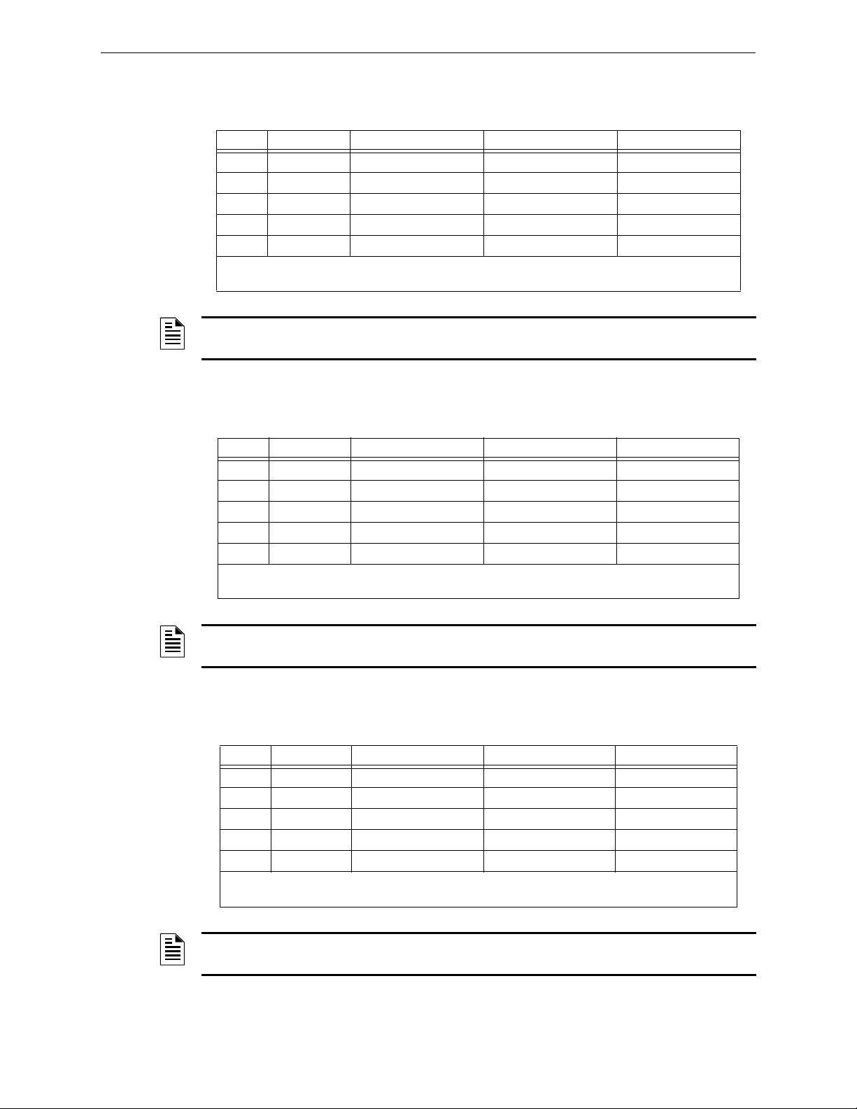
Basic Program Programming
ACS Selection Group I (SLC #2, Detectors 1-64):
Table 2.22 ACS Group I
Point Type Red LED Yellow LED Switch Function*
1 Input Detector 001 Alarm Detector 001 Trouble
2 Input Detector 002 Alarm Detector 002 Trouble
3 Input Detector 003 Alarm Detector 003 Trouble
to to (see note) to (see note)
64 Input Detector 064 Alarm Detector 064 Trouble
* Pressing the switch button when the Switch Function is “Not Used” will cause the associated LED to
stop blinking. This is a local acknowledgement at the annunciator only: no message is sent to the panel.
NOTE: Point number to Detector number relationship is sequential; therefore, point 48 is
Detector 048.
Not Used
Not Used
Not Used
Not Used
ACS Selection Group J (SLC #1, Detectors 65-128):
Table 2.23 ACS Group J
Point Type Red LED Yellow LED Switch Function*
1 Input Detector 065 Alarm Detector 065 Trouble Not Used
2 Input Detector 066 Alarm Detector 066 Trouble Not Used
3 Input Detector 067 Alarm Detector 067 Trouble Not Used
to to (see note) to (see note)
64 Input Detector 128 Alarm Detector 128 Trouble Not Used
* Pressing the switch button when the Switch Function is “Not Used” will cause the associated LED to
stop blinking. This is a local acknowledgement at the annunciator only: no message is sent to the panel.
NOTE: Point number to Detector number relationship is sequential. To determine Point to
Detector relationship add 64 to Point number to arrive at Detector number.
ACS Selection Group K (SLC #2, Detectors 65-128):
Table 2.24 ACS Group K
Point Type Red LED Yellow LED Switch Function*
1 Input Detector 065 Alarm Detector 065 Trouble Not Used
2 Input Detector 066 Alarm Detector 066 Trouble Not Used
3 Input Detector 067 Alarm Detector 067 Trouble Not Used
to to (see note) to (see note)
64 Input Detector 128 Alarm Detector 128 Trouble Not Used
* Pressing the switch button when the Switch Function is “Not Used” will cause the associated LED to
stop blinking. This is a local acknowledgement at the annunciator only: no message is sent to the panel.
NOTE: Point number to Detector number relationship is sequential. To determine Point to
Detector relationship add 64 to Point number to arrive at Detector number
NFS2-640/E Programming Manual — P/N 52742:L2 7/17/14 39
Page 40

Programming Basic Program
ACS Selection Group L (SLC #1, Detectors 129-159, and SLC #2, Detectors
129-159):
Table 2.25 ACS Group L
Point Type Red LED Yellow LED Switch Function*
1 Input SLC 1, Detector 129 Alarm SLC 1, Detector 129
Trouble
2 Input SLC 1, Detector 130 Alarm SLC 1, Detector 130
Trouble
3 Input SLC 1, Detector 131 Alarm SLC 1, Detector 131
Trouble
to to (see note 1) to (see note 1)
31 Input SLC 1, Detector 159 Alarm SLC 1, Detector 159
Trouble
32 Not Used
33 Input SLC 2, Detector 129 Alarm SLC 2, Detector 129
Trouble
34 Input SLC 2, Detector 130 Alarm SLC 2, Detector 130
Trouble
35 Input SLC 2, Detector 131 Alarm SLC 2, Detector 131
Trouble
to (see note 2) to (see note 2)
63 Input SLC 2, Detector 159 Alarm SLC 2, Detector 159
Trouble
64 Not Used
* Pressing the switch button when the Switch Function is “Not Used” will cause the associated LED to stop
blinking. This is a local acknowledgement at the annunciator only: no message is sent to the panel.
Not Used
Not Used
Not Used
Not Used
Not Used
Not Used
Not Used
Not Used
NOTE:
1. Point number to Detector number relationship is sequential. To determine Point to Detector
relationship add 128 to Point number to arrive at Detector number.
2. Point number to Detector number relationship is sequential. To determine Point to Detector
relationship add 96 to Point number to arrive at Detector number.
ACS Selection Group M
FirstCommand NFC-50/100 and FireVoice (NFV-25/50ZS) are single channel and can play one
message. Message priority is determined by the message number: lower-numbered messages have
the higher priorities (that is, Message 2 has a higher priority than Message 3). Message 0 (OFF) has
the lowest priority.
To use ACS for controlling the FirstCommand and FireVoice, install by programming Annunciator
A1 as Group M through panel or VeriFire Tools programming. Refer to the First Command or
FireVoice manual to properly configure the FACP.
VeriFire Tools Programming
Annunciator programming must be performed as follows:
• Program Annunciator Address 1 as Group M. (Refer to Table 2.26 for point definitions.)
• Assign ACS points in user Map 1.
40 NFS2-640/E Programming Manual — P/N 52742:L2 7/17/14
Page 41

Basic Program Programming
• Map the panel zones to the desired annunciator point. Refer to the FirstCommand or
FireVoice NFV-25/50ZS manual for more information, including dipswitch settings.
Table 2.26 Point Definitions for Group M
Annunciator Point Type
1 - 9 Unused
10 Message 0 (No Message/Message Off)
11 Message 1
12 Message 2
13 Message 3
14 Message 4
15 Message 5
16 - 39 FFT Circuits
40 All-Call
41 - 64 Speaker Circuits 1 - 24
Panel Programming
If VeriFire Tools is not used and Group M is programmed at the panel, Zone 00 (general alarm) will
be mapped to A1p11 and A1p40. A general alarm will play message 1 and activate an all-call on
the FirstCommand or FireVoice. VeriFire Tools must be used for speaker circuit and message
control.
ACS Selection Group N
This group is the same as Group A (See Table 2.14 on page 35), with the following exceptions:
• It should be selected only for TM-4s used for remote station communication.
• Selection Group N follows the alarm relay for annunciation (Selection Group A annunciates
immediately).
• The yellow LED of annunciator point 2 is for Alarm Silence only (in Selection Group A it is
for Signal Silenced).
ACS Selection Group O
This group is the same as Group A (See Table 2.14 on page 35), with the following exceptions:
• It should be selected for only for TM-4s used as Fire Municipal Box Trip outputs.
• Selection Group O provides a “Master Box” trouble displayed at the panel.
• Selection Group O follows the alarm relay for annunciation (Selection Group A annunciates
immediately).
The yellow LED of annunciator point 2 is for Alarm Silence only (in Selection Group A it is for
Signal Silenced).
NFS2-640/E Programming Manual — P/N 52742:L2 7/17/14 41
Page 42
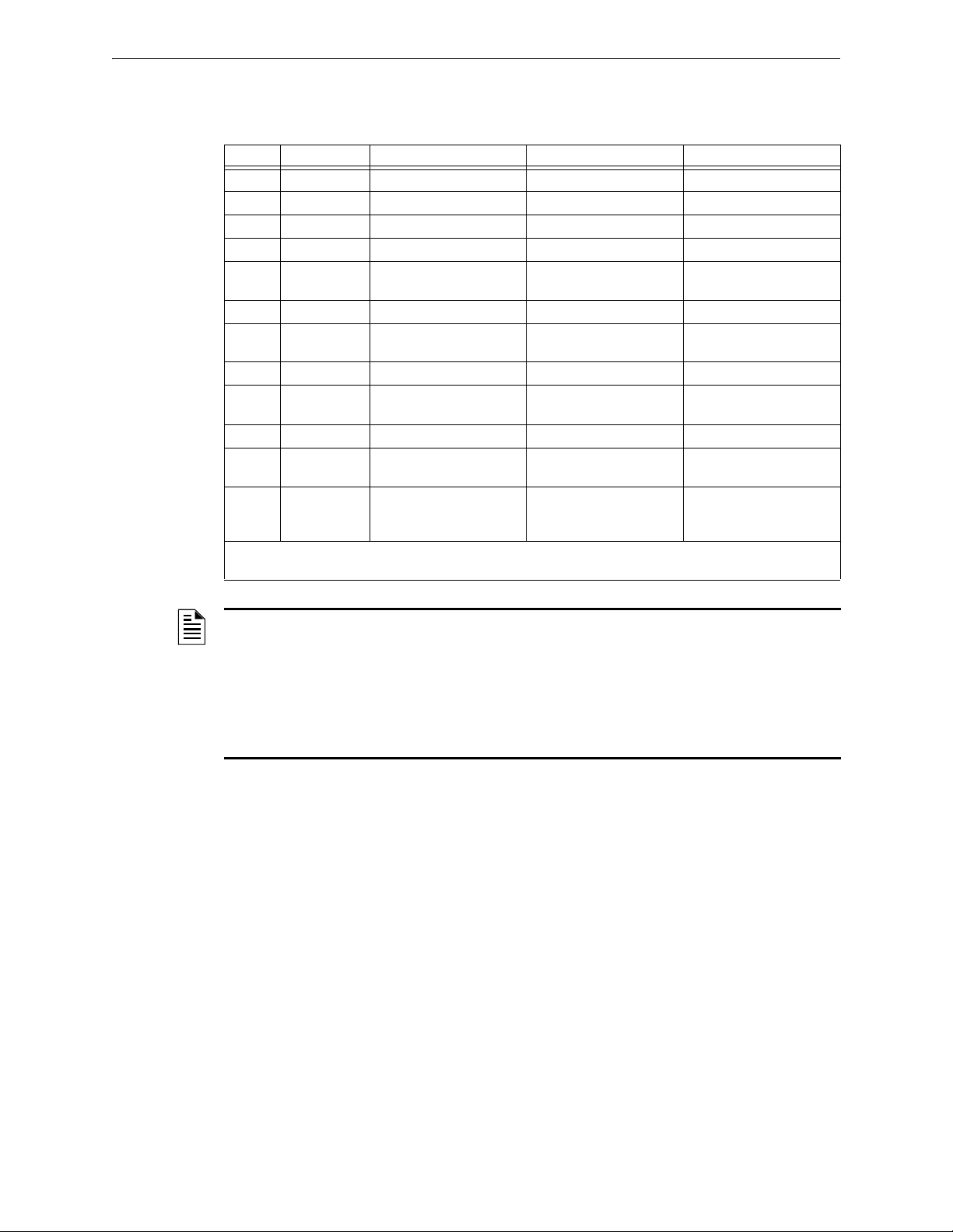
Programming Basic Program
ACS Selection Group P (SLC #1, Modules 65-100 and Detectors 1-14):
Table 2.27 ACS Group P (see note 3)
Point Type Red LED Yellow LED Switch Function*
1 Input SLC 1, Module 65 Alarm SLC 1, Module 65 Trouble Not Used
2 Input SLC 1, Module 66 Alarm SLC 1, Module 66 Trouble Not Used
3 Input SLC 1, Module 67 Alarm SLC 1, Module 67 Trouble Not Used
to to (see note 1) to (see note 1)
36 Input SLC 1, Module 100 Alarm SLC 1, Module 100
Trouble
37 Input SLC 1, Detector 1 Alarm SLC 1, Detector 1 Trouble Not Used
38 Input SLC 1, Detector 1 Trouble
Maintenance Urgent
39 Input SLC 1, Detector 2 Alarm SLC 1, Detector 2 Trouble Not Used
40 Input SLC 1, Detector 2 Trouble
Maintenance Urgent
to (see note 2) to (see note 2)
63 Input SLC 1, Detector 14 Alarm SLC 1, Detector 14
64 Input SLC 1, Detector 14
Trouble Maintenance
Urgent
* Pressing the switch button when the Switch Function is “Not Used” will cause the associated LED to stop
blinking. This is a local acknowledgement at the annunciator only: no message is sent to the panel.
SLC 1, Detector 1 Trouble
Maintenance Alert
SLC 1, Detector 2 Trouble
Maintenance Alert
Trouble
SLC 1, Detector 14
Trouble Maintenance Alert
Not Used
Not Used
Not Used
Not Used
Not Used
NOTE:
1. Point number to Module number relationship is sequential. To determine Point to Module
relationship add 64 to Point number to arrive at Module number.
2. Point number to Detector number relationship is sequential in groups of 2. Since each detector
occupies 2 points, to determine the Point to Detector relationship, count by 2 starting from point
37.
3. This group is only available when UDACT setting is programmed as option 2 and will
automatically be assigned to ACS address 24.
42 NFS2-640/E Programming Manual — P/N 52742:L2 7/17/14
Page 43

Basic Program Programming
ACS Selection Group Q (SLC #2, Modules 65-100 and Detectors 1-14):
Table 2.28 ACS Group Q (see note 3)
Point Type Red LED Yellow LED Switch Function*
1 Input SLC 2, Module 65 Alarm SLC 2, Module 65 Trouble Not Used
2 Input SLC 2, Module 66 Alarm SLC 2, Module 66 Trouble Not Used
3 Input SLC 2, Module 67 Alarm SLC 2, Module 67 Trouble Not Used
to to (see note 1) to (see note 1)
36 Input SLC 2, Module 100 Alarm SLC 2, Module 100
Trouble
37 Input SLC 2, Detector 1 Alarm SLC 2, Detector 1 Trouble Not Used
38 Input SLC 2, Detector 1 Trouble
Maintenance Urgent
39 Input SLC 2, Detector 2 Alarm SLC 2, Detector 2 Trouble Not Used
40 Input SLC 2, Detector 2 Trouble
Maintenance Urgent
to (see note 2) to (see note 2)
63 Input SLC 2, Detector 14 Alarm SLC 2, Detector 14
64 Input SLC 2, Detector 14
Trouble Maintenance
Urgent
* Pressing the switch button when the Switch Function is “Not Used” will cause the associated LED to stop
blinking. This is a local acknowledgement at the annunciator only: no message is sent to the panel.
SLC 2, Detector 1 Trouble
Maintenance Alert
SLC 2, Detector 2 Trouble
Maintenance Alert
Trouble
SLC 2, Detector 14
Trouble Maintenance Alert
Not Used
Not Used
Not Used
Not Used
Not Used
NOTE:
1. Point number to Module number relationship is sequential. To determine Point to Module
relationship add 64 to Point number to arrive at Module number.
2. Point number to Detector number relationship is sequential in groups of 2. Since each detector
occupies 2 points, to determine the Point to Detector relationship, count by 2 starting from point
37.
3. This group is only available when UDACT setting is programmed as option 2 and will
automatically be assigned to ACS address 25.
NFS2-640/E Programming Manual — P/N 52742:L2 7/17/14 43
Page 44

Programming Basic Program
ACS Selection Group R (SLC #1, Detectors 15-46):
Table 2.29 ACS Group R
Point Type Red LED Yellow LED Switch Function*
1 Input Detector 015 Alarm Detector 015 Trouble Not Used
2 Input Detector 015 Trouble
Maintenance Urgent
3 Input Detector 016 Alarm Detector 016 Trouble Not Used
4 Input Detector 016 Trouble
Maintenance Urgent
to to (see note 1) to (see note 1)
63 Input Detector 046 Alarm Detector 046 Trouble Not Used
64 Input Detector 046 trouble
Maintenance Urgent
* Pressing the switch button when the Switch Function is “Not Used” will cause the associated LED to
stop blinking. This is a local acknowledgement at the annunciator only: no message is sent to the panel.
NOTE:
1.Point number to Detector number relationship is sequential in groups of 2. Since each detector
occupies 2 points, to determine the Point to Detector relationship, start with detector 15 and count
by 2 starting from point 1.
2. This group is only available when UDACT setting is programmed as option 2 and will
automatically be assigned to ACS address 26.
Detector 015 Trouble
Maintenance Alert
Detector 016 Trouble
Maintenance Alert
Detector 046 Trouble
Maintenance Alert
Not Used
Not Used
Not Used
ACS Selection Group S (SLC #2, Detectors 15-46):
Table 2.30 ACS Group S
Point Type Red LED Yellow LED Switch Function*
1 Input Detector 015 Alarm Detector 015 Trouble Not Used
2 Input Detector 015 Trouble
Maintenance Urgent
3 Input Detector 016 Alarm Detector 016 Trouble Not Used
4 Input Detector 016 Trouble
Maintenance Urgent
to to (see note 1) to (see note 1)
63 Input Detector 046 Alarm Detector 046 Trouble Not Used
64 Input Detector 046 Trouble
Maintenance Urgent
* Pressing the switch button when the Switch Function is “Not Used” will cause the associated LED to
stop blinking. This is a local acknowledgement at the annunciator only: no message is sent to the panel.
NOTE:
1. Point number to Detector number relationship is sequential in groups of 2. Since each detector
occupies 2 points, to determine the Point to Detector relationship, start with detector 15 and count
by 2 starting from point 1.
2. This group is only available when UDACT setting is programmed as option 2 and will
automatically be assigned to ACS address 27.
Detector 015 Trouble
Maintenance Alert
Detector 016 Trouble
Maintenance Alert
Detector 046 Trouble
Maintenance Alert
Not Used
Not Used
Not Used
44 NFS2-640/E Programming Manual — P/N 52742:L2 7/17/14
Page 45

Basic Program Programming
ACS Selection Group T (SLC #1, Detectors 47-78):
Table 2.31 ACS Group T
Point Type Red LED Yellow LED Switch Function*
1 Input Detector 047 Alarm Detector 047 Trouble Not Used
2 Input Detector 047 trouble
Maintenance Urgent
3 Input Detector 048 Alarm Detector 048 Trouble Not Used
4 Input Detector 048 Trouble
Maintenance Urgent
to to (see note 1) to (see note 1)
63 Input Detector 078 Alarm Detector 078 Trouble Not Used
64 Input Detector 078 Trouble
Maintenance Urgent
* Pressing the switch button when the Switch Function is “Not Used” will cause the associated LED to
stop blinking. This is a local acknowledgement at the annunciator only: no message is sent to the panel.
NOTE:
1. Point number to Detector number relationship is sequential in groups of 2. Since each detector
occupies 2 points, to determine the Point to Detector relationship, start with detector 47 and count
by 2 starting from point 1.
2. This group is only available when UDACT setting is programmed as option 2 and will
automatically be assigned to ACS address 28.
Detector 047 Trouble
Maintenance Alert
Detector 048 Trouble
Maintenance Alert
Detector 078 Trouble
Maintenance Alert
Not Used
Not Used
Not Used
ACS Selection Group U (SLC #2, Detectors 47-78):
Table 2.32 ACS Group U
Point Type Red LED Yellow LED Switch Function*
1 Input Detector 047 Alarm Detector 047 Trouble Not Used
2 Input Detector 047 Trouble
Maintenance Urgent
3 Input Detector 048 Alarm Detector 048 Trouble Not Used
4 Input Detector 048 Trouble
Maintenance Urgent
to to (see note 1) to (see note 1)
63 Input Detector 078 Alarm Detector 078 Trouble Not Used
64 Input Detector 078 Trouble
Maintenance Urgent
* Pressing the switch button when the Switch Function is “Not Used” will cause the associated LED to
stop blinking. This is a local acknowledgement at the annunciator only: no message is sent to the panel.
NOTE:
1. Point number to Detector number relationship is sequential in groups of 2. Since each detector
occupies 2 points, to determine the Point to Detector relationship, start with detector 47 and count
by 2 starting from point 1.
2. This group is only available when UDACT setting is programmed as option 2 and will
automatically be assigned to ACS address 29.
Detector 047 Trouble
Maintenance Alert
Detector 048 Trouble
Maintenance Alert
Detector 078 Trouble
Maintenance Alert
Not Used
Not Used
Not Used
NFS2-640/E Programming Manual — P/N 52742:L2 7/17/14 45
Page 46

Programming Basic Program
ACS Selection Group V (SLC #1, Detectors 79-100):
Table 2.33 ACS Group V
Point Type Red LED Yellow LED Switch Function*
1 Input Detector 079 Alarm Detector 079 Trouble Not Used
2 Input Detector 079 Trouble
Maintenance Urgent
3 Input Detector 080 Alarm Detector 080 Trouble Not Used
4 Input Detector 080 Trouble
Maintenance Urgent
to to (see note 1) to (see note 1)
63 Input Detector 100 Alarm Detector 100 Trouble Not Used
64 Input Detector 100 Trouble
Maintenance Urgent
* Pressing the switch button when the Switch Function is “Not Used” will cause the associated LED to
stop blinking. This is a local acknowledgement at the annunciator only: no message is sent to the panel.
NOTE:
1. Point number to Detector number relationship is sequential in groups of 2. Since each detector
occupies 2 points, to determine the Point to Detector relationship, start with detector 79 and count
by 2 starting from point 1.
2. This group is only available when UDACT setting is programmed as option 2 and will
automatically be assigned to ACS address 30.
Detector 079 Trouble
Maintenance Alert
Detector 080 Trouble
Maintenance Alert
Detector 100 Trouble
Maintenance Alert
Not Used
Not Used
Not Used
ACS Selection Group W (SLC #2, Detectors 79-100):
Table 2.34 ACS Group W
Point Type Red LED Yellow LED Switch Function*
1 Input Detector 079 Alarm Detector 079 Trouble Not Used
2 Input Detector 079 Trouble
Maintenance Urgent
3 Input Detector 080 Alarm Detector 080 Trouble Not Used
4 Input Detector 080 Trouble
Maintenance Urgent
to to (see note 1) to (see note 1)
63 Input Detector 100 Alarm Detector 100 Trouble Not Used
64 Input Detector 100 Trouble
Maintenance Urgent
* Pressing the switch button when the Switch Function is “Not Used” will cause the associated LED to
stop blinking. This is a local acknowledgement at the annunciator only: no message is sent to the panel.
NOTE:
1. Point number to Detector number relationship is sequential in groups of 2. Since each detector
occupies 2 points, to determine the Point to Detector relationship, start with detector 79 and count
by 2 starting from point 1.
2. This group is only available when UDACT setting is programmed as option 2 and will
automatically be assigned to ACS address 31.
Detector 079 Trouble
Maintenance Alert
Detector 080 Trouble
Maintenance Alert
Detector 100 Trouble
Maintenance Alert
Not Used
Not Used
Not Used
46 NFS2-640/E Programming Manual — P/N 52742:L2 7/17/14
Page 47

The Network Program Programming
Program Change
Password
PROGRAM CHECK OK.
RE-TEST PANEL NOW 08:34A 041508 Tue
Program Change
Password
THRESHOLD CH.A:H, THRESHOLD CH.B:H,
NODE: .000, STYLE7:N, <ENTER>
2.3.9 How to Check the Program for Errors (8=CHECK PRG)
When finished programming, you can use the Check option to search the
program entries for possible errors. From the “Basic Program” screen, press
the 8 key. The Check option searches the program for the following
conditions that can cause errors:
• Output points mapped to a zone without a mapped input
• A zone with mapped input points without mapped output points (including Z00 outputs)
• Releasing zone inputs (R0-R9) with no
CKT outputs with no R0-R9 inputs mapped to them
• RO-R9 inputs not mapped to
MAN. RELEASE.
For more information on Releasing Zones, refer to “Releasing Applications” on page 60.
RELEASE CKT outputs mapped to them; or RELEASE
If the Check option detects multiple devices that fail the check, press the
step through the devices. If the Check option displays errors, return to Point Programming
(“Modify or Delete a Point (2=point)” on page 19) and correct the errors. The figure below shows a
sample display of program screen that appears after a successful program check:
2.4 The Network Program
From the “Program Change Selection” screen, press the 2 key to display the
“Network” screen, which displays as follows:
THRESHOLD CH.A: - Enter H or L, for high or low threshold setting for channel A on the NCM
module.
THRESHOLD CH.B: - Enter H or L, for high or low threshold setting for channel B on the NCM
module.
NODE: - Enter the panel’s network node number. The valid network node number range is 1-103.
The number will be entered after the decimal point; the spaces before the decimal point are for
future use.
PREVIOUS or NEXT key to
STYLE7: - Enter N for network style determination (either Style 4 or Style 7) through
autoprogramming. Enter Y to force a Style 7 designation for network wiring.
NOTE: If network Style 7 wiring is determined by autoprogramming, a change in the wiring (for
example, a break in the network wiring) would cause the system to reassess the network wiring
style as 4. If network Style 7 wiring is forced, a break in the wiring will create a trouble message.
NFS2-640/E Programming Manual — P/N 52742:L2 7/17/14 47
Page 48
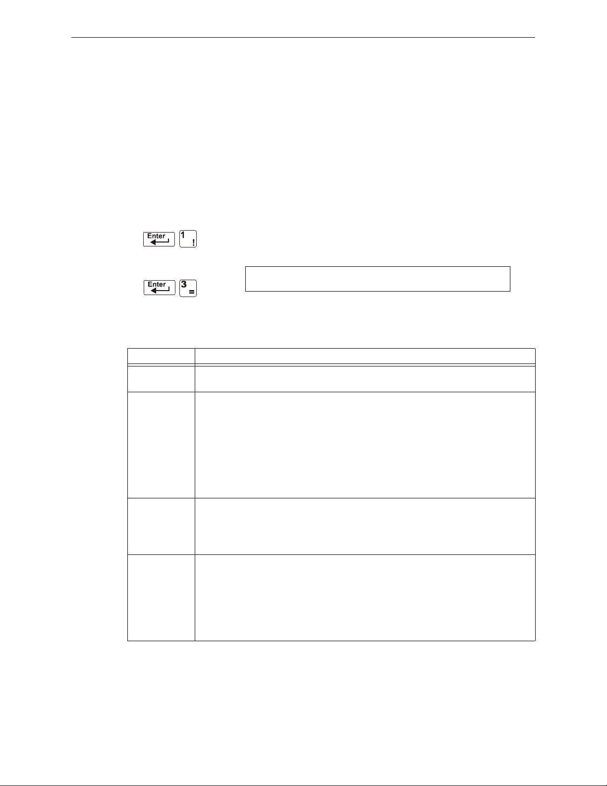
Programming The Utility Program
Program Change
Password
REGION=0 TBL.REMIND=2 ALA.SCROLL=N
LOCAL CONTROL=0 IP-ACCESS=0 DCC-mode:Y
To select network options, follow these steps:
1. Using the arrow keys, move the blinking cursor to a selection.
2. Press the
NEXT or PREVIOUS key to select H or L (Threshold Ch. A, Threshold Ch. B). a three-
digit number (Node), or Y or N (Style 7).
When finished making selections, press the
normal operation.
When programming is complete, the panel must be reset to register the programming.
2.5 The Utility Program
There are five options available in the Utility Program. Enter the program and select an option as
described below.
From the “Program Change Selection” screen, press the 3 key to display the
“Utility Program” screen as shown below:
Descriptions of the five options on the Utility Program screen:
Table 2.35 Utility Program Options (1 of 2)
Utility Option Description
REGION 0 = No special region setting (default)
TBL.REMIND
TBL Reminder*
*
Use of a setting other
than “2” requires AHJ
approval.
ALA.SCROLL
Alarm Scroll*
*
Setting this field to “Y”
requires AHJ approval.
LOCAL
CONTROL
1 = China
This option provides trouble resound selections to meet the requirements of NFPA 72-2002,
which you can select as follows:
• Select * if you don’t want a trouble reminder
• Select 1 to sound a short trouble reminder tone every minute
• Select 2 to resound a trouble tone every 24 hours at 11:00 AM, and to send a reminder every
sixty seconds for acknowledged events.
• Select 3 to display a detector while in the alarm verification mode and no trouble reminder
• Select 4 for once a minute trouble reminder with alarm verification display
• Select 5 for trouble reminder resound every 24 hours at 11:00 AM with alarm verification
display, and to send a reminder every sixty seconds for acknowledged troubles
This option allows the programmer to select how alarms are displayed.
• Select Y if you want each alarm displayed for approximately two seconds, and to
acknowledge all alarms with a single acknowledgement. (default)
• Select N if you want only the first alarm and the alarm count displayed, and to acknowledge
each alarm singly, point by point.
This option allows the programmer to disable local control of the
key,
SIGNAL SILENCE key, DRILL key and SYSTEM RESET key. Select local control as follows:
• Select 0 to disable local control
• Select 1 to enable local control (default)
• Select 2 to enable partial local control. This setting allows control of the
SYSTEM RESET keys only (required in Chicago.)
Note that if the panel is to be controlled exclusively by a Display and Control Center (DCC),
Local Control should be disabled.
ESC key three times to return the control panel to
ACKNOWLEDGE/SCROLL DISPLAY
ACKNOWLEDGE and
48 NFS2-640/E Programming Manual — P/N 52742:L2 7/17/14
Page 49

FlashScan Poll Programming
Program Change
Password
FLASHSCAN L1DET L1MOD L2DET L2MOD
N NNN
Table 2.35 Utility Program Options (2 of 2)
Utility Option Description
IP ACCESS Note: Use of this option is subject to local AHJ approval.
This option allows the programmer to choose one of three options for Wide Area Network
(WAN) communication. Acceptance of commands, downloads and programming from over the
WAN can be enabled, disabled or timed.
Select IP ACCESS as follows:
• Select 0 to disable IP access
• Select 1 to enable IP access
• Select 2 to enable IP access for two hours.
Note that enabling IP ACCESS allows downloads over a local area network (LAN) or the
internet (Wide Area Network - WAN) using VeriFire Tools through a Noti•Fire•Net(NFN) Web
Server (NWS), or a wide-area enabled NCS through a PC version of NFN Gateway. Always
verify system operation after programming changes are made in this manner.
DCC Mode This option allows the programmer to select whether this panel will participate in DCC (Display
and Control Center) functions. Select Y for participation, N for no participation.
NOTE: For Mass Notification applications, DCC participation should be disabled.
To select utility options, follow these steps:
1. Using the arrow keys, move the blinking cursor to a selection.
2. Press the
NEXT or PREVIOUS key to select
- Local Control
- *, 1, 2, 3, 4, 5 (TBL Reminder)
- 0, 1, or 2 (IP ACCESS)
- DCC Mode
3. When finished making selections, press the
normal operation.
2.6 FlashScan Poll
ESC key three times to return the control panel to
From the “Program Change Selection” screen, press the 4 key to access the
“FlashScan Poll” selection screen as shown below:
This menu allows the selection of CLIP (Classic Loop Interface Protocol) or FlashScan detectors
and modules for each loop. Once this screen is accessed, the cursor will be positioned underneath
the Loop #1 Detector selection, blinking the currently selected protocol type. The default selections
are shown in the above figure. This indicates that both Loop #1 and Loop #2 detectors and modules
are selected to use CLIP devices. If FlashScan devices are to be employed, change the blinking
cursor by pressing the Y key or toggle it by using the
have been made to the detectors and modules of both loops, press the
panel will reset.
Most FlashScan devices can be programmed to run in either CLIP or FlashScan mode. Observe one
of the following three options when using FlashScan devices:
Option 1 Program all modules and detectors on an SLC as FlashScan.
(In the “FlashScan Poll” screen, enter Y for DET and Y for MOD. It is possible to
have up to 159 FlashScan modules and 159 FlashScan detectors on this SLC.)
NFS2-640/E Programming Manual — P/N 52742:L2 7/17/14 49
PREVIOUS or NEXT key. After the selections
ENTER key, at which time the
Page 50
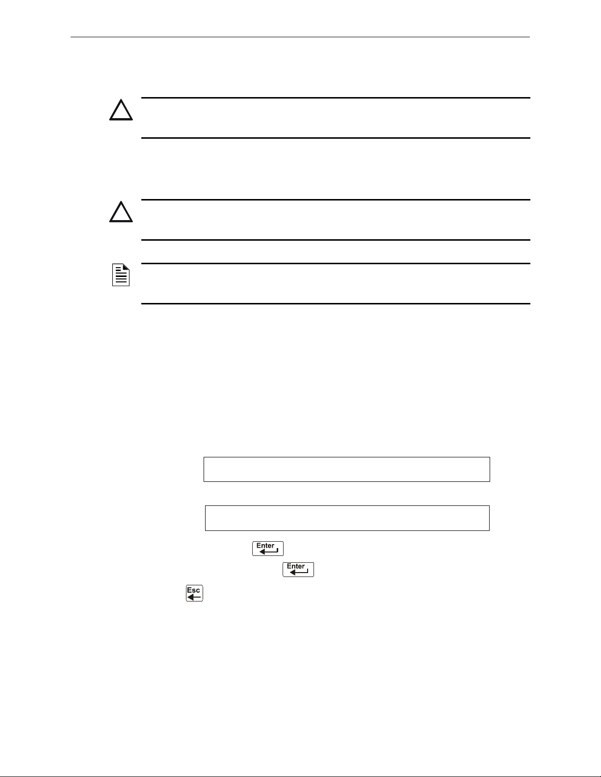
Programming Setting the Baud Rate of Serial Ports
!
!
1=PROGRAMMING 2=READ STATUS ENTRY
(ESCAPE TO ABORT)
ENTER PROG OR STAT PASSWORD, THEN ENTER.
_ (ESCAPE TO ABORT)
Option 2 Program all modules and detectors on an SLC as CLIP.
(In the “FlashScan Poll” screen, enter N for DET and N for MOD. It is possible to
have up to 99 CLIP modules and 99 CLIP detectors on this SLC.)
CAUTION:
Do not program more than 99 CLIP addresses, as this will compromise the response time of the
panel to display off-normal events.
Option 3 Program all detectors as CLIP and all modules as FlashScan on an SLC.
(In the “FlashScan Poll” screen, enter N for DET and Y for MOD. It is possible to
have up to 99 CLIP detectors and 159 FlashScan modules on this SLC.)
CAUTION:
Do not program modules as CLIP and detectors as FlashScan on the same SLC. This combination
is not an option: Y for DET, N for MOD in the “FlashScan Poll” screen.
NOTE: Autoprogramming following a Clear Program command will cause the panel to determine
the FlashScan capability of each loop based on whether all devices on a loop are FlashScan or
not. It will set the loop settings to FlashScan if necessary.
Refer to the SLC manual for available devices.
2.7 Setting the Baud Rate of Serial Ports
2.7.1 Printer Serial Port
The default baud rate of the EIA-232 Printer connection (serial printer port) is 9600. To change
baud rate to 2400 or 4800, follow these steps:
1. From the “SYSTEM NORMAL” screen, press the
screen, as shown below:
2. Press the 1 key. The control panel displays the Enter Password screen, as shown below:
3. Enter 2400B and press
will disappear when you press
4. Press
twice to return to the “SYSTEM NORMAL” screen.
. The five asterisks that appear when you type in the baud rate
.
ENTER key to display the Program Entry
5. To switch from 2400 baud to 4800 or 9600 baud repeat steps 1, 2, and 3 entering 9600B or
4800B.
50 NFS2-640/E Programming Manual — P/N 52742:L2 7/17/14
Page 51

Setting the Baud Rate of Serial Ports Programming
1=PROGRAMMING 2=READ STATUS ENTRY
(ESCAPE TO ABORT)
ENTER PROG OR STAT PASSWORD, THEN ENTER.
_ (ESCAPE TO ABORT)
2.7.2 CRT Serial Port
The default setting for the serial EIA-232 CRT port is “disabled”. To enable the EIA-232 CRT port
at 9600 baud, follow the steps below.
NOTE: The serial EIA-232 CRT port can only be enabled in standalone (non-networked)
applications. The only baud rate supported is 9600.
1. From the SYSTEM NORMAL screen, press the
ENTER key to display the Program Entry
screen, as shown below:
2. Press the 1 key. The control panel displays the Enter Password screen, as shown below:
3. Enter CRT96 and press
will disappear when you press
4. Press
twice to return to the “SYSTEM NORMAL” screen.
. The five asterisks that appear when you type in the code
.
5. To switch back to the default network mode (no CRT) repeat steps 1, 2, and 3 entering
NOCRT.
NFS2-640/E Programming Manual — P/N 52742:L2 7/17/14 51
Page 52

3.1 Overview
1=PROGRAMMING 2=READ STATUS ENTRY
ENTER PROG OR STAT PASSWORD, THEN ENTER.
STATUS CHANGE PRESS: 1=DISABL 2=SENSITIV
3=CLR VER 4=CLR HIST 5=TIME 6=WALK TEST
Status Change provides a second programming level - accessed by an assigned password - for
changing operating parameters. (These operating parameters do not affect control program
settings.) For example, the Status Change password lets you change settings such as detector
sensitivity and system time and date.
NOTE: Assign the Status Change password to persons who do not have access to Level 1
programming options.
Status Change Options are described below.
Option 1=DISABL - The Disable/Enable option lets you disable programmed points for detectors,
modules, zones and NACs. For details, refer to “Disable or Enable a Point” on page 53.
Option 2=SENSITIV - The Detector Sensitivity option lets you change the Alarm and Pre-alarm
(sensitivity) level for an installed detector. For details, refer to “Changing Detector Sensitivity” on
page 54.
Option 3=CLR VER - The Clear Verification screen lets you clear all counters for detectors
selected for Alarm Verification. For details, refer to “Clearing Alarm Verification Counters” on
page 55.
Section 3: Status Change
Option 4=CLR HIST - The Clear History screen lets you clear the entire History buffer from
memory. For details, refer to “Clearing the History Buffer” on page 55.
Option 5=TIME - The Time/Date option lets you set the time and date for the system clock. For
details, refer to “Setting the System Time and Date” on page 55.
Option 6=WALK TEST - The Walk Test option lets you test the entire fire alarm system while
away from the control panel. For details, refer to “Walk Test” on page 56”.
3.2 How to Enter Status Change
To enter Status Change, follow these steps:
1. From the SYSTEM NORMAL” screen, press the
“Entry” screen, as shown below:
2. From the “Entry” screen, press the 1 key. The control panel displays the “Enter Password”
screen as shown below:
3. Enter your Status Change password (See “How to Enter a Password”, page page 11). The
control panel displays the “Status Change Selection” screen, as shown below:
ENTER key. The control panel displays the
4. Select a Status Change selection: 1,2,3,4,5, or 6.
52 NFS2-640/E Programming Manual — P/N 52742:L2 7/17/14
Page 53

Disable or Enable a Point Status Change
!
Status Change
Password
!
ENABLE CONTROL CONTROL ADDRESS 2M101
00 __ __ __ __ ISW 2M101
Blinking status banner (ENABLE or DISABL)
3.3 Disable or Enable a Point
WARNING:
Do not rely on disable/enable software settings to lock out releasing devices. Releasing devices
must be physically disconnected.
NOTE: When an input or output point associated with releasing functions is disabled, a single
supervisory trouble will be generated.
The Disable/Enable option lets you disable programmed points for detectors,
modules, zones, and NACs. The program allows you to disable an initiating
device in alarm: however, the disable will not take effect until after the panel
has been reset.
1. From the “Status Change Selection” screen, press the 1 key to display the “Disable/Enable”
screen.
2. Select the point type:
for detectors
for modules
for NACs
for zones
The cursor will blink the first SLC address digit in the detector, zone, module, or NAC field.
D
WARNING:
Disabling a zone disables all input and output devices that use the zone as the first entry in the
CBE list.
3. Enter the address of the point, then press the
When you disable a point and press the
panel: a) turns on the
banner to
TROUBL for the point.
POINT DISABLED LED; b) sounds the panel sounder; and c) changes the status
ESC key to return to the Disable/Enable screen, the control
ENTER key. A sample display follows:
You can disable or enable a point by changing the status banner as follows:
Table 3.1 Changing the Status Banner (1 of 2)
To Pr ess
Change the status Maneuver the cursor with the arrow keys until it is in the status field. Press
(Next Selection) or (Previous Selection)
NFS2-640/E Programming Manual — P/N 52742:L2 7/17/14 53
Page 54

Status Change Changing Detector Sensitivity
Status C
Passwo
DET. SENS. & COMP. ENTER POINTS:LDAAA,E
Pre-Alarm Level
Alarm Level
PROGRM SMOKE(PHOTO) DETECTOR ADDR 2D101
03 __ __ __ __A8P8AV 2D101
Table 3.1 Changing the Status Banner (2 of 2)
To Pr ess
Save the status
Go to the next or previous
point address
(Next Selection) or (Previous Selection)
3.4 Changing Detector Sensitivity
The Detector Sensitivity option lets you change the Alarm and Pre-Alarm
(sensitivity) level for an installed detector. From the “Status Change Selection”
screen, press the 2 key to display the “Detector Selection” screen as shown
below:
To select a detector, enter the SLC address (2D101) of an installed detector in the “LDAAA” field
(shown above). The control panel displays the following screen:
Use the instructions below to set/change detector sensitivity, display additional detectors, and set
Pre-alarm values.
NOTE: If not using Pre-Alarm, set PA=0. PA=1 is the self-optimizing mode. For details, refer to
“Pre-Alarm” on page 99.
To Enter or Press
Display detector information on
the screen.
Set alarm sensitivity level.
Set Pre-alarm level
The detector address, then press .
A value (1-9) or increase or decrease values by pressing
NEXT or PREVIOUS keys: or .
the
A value (0-9) or increase or decrease values by pressing
Save the sensitivity values.
Display the next existing
detector address.
Display the previous existing
detector address.
54 NFS2-640/E Programming Manual — P/N 52742:L2 7/17/14
NEXT or PREVIOUS keys: or .
the
(Next Selection)
(Previous Selection)
Page 55
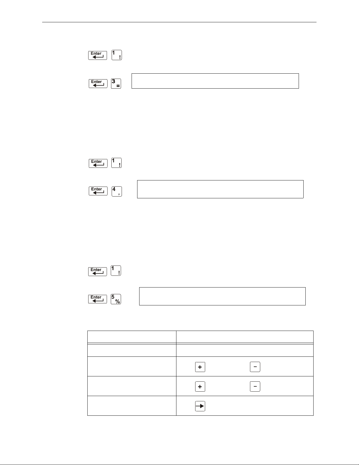
Clearing Alarm Verification Counters Status Change
Status Change
Password
PRESS ENTER TO CLEAR VERIFICATION COUNTS
OR ESCAPE TO ABORT
Status Change
Password
PRESS ENTER TO CLEAR HISTORY FILE
OR ESCAPE TO ABORT
Status Change
Password
CHANGE TIME/DATE
11:40A Tue 04/15/2008
3.5 Clearing Alarm Verification Counters
The Clear Verification screen lets you clear all counters for detectors selected
for Alarm Verification. From the “Status Change Selection” screen, press the 3
key to display the “Clear Verification” screen as shown below:
From the Clear Verification screen, you can do the following:
• Press the
ENTER key to clear all verification counters and return to the “Status Change
Selection” screen; or
• Press the
ESC key to return to the “Status Change Selection” screen without clearing.
3.6 Clearing the History Buffer
The Clear History screen lets you clear the entire History buffer from memory.
Press the 4 key from the “Status Change Selection” screen to display the “Clear
History” screen as shown below:
From the Clear History screen, you can do the following:
• Press the
ENTER key to clear the contents of the History buffer and return to the “Status
Change Selection” screen; or
• Press the
ESC key to return to the “Status Change Selection” screen without clearing.
3.7 Setting the System Time and Date
The Time/Date option lets you set the time and date for the system clock. Press
the 5 key from the “Status Change Selection” screen to display the “Time/Date”
screen as shown below:
The first digit flashes until you change the value or press the
date, follow the instructions below:
To Do this
Change the time and date values Enter values from the numeric keys on the keypad.
Change A (AM) or P (PM)
Change the day
Move to another digit
NFS2-640/E Programming Manual — P/N 52742:L2 7/17/14 55
ENTER key. To set the system time and
Press (Next Selection) or (Previous Selection)
Press (Next Selection) or (Previous Selection)
Press
Page 56

Status Change Walk Test
!
!
To Do this
Save the time and date and return
Press
3.8 Walk Test
Walk Test allows the user to test the entire fire alarm system. There are two kinds of Walk Test Basic and Advanced, described later in this section.
Before entering Walk Test, note the following:
• For each individual activation, the control panel sends “TEST Axx” (for alarm testing) or
TEST Txx (for trouble testing) to the History buffer, installed printers and CRT-2s so results
can be reviewed.
• Basic Walk Test, Silent – In order to keep the test silent, do not program any of the output
modules with “W” in the Walk Test field.
• Advanced Walk Test - This test overrides a setting of “
activated outputs will sound until panel reset.
• The control panel provides a 1-hour timer for Walk Test mode. When the hour expires with
no activity, the control panel automatically returns to normal operation.
• Walk Test may be exited at any time by pressing the ESC key.
*” (silent) in the Walk Test field. All
WARNING:
Walk Test mode deactivates fire protection. Always observe the following:
1. Prior to Walk Test, secure all protected buildings, and notify the building owner/operator,
fire department, and other pertinent personnel that testing is in progress.
2. Immediately after Walk Test is completed, notify the same people that testing is complete
and is restored to normal operation.
WARNING:
Physically disconnect all releasing devices before starting Walk Test. It is not sufficient to
disable in any other manner.
NOTE: Walk Test will not start if any devices are active (i.e., fire alarms, security, supervisories
or pre-alarms.) To perform a walk test while a device is active, disable the device and press the
System Reset button.
For information on programming Walk Test field selections, refer to “Modify an Addressable
Monitor Module Point” on page 22 or “Modify NAC Points” on page 24.
56 NFS2-640/E Programming Manual — P/N 52742:L2 7/17/14
Page 57

Walk Test Status Change
Status Change
Password
WALK TEST PRESS ENTER TO START
ESCAPE TO ABORT
3.8.1 Basic Walk Test
When the tester activates an input during Basic Walk Test, all silenceable outputs mapped by CBE
to that input will activate. The activations are tracking; once the activation stimulus is removed, the
input will deactivate. Basic Walk Test may be audible or silent, depending on the Walk Test setting
of participating outputs. Program the Walk Test field for control modules and NACs as follows:
For
an audible Basic Walk Test W sound for approximately 4 seconds
a silent Basic Walk Test
a trouble Basic Walk Test W sound for approximately 8 seconds
Program Silenceable
Outputs with
* not sound during Walk Test
Silenceable Outputs will
during Walk Test
when put into trouble
Enter Basic Walk Test in the following manner:
From the “Status Change Selection” screen, press the 6 key. The control panel
displays the “Walk Test” screen as shown below:
Operate the control panel in Walk Test as follows
To P re ss
Put the control panel into Walk Test mode
Stop a Walk Test and return to the “Status Change Selection” screen
Basic Walk Test directs the control panel to do the following:
• Activate silenceable outputs associated by programming with each new alarm. (The panel
does not activate non-silenceable outputs.)
• Save and store each test in the History buffer
• Send a TEST Axx status banner for each alarm, and a TEST TXX banner for each trouble,
to the printer (xx equals the number of tests for a detector or input device with this address)
• Turn on the System Trouble LED
• Turn on the System Trouble relay
• Disable activation of the System Alarm relay
NFS2-640/E Programming Manual — P/N 52742:L2 7/17/14 57
Page 58
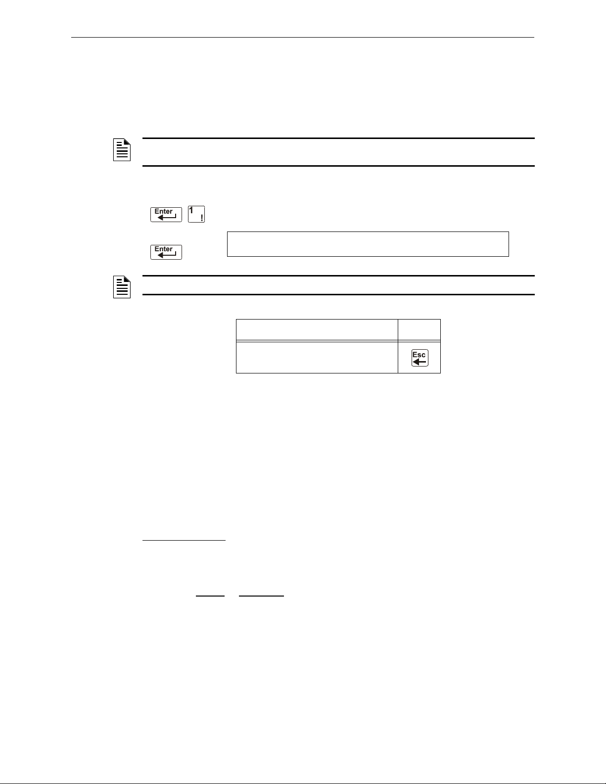
Status Change Walk Test
LTE ST
TROUBL IN SYSTEM ADV WALK TEST
PROCESSING DISABLED 10:07a 041508 MON
3.8.2 Advanced Walk Test
During Advanced Walk Test, when the tester activates an input, all CBE mapped to that input will
activate with the exception of releasing functions. Each input activation is latching; that is, it will
not deactivate until the system is reset. Advanced Walk Test will sound all activated outputs,
overriding a setting of “
NOTE: Some detectors, laser detectors for example, can be difficult to place in alarm using a magnet.
Advanced Walk Test facilitates magnet testing of these detectors.
Enter Advanced Walk Test as follows:
NOTE: The control panel can not be put into Walk Test from an alarm condition.
*” (silent) in the Walk Test field.
Enter LTEST at the password screen. Asterisks will display where LTEST has
been typed. Pressing
ENTER displays the following screen.
To Pr ess
Stop an Advanced Walk Test and return to
the “Status Change Selection” screen
Advanced Walk Test directs the control panel to do the same as it does for Basic Walk Test (see
“3.8.1, "Basic Walk Test"” above) with the following exceptions:
• alarm and trouble messages are sent to the printer, not test messages. (These Walk Test
messages can be distinguished from others at the printer because they begin with the trouble
message generated when Walk Test is entered, and end with the cleared trouble when Walk
Test is exited.)
• all CBE mapped to the test input is activated except releasing functions.
3.8.3 Walk Test Activation Indications
Walk Test Activation Indications
FlashScan poll mode
• each intelligent addressable input device will blink its address in red, and each intelligent
addressable output device will blink its address in green. Pattern examples are given below.
Address Blink Pattern
- Once the test is started:
8 8 blinks, long stop, 8 blinks, long stop,....
37 3 blinks, stop, 7 blinks, long stop, 3 blinks, stop, 7 blinks, long stop,....
70 7 blinks, stop, 10 blinks, long stop, 7 blinks, stop,.....
107 10 blinks, stop, 7 blinks, long stop, 10 blinks, stop,.....
152 15 blinks, stop, 2 blinks, long stop, 15 blinks, stop, 2 blinks, long
58 NFS2-640/E Programming Manual — P/N 52742:L2 7/17/14
stop....
Page 59

Walk Test Status Change
• an input device activated in Basic Walk Test latches on steady green for the duration of the
test.
• an output device activated in Basic Walk Test will remain active and the LED will glow
steady green for:
- approximately 4 seconds for alarms
- approximately 8 seconds for troubles.
• an output device activated in Advanced Walk Test will remain active and the LED will
glow steady green until the reset key is pressed.
CLIP mode
- Once the test is started:
• intelligent addressable input and output devices continue to blink red as usual until
activated.
• an input device activated in Basic Walk Test latches on steady red during activation. If the
device is put in trouble (for instance, the detector head is removed, then replaced), the LED
will be latched on for the duration of the test.
• an output device activated during Basic Walk Test will remain active and the LED will
glow steady green (if a FlashScan module) or steady red (if a CLIP module) for:
- approximately 4 seconds for alarms
- approximately 8 seconds for troubles.
• an output device activated in Advanced Walk Test will remain active and the LED will
glow steady green (if a FlashScan module) or steady red (if a CLIP module) until the reset
key is pressed.
3.8.4 Viewing Walk Test Results
When finished with a Walk Test, view the History buffer, installed printers and CRT-2s to check the
results of the Walk Test. View the History buffer by using the Read Status function. From the
SYSTEM NORMAL screen, press the
key to view the History buffer. For further instructions on using the Read Status function, refer to
the NF2S-640 Operations Manual.
ENTER key, press the 2 key two times, then press the ENTER
NFS2-640/E Programming Manual — P/N 52742:L2 7/17/14 59
Page 60

Appendix A: Releasing Applications
!
PRG RELEASE FUNCTION RELEASE CONTROL
DELAY=30 ABORT=ULI CROSS=N SOK=0000 R05
WARNING:
When used for CO2 releasing applications, observe proper precautions as stated in NFPA 12. Do not
enter the protected space unless physical lockout and other safety procedures are fully completed.
Do not use software disable functions in the panel as lockout.
Do not enable the BACKUP option switch for any of the four Notification Appliance Circuits (NACs) if
they are used for releasing functions.
A.1 Overview
A.1.1 Description of Releasing Zones
The control panel includes ten Releasing Zones (R0-R9) that can be used to control up to ten
releasing operations. Each zone operates independently, and is fully programmable..
NOTE: Releasing Zones R0-R9 appear in the CBE list of devices as ZR0-ZR9. For example, if
you list R5 for a detector, one of the five zones in the CBE list of the detector will display as ZR05.
From the “Special Function Change” screen (refer to “Program Special Zones (6=spl funct)” on
page 27), select a Releasing Zone (R0-R9) to display the “Releasing Function” screen:
Each Releasing Zone includes four releasing functions, outlined below:
Table A.1 Releasing Zone Functions
Function Lets You
Delay Program a 01 to 60-second Delay Timer (or 00, no delay). The Delay Timer equals the
Abort Select a 3-letter Abort switch Type Code (ULI, IRI, NYC, or AHJ) that adds a delay time to
Cross Select one of three Cross Zone types or “N” (not used). A Cross Zone requires tripping two
Soak Select a Soak Timer (0001-9999 seconds) or “0000” (not used). Refer to “Programming a
time that must elapse between activating an initiating device and activating the releasing
zones mapped to the active initiating device. Refer to “Programming a Delay Timer” on
page 61.
a Releasing Zone, or prevents a release of a Releasing Zone. Refer to “Abort Switches” on
page 62.
or more devices to activate the outputs mapped to one of the Releasing Zones. Refer to
“Using Cross Zones” on page 70.
Soak Timer” on page 72.
60 NFS2-640/E Programming Manual — P/N 52742:L2 7/17/14
Page 61
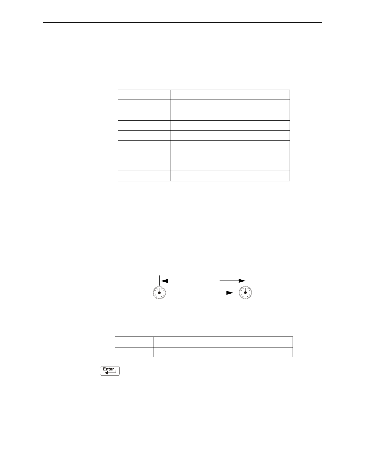
How to Program a Releasing Zone Releasing Applications
0
15
30
45
Delay = 15
(15 seconds)
All outputs Releasing
Zone R1 activate.
Initiating device(s) in
Releasing Zone R1
activates.
0
15
30
45
A.1.2 NFPA Releasing Applications
This control panel can be used for agent release or preaction/deluge control applications. In a
properly configured system with compatible, listed actuating and initiating devices, this control
panel complies with the following NFPA standards for installation in accordance with the
acceptable standard:
Table A.2 NFPA Standards for Releasing Applications
Standard Covers
NFPA 12 CO
NFPA 12A Halon 1301 Extinguishing Systems
NFPA 13 Sprinkler Systems, Installation of
NFPA 15 Water Spray Fixed Systems
NFPA 16 Foam-water Deluge and Foam-water Spray Systems
NFPA 17 Dry Chemical Extinguishing Systems
NFPA 17A Wet Chemical Extinguishing Systems
NFPA 2001 Clean Agent Fire Extinguishing Systems
Extinguishing Systems
2
A.2 How to Program a Releasing Zone
This section provides details for programming the releasing functions: Delay Timer, Abort Switch,
Cross Zone, and Soak Timer.
A.2.1 Programming a Delay Timer
Use a Delay Timer to specify the elapsed time between alarm activation of an initiating device and
activation of all output devices programmed as release circuits and mapped to that initiating device.
You can set the Delay Timer from 01 to 60 seconds, or to 00 for no delay. The figure below shows
graphical representation of a 15-second timer:
Figure A.1 Example of 15-Second Delay Timer
To Program Do this
Delay Timer Enter a value (00-60) from the numeric keys on the keyboard.
Press at this point to save the Delay Timer value if no other fields on the screen are
changing. To change another field on the screen, move the cursor into position by pressing the
arrow keys.
NFS2-640/E Programming Manual — P/N 52742:L2 7/17/14 61
Page 62
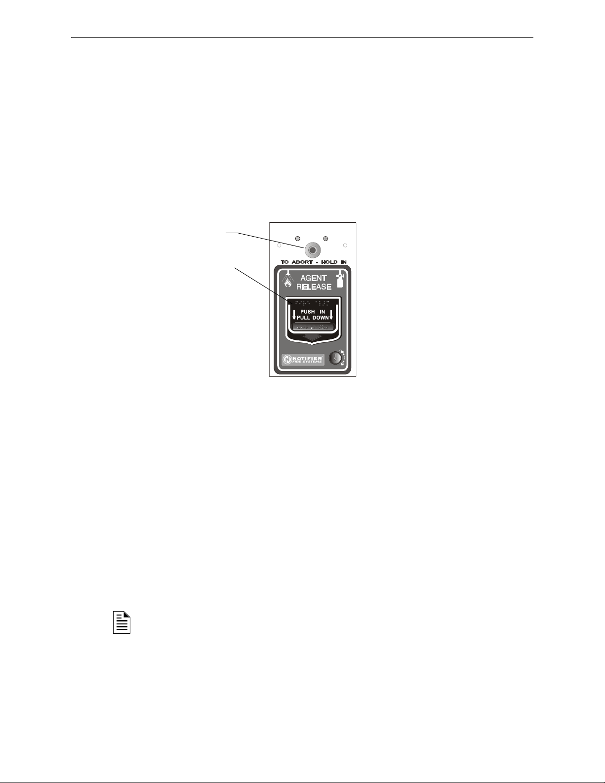
Releasing Applications How to Program a Releasing Zone
SYSTEM
NORMAL
SYSTEM
ACTIVATED
Abort Switch
Manual Agent
Release lever
NBG-12LRA station with Abort Switch
NBG12LRAface.wmf
A.2.2 Abort Switches
Definition of Abort Switches
The control panel provides for four (4) types of Abort Switches (ULI, IRI, NYC, and AHJ) that you
can use, that will affect the operation of a Delay Timer mapped to the same Releasing Zone. For
example, an Abort Switch selected for Releasing Zone R05 only affects the Delay Timer selected
for R05. Other requirements for using an Abort Switch include the following:
• Connecting a monitor module to a UL-listed abort station, such as the NBG-12LRA shown
below.
• Program the monitor module with the Type Code
Addressable Monitor Module Point” on page 22.)
• Abort switch shall not be used with a preaction system or a CO
ABORT SWITCH. (Refer to “Modify an
system.
2
Figure A.2 UL-listed Abort Station
This section contains information for programming each type of Abort Switch for a Releasing
Zone.
How an Abort Switch Works
The figure below contains an example for configuring an Abort Switch and shows the requirements
for using an Abort Switch for Releasing Zone R05, which are:
• A monitor module is wired to an abort station
• The monitor module is programmed with the Type Code,
• All initiating devices and outputs are mapped to a common Releasing Zone (R05 shown)
• Releasing Zone R05 is programmed with the releasing functions: Delay, Abort, Cross, and
Soak
NOTE: The abort switch can only be associated with one releasing zone.
ABORT SWITCH
62 NFS2-640/E Programming Manual — P/N 52742:L2 7/17/14
Page 63
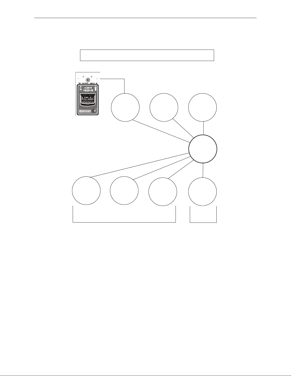
How to Program a Releasing Zone Releasing Applications
SYSTEM
NORMAL
SYSTEM
ACTIVATED
Type Code
RELEASE CKT
Type Code
REL CKT ULC
Type Code
REL AUDIBLE
Type Code
REL END BELL
Releasing Zone R05 sample programming selections
Example: If you program B01-B03 as shown,
these outputs activate at release.
Example: If you
program B04 as
shown, this output
activates when the
release is finished.
R05
Monitor
Module with
ABORT SWITCH
Type Code
Detector
Detector
Abort station with Abort Switch
and Manual Release lever
B01
B02
B03
B04
PRG RELEASE FUNCT RELEASE CONTROL
DELAY=15 ABORT=ULI CROSS=N SOK=0000 R05
When an initiating device activates, you must press and hold the Abort Switch or the control panel
will send the command to dump releasing agents when the Delay time (15 seconds shown) expires.
The Abort selection (ULI, IRI, NYC, or AHJ) determines the function of the Abort Switch.
Figure A.3 Example of a Basic Configuration for an Abort Switch
NFS2-640/E Programming Manual — P/N 52742:L2 7/17/14 63
Page 64
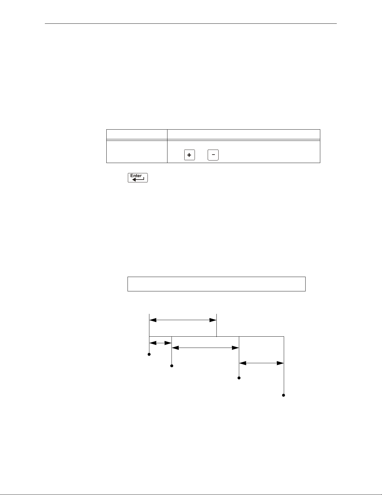
Releasing Applications How to Program a Releasing Zone
Release the Abort
Switch; the 10-second
ULI timer begins
Press and hold the
Abort Switch for 15
seconds
When the 10-seconds
ULI timer expires, the
control panel activates
Releasing Zone outputs
10 sec.
Program selections for Releasing Zone R05
Total time from alarm initiation to release:
5 + 15 + 10 = 30 seconds
Alarm
PRG RELEASE FUNCT RELEASE CONTROL
DELAY=15 ABORT=ULI CROSS=N SOK=0000 R05
15 sec.
5 sec.
0 sec.
5 sec.
15 sec.
Delay =15 sec.
20 sec.
30 sec.
Programming a ULI Abort Switch
The following contains information needed to program a ULI Abort Switch.
Description
Requires a standard UL-type delay timer that complies with UL Standard 864.
How to Program
1. Program the monitor module connected to the abort station with the Type Code
SWITCH as detailed in “Modify an Addressable Monitor Module Point” on page 22.
2. Select a time for the Releasing Zone Delay Timer (refer to“Programming a Delay Timer”
on page 61).
To P r o gram D o t his
ULI Abort Switch Type ULI in the ABORT= field, or press the
keys: or until ULI appears in the field.
NEXT or PREVIOUS
3. Press at this point to save the Abort Switch value if no other fields on the screen
are changing. To change another field on the screen, move the cursor into position by
pressing the arrow keys on the keypad.
ABORT
How It Works
When an alarm initiates in the programmed Releasing Zone, you can press and hold the Abort
Switch while the Delay Timer continues to count down. (If the delay timer has expired, the abort
switch has no effect.) When you release the Abort Switch, a 10-second ULI timer counts down. At
the end of the 10-second ULI timer, the control panel activates the Releasing Zone outputs.
Example
A ULI Abort Switch and a Delay Timer programmed to Releasing Zone R05:
64 NFS2-640/E Programming Manual — P/N 52742:L2 7/17/14
Figure A.4 ULI Abort Switch Example
Page 65

How to Program a Releasing Zone Releasing Applications
!
Program selections for Releasing Zone R05
PRG RELEASE FUNCT RELEASE CONTROL
DELAY=15 ABORT=IRI CROSS=Z SOK=0000 R05
Release the abort
switch; a 10-second
IRI timer begins
Press and hold
the Abort
Switch for 15
seconds
Alarm 1
Alarm 2
(Cross-zone
conditions met)
At the end of the 10 seconds,
the control panel activates
releasing zone outputs
Total time from when Abort
Switch is pressed to output
activation: 15 + 10 = 25
Total time from when Abort
Switch is released to output
activation: 10 seconds
0 sec.
5 sec.
5 sec.
5 sec.
10 sec.
10 sec.
10 sec.
20 sec.
30 sec.
Abort Switch held 15 sec.
Programming an IRI Abort Switch
The following contains information needed to program an IRI Abort Switch.
Description
A standard UL-type delay timer (complies with UL Standard 864) that operates like ULI, but with
additional functions for Cross Zones.
How to Program
1. Program the monitor module connected to the abort station with Type Code
detailed in “Modify an Addressable Monitor Module Point” on page 22.
2. Select a time for the Releasing Zone Delay Timer (refer to“Programming a Delay Timer”
on page 61.)
To P r o gram D o t his
IRI Abort Switch
Type IRI in the ABORT= field, or press the next or previous keys,
or , until IRI appears in the field.
3. Press at this point to save the Abort Switch value if no other fields on the screen
are changing. To change another field on the screen, move the cursor into position by
pressing the arrow keys on the keypad.
How it Works
ABORT SWITCH as
When the first alarm occurs in a releasing zone programmed with a cross-zone code, pressing the
abort switch will prevent activation of the releasing zone should a second alarm occur while the
switch is held. When the abort switch is released, if a second alarm has occurred while the switch
was held, the ten-second IRI timer activates immediately, and the control panel activates the
releasing zone outputs at the end of the IRI timer countdown. When the abort switch is released and
a second alarm has not occurred while the switch was held, the panel waits for the cross-zone
conditions to be met before activating the releasing zone.
WARNING:
The IRI abort switch will only work if it is pushed before the second alarm occurs. If it is pushed after the
second alarm, the releasing zone will already have been activated, and the switch will have no effect.
Example
An IRI Abort Switch and a Delay Timer programmed to Releasing Zone R05:
NFS2-640/E Programming Manual — P/N 52742:L2 7/17/14 65
Figure A.5 IRI Abort Switch Example
Page 66

Releasing Applications How to Program a Releasing Zone
Programming a NYC Abort Switch
The following contains information needed to program an NYC Abort Switch.
Description
A standard NYC delay timer that adds 90 seconds to the programmed Delay Timer.
NOTE: NYC timers do not comply with UL Standard 864.
How to Program
1. Program the monitor module connected to the abort station with the Type Code
SWITCH as detailed in “Modify an Addressable Monitor Module Point” on page 22.
2. Select a time for the Releasing Zone Delay Timer (refer to“Programming a Delay Timer”
on page 61).)
To P r o gram D o t his
NYC Abort Switch Type NYC in the ABORT= field, or press the next or previous keys,
or , until NYC appears in the field.
ABORT
3. Press at this point to save the Abort Switch value if no other fields on the screen
are changing. To change another field on the screen, move the cursor into position by
pressing the arrow keys on the keypad.
How It Works
When an alarm initiates in the programmed Releasing Zone, pressing and holding the Abort switch
stops the Delay Timer countdown. The Delay Timer restarts at the beginning of its countdown
when the Abort switch is released. When the Delay Timer expires, the 90-second NYC timer starts
counting down. When both timers expire, the control panel activates Releasing Zone outputs.
NOTE: 120 seconds is the maximum delay after the Abort switch is released. If the Delay Timer
time plus the NYC delay time of 90 seconds exceeds 120 seconds, Releasing Zone outputs will
still be activated at 120 seconds after the Abort switch is released.
Example 1 - Delay Time Does Not Exceed 120 Seconds
Select a Delay Timer value for R05 of 15 seconds. The Releasing Zone activates and the 15-second
Delay Timer starts. Ten seconds into the Delay Timer countdown, press and hold the Abort Switch
for 30 seconds, then release the Abort Switch. The control panel restarts the Delay Timer at 15
seconds and adds the NYC delay of 90 seconds. The delay timers will both expire at 105 seconds,
66 NFS2-640/E Programming Manual — P/N 52742:L2 7/17/14
Page 67
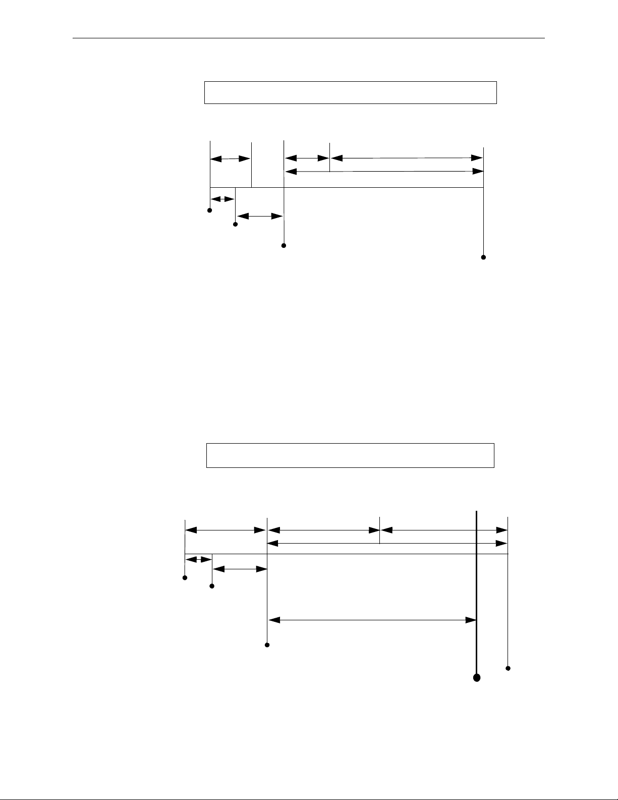
How to Program a Releasing Zone Releasing Applications
Press and hold
the Abort Switch
When all timers are expired (in this example,
145 seconds after alarm initiation, 105
seconds after the Abort switch has been
released) the control panel activates
Releasing Zone outputs
Program selections for Releasing Zone R05
Total time from alarm initiation to release:
10 + 30 + 105 = 145 seconds
Alarm
Release Abort Switch--At this point, the delay time
becomes the programmed delay
(15 sec.) plus 90 seconds (105
sec.) OR 120 seconds,
whichever is smaller
PRG RELEASE FUNCTION RELEASE CONTROL
DELAY=15 ABORT=NYC CROSS=N SOK=0000 R05
0 sec.
10 sec.
30 sec.
Delay=15 sec.
NYC Delay=90 sec.
105 sec. (15 + 90). Does not exceed 120 seconds.
Delay=15 sec.
Press and hold
the Abort Switch
The control panel activates
Releasing Zone outputs after
120 seconds have elapsed.
The NYC timer has not
expired, but it is overridden by
the control panel.
Program selections for Releasing Zone R05
Total time from alarm initiation to release:
10 + 30 + 60 + 60 = 160 seconds
Alarm
Release Abort Switch--At this point, the delay becomes
the balance of the programmed
delay (60 sec.) plus 90 seconds
(150 sec.) OR 120 seconds,
whichever is smaller
PRG RELEASE FUNCTION RELEASE CONTROL
DELAY=60 ABORT=NYC CROSS=N SOK=0000 R05
0 sec.
Delay=60 sec.
10 sec.
30 sec.
Delay=60 sec.
Pressing and releasing Abort switch
restarts Delay=60 countdown after
40 seconds have elapsed.
NYC Delay=90 sec.
150 sec. (60 + 90). Exceeds 120 seconds.
120 sec. to release
and Releasing Zone outputs will begin releasing at that time. Following is an example of a NYC
Abort Switch and a Delay Timer programmed to Releasing Zone R05:
Figure A.6 NYC Abort Switch Example 1
Example 2 - Delay Time Exceeds 120 Seconds
Select a Delay Timer value for R05 of 60 seconds. The Releasing Zone activates and the 60-second
Delay Timer starts. Ten seconds into the Delay Timer countdown, press and hold the Abort Switch
for 30 seconds, then release the Abort Switch. The control panel restarts the Delay Timer at 60
seconds and adds the NYC delay of 90 seconds. The delay timers will both expire at 150 seconds:
however, this time exceeds the maximum of 120 seconds, so the Releasing Zone outputs will begin
releasing at 120 seconds, not at 150. Following is an example of a NYC Abort Switch and a Delay
Timer programmed to Releasing Zone R05:
NFS2-640/E Programming Manual — P/N 52742:L2 7/17/14 67
Figure A.7 NYC Abort Switch Example 2
Page 68

Releasing Applications How to Program a Releasing Zone
Programming an AHJ Abort Switch
The following contains information needed to program an AHJ Abort Switch:
Description
An AHJ (Authority Having Jurisdiction) delay timer that restores the programmed Delay Timer.
NOTE: An AHJ timer does not comply with UL Standard 864.
How to Program
1. Program the monitor module connected to the abort station with the Type Code
SWITCH as detailed in “Modify an Addressable Monitor Module Point” on page 22.
2. Select a time for the Releasing Zone Delay Timer (refer to“Programming a Delay Timer”
on page 61.
To P r o gram D o t his
AHJ Abort Switch
Type AHJ in the ABORT= field, or press the NEXT or PREVIOUS keys,
or , until AHJ appears in the field.
3. Press at this point to save the Abort Switch value if no other fields on the screen
are changing. To change another field on the screen, move the cursor into position by
pressing the arrow keys on the keypad.
ABORT
How It Works
When an alarm initiates, the programmed Delay Timer starts. Press and hold the Abort switch and
the control panel suspends the Delay Timer. When you release the Abort Switch, the control panel
restores the value of the programmed Delay Timer and the Delay Timer counts down. When the
Delay Timer expires, the control panel activates Releasing Zone outputs.
68 NFS2-640/E Programming Manual — P/N 52742:L2 7/17/14
Page 69

How to Program a Releasing Zone Releasing Applications
Release the Abort Switch and control
panel restores the programmed value the
Delay Timer (60 sec.) and counts down
Press and hold
the Abort Switch
When the Delay Timer
expires, the control panel
activates Releasing
Zone outputs
Program selections for Releasing Zone R05
Total time from alarm initiation to release:
45 + 30 + 60 = 135 seconds
Alarm
PRG RELEASE FUNCTION RELEASE CONTROL
DELAY=60 ABORT=AHJ CROSS=N SOK=0000 R05
30 sec.
60 sec.
135 sec.
75 sec.
Delay=60 sec.
45 sec.
0 sec.
45 sec.
60 sec.
Example
An AHJ Abort Switch and a Delay Timer programmed to Releasing Zone R05:
Figure A.8 AHJ Abort Switch Example
NFS2-640/E Programming Manual — P/N 52742:L2 7/17/14 69
Page 70
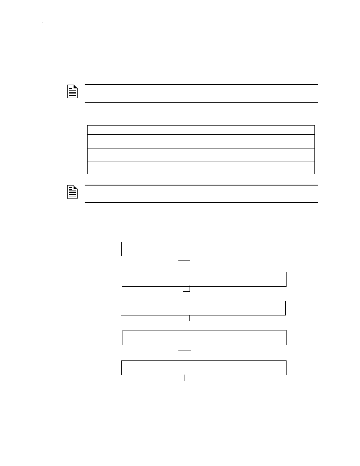
Releasing Applications How to Program a Releasing Zone
CBE list = 01 R1
CBE list = 01 R1
CBE list = 02 R1
CBE list = 02 R1
CBE list = R1
PROGRM SMOKE(PHOTO) DETECTOR ADDR 2D101
01 R1 __ __ __A8P8** 2D101
PROGRM SMOKE(PHOTO) DETECTOR ADDR 2D102
01 R1 __ __ __A8P8** 2D102
PROGRM SMOKE(PHOTO) DETECTOR ADDR 2D103
02 R1 __ __ __A8P8** 2D103
PROGRM HEAT(ANALOG) DETECTOR ADDR 2D104
02 R1 __ __ __ ** 2D104
PROGRM RELEASE CKT FRONT HALLWAY NO. 3
R1 __ __ __ __ I** B03
A.2.3 Using Cross Zones
Purpose of Cross Zones
Using Cross Zones lets you program the control panel to activate a Releasing Zone and any output
mapped to the Releasing Zone only after a predetermined sequence of events occurs. (If not using
Cross Zones, set CROSS= N.)
NOTE: Only the first Software Zone (Z01-Z99) listed in the zone map is used to determine
Cross=Z.
A summary of the types of Cross Zones and the conditions for activating a Releasing Zone:
Type Activates when
Y Two or more detectors or modules are alarmed that are mapped to one of the ten Releasing Zones
Z Two or more detectors or modules are alarmed that are mapped to two different software zones
H At least one smoke detector or module mapped to one of the ten Releasing Zones (R0-R9) is
(R0-R9).
and mapped to one of the ten Releasing Zones (R0-R9).
alarmed and at least one heat detector mapped to the same Releasing Zone (R0-R9) is alarmed.
NOTE: When in alarm, Special Zones R0-R9 appear in the CBE list as ZR00-ZR09. For
example, R5 appears in the CBE list as ZR05.
How Cross Zones Work
Below is an illustrated example of how Cross Zones work, using five Cross Zone selections (four
detectors and a NAC mapped to Releasing Zone R1):
70 NFS2-640/E Programming Manual — P/N 52742:L2 7/17/14
Page 71

How to Program a Releasing Zone Releasing Applications
Releasing
Zone ZR1
Software
Zone Z02
Software
Zone Z01
Smoke
Detector
2D102
Heat
Detector
2D104
Smoke
Detector
2D103
Smoke
Detector
2D101
REL
B03
CBE list = Z02 ZR1
CBE list = Z01 ZR1
CBE list = Z01 ZR1
CBE list = ZR1
Figure A.9 Illustrated Example of Cross Zone Programming
A listing of each Cross Zone option and the conditions required to activate the Releasing Zone,
according to the example shown above.
Cross Zone
Selection (Cross=)
Cross=N An alarm from any detector or module activates the releasing circuit.
Cross=Y An alarm from any two detectors or modules activates the releasing
Cross=Z An alarm from two detectors or modules mapped to different Software
Cross=H Activation of heat detector 2D104 and one smoke detector (2D101,
Condition(s) Required to Activate the Releasing zone
circuit.
Zones, but mapped to the same Releasing Zone.
• An alarm from 2D101 and 2D103
• An alarm from 2D102 and 2D104
• An alarm from 2D101 and 2D104
• An alarm from 2D102 and 2D103
The two detectors listed in each set above are each mapped to different
zones, but both list ZR1 in their CBE.
21D102, or 2D103) or a module mapped to the same releasing zone.
Select a time for the Releasing Zone Delay Timer (refer to“Programming a Delay Timer” on page
61.)
To Program Do this
Cross Zones Type N, Y, Z, or H in the CROSS= field, or press the
NEXT or PREVIOUS keys,
or , until N, Y, Z or H appears in the that field.
NFS2-640/E Programming Manual — P/N 52742:L2 7/17/14 71
Page 72

Releasing Applications How to Program a Releasing Zone
PRG RELEASE FUNCTION RELEASE CONTROL
DELAY=00 ABORT=ULI CROSS=N SOK=0600 R00
Press at this point to save the Cross Zone value if no other fields on the screen are
changing. To change another field on the screen, move the cursor into position by pressing the
arrow keys on the keypad.
A.2.4 Programming a Soak Timer
The Soak Timer specifies the length of time (0001 to 9999 seconds, or 0000 for not used) to dump
releasing agents when a Releasing Zone activates. When the Soak Timer expires, the control panel
automatically shuts off the releasing solenoids for the active Releasing Zone. To program a Soak
Timer for a Releasing Zone, follow these instructions:
To Program Do this
Soak Timer Type a seconds value of 0000 (no soak timer) to 9999 from the
numeric keys on the keypad in the SOK= field.
Press at this point to save the Soak Timer value if no other fields on the screen are
changing. To change another field on the screen, move the cursor into position by pressing the
arrow keys on the keypad.
A Soak Timer value of 600 seconds is shown below:
72 NFS2-640/E Programming Manual — P/N 52742:L2 7/17/14
Page 73

How to Program a Releasing Zone Releasing Applications
A.2.5 Using Type Codes for Releasing Zones
The control panel provides a set of Type Codes designed for releasing applications for inputs and
outputs. This section details how to program each of these Type Codes.
Type Codes designed for Releasing Zone inputs (monitor modules).
Type Code What the Type Code does Refer to
ABORT SWITCH
(tracking)
Provides an abort function through a monitor
module (connected to a UL-listed abort
“abort switch Type Code” on page 74
station) for a Releasing Zone.
MAN. RELEASE
(latching)
Provides a manual release through a monitor
module (connected to a UL-listed pull station)
“man. release Type Code” on page
75
for a Releasing Zone.
MAN REL DELAY
(latching)
Provides a manual release with a 30-second
delay (dependent on the FACP Delay setting)
“manrel delay Type Code” on page
76
through a monitor module (connected to a
UL-listed pull station) for a Releasing Zone.
SECOND SHOT
(latching)
Provides a second manual release through a
monitor module (connected to a UL-listed
“second shot Type Code” on page 78
pull station) for a Releasing Zone.
Type Codes designed for Releasing Zone outputs (control modules and panel NACs).
Type Code What the Type Code does Refer to
REL END BELL Activates a NAC audio or visual device
when releasing circuits shut off.
REL CKT ULC Directs outputs to perform a release function
as required by ULC.
RELEASE CKT Directs outputs to perform a releasing
function.
“release end bell” on page 79
“rel ckt ulc Type Code” on page 81
“release ckt Type Code” on page 83
RELEA. FORM C Directs relay outputs to perform a releasing
function.
REL AUDIBLE Activates audio or visual devices steady
when releasing starts.
INSTANT RELE Activates non-releasing output (panel NAC
or control modules) with no delay time.
REL CODE BELL Activates audio or visual devices to pulse at
20 ppm (initial zone of a Cross Zone) or 120
ppm (Cross Zone satisfied).Steady on
release.
“Relea. Form-C Type Code” on page
85
“rel audible Type Code” on page 87
“instant rele Type Code” on page 89
“REL CODE BELL Type Code” on
page 90
NFS2-640/E Programming Manual — P/N 52742:L2 7/17/14 73
Page 74
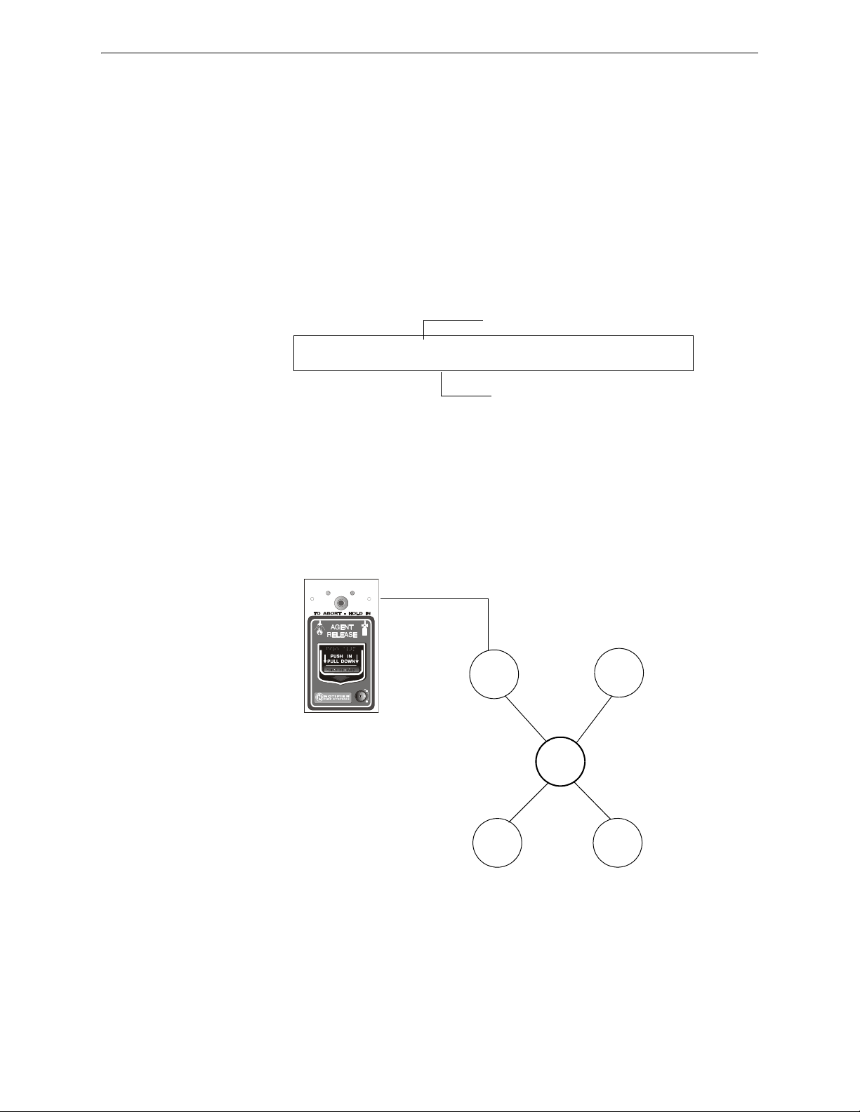
Releasing Applications How to Program a Releasing Zone
Releasing Zone selection (R1 shown)
Type Code selection: ABORT SWITCH
PROGRM ABORT_SWITCH MODULE ADDR 2M101
R1 __ __ __ __ 2M101
SYSTEM
NORMAL
SYSTEM
ACTIVATED
Detector
Control
Module
R05
NBG-12LRA
station with
Abort Switch
B01
Monitor
Module
Type Code
ABORT SWITCH
NBG12LRAface.wmf
ABORT SWITCH Type Code
The following contains information needed to program an Abort Switch for a monitor module
Description
A monitor module, connected to a UL-listed abort station (such as the Notifier NBG-12LRA), that
you use as an abort switch for a Releasing Zone. You can program multiple monitor modules with
the
ABORT SWITCH Type Code that work like multiple conventional abort switches on a
conventional zone.
Programming
1. Select a monitor module to use as an Abort Switch (refer to “Modify or Delete a Point
(2=point)” on page 19).
2. Select the
ABORT SWITCH Type Code.
3. Select the Releasing Zone (R0-R9) for your releasing application.
4. Press the enter key to save, then press the esc key until you return to the Program Change
screen.
5. Select the type of Abort Switch for your releasing application (refer to “Abort Switches” on
page 62).
Example
A programming example of a monitor module programmed as an Abort Switch for Releasing Zone
R5.
Figure A.10 Monitor Module Configured as an Abort Switch
74 NFS2-640/E Programming Manual — P/N 52742:L2 7/17/14
Page 75
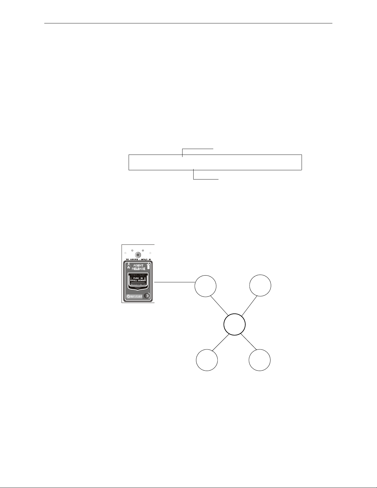
How to Program a Releasing Zone Releasing Applications
Releasing Zone selection (R5 shown)
Type Code selection: MAN RELEASE
PROGRM MAN_RELEASE MODULE ADDR 2M101
R5 __ __ __ __ 2M101
SYSTEM
NORMAL
SYSTEM
ACTIVATED
Detector
Control
Module
R05
NBG-12LRA station with Manual Release Lever
B01
Monitor
Module
Type Code
MAN. RELEASE
NBGLRAface.wmf
MAN. RELEASE Type Code
The following contains information needed to program a Manual Release switch for a monitor
module
.
Description
A monitor module—connected to a UL-listed manual station (such as the Notifier NBG-12LRA)—
used to manually release agents. A Manual Release switch overrides all timers, such as a Delay
Timer or a Soak Timer. You can install multiple monitor modules with a
MAN. RELEASE Type Code
that work like multiple conventional manual release switches on a conventional zone.
Programming
1. Select a monitor module (refer to “Modify or Delete a Point (2=point)” on page 19) to use for
the manual release function.
2. Select the
MAN. RELEASE Type Code.
3. Select the Releasing Zone (R0-R9) for your releasing application.
4. Press the
ENTER key to save, then press the ESC key until you return to the Program Change
screen.
Example
A programming example of a monitor module programmed as an manual release switch for
Releasing Zone R5.
Figure A.11 Monitor Module Configured as a Manual Release Switch
NFS2-640/E Programming Manual — P/N 52742:L2 7/17/14 75
Page 76

Releasing Applications How to Program a Releasing Zone
Releasing Zone selection (R5 shown)
Type Code selection:
MANREL_DELAY
PROGRM MANREL_DELAY MODULE ADDR 2M101
R5 __ __ __ __ 2M101
MANREL DELAY Type Code
The following contains information needed to program a Manual Release Delay switch for a
monitor module using the
Description
MANREL DELAY Type Code.
A monitor module—connected to a UL-listed manual station (such as the Notifier NBG-12LRA)—
used to initiate a manual release with 30-second delay time.
A Manual Release Delay switch overrides the FACP programmed Delay Timer in certain
circumstances, but not the soak timer.
Override Circumstances:
When the Manual Release Delay Switch activates, the control panel replaces the Delay Time
with 30 seconds if the Delay Timer
• is set to more than 30 seconds
•is running, and
• has not counted down below 30 seconds.
NOTE: When the Delay Timer is set to less than 30 seconds, activation of the Manual Release
Delay Switch will invoke the FACP programmed Delay Time if the Delay Timer is not running, or
the FACP programmed Delay Timer countdown time if it is running. Refer to the examples 1
through 5 later in this section.
Multiple monitor modules can be programmed with a
MANREL DELAY Type Code. They work like
multiple conventional manual release switches on a conventional zone.
How to program
1. Select a monitor module (refer to “Modify or Delete a Point (2=point)” on page 19) to use
for the manual release function.
2. Select the
MANREL DELAY Type Code.
3. Select the Releasing Zone (R0-R9) for your releasing application.
4. Press the
ENTER key to save, then press the ESC key until you return to the Program
Change screen.
76 NFS2-640/E Programming Manual — P/N 52742:L2 7/17/14
Page 77
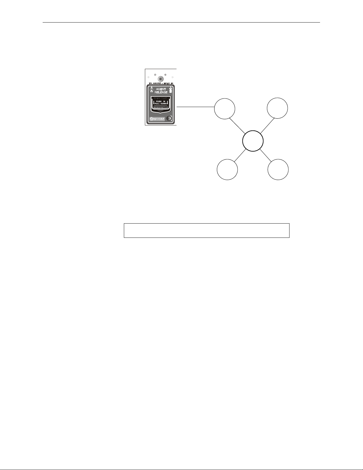
How to Program a Releasing Zone Releasing Applications
SYSTEM
NORMAL
SYSTEM
ACTIVATED
Detector
Control
Module
R05
NBG-12LRA
station with
Manual Release
Lever
B01
Monitor
Module
Type Code
MANREL DELAY
NBGLRAface.wmr
PRG RELEASE FUNCTION RELEASE CONTROL
DELAY=60 ABORT=ULI CROSS=N SOK=0030 R05
Examples
A programming example of a monitor module programmed for
MANREL DELAY switch for
Releasing Zone R5.
Figure A.12 Monitor Module Configured as a Manual Release Delay Switch
For examples 1, 2, and 3, program Releasing Zone R5 with a Manual Release Delay switch and the
following releasing selections:
Example 1 - The FACP programmed Delay Timer begins its 60 second countdown. The Manual
Release Delay switch is pulled when the FACP Delay Timer has counted down to 48 seconds
(elapsed time of 12 seconds). The 48 seconds remaining in the countdown are overridden by the 30second delay initiated by the Manual Release Delay switch. In this example, the total time elapsing
from FACP countdown initiation to agent release is 42 seconds (12 + 30), less than the original 60
second FACP Delay Timer countdown.
Example 2 - The FACP programmed Delay Time begins its 60 second countdown. The Manual
Release Delay switch is pulled when the FACP Delay Timer has counted down to 8 seconds. The 8
seconds remaining in the countdown is not changed when the switch is pulled. In this example, the
total time elapsing from FACP countdown initiation to agent release is 60 seconds.
Example 3 - The FACP programmed Delay Time is not running (as would happen if the releasing
station were pulled before an alarm registered). The Manual Release Delay Switch is activated by
the pull station. Agent release will occur in 30 seconds.
For examples 4 and 5, the delay is changed to
Example 4 - The FACP programmed Delay Timer begins its 10 second countdown. The Manual
Release Delay switch is pulled when the FACP Delay timer has counted down to 8 seconds. The 8
seconds remaining in the countdown is not changed. In this example, the total time elapsing from
FACP countdown initiation to agent release is 10 seconds.
Example 5 - The FACP programmed Delay Timer is not running (as would happen if the releasing
station were pulled before an alarm registered). The Manual Release Delay switch is activated by
the pull station. Agent release will occur in 10 seconds.
DELAY=10.
NFS2-640/E Programming Manual — P/N 52742:L2 7/17/14 77
Page 78
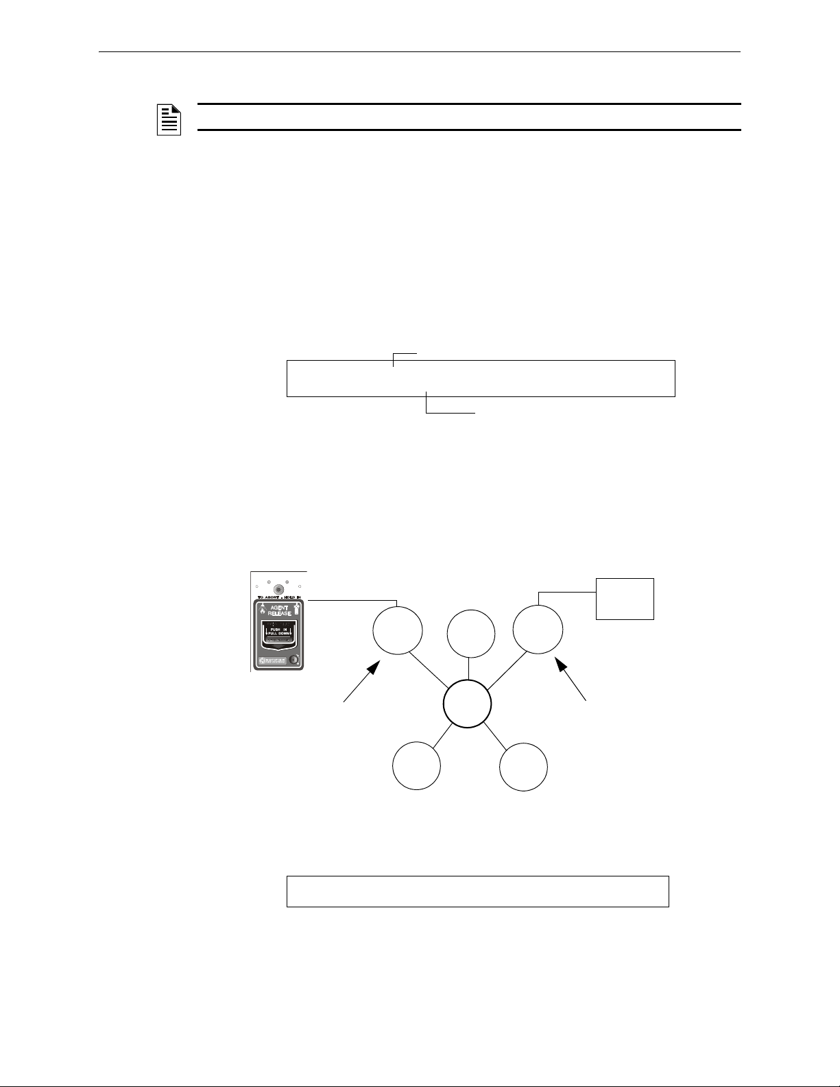
Releasing Applications How to Program a Releasing Zone
Type Code selection: SECOND_SHOT
Releasing Zone selection (R5 shown)
PROGRM SECOND_SHOT MODULE ADDR 2M101
R5 __ __ __ __ 2M101
SYSTEM
NORMAL
SYSTEM
ACTIVATED
NBG-12LRA station with
Manual Release lever
R05
Detector
B01
Monitor
Module
2M101
Monitor
Module
2M102
Type Code
MANREL DELAY
Control
Module
Type Code
SECOND SHOT
Second
Shot
Switch
PRG RELEASE FUNCTION RELEASE CONTROL
DELAY=15 ABORT=ULI CROSS=Y SOK=0030 RO5
SECOND SHOT Type Code
NOTE: The Second Shot switch can only be used with the MANREL DELAy Type Code.
The following contains information needed to program a Second Shot switch for a monitor module
Description
A monitor module—connected to a UL-listed manual station (such as the NBG-12LRA)—used as
for a second release of agents. A Second Shot switch overrides a Delay Timer, programmed to the
same Releasing Zone.
Programming
1. Select a monitor module (refer to “Modify or Delete a Point (2=point)” on page 19) to use for
the manual release function.
2. Select the
SECOND SHOT Type Code.
3. Select the Releasing Zone (R0-R9) for your releasing application.
4. Press the
ENTER key to save, then press the ESC key until you return to the Program Change
screen.
Examples
A programming example of a monitor module programmed as a Manual Release Delay switch
(Type Code
MANREL DELAY) for the first shot and a Second Shot switch (Type Code SECOND SHOT)
for the second shot.
Figure A.13 Monitor Module Configured as a Second Shot Switch
With two monitor modules configured as shown above, program Releasing Zone R5 with the
following releasing selections.
R05 can be activated in one of two ways, as described in the examples given below.
78 NFS2-640/E Programming Manual — P/N 52742:L2 7/17/14
Page 79
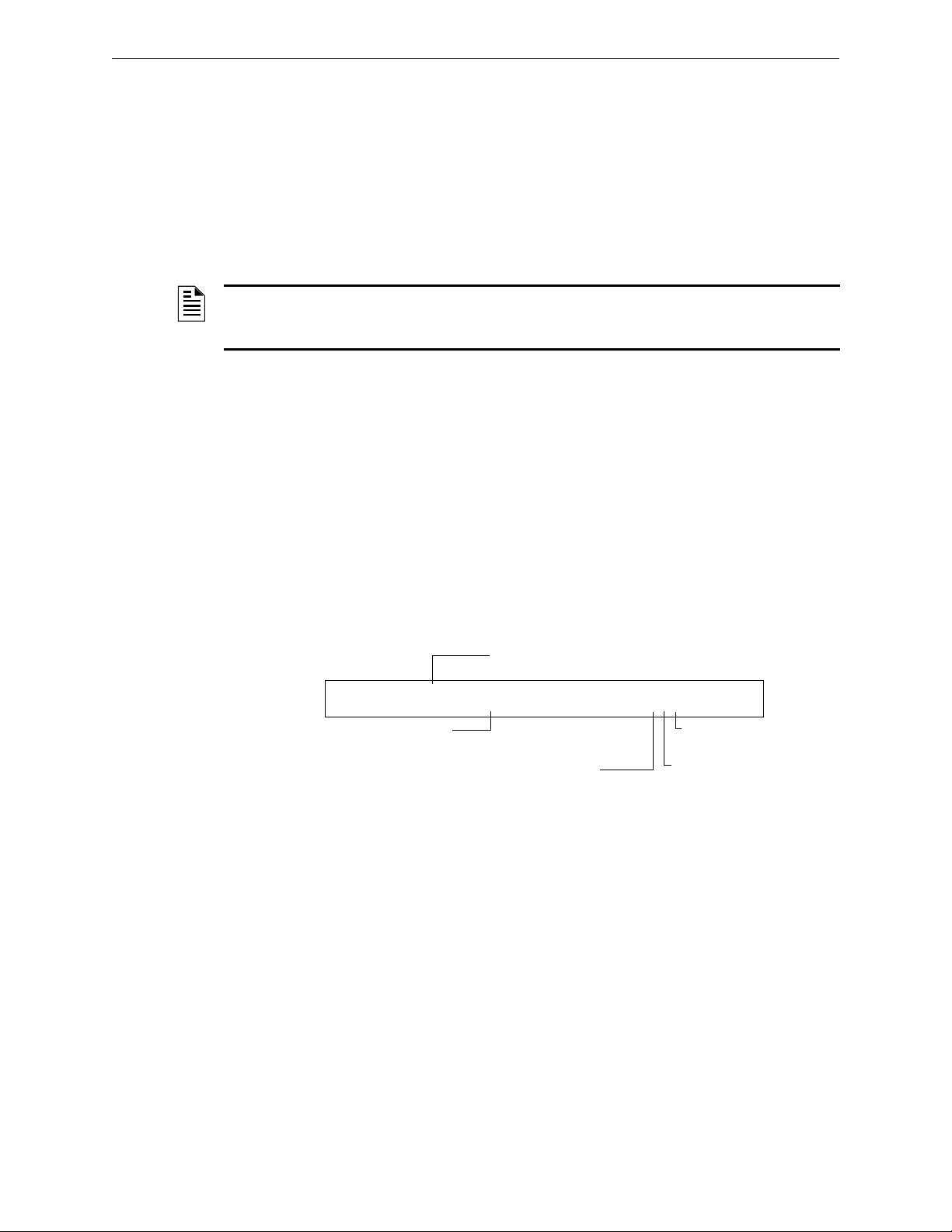
How to Program a Releasing Zone Releasing Applications
Type Code selection: REL END BELL
Releasing Zone
selection (R5 shown)
Walk Test
Selection: * = off
PROGRM REL END BELL MODULE ADDR 2M108
R5 __ __ __ __ I** 2M108
Switch Inhibit: I = selected
Silenceable: * = off
Example 1: If the detector initiates the alarm, R05 activates. Releasing begins after the delay timer
has expired (15 seconds). Releasing will continue for the soak timer duration (30 seconds). Once
the Soak Timer expires, the Second Shot Switch can then be activated to initiate an additional soak
cycle.
Example 2: If the NBG-12LRA (Type Code
MANREL DELAY) lever is pulled, the delay timer
begins its 15 second countdown. Releasing will begin after the delay timer has expired, and will
continue for the soak timer duration (30 seconds). Once the Soak Timer expires, the Second Shot
Switch can then be activated to initiate an additional soak cycle.
RELEASE END BELL
NOTE: A releasing circuit with this Type Code requires the following selections: A Releasing
Zone selection (R0-R9); An output circuit mapped to the same Releasing Zone; Switch Inhibit
selected; Non-Silenceable; No Walk Test.
The following contains information needed to program a Release End Bell circuit for a control
module or a NAC
Description
.
A control module or NAC to activate an audible or visual device when releasing devices shut off.
You can also program multiple outputs with the
Zone. When all the Releasing Zone functions are complete, all outputs with the
Code activate at the same time. A
Programming
REL END BELL circuit remains on until you reset the system
REL END BELL Type Code to the same Releasing
REL END BELL Type
1. Select a control module or NAC (refer to “Modify or Delete a Point (2=point)” on page 19) to
use as a Release End Bell circuit.
2. Select the
REL END BELL Type Code, as shown in the following example (control module
shown).
3. Select the Releasing Zone (R0-R9) for your releasing application.
4. Press the enter key to save, then press the esc key two times to return to the Program Change
screen.
NFS2-640/E Programming Manual — P/N 52742:L2 7/17/14 79
Page 80

Releasing Applications How to Program a Releasing Zone
Type Code
REL END BELL
Type Code
REL CIRCUIT
Type Code
REL CIRCUIT
Type Code
REL AUDIBLE
For example, a control module programmed with the REL END
BELL Type Code activates when all releasing functions, such
as the releasing functions programmed for R05 shut off.
Control
Module
B02
B01
Control
Module
R05
Monitor
Module
Detector
Detector
Detector
Example
A programming example of a control module programmed as a Release End Bell for Releasing
Zone R5.
Figure A.14 Control Module Configured as a Release End Bell Circuit
80 NFS2-640/E Programming Manual — P/N 52742:L2 7/17/14
Page 81
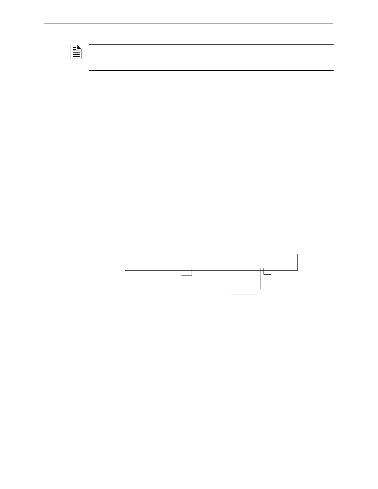
How to Program a Releasing Zone Releasing Applications
PROGRM REL CKT ULC MODULE ADDR 2M108
R5 __ __ __ __ I** 2M108
Walk Test
Selection: * = off
Silenceable: * = off
Type Code selection:
REL CKT ULC
Releasing Zone
selection (R5 shown)
Switch Inhibit: I = selected
REL CKT ULC Type Code
NOTE: A ULC Release Circuit with this Type Code requires the following selections: A
Releasing Zone selection (R0-R9); An output circuit mapped to the same Releasing Zone; Switch
Inhibit selected; Non-Silenceable; No Walk Test.
The following contains information needed to program a ULC Release Circuit for a control module
or a NAC
Description
.
A control module or a NAC used to activate a releasing solenoid or other releasing device. You can
also program multiple outputs with the
the Releasing Zone activates, all outputs with the
REL CKT ULC Type Code to the same Releasing Zone. When
REL CKT ULC Type Code also activate at the same
time. A ULC Release Circuit activates when:
• An initiating device programmed to the same Releasing Zone activates (two devices if using
the Cross Zone option)
• The Delay Timer for R0-R9 (if used) expires
• No Abort Switch for R0-R9 (if used) is active
A ULC Release Circuit—and all wiring to the release device—is fully supervised and usable with
power-limited energy cable.
Programming
1. Select a control module or a NAC (refer to “Modify or Delete a Point (2=point)” on page 19)
to use as a ULC Release Circuit.
2. Select the
REL CKT ULC Type Code, as shown in the following example (control module
shown).
3. Select the Releasing Zone (R0-R9) for your releasing application.
4. Press the
ENTER key to save, then press the ESC key two times to return to the Program Change
screen.
NFS2-640/E Programming Manual — P/N 52742:L2 7/17/14 81
Page 82

Releasing Applications How to Program a Releasing Zone
Type Code
REL CKT ULC
Control
Module
B02
B01
Control
Module
R05
Monitor
Module
Detector
Detec
Detector
Type Code
REL CKT ULC
For example, all control modules programmed with the REL
CKT ULC Type Code activate simultaneously with other
outputs programmed for R5 (B01, B02).
Example
A programming example of a control module programmed as a ULC Release Circuit for Releasing
Zone R5.
Figure A.15 Control Module Configured as a ULC Release Circuit
82 NFS2-640/E Programming Manual — P/N 52742:L2 7/17/14
Page 83

How to Program a Releasing Zone Releasing Applications
Type Code selection: RELEASE CKT
Releasing Zone
selection (R5 shown)
PROGRM RELEASE CKT MODULE ADDR 2M108
R5 __ __ __ __ I** 2M108
Walk Test
Selection: * = off
Silenceable: * = off
Switch Inhibit: I = selected
RELEASE CKT Type Code
NOTE: A Release Circuit with this Type Code requires the following selections: A Releasing
Zone selection (R0-R9); An output circuit mapped to the same Releasing Zone; Switch Inhibit
selected; Non-Silenceable; No Walk Test.
NOTE: Do not use a Release Circuit for the following: An application requiring ULC Listing; An
application requiring power-limited energy cable.
The following contains information needed to program a Release Circuit for an output circuit
(control module or NAC)
Description
.
A control module or a NAC used to activate a releasing solenoid or other releasing device. You can
also program multiple outputs with the
the Releasing Zone activates, all outputs associated with the releasing zone and with the
CKT Type Code also activate at the same time. A Release Circuit activates when:
RELEASE CKT Type Code to the same Releasing Zone. When
RELEASE
• An initiating device programmed to the same Releasing Zone activates (two devices if using
the Cross Zone option)
• The Delay Timer for R0-R9 (if used) expires
• The Abort Switch for R0-R9 (if used) is not active
Programming
1. Select a control module or a NAC (refer to “Modify or Delete a Point (2=point)” on page 19)
to use as a Release Circuit.
2. Select the
RELEASE CKT Type Code, as shown in the following example (control module
shown).
3. Select the Releasing Zone (R0-R9) for your releasing application.
4. Press the
ENTER key to save, then press the ESC key two times to return to the Program Change
screen.
NFS2-640/E Programming Manual — P/N 52742:L2 7/17/14 83
Page 84

Releasing Applications How to Program a Releasing Zone
Type Code
RELEASE CKT
Control
Module
B02
B01
Control
Module
R05
Monitor
Module
Detector
Detector
Detector
Type Code
RELEASE CKT
For example, all control modules programmed with the RELEASE
CKT Type Code activate simultaneously with other outputs
programmed for R5 (B01, B02).
Example
A programming example of a control module programmed as a Release Circuit for Releasing Zone
R5.
Figure A.16 Control Module Configured as a Release Circuit
84 NFS2-640/E Programming Manual — P/N 52742:L2 7/17/14
Page 85

How to Program a Releasing Zone Releasing Applications
Type Code selection: RELEA.FORM C
Releasing Zone
selection (R5 shown)
Walk Test
Selection: * = off
Silenceable: * = off
Switch Inhibit: I = selected
PROGRM RELEA.FORM C MODULE ADDR 2M108
R5 __ __ __ __ I** 2M108
Relea. Form-C Type Code
NOTE: An output with a relea.form c Type Code requires the following selections: A Releasing
Zone selection (R0-R9); An output circuit mapped to the same Releasing Zone; Switch Inhibit
selected; Non-Silenceable; No Walk Test.
The following contains information needed to program a Release Form-C circuit for an output
.
circuit
Description
An output circuit, configured as a relay, programmed to activate an output by opening or closing a
switch. Typical applications include closing doors and air handlers.
Programming
1. Select a control module (refer to “Modify or Delete a Point (2=point)” on page 19) to use as a
Releasing Form-C Circuit.
2. Select the
shown).
RELEA.FORM C Type Code, as shown in the following example (control module
3. Select the Releasing Zone (R0-R9) for your releasing application.
4. Press the
ENTER key to save, then press the ESC key two times to return to the Program Change
screen.
NFS2-640/E Programming Manual — P/N 52742:L2 7/17/14 85
Page 86

Releasing Applications How to Program a Releasing Zone
Type Code
REL FORM C
Type Code
REL CIRCUIT
Type Code
REL CIRCUIT
Type Code
REL AUDIBLE
For example, a control module, configured as a Form-C relay,
activates simultaneously with other outputs programmed for R5 (B01,
B02) and the control module with the
REL AUDIBLE Type Code.
Control
Module
B02
B01
Control
Module
R05
Monitor
Module
Detector
Detector
Detector
Example
A programming example of a control module programmed as a Release Form-C circuit for
Releasing Zone R5.
Figure A.17 Control Module Configured as a Release Form-C Circuit
86 NFS2-640/E Programming Manual — P/N 52742:L2 7/17/14
Page 87

How to Program a Releasing Zone Releasing Applications
Type Code selection: REL AUDIBLE
PROGRM REL AUDIBLE MODULE ADDR 2M108
R5 __ __ __ __ I** 2M108
Releasing Zone
selection (R5 shown)
Walk Test
Selection: * = off
Silenceable: * = off
Switch Inhibit: I = selected
REL AUDIBLE Type Code
NOTE: An output with a REL AUDIBLE Type Code requires the following selections: A Releasing
Zone selection (R0-R9); An output circuit mapped to the same Releasing Zone; Switch Inhibit
selected.
The following contains information needed to program a Release Audible circuit for an output
circuit (control module or NAC)
Description
.
An output circuit programmed to activate an audio or visual device when all releasing outputs,
programmed to the same Releasing Zone, turn on. You can also program multiple outputs with the
REL AUDIBLE Type Code to the same Releasing Zone. When the Releasing Zone activates, all
outputs with the
Programming
REL AUDIBLE Type Code activate at the same time.
1. Select a control module or NAC (refer to “Modify or Delete a Point (2=point)” on page 19) to
use as a Releasing Circuit.
2. Select the
REL AUDIBLE Type Code, as shown in the following example (control module
shown).
3. Select the Releasing Zone (R0-R9) for your releasing application.
4. Press the
ENTER key to save, then press the ESC key two times to return to the Program Change
screen.
NFS2-640/E Programming Manual — P/N 52742:L2 7/17/14 87
Page 88

Releasing Applications How to Program a Releasing Zone
Type Code
REL AUDIBLE
Type Code
REL CIRCUIT
Type Code
REL CIRCUIT
Type Code
REL AUDIBLE
For example, a control module programmed with the REL
AUDIBLE Type Code activates simultaneously with other
outputs programmed for R05 (B01 and B02).
Control
Module
B02
B01
Control
Module
R05
Monitor
Module
Detector
Detector
Detector
Example
A programming example of a control module programmed as a Release Audible circuit for
Releasing Zone R5.
Figure A.18 Control Module Configured as a Release Audible Circuit
88 NFS2-640/E Programming Manual — P/N 52742:L2 7/17/14
Page 89

How to Program a Releasing Zone Releasing Applications
Type Code selection: INSTANT REL
PROGRM INSTANT RELE MODULE ADDR 2M101
R5 __ __ __ __ I** 2M101
Releasing Zone
selection (R5 shown)
Walk Test
Selection: * = off
Silenceable: * = off
Switch Inhibit: I = selected
Type Code
INSTANT RELE
Control
Module
B02
B01
Control
Module
R05
Monitor
Module
Detector
Detector
Detector
Type Code
INSTANT RELE
For example, a control module programmed with the
INSTANT RELE Type Code activates simultaneously with
other outputs programmed for R05 (B01 and B02).
INSTANT RELE Type Code
NOTE: An output with an INSTANT RELE Type Code requires the following selections: a zone
selection (a releasing zone may be used, but is not required); an output circuit mapped to the
same zone; Switch Inhibit selected; Non-Silenceable; No Walk Test.
The following contains information needed to program an Instant Release circuit for an output
circuit (control module or NAC)
Description
.
An output circuit programmed to activate non-releasing devices, such as door openers or warning
sounders, without counting down delay timers. A device programmed with the
INSTANT RELE Type
Code device is supervised for open circuits and ground faults.
Programming
1. Select a control module or a NAC (refer to“Modify or Delete a Point (2=point)” on page 19) to
use as a Releasing Circuit.
2. Select the
INSTANT RELE Type Code, as shown in the following example (control module
shown).
3. Select the Releasing Zone (R0-R9) for your releasing application.
4. Press the
Example
ENTER key to save, then press the ESC key two times to return to the Program Change screen.
A programming example of a control module programmed as an Instant Release circuit for
Releasing Zone R5.
NFS2-640/E Programming Manual — P/N 52742:L2 7/17/14 89
Figure A.19 Control Module Configured as an Instant Release Circuit
Page 90
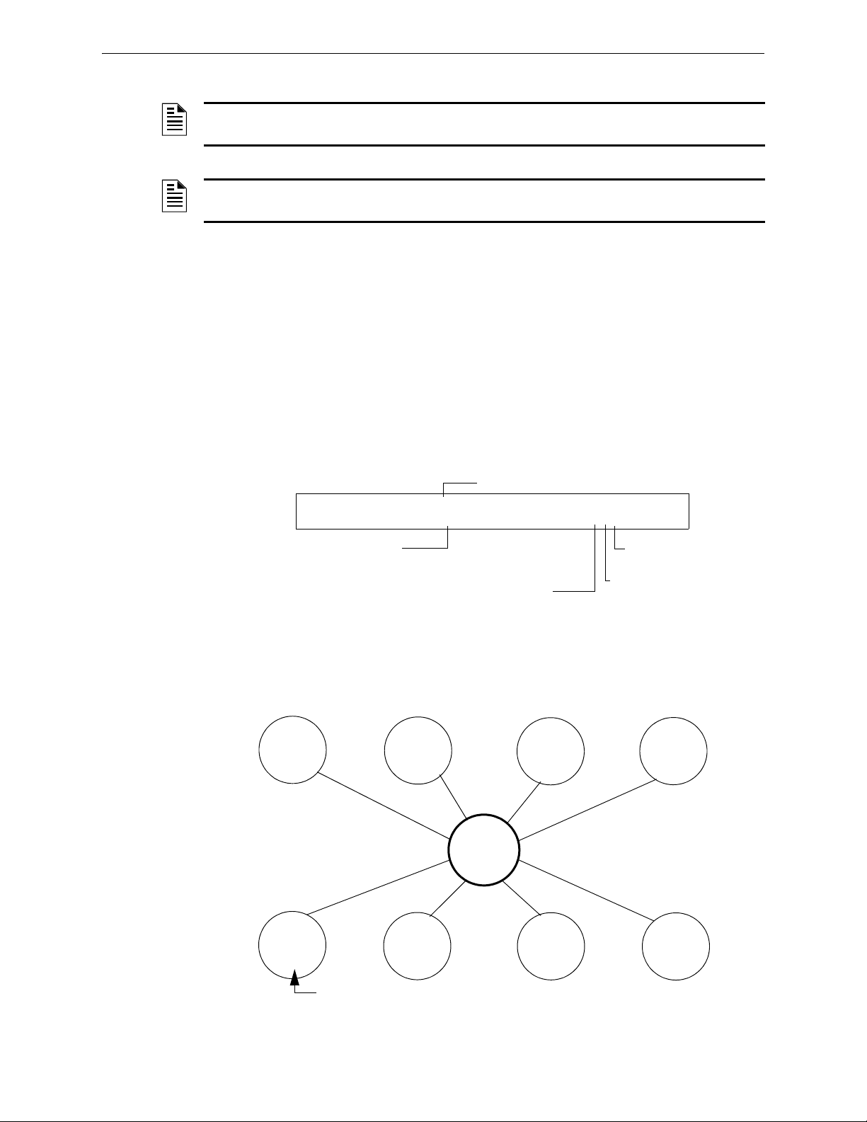
Releasing Applications How to Program a Releasing Zone
Type Code selection: REL CODE BELL
PROGRM REL CODE BELL FRONT HALLWAY NO. 3
R5 __ __ __ __ I** B03
Releasing Zone
selection (R5 shown)
Walk Test
Selection: * = off
Silenceable: * = off
Switch Inhibit: I = selected
Type Code
REL CODE BELL
Control
Module
B02
B01
B03
R05
Monitor
Module
Detector
Detector
Detector
A NAC programmed with the
REL CODE BELL Type Code activates
simultaneously with other outputs programmed for R05 (B01 and B02).
REL CODE BELL Type Code
NOTE: An output with a REL CODE BELL Type Code requires the following selections: A
Releasing Zone selection (R0-R9); An input circuit mapped to the same Releasing Zone.
NOTE: For instructions on programming Switch Inhibit, Silenceable, and Walk Test, refer to
“Modify NAC Points” on page 24.
The following contains information needed to program a Release Code Bell circuit for a NAC
Description
A NAC programmed to pulse an audio or visual device as follows:
• 20 ppm when a the initial zone of a cross-zone activates.
• 120 ppm when a Cross Zone is satisfied.
• Steady when a release occurs.
Programming
1. Select a NAC (refer to “Modify NAC Points” on page 24) to use as a Release Code Bell
Circuit.
2. Select the
REL CODE BELL Type Code, as shown in the following example (NAC shown).
3. Select the Releasing Zone (R0-R9) for your releasing application.
4. Press the
ENTER key to save, then press the ESC key two times to return to the Program Change
screen.
.
Example
A programming example of a NAC programmed as a Release Code Bell circuit for Releasing Zone R5.
90 NFS2-640/E Programming Manual — P/N 52742:L2 7/17/14
Figure A.20 NAC Configured as a Release Code Bell Circuit
Page 91

Initiating Devices Releasing Applications
A.3 Initiating Devices
Releasing zone initiating devices include the following:
• FST-851 intelligent heat detectors
• FSI-851, FSP-851, FAPT-851, FSL-751 intelligent smoke detectors
• Conventional detection UL-listed devices connected to monitor modules
Refer to the SLC manual for the most up-to-date information about initiating devices.
You can use multiple initiating devices for the same releasing hazard. Do so by mapping initiating
devices to the same Releasing Zone. Factory Mutual and certain Local Authorities Having
Jurisdiction require using redundant wiring (NFPA 72 Style 6 or Style D) for initiating devices in
releasing applications.
A.4 Warning Sounders
Warning sounders connect to any of the four panel NACs, or to control module circuits (refer to the
NF2S-640 Installation Manual). Note the following:
• If selecting Cross Zones, a warning sounder only activates when two zones alarm.
• Warning sounders—unlike release solenoids—do not wait for a Delay Timer.
• If Coding Functions are required for warning sounders, use one of the NACs—not a control
module.
• The same releasing hazard can activate multiple NACs.
Instructions for activating warning sounders:
To activate a sounder Do this
When the Delay Timer starts, when the
releasing device activates, or both
Immediately when one of the initiating
devices activate
Map the control module or NAC to a releasing hazard zone
(R0-R9).
Map the control module or NAC to a separate zone (not R0-R9)
that is also mapped to all initiating devices of the hazard.
A.5 Auxiliary Control Functions
Instructions for using control functions:
Function Do this
A releasing application
requires control relays
Providing control functions Use an ACM-8R remote relay module mapped to the software
Use control modules set for dry contact operation. Program the
control relays for different functions by following the instructions
in “To activate a sounder” above.
zones of the control panel.
A.6 ACS Annunciation
Instructions for annunciating ACS points and detectors:
To Annunciate Do this
Points of releasing functions Select ACS Selection Group B to annunciate any of the software
Individual detectors Select ACS Selection Group H, I, J, K or L. For instructions, refer
NFS2-640/E Programming Manual — P/N 52742:L2 7/17/14 91
zones described previously, including zones R0-R9. For
instructions, refer to “Annunciator Options” on page 33.
to “Annunciator Options” on page 33.
Page 92

Appendix B: Special Zone Outputs
Initial alarm
annunciation
Alarm activates outputs, if the
control panel is not reset
If PAS=Y, alarm activates
outputs if not acknowledged
Presignal Delay Timer (60-180 s)
PAS (15 s)
B.1 Presignal and Positive Alarm Sequence (PAS)
B.1.1 What is Presignal and PAS?
Purpose
Presignal is a feature that initially causes alarm signals to only sound in specific areas, monitored
by qualified persons. This allows delay of the alarm up to 180 seconds after the start of alarm
processing. The control panel Presignal feature provides two selections:
•A Presignal Delay Timer (60-180 seconds) that delays activation of all outputs with a CBE
that includes Special Zone F0.
•A PAS (Positive Alarm Sequence) selection, in addition to the Presignal Delay Timer, that
allows a 15-second time period for acknowledging an alarm signal from a fire
detection/initiating device. If the alarm is not acknowledged within 15 seconds, all local and
remote outputs activate immediately and automatically.
An illustration of Presignal and PAS timing.
The control panel delays activation of outputs containing F0 in their Control-By-Event (CBE) list
for all alarm initiating devices that contain F0 in their CBE list. A subsequent alarm will abort the
Presignal Delay Timer and execute CBE lists.
Notes on using F0
• NFPA 72 requires installation of a PAS Inhibit switch, that can be used to turn off the PAS
delay timer when the control panel is unattended. Do so by programming a monitor module
with the Type Code,
on page 19.
• The Presignal Delay timer countdown can be stopped by pressing the
before the Presignal Delay Timer expires.
• Program zone F0 to participating inputs and outputs that have appropriate CBE zone map
entries.
• Outputs must be programmed for resound by fire.
Restrictions on using F0
• Do not include F0 in the CBE list for a releasing device.
• Do not include F0 in the CBE list for any monitor module that connects to a device other
than an automatic fire detector.
Figure B.1 Presignal and PAS Time
PAS INHIBIT. For details, refer to “Modify or Delete a Point (2=point)”
SYSTEM RESET key
92 NFS2-640/E Programming Manual — P/N 52742:L2 7/17/14
Page 93

Time Control Zones Special Zone Outputs
B.1.2 Selecting Presignal and PAS Outputs
Presignal
You can set Presignal Delay Timer between 60 and 180 seconds. A Presignal Delay Timer does not
apply to the following:
• The System Alarm relay
• TM-4 polarity reversal alarm output
• TM-4 municipal box output
• UDACT/UDACT-2
Positive Alarm Sequence (PAS)
Outputs selected for PAS delay for 15 seconds. Pressing the ACKNOWLEDGE/SCROLL DISPLAY key
within the 15-second delay will set the Presignal Delay Timer to the full programmed value
(60-180 seconds, including the PAS delay of 15 seconds). When an alarm comes from an initiating
device with a CBE list that includes F0, the control panel delays the following outputs:
• System Alarm relay
• TM-4 Polarity Reversal Alarm output
• TM-4 Municipal Box output
• UDACT/UDACT-2
B.2 Time Control Zones
NOTE: All active Time Control outputs will turn off temporarily while resetting or programming
the control panel
All outputs with a CBE list containing F5 or F6 activate within the times specified for the days of
the week listed in F5 or F6. All smoke detectors with a CBE list containing F5 or F6 switch to their
occupied level (lowest sensitivity, AL:9) within the times specified for the days of the week listed
in ZF5 or ZF6. Refer to “Intelligent Sensing Applications” on page 95 for details on setting
detector sensitivity.
Time Control is active for all days of the week listed in F5 or F6. Holidays listed in F7 are excluded
unless you list Holidays (H) in the day-of-week selection of F5 and F6. Enter the time in a 24-hour
format with the OFF time later than the ON time. After changing programming using Time Control,
always reset the control panel.
B.3 Coding Functions for NACS
Coding Functions are pulsed signals that can be selected, using Special Zone F8, to energize NACs
when a fire alarm activates. NACs must be programmed with a CBE list that includes F8.
NOTE: Do not include F8 in the CBE list of NACs used for releasing or zone coding applications.
Select Coding Functions on a global basis, through Special Zone F8. That is, all NACs selected for
Coding Functions will sound the same code when activated. Table B.1 contains descriptions of
each Coding Function selection.
NFS2-640/E Programming Manual — P/N 52742:L2 7/17/14 93
Page 94

Special Zone Outputs Coding Functions for NACS
:
Table B.1 Coding Function Selections
Coding Function Selection Signal
March Time (default) 120 PPM (pulses per minute)
Temporal 0.5s on, 0.5s off, 0.5s on, 0.5s off, 0.5s on, 1.5s off, repeats
California 10 sec. on, 5 sec. off, repeats
Two-stage Alert signal - 20 PPM; General Alarm Signal - Temporal
Two-Stage Canada 3 Alert Signal - 20 PPM;
Drill Switch activated, 3 minute timer has expired, or device’s CBE Zone activation (Z00 plus Zones
1-99 or Logic Zones 1-20) - Temporal (3 min. timeout)
Two-Stage Canada 5 Alert Signal - 20 PPM;
Two-Stage Canada Manual Alert Signal - 20 PPM;
System Sensor Strobe Synchronizes System Sensor Horn/Strobes (Applies to NAC on CPU2-640 only)
Gentex Strobe Synchronizes Gentex Horn/Strobes (Applies to NAC on CPU2-640 only)
Wheelock Strobe Synchronizes Wheelock Horn/Strobes (Applies to NAC on CPU2-640 only)
Drill Switch activated, 5 minute timer has expired, or device’s CBE Zone activation (Z00 plus Zones
1-99 or Logic Zones 1-20) - Temporal (5 min. timeout)
Drill Switch activated or device’s CBE Zone activation (Z00 plus Zones 1-99 or Logic Zones 1-20) Temporal
Note: If the “Strobe” Type ID is used with System Sensor Strobe synchronization,“*” will silence the
horn portion only, and resound will occur only by fire alarm. F, U, B, T, or O will silence the entire
circuit. Refer to “Modify an Addressable Control Module Point” on page 23 and “Modify NAC Points”
on page 24
Note: If the “Strobe” Type ID is used with Gentex Strobe synchronization,“*” will silence the horn
portion only, and resound will occur only by fire alarm. F, U, B, T, or O will silence the entire circuit.
Refer to “Modify an Addressable Control Module Point” on page 23 and “Modify NAC Points” on
page 24
Note: If the “Strobe” Type ID is used with Wheelock Strobe synchronization,“*” will silence the horn
portion only, and resound will occur only by fire alarm. F, U, B, T, or O will silence the entire circuit.
Refer to “Modify an Addressable Control Module Point” on page 23 and “Modify NAC Points” on
page 24
Before selecting an output for Two-stage coding, note the following:
The control panel automatically sends an Alert Signal to any of the four NACs mapped to Z00 and
F8, but not mapped to the alarm signal. After five minutes without an acknowledge or silence, the
Alert Signal changes to Temporal pattern.
Two-stage Canada 3 and 5: Function the same as Two-stage except the second stage is achieved
when
• The three or five minute timer expires without an acknowledge or silence.
OR
• The Drill Switch (or an input programmed with the type code
EVACUATE SW) is activated.
DRILL SWITCH or
OR
• A CBE event has occurred on the device containing both General Alarm Z00 and a general
zone (Zones 1-Z99) or logic zone (Logic Zones 1-20).
If Acknowledge or Silence is pressed within the three or five minute timeout period, the NAC will
remain at first stage. Subsequent alarm(s) will restart the timer.
Two-stage Canada Manual: Functions the same as Two-stage except the first stage will continue to
sound until a CBE event for that device or a Drill is activated. Subsequent alarms will not activate
the second stage. If a panel Reset or Silence occurs before a Drill or CBE event occurs, the second
stage will not sound.
94 NFS2-640/E Programming Manual — P/N 52742:L2 7/17/14
Page 95

Appendix C: Intelligent Sensing Applications
C.1 Overview
“Intelligent Sensing” is a set of software algorithms that provide the NF2S-640 with industryleading smoke detection capability. You can program Intelligent Sensing functions on a global or
on a per-detector basis.
Intelligent Sensing topics covered in this appendix:
C.2 Features
Top ic Pa ge
Intelligent Sensing Applications features – Descriptions of features,
such as Drift Compensation, Sensitivity Adjust, programmable on a perdetector basis.
Pre-Alarm – Alert and Action settings, programming (global settings). page 100
Detector Sensitivity Settings – Pre-Alarm and Alarm sensitivity settings
for photo, ion, laser, and multisensor detectors programmable on a perdetector basis.
Detector Maintenance Features – Instructions for viewing and printing
detector maintenance information.
page 95
page 101
page 103
Intelligent Sensing Applications features include the following:
• Drift Compensation and Smoothing
• Maintenance Warnings - Three Levels
• Self-optimizing Pre-Alarm
• Detector Sensitivity
• Cooperative Multi-Detector Sensing
C.2.1 Drift Compensation and Smoothing
Drift compensation uses algorithms (U.S. patent pending) that identify and compensate for longterm changes in the analog readings from each smoke detector. (Typically, dirt and dust
accumulation inside the smoke chamber causes long-term changes in detector readings.) Drift
compensation does the following:
• Allows a detector to retain its original ability to detect actual smoke, and resist false alarms,
even as dirt and dust accumulates.
• Reduces maintenance requirements by allowing the control panel to automatically perform
the periodic sensitivity measurements required by NFPA Standard.
The software also provides smoothing filters to remove transient noise signals, usually caused by
electrical interference. Different smoothing algorithms are used, depending on the sensitivity
selection of each detector. Refer to “Detector Sensitivity Settings” on page 101 for more
information on detector sensitivity levels.
NFS2-640/E Programming Manual — P/N 52742:L2 7/17/14 95
Page 96

Intelligent Sensing Applications Features
Awacs1a.wmf
Analog
Reading
Alarm Level
with compensation and
smoothing
without compensation
Time
Maintenance
Urgent
Maintenance
Alert
Low Chamber
Reading
Acceptable
Range
DIRTY
Low
Value
A graphic representation of a detector analog reading using drift compensation and smoothing:
Figure C.1 Graphic Representation of Drift Compensation
C.2.2 Maintenance Warnings – Three Levels
The software determines when the drift compensation for a detector reaches an unacceptable level
that can compromise detector performance. When a detector reaches an unacceptable level, the
control panel indicates a maintenance warning. The table below summarizes the three levels of
maintenance warnings:
Table C.1 Definitions of Maintenance Levels
Maintenance Level Indicates
Low Chamber value A hardware problem in the detector.
Maintenance Alert Dust accumulation that is near but below the allowed limit. The
Maintenance Alert level indicates the need for maintenance before
the performance of the detector is compromised.
Maintenance Urgent Dust accumulation above the allowed limit.
A graphic representation of the maintenance levels:
Figure C.2 Diagram of Maintenance Levels
96 NFS2-640/E Programming Manual — P/N 52742:L2 7/17/14
Page 97

Features Intelligent Sensing Applications
Awacs4a.wmf
Time (days)
Prealarm Threshold
Analog
Reading
C.2.3 Self-Optimizing Pre-Alarm
You can set each detector, except Heat, for Self-Optimizing Pre-Alarm (PA=1). In this SelfOptimizing mode, the software measures the normal peak analog readings and sets the Pre-Alarm
level just above these normal peaks. This allows extremely sensitive Pre-Alarm capability with
reasonable protection against non-fire signals. The figure below shows a graphical representation
of the Self-Optimizing Pre-Alarm level:
Figure C.3 Self-optimizing Pre-Alarm Level
For more information on setting Pre-Alarm levels, refer to “Changing Detector Sensitivity” on
page 54
C.2.4 Detector Sensitivity
The control panel provides nine Sensitivity Levels for alarm detection and pre-alarm as follows:
NOTE: For a list of all detector sensitivity levels, see Table C.2 on page 101.
• Alarm Sensitivity Levels - Select the sensitivity of a detector from 1-9 (1=highest
sensitivity; 9=lowest sensitivity).
•Pre-Alarm Sensitivity Levels - Select one of nine levels from 1 to 9 (0=no Pre-Alarm,
1=self-optimizing, 2=highest sensitivity, 9=lowest sensitivity). You can set Pre-Alarm
operation to Action (latching) or Alert (non-latching) and to activate Special Zones. For
instructions on programming, refer to “How to Select a Pre-Alarm Level” on page 100.
Set the sensitivity levels as fixed or programmed for day and night operation. For details, refer to
“Time Control Zones” on page 93.
NFS2-640/E Programming Manual — P/N 52742:L2 7/17/14 97
Page 98

Intelligent Sensing Applications Features
2.0% Alarm Selection 9
1.5% Alarm Selection 8
1.0% Alarm Selection 7
0.5% Alarm Selection 6
0.2% Alarm Selection 5
0.1% Alarm Selection 4
0.05% Alarm Selection 3
0.03% Alarm Selection 2
0.02% Alarm Selection 1
1.5% Pre-Alarm 9
1.00% Pre-Alarm 8
0.7% Pre-Alarm 7
0.5% Pre-Alarm 6
0.2% Pre-Alarm 5
0.1% Pre-Alarm 4
0.05% Pre-Alarm 3
0.02% Pre-Alarm 2
Self Adjust 1
2.0%
2.1%
1.5%
1.0%
0.7%
0.5%
0.2%
0.1%
0.05%
SAMPLE
SENSITIVITY
WINDOW, laser detector
OBSCURATION (% PER FOOT)
SMOKE OBSCURATION
Time (minutes)
Alarm
Combined
3 Sensors
Awacs5a.wmf
A sample sensitivity window for a laser detector:
Figure C.4 Sensitivity Levels for a FlashScan View
C.2.5 Cooperative Multi-Detector Sensing
Cooperative Multi-Detector Sensing is the ability of a smoke detector to consider readings from
nearby detectors in making alarm or pre-alarm decisions. Each detector can include up to two other
detectors in its decision. Without statistical sacrifice in the ability to resist false alarms, Cooperative
Multi-Detector Sensing allows a detector to increase its sensitivity to actual smoke by a factor of
almost 2 to 1. Cooperative Multi-Detector Sensing also allows the combination of ionization with
photoelectric technology in reaching an alarm decision. The figure below shows a graph
representing Cooperative Multi-Detector Sensing:
®
Laser Detector
98 NFS2-640/E Programming Manual — P/N 52742:L2 7/17/14
Figure C.5 Cooperative Multi-Detector Sensing
Page 99

Pre-Alarm Intelligent Sensing Applications
Pre-Alarm status banner
84%/7 indicates that 84% of
Pre-Alarm level 7 is reached.
PREALM SMOKE (ION) DETECTOR ADDR 1D102
084%/7 02:55P 041508 1D102
C.3 Pre-Alarm
C.3.1 Definition
The Pre-Alarm function is a programmable option which determines the system’s response to realtime detector sensing values above the programmed setting. Use the Pre-Alarm function if you
want to get an early warning of incipient or potential fire conditions. There are two levels of
Pre-Alarm:
• Alert (Refer to “Alert Level” below)
• Action (Refer to “Action Level” on page 100)
Alert and Action Pre-Alarm settings are global. For instance, if you program Pre-Alarm for Alert,
all intelligent detectors programmed for Pre-Alarm are set to Alert (refer to “How to Select a PreAlarm Level” on page 100). You can, however, set unique Pre-Alarm sensitivity levels (PA) for
individual detectors (refer to “Detector Sensitivity Settings” on page 101).
C.3.2 Alert Level
Alert Functions
The control panel software, in addition to checking for alarm levels, checks for Pre-Alarm
thresholds for each addressable, intelligent smoke detector programmed for Pre-Alarm. If a
detector’s real-time sensing level exceeds the programmed Alert threshold, the control panel
indicates an Pre-Alarm condition for the detector. The control panel does the following functions
when a detector reaches pre-alarm level:
• The Pre-Alarm message is sent to the History buffer and to any installed FDU-80s and
printers. The message is sent (and time stamped) at the time that it first occurred. This
historical data could provide valuable information about the progress of a fire.
• The
PRE-ALARM LED flashes and the panel sounder pulses until acknowledged.
• Zone F9 activates—but Zone 00 (general alarm) or any other zone, System Trouble relay
and System Alarm relay do not activate.
• The Pre-Alarm indication for this detector will restore automatically to normal if its
sensitivity, programmable to one of nine settings, drops below pre-alarm level. Zone F09
clears automatically when no Pre-Alarm conditions exist.
• A subsequent alarm for this detector also clears the Pre-Alarm indication.
Example of an Alert Level
When an ion detector is programmed for AL:7 and PA:5 (covered in “Changing Detector
Sensitivity” on page 54), an Alert Pre-Alarm occurs at measured smoke detector levels that exceed
1.00% per foot obscuration. When this happens the panel sounder and the
and a display appears on the LCD, similar to the sample screen shown below:
PRE-ALARM LED pulse,
Figure C.6 Sample Display of a Pre-Alarm Alert Condition
NFS2-640/E Programming Manual — P/N 52742:L2 7/17/14 99
Page 100

Intelligent Sensing Applications Pre-Alarm
6=SPL FUNCT
0=CLR 1=AUTO 2=POINT 3=PASSWD 4=MESSAGE
5=ZONES 6=SPL FUNCT 7=SYSTEM 8=CHECK PRG
F9=PRE-ALARM
SPECIAL FUNCTION: F0=PRESIG RO-R9=REL
F5-F6=TIME F7=HOL F8=CODE F9=PRE-ALARM
ALERT blinking
PRG PRELARM FUNCT ALERT
F09
ACTION blinking
PRG PRELARM FUNCT ACTION
F09
C.3.3 Action Level
Action Functions
If you program a detector for Action Pre-Alarm and the detector reaches a level that exceeds the
programmed Pre-Alarm level, the control panel indicates an Action condition. Indication at the
panel is the same as in Figure C.6 above. The control panel does the following functions when a
detector reaches the programmed pre-alarm level:
• The Action message is sent to the History buffer and to any installed FDU-80s and printers.
The message is sent (and time stamped) only at the time that it first occurred. This historical
data could provide valuable information about the progress of a fire.
• The
PRE-ALARM LED and panel sounder pulse until acknowledged.
• Zone F09 is activated—but Zone Z00 (general alarm or any other zone) and the System
Trouble and System Alarm relays do not activate.
• The fifth zone programmed (not the first four) for this detector activates. The fifth zone is
the right-most entry on line two of the detector CBE list in the Point Programming screen.
(For more information, refer to “Modify an Addressable Detector Point” on page 20). You
can use the fifth zone to control functions of a detector or group of detectors once the prealarm level is reached. Fifth zone activations also allow ACS annunciation by a detector or
group of detectors in Action Pre-Alarm condition.
• The Pre-Alarm condition and the zone programmed will latch until system reset, even if the
sensitivity drops below the pre-alarm level.
• A subsequent alarm condition for this detector clears the Action indication from the LCD
display alarm list.
C.3.4 How to Select a Pre-Alarm Level
Instructions and sample displays to program Pre-Alarm for Alert or Action
1. At the “Enter Password” screen, enter your Program Change Password to display the “Program
Change Selection” screen. Press 1 to enter the “Basic Program” screen:
2. From the “Basic Program” screen, press the 6 key to display the “Special Function Zone
Change” screen.
3. From the ‘Special Function Zone Change” screen, press F9 to display the “Pre-Alarm
Function” screen, with Alert blinking.
4. To select Action, press the
(Next Selection) or (Previous Selection) key.
100 NFS2-640/E Programming Manual — P/N 52742:L2 7/17/14
 Loading...