

Honeywell nfs2-3030 Programming Manual

Fire Alarm Control Panel
NFS2-3030
Programming Manual
Document 52545
03/20/2012 Rev:
P/N 52545:K1 ECN 12-0424
K1

Fire Alarm System Limitations
While a fire alarm system may lower insurance rates, it is not a substitute for fire insurance!
An automatic fire alarm system—typically made up of
smoke detectors, heat detectors, manual pull stations, audible
warning devices, and a fire alarm control panel with remote
notification capability—can provide early warning of a developing fire. Such a system, however, does not assure protection
agai
nst
property damage or loss of life resulting from a fire.
The Manufacturer recommends that smoke and/or heat detectors be located throughout a protected premise following the
re
commend
ations of the current edition of the National Fire
Protection Association Standard 72 (NFPA 72), manufacturer's
recommendations, State and local codes, and the recommendations contained in the Guides for Proper Use of System
Smoke
Detectors, which are made available at no charge to all
installing dealers. These documents can be found at http://
www.systemsensor.com/html/applicat.html. A study by the
Federal Emergency Management Agency (an agency of the
United States government) indicated that smoke detectors
may not go off in as many as 35% of all fires. While fire alarm
systems are designed to provide early warning against fire,
they do not guarantee warning or protection against fire. A fire
alarm system may not provide timely or adequate warning, or
simply may not function, for a variety of reasons:
Smoke detectors may not
sense fire where smoke cannot
reach the detectors such as in chimneys, in or behind walls, on
roofs, or on the other side of closed doors. Smoke detectors
also may not sense a fire on another level or floor of a building.
A second-floor detector, for example, may not sense a firstfloor or basement fire.
Particles of combustion or “smoke”
f
rom a developing fire
may not reach the sensing chambers of smoke detectors
because:
• Barriers such as closed or partially closed doors, walls, or
chimne
ys may inhibit particle or smoke flow.
• Smoke particles may become “cold,” stratify, and not reach
the cei
ling or upper walls where detectors are located.
• Smoke particles may be blown away from detectors by air
outl
ets.
• Smoke particles may be drawn into air returns before
reachin
g the detector.
The amount of “smoke” present may be insufficient to alarm
smoke detect
ors. Smoke detectors are designed to alarm at
various levels of smoke density. If such density levels are not
created by a developing fire at the location of detectors, the
detectors will not go into alarm.
Smoke detectors, even when working properly, have sensing
li
mit
ations. Detectors that have photoelectronic sensing
chambers tend to detect smoldering fires better than flaming
fires, which have little visible smoke. Detectors that have ionizing-type sensing chambers tend to detect fast-flaming fires
bet
ter t
han smoldering fires. Because fires develop in different
ways and are often unpredictable in their growth, neither type
of detector is necessarily best and a given type of detector
may not provide adequate warning of a fire.
Smoke detectors cannot be expected to provide adequate
warn
ing
of fires caused by arson, children playing with
matches (especially in bedrooms), smoking in bed, and violent
explosions (caused by escaping gas, improper storage of
flammable materials, etc.).
Heat detectors do not sens
e particles of combustion and
alarm only when heat on their sensors increases at a predetermined rate or reaches a predetermined level. Rate-of-rise
heat
detectors may be subject to reduced sensitivity over time.
For this reason, the rate-of-rise feature of each detector
should be tested at least once per year by a qualified fire protection specialist. Heat detectors are designed to protect
pr
op
erty, not life.
IMPORTANT! Smoke detectors must be in
stalled in the
same room as the control panel and in rooms used by the system for the connection of alarm transmission wiring, communications, signaling, and/or power. If detectors are not so
loca
ted, a developing fire may damage the alarm system, crip-
pling its ability to report a fire.
Audible warning devices such
as bells may not alert people
if these devices are located on the other side of closed or
partly open doors or are located on another floor of a building.
Any warning device may fail to alert people with a disability or
those who have recently consumed drugs, alcohol or medication. Please note that:
• Strobes can, under certain circumstances, cause seizures
in
people with conditions such as epilepsy.
• Studies have shown that certain people, even when they
hear a fi
re alarm signal, do not respond or comprehend the
meaning of the signal. It is the property owner's responsibility to conduct fire drills and other training exercise to
make pe
ople aware of fire alarm signals and instruct them
on the proper reaction to alarm signals.
• In rare instances, the sounding of a warning device can
cau
s
e temporary or permanent hearing loss.
A fire alarm system will
not operate without any electrical
power. If AC power fails, the system will operate from standby
batteries only for a specified time and only if the batteries have
been properly maintained and replaced regularly.
Equipment used in the system ma
y n
ot be technically compatible with the control panel. It is essential to use only equipment listed for service with your control panel.
Telephone lines need
ed to
transmit alarm signals from a
premise to a central monitoring station may be out of service
or temporarily disabled. For added protection against telephone line failure, backup radio transmission systems are recommended.
The most common cause of f
i
re alarm malfunction is inadequate maintenance. To keep the entire fire alarm system in
excel
lent working order, ongoing maintenance is required per
the manufacturer's recommendations, and UL and NFPA standards. At a minimum, the requirements of NFPA 72 shall be
fol
lowed. Environments with large amounts of dust, dirt or
high air velocity require more frequent maintenance. A maintenance agreement should be arranged through the local manufacturer's representative. Maintenance should be scheduled
mo
nth
ly or as required by National and/or local fire codes and
should be performed by authorized professional fire alarm
installers only. Adequate written records of all inspections
should be kept.
Limit-C1-2-2007
2 NFS2-3030 Programming Manual — P/N 52545:K1 03/20/2012

Installation Precautions
Adherence to the following will aid in problem-free installation with long-term reliability:
WARNING - Several different sources of power can be
connected to the fire alarm control panel. Disconnect all
sources of power before servicing. Control unit and associated equipment may be damaged by removing and/or inserting cards, modules, or interconnecting cables while the unit is
ene
rg
ized. Do not attempt to install, service, or operate this
unit until manuals are read and understood.
CAUTION - System Re-acceptance Test after Software
Changes:
T
o ensure proper system operation, this product
must be tested in accordance with NFPA 72 after any programming operation or change in site-specific software. Reaccept
ance testing is required after any change, addition or
deletion of system components, or after any modification,
repair or adjustment to system hardware or wiring. All components, circuits, system operations, or software functions known
t
o
be affected by a change must be 100% tested. In addition,
to ensure that other operations are not inadvertently affected,
at least 10% of initiating devices that are not directly affected
by the change, up to a maximum of 50 devices, must also be
tested and proper system operation verified.
This system meet
s NFP
A requirements for operation at 0-49º
C/32-120º F and at a relative humidity 93% ± 2% RH (noncondensing) at 32°C ± 2°C (90°F ± 3°F). However, the useful
life
of the system's standby batteries and the electronic components may be adversely affected by extreme temperature
ranges
and humidity. Therefore, it is recommended that this
system and its peripherals be installed in an environment with
a normal room temperature of 15-27º C/60-80º F.
Verify that wire sizes are adequate for al
l in
itiating and indicating device loops. Most devices cannot tolerate more than a
10% I
.R. drop from the specified device voltage.
Like all solid state electronic devices, this sys
tem may
operate erratically or can be damaged when subjected to lightning induced transients. Although no system is completely
immune from li
ghtning transients and interference, proper
grounding will reduce susceptibility. Overhead or outside aerial
wiring is not recommended, due to an increased susceptibility
to nearby lightning strikes. Consult with the Technical Services Department if any problems are anticipated or encountered.
Disconnect AC power and batteries
pr
ior to removing or
inserting circuit boards. Failure to do so can damage circuits.
Remove all electronic assemblies prior to
any drilling, filing,
reaming, or punching of the enclosure. When possible, make
all cable entries from the sides or rear. Before making modifications, verify that they will not interfere with battery, transformer, or printed circuit board location.
Do not tighten screw terminals
more t
han 9 in-lbs. Overtightening may damage threads, resulting in reduced terminal
contact pressure and difficulty with screw terminal removal.
This system contains static
-s
ensitive components.
Always ground yourself with a proper wrist strap before handling any circuits so that static charges are removed from the
body.
Use static suppressive packaging to protect electronic
assemblies removed from the unit.
Follow the instructions in
the installation, operating, and programming manuals. These instructions must be followed to
avoid da
mage to the control panel and associated equipment.
FACP operation and reliability depend upon proper installation.
Precau-D1-9-2005
FCC Warning
WARNING: This equipment generates, uses, and can
radiate radio frequency energy and if not installed and
used in accordance with the instruction manual may
cause interference to radio communications. It has been
tested and found to comply with the limits for class A
computing devices pursuant to Subpart B of Part 15 of
FCC Rules, which is designed to provide reasonable
protection against such interference when devices are
operated in a commercial environment. Operation of this
equipment in a residential area is likely to cause interference, in which case the user will be required to correct
the interference at his or her own expense.
Canadian Requirements
This digital apparatus does not exceed the Class A limits
for radiation noise emissions from digital apparatus set
out in the Radio Interference Regulations of the Canadian Department of Communications.
Le present appareil numerique n'emet pas de bruits
radioelectriques depassant les limites applicables aux
appareils numeriques de la classe A prescrites dans le
Reglement sur le brouillage radioelectrique edicte par le
ministere des Communications du Canada.
HARSH™, NIS™, and NOTI•FIRE•NET™ are all trademarks; and Acclimate® Plus, FlashScan®, NION®, NOTIFIER®, ONYX®, ONYXWorks®, UniNet®,
VeriF ire® , and VIEW® are all registered trademarks of Honeywell International Inc. Echelon® is a registered trademark and LonWorks™ is a trademark of
Echelon Corporation. ARCNET® is a registered trademark of Datapoint Corporation. Microsoft® and Windows® are registered trademarks of the Microsoft
Corporation.
©2011 by Honeywell International Inc. All rights reserved. Unauthorized use of this document is strictly prohibited.
NFS2-3030 Programming Manual — P/N 52545:K1 03/20/2012 3

Software Downloads
In order to supply the latest features and functionality in fire alarm and life safety technology to our customers, we make
frequent upgrades to the embedded software in our products. To ensure that you are installing and programming the latest
features, we strongly recommend that you download the most current version of software for each product prior to
commissioning any system. Contact Technical Support with any questions about software and the appropriate version for
a specific application.
Documentation Feedback
Your feedback helps us keep our documentation up-to-date and accurate. If you have any comments or suggestions about
our online Help or printed manuals, you can email us.
Please include the followi
•Product name and version number (if applicable)
•Printed manual or online Help
•Topic Title (for online Help)
•Page number (for printed manual)
•Brief description of content you think sho
•Your suggestion for how to correct/improve documentation
Send email messages to:
FireSystems.TechPubs@honeywell.com
Please note this email address is for document
Technical Services.
ng information:
ld be improved or corrected
u
ation feedback only. If you have any technical issues, please contact
4 NFS2-3030 Programming Manual — P/N 52545:K1 03/20/2012

Table of Contents
Table of Contents
Section 1: General Information................................................................................................8
1.1: About This Manual ........................................................................................................................................8
1.2: UL 864 Compliance.............................................................................................................
1.2.1: Products Subject to AHJ Approval............................................................................................
1.2.2: Programming Features Subject to AHJ Approval .......
1.3: Related Documents..............................................................................................................
1.4: Introduction to the Control Panel ..............
1.4.1: Features......................................................................................................................
1.5: Navigating Menu and Programming Screens ................
1.6: Basic Procedure ................................................................................................................
1.7: Getting Started ...............................................................................................................
1.7.1: Password Change...............................................................................................................
..................................................................................................11
........................................................................8
..............................................................................11
Section 2: Main Menu ............................................................................................................. 15
2.1: Event Counts Display ..................................................................................................................................15
2.2: Multiple Event List ...........................................................................................................
2.3: History Display (History Select Screen)
2.4: Read Status ....................................................................................................................
2.5: Program/Alter Status............................................................................................................
2.6: Printer Functions...............................................................................................................
......................................................................................................15
..........................8
..........8
..........................9
........................11
...........................12
..............................12
................12
...........................15
..............................16
........................16
...........................16
Section 3: Program.................................................................................................................17
3.1: General Information.....................................................................................................................................17
3.2: Panel Program...................................................................................................................
3.2.1: Panel Program Menu (1).......................................................................................................
3.2.2: Network Parameters ..........................................................................................................
3.2.3: Network Mapping..............................................................................................................
3.2.4: Panel Settings ..............................................................................................................
3.2.5: Panel Timers (Menu 1).........................................................................................................
3.2.6: Panel Timers (Menu 2).........................................................................................................
3.2.7: LCD Programming ...............................................................................................................
3.2.8: ACS Programming ...............................................................................................................
3.2.9: Supervision ..................................................................................................................
3.3: Panel Program Menu (2)........................................................................................................
3.3.1: Password Change...............................................................................................................
3.3.2: Weekly Occupancy Schedule ....................................................................................................
3.3.3: Remote Display Menu..........................................................................................................
3.3.4: Loop Configuration ...........................................................................................................
3.3.5: Custom Action Message.......................................................................................................
3.3.6: Event Logging ................................................................................................................
3.3.7: Holiday Menu.................................................................................................................
3.4: Point Program ...................................................................................................................
3.4.1: Detector Point..............................................................................................................
3.4.2: Module Point ...............................................................................................................
3.4.3: General Zone ...............................................................................................................
3.4.4: Releasing Zone ...............................................................................................................
3.4.5: Logic Zone...................................................................................................................
3.4.6: Trouble Zone ...............................................................................................................
3.4.7: Annunciator Board Label .....................................................................................................
3.4.8: Audio Point Programming.......................................................................................................
3.5: Delete Program .................................................................................................................
3.6: Autoprogram Menu ...............................................................................................................
3.6.1: To Create a New Program .......................................................................................................
3.6.2: To Add/Delete Devices from the Program
3.6.3: Confirmation Screens ........................................................................................................
........................................................................................66
...........................18
.............18
................18
................20
......................21
.............26
.............28
.............28
.............29
......................35
......................37
................37
........37
.............38
................39
.............41
...................42
...................42
...........................43
......................44
......................51
......................57
...................57
......................58
......................62
.............63
..........63
...........................65
......................66
..........66
................67
NFS2-3030 Programming Manual — P/N 52545:K1 03/20/2012 5

Table of Contents
Section 4: Alter Status ........................................................................................................... 71
4.1: Disable/Enable Point Selection....................................................................................................................71
4.2: Disable/Enable ................................................................................................................
4.3: Detector Sensitivity............................................................................................................
4.3.1: Sensitivity Select ...........................................................................................................
4.4: Clear Verify Counters ...........................................................................................................
4.5: Clear History................................................................................................................
4.6: Walk Test......................................................................................................................
4.6.1: Walk Test Menu ...............................................................................................................
4.6.2: Walk Test Loops Parameters ....................................................................................................
4.6.3: Point Walk Test Activation ...................................................................................................
4.6.4: Devices Test Selection......................................................................................................
4.6.5: Zone Walk Test Activation....................................................................................................
4.7: Program Time/Date...............................................................................................................
4.8: Control On/Off Point Select.....................................................................................................
4.8.1: Control Off..................................................................................................................
4.8.2: Control On ..................................................................................................................
.............................72
..........................73
....................73
.......................75
................................75
................................76
.................78
.........79
............80
.................81
............82
.......................83
....................83
.......................84
.......................85
Section 5: Service Screens....................................................................................................86
5.1: Version Information .....................................................................................................................................86
5.2: Power-up Screen ................................................................................................................
5.3: Bootloader Screen..............................................................................................................
5.3.1: LCD-160 Download Menu .......................................................................................................
5.3.2: Loop Download Menu ..........................................................................................................
5.4: Download Screen ...............................................................................................................
5.5: Application Corrupt Screen .................................
........................................................................................90
..........................87
..........................88
.........88
............89
..........................90
Appendix A: Menu Hierarchy................................................................................................ 91
A.1: Screens Overview .......................................................................................................................................91
Appendix B: Releasing Applications .................................................................................. 96
B.1: Releasing Zones ..........................................................................................................................................96
B.2: NFPA Releasing Applications ....................................................................................................
B.3: Abort Switches ..................................................................................................................
B.3.1: ULI Abort Switch.............................................................................................................
B.3.2: IRI Abort Switch..............................................................................................................
B.3.3: NYC Abort Switch.............................................................................................................
B.3.4: AHJ Abort Switch............................................................................................................
B.3.5: Cross Zones...................................................................................................................
B.3.6: Using Type Codes for Releasing Zones.........................................................................................
B.4: Miscellaneous.................................................................................................................
B.4.1: Initiating Devices ..........................................................................................................
B.4.2: Warning Sounders............................................................................................................
B.4.3: Auxiliary Control Functions .................................................................................................
B.4.4: ACS Annunciation .............................................................................................................
...........................116
.................97
..........................97
.................99
...............100
.............101
...............103
..................104
.105
..................116
...............117
..........117
.............117
Appendix C: Special Zone Outputs..................................................................................... 118
C.1: Presignal and Positive Alarm Sequence (PAS) .........................................................................................118
C.1.1: What is Presignal and PAS?..................................................................................................
C.1.2: Selecting Presignal and PAS Outputs .........................................................................................
C.2: Drill Mode ...................................................................................................................
C.2.1: What is Drill Mode?.........................................................................................................
..............................119
..........118
....118
...............119
Appendix D: Intelligent Sensing Applications ..................................................................120
D.1: Intelligent Sensing Overview....................................................................................................................120
D.2: Intelligent Sensing Features .............................
D.2.1: Drift Compensation and Smoothing ..............................................................................................
D.2.2: Maintenance Warnings – Three Levels .........................................................................................
6 NFS2-3030 Programming Manual — P/N 52545:K1 03/20/2012
.........................................................................................120
.120
.121

Table of Contents
D.2.3: Self-Optimizing Pre-Alarm ............................................................................................................122
D.2.4: Detector Sensitivity ........................................................................................................................122
D.2.5: Cooperative Multi-Detector Sensing
D.3: Pre-Alarm......................................................................................................................
D.3.1: Definition..................................................................................................................
D.3.2: Alert Level..................................................................................................................
D.3.3: Action Level ...............................................................................................................
D.4: Detector Sensitivity Settings.................................................................................................
D.4.1: How to Select Pre-Alarm and Alarm Sensitivity......
D.4.2: To Test Detectors Set Below 0.50% Obscuration per Foot.
D.5: Detector Status Display.......................................................................................................
D.5.1: Detector Maintenance Display .................................................................................................
D.5.2: Print a Detector Maintenance Report .................
D.5.3: To Interpret a Detector Status Display or Maintenance Report ..
..............................................................................................123
............................123
......................123
....................123
....................124
....................124
......................................................................124
...........................................................126
......................126
......126
............................................................................127
...................................................128
Appendix E: CBE: Zones and Equations............................................................................ 131
E.1: Zones .........................................................................................................................................................131
E.2: Equations.......................................................................................................................
E.2.1: Arguments...................................................................................................................
E.2.2: Logic Equations .............................................................................................................
E.2.3: Trouble Equations .............................................................................................................
............................132
....................133
.................133
..............136
Appendix F: Detector Initialization...................................................................................... 137
F.1: Overview....................................................................................................................................................137
F.2: To Replace a Detector with a Different Type of Detector ........
.................................................................137
Appendix G: Type Codes .....................................................................................................138
G.1: What Are Type Codes?..............................................................................................................................138
G.2: How to Select a Type Code......................................................................................................
G.3: Type Codes for Input Devices..................................................................................................
G.3.1: Overview.....................................................................................................................
G.3.2: Type Codes for Intelligent Detectors..................
G.3.3: Type Codes for Monitor Modules ...............................................................................................
G.4: Type Codes for Output Devices ..................................................................................................
G.5: FlashScan Codes...............................................................................................................
............................................................................138
.................138
.................138
....................138
...139
..............141
.........................142
Appendix H: System Troubles.............................................................................................144
Appendix I: Regional Settings............................................................................................. 149
I.1: Singapore....................................................................................................................................................149
I.2: Chicago........................................................................................................................
I.3: Australia ......................................................................................................................
I.4: China ...........................................................................................................................
...............................150
...............................150
...............................151
Appendix J: Network Display Mode.................................................................................... 152
J.1: Limitations .................................................................................................................................................152
J.2: Event and Drill Mapping........................................................................................................
J.3: Panel Control Functions.......................................................................................................
J.3.1: Print Functions .............................................................................................................
....................152
......................152
....................152
Glossary................................................................................................................................153
Index.......................................................................................................................................
NFS2-3030 Programming Manual — P/N 52545:K1 03/20/2012 7
156
Section 1: General Information
!
!
1.1 About This Manual
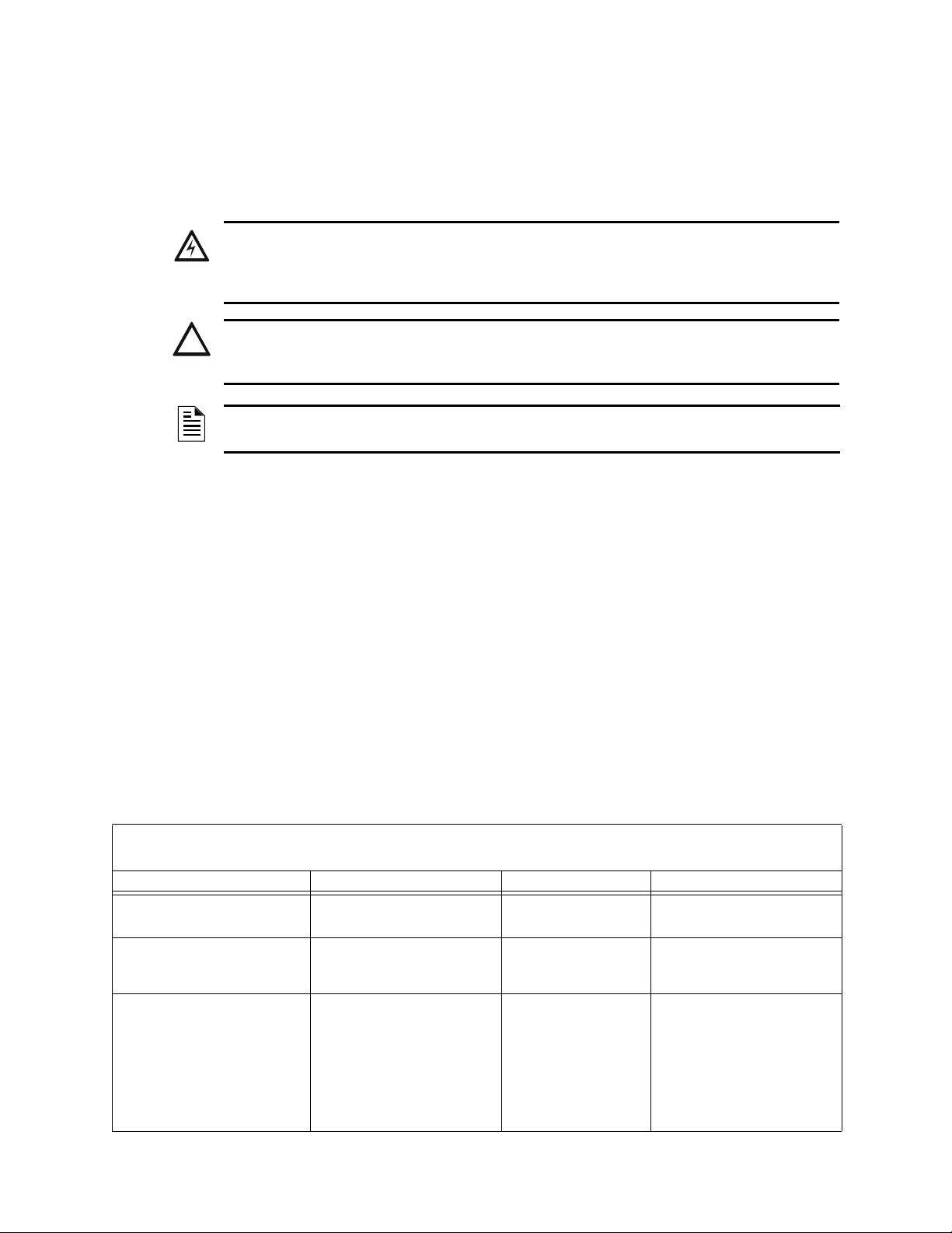
The following graphics appear in the manual to indicate a caution, a warning, or a note.
WARNING:
INFORMATION ABOUT PROCEDURES THAT COULD CAUSE IRREVERSIBLE DAMAGE TO
THE CONTROL PANEL, IRREVERSIBLE LOSS OF PROGRAMMING DATA OR PERSONAL
INJURY.
CAUTION:
INFORMATION ABOUT PROCEDURES THAT COULD CAUSE PROGRAMMING ERRORS,
RUNTIME ERRORS, OR EQUIPMENT DAMAGE.
NOTE: Information that highlights an important part of the preceding or subsequent text or
illustration.
1.2 UL 864 Compliance
1.2.1 Products Subject to AHJ Approval
This product has been certified to comply with the requirements in the Standard for Control Units
and Accessories for Fire Alarm Systems, UL 864 9th Edition.
A complete listing identifying which products have
or have not received UL 864 9th Edition
certification is located in the installation manual of this fire alarm system. These products may only
be used in retrofit applications. Operation of the NFS2-3030 with products not tested for UL 864
9th Edition has not been evaluated and may not comply with NFPA 72 and/or UL 864. These
applications will require the approval of the local Authority Having Jurisdiction (AHJ).
1.2.2 Programming Features Subject to AHJ Approval
This product incorporates field-programmable software. The features and/or options listed below
must be approved by the local AHJ.
This product incorporates field-programmable software. In order for the product to comply with the requirements in the Standard for Control
Units and Accessories for Fire Alarm Systems, UL 864, certain programming features or options must be limited to specific values or not
Program Feature or Option Permitted in UL 864? (Y/N) Possible Settings Settings Permitted in UL 864
IP downloads over a local area network
(LAN) or the internet (Wide Area Network WAN)
Releasing: Abort Switch Yes NYC
Detector Programming: Supervisory Type
Codes
No Yes
Yes SUP L(DUCTI)
used at all as indicated below.
No
Timed
AHJ
ULI
IRI
SUP T(DUCTI)
SUP T(DUCTP)
SUP L(DUCTP)
SUP L(ION)
SUP T(ION)
SUP L(PHOTO)
SUP T(PHOTO)
SUP L(LASER)
SUP T(LASER)
P/CO (P SUP)
No
ULI
IRI
SUP L(DUCTI)
SUP T(DUCTI)
SUP L(DUCTP)
SUP T(DUCTP)
8 NFS2-3030 Programming Manual — P/N 52545:K1 03/20/2012

Related Documents General Information
This product incorporates field-programmable software. In order for the product to comply with the requirements in the Standard for Control
Units and Accessories for Fire Alarm Systems, UL 864, certain programming features or options must be limited to specific values or not
Program Feature or Option Permitted in UL 864? (Y/N) Possible Settings Settings Permitted in UL 864
AC Fail Delay Timer Yes None, or 1-12 hours 1-3 hours
Regional Settings Yes Singapore
FMM-4-20 Event Settings Yes No Event
used at all as indicated below.
Chicago
Australia
China
Trouble
Fire
Supervisory
Security
Nonfire
Critical Process
Chicago
No Event
Trouble
Supervisory
Security
Nonfire
Critical Process
1.3 Related Documents
The table below provides a list of document sources (manuals) containing additional information
regarding the NFS2-3030 and optional peripherals. The NOTIFIER document (DOC-NOT) chart
provides the current document revision. A copy of this document is included in every NOTIFIER
shipment.
Compatible Conventional Devices (Non-addressable) Document Number
Device Compatibility Document 15378
Fire Alarm Control Panel (FACP) and Main Power Supply Installation Document Number
NFS2-3030 Installation, Operations, and Programming Manuals 52544, 52545, 52546
AMPS-24/E Addressable Power Supply Manual 51907
SLC Wiring Manual 51253
Note: For individual SLC Devices
*Note: Also documents some retrofit equipment manufactured under UL 8th edition
Audio System and Component Installation Document Number
DVC Digital Voice Command Manual 52411
DAL Devices Reference Document 52410
DVC-RPU Manual 50107425-001
DVC-RPU UL Listing Document 50107424-001
DAA2 and DAX Series Digital Audio Amplifiers 53265
DS-DB Digital Series Distribution Board and Amplifier 53622
AA-Series Audio Amplifier Manual 52526
Heat Dissipation for Cabinets with Audio Products 53645
Off-line Programming Utility Document Number
VeriFire™ Tools CD help file VERIFIRE-TCD
Cabinets & Chassis Document Number
CAB-3/CAB-4 Series Cabinet Installation Document 15330
Battery/Peripherals Enclosure Installation Document 50295
Power Supplies, Auxiliary Power
ACPS-610 Addressable Power Supply Manual 53018
ACPS-2406 Installation Manual 51304
APS2-6R Auxiliary Power Supply 53232
CHG-120 Battery Charger Manual 50641
FCPS-24 Field Charger/Power Supply Manual 50059
, refer to the SLC Wiring Manual
Supplies
& Battery Chargers Document Number
Table 1.1 Related Documents (1 of 2)
NFS2-3030 Programming Manual — P/N 52545:K1 03/20/2012 9

General Information Related Documents
FCPS-24S6/S8 Field Charger/Power Supply Manual 51977
Networking Document Number
Noti•Fire•Net Manual, Network Version 4.0 & Higher 51584
*Note: Also documents some retrofit equipment manufactured under UL 8th edition
High Speed Noti•Fire•Net Manual 54013
on
NCM-W/F Installati
HS-NCM High Speed Network Communications Module Installation Document 54014
NCS ONYX™ Network Control Station, Network Version 4.0 & Higher Manual 51658
NCA-2 Network Control Annunciator Manual 52482
NCA Network Control Annunciator Manual 51482
System Components Document Number
Annunciator Control System Manual 15842
Annunciator Fixed Module Manual 15048
ACM-8R Annunciator Control Module Manual 15342
LCD-80 Manual 15037
LCD2-80 Liquid Crystal Display 53242
LCD-160 Manual 51850
LDM Series Lamp Driver Annunciator Manual 15885
SCS Smoke Control Manual (Smoke and HV
RPT-485W/RPT-485WF EIA-485 Annunciator Loop Repeater 15640
DPI-232 Manual 51499
TM-4 Installation Document (Reverse Polarity
UDACT Manual (Universal Digital Alarm Communicator/Transmitter) 50050
UDACT-2 Manual (Universal Digital Alarm Communicator/Transmitter) 54089
ACT-1 Installation Document 52527
ACT-2 Installation Document 51118
ACT-4 Installation Document 53431
ACT-25 Installation Document 53432
ACT-70 Installation Document 53240
FireVoice 25/50 Series 52290
RM-1 Series Remote Microphone Installation Document 51138
RA100Z Remote LED Annunciator Document I56-0508
RFX Wireless Interface Manual 51012
UZC-256 Universal Zone Coder Manual 15216
UZC-256 Programming Manual 15976
XP Transponder Manual 15888
XP10-M Ten Input Monitor Module Installation Document I56-1803
XP5 Series Manual 50786
XP6-C Supervised Control Module Installation Document I56-1805
XP6-MA Six Zone Interface Mod
XP6-R Six Relay Control Module Installation Document I56-1804
XPIQ Audio Transponder Manual 51013
Document 51533
Control Station) Manual 15712
AC
Transmitter) 51490
ule Installation Document I56-1806
Table 1.1 Related Documents (2 of 2)
10 NFS2-3030 Programming Manual — P/N 52545:K1 03/20/2012

Introduction to the Control Panel General Information
1.4 Introduction to the Control Panel
The NFS2-3030 is an intelligent Fire Alarm Control Panel (FACP) with features suitable for most
applications.
There are two basic configuration options for the NFS2-3030. It
• a front display/keypad, which allows programming and viewing options at the panel, or
• no display/keypad.
This manual gives programming instructions using the front display/keypad.
Displayless Mode
When there is no keypad/display
Tools programming is required. The displayless panel has four buttons on its circuit board that are
service-level switches for local operation should it become necessary. They are the only buttons,
and are clearly marked with ACK for Acknowledge, SIGSIL for Signal Silence, SYSRST for
System Reset, and LAMP TEST. These buttons are mainly for installer use: the operator should
utilize a remote annunciator for these functions, if possible. The status indicator LEDs on the
circuit board are the same as on the display/keypad; refer to the NFS2-3030 Operating Manual for
LED descriptions.
Refer to VeriFire™ Tools for information on programming without an NFS2-3030 display/keypad.
A PC is required when using V
Canadian applications must conform to ULC requirement
to the Canadian Applications appendix in this panel’s installation manual.
1.4.1 Features
Programming features include the following:
can be ordered with:
at the panel, it is controlled by remote annunciators. VeriFire™
eriFire™
Tools.
s for displays and network control. Refer
• Ease of use - Field program the control panel without special software skills.
• Local programming - program directly from the control panel keypad to reduce installation
time.
•
PC programming - input long data entry programming information on a PC; transfer
programmi
• Autoprogram option - automatically detect newly installed, addressable devices, allowing
quicker in
• Security - use passwords to control access to
• Large display option - 640 character screen, 16 lines x
ng data between a PC and the control panel.
stallation.
the control panel and protect programming.
40 characters
1.5 Navigating Menu and Programming Screens
The Main Menu (refer to Figure 2.1) leads to screens with various menu and programming options.
Choices may be made from the menu screens by pressing the soft key closest to the menu option.
Appendix A, “Menu Hierarchy” gives the programming menu hierarchy; refer to this appendix for
an overall view of the layout of the screens.
Field information may be added/modified using the keyboard and special function keys.
Arrow keys on the keyboard can be used to navigate be
keys to select the fields.
Scrolling through a list of selections in a screen field can
pressing the associated soft key, or by pressing the Next Selection/Previous Selection special
function keys on the Display/Keypad.
tween fields on a screen if there are no soft
be performed either by repeatedly
Pressing a BACK
the information entered.
NFS2-3030 Programming Manual — P/N 52545:K1 03/20/2012 11
soft key on a screen returns the programmer to the previous screen without saving

General Information Basic Procedure
Pressing an ACCEPT soft key will save the information entered on the screen. It may also return to
the previous screen and/or perform other functions as described in the soft key section for each
screen.
When the FACP can not read an address (that is, if the
does not exist) it will display an error screen for several seconds, then return to the screen where the
address was entered. The user must check his input and investigate the state of the point.
1.6 Basic Procedure
For initial programming of the panel, or for major changes and additions, the following basic
procedure is recommended to prevent errors resulting in reprogramming and wasted time.
• Use work sheets to record the exact information for every detector, module, annunciator point
and software zone
systems, pay close attention to AMG annunciator point commands. The panel program may
also be created using VeriFire™ Tools and downloaded to the panel after assembly and powerup.
• Assemble and apply power to the control panel as described in this panel’s installation manual.
system boards must be physically installed.
All
• Read this manual before programming.
• Enter/change master and user passwords.
• Enter panel and network parameters.
• Program all devices and thoroughly test the entire system. The W
test devices and their programming.
• Make a hard-copy record of the program on the printer.
• Save the program by uploading it using VeriFire™ Tools.
point entered on the screen for processing
in the system. Pay close attention to the Software Type IDs. For voice
alk Test feature can be used to
1.7 Getting Started
Once the system has been physically installed, programming may begin. The user may program at
any time except while there is an unacknowledged alarm present.
To ensure security, passwords should be entered at this time to rep
1.7.1 Password Change
The NFS2-3030 has two password levels; master and user. There is one master password, which
grants access to all system programming. There are nine user passwords, each of which may be
assigned access to the programming change menus, the alter status menus, or both. A user
password does not give access to or allow change to any password parameters, not even its own.
Only the master password will allow access to password change screens.
The panel arrives with factory default settings o
for one user password.
Follow the steps below to change the
1. Press PROGR
2. Using the keyboard, enter eight
3. Press the ACCEP
4. Press the PANEL PR
5. Press the MORE
6. Press the PASSW
lace the factory default settings.
f 00000000 for the master password, and 11111111
factory settings:
AM/ALTER STATUS at the Main Menu screen.
zeroes (00000000) after ENTER PASSWORD.
T soft key.
OGRAM MENU soft key.
soft key.
ORD CHANGE soft key.
12 NFS2-3030 Programming Manual — P/N 52545:K1 03/20/2012
Getting Started General Information
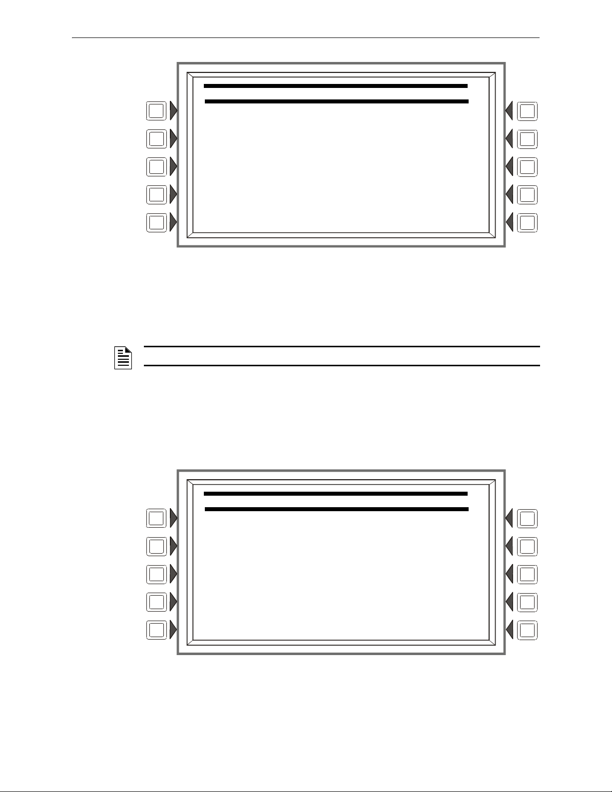
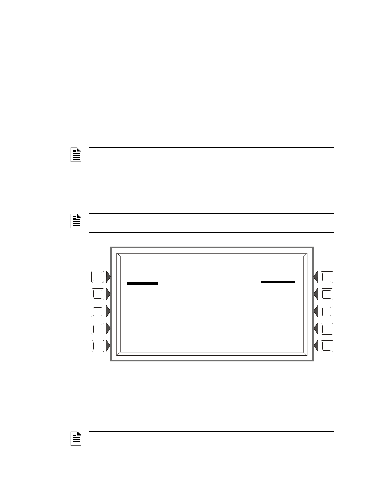
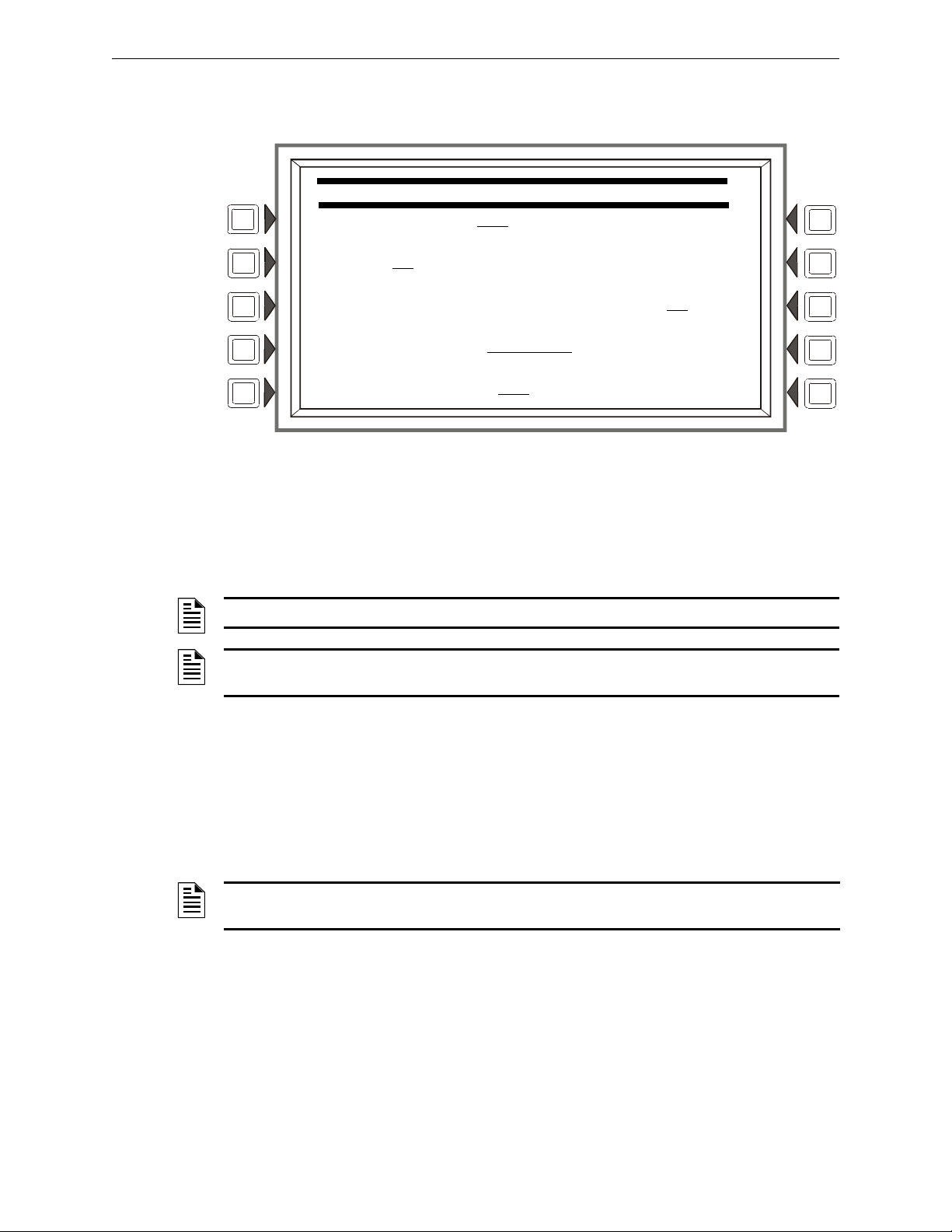
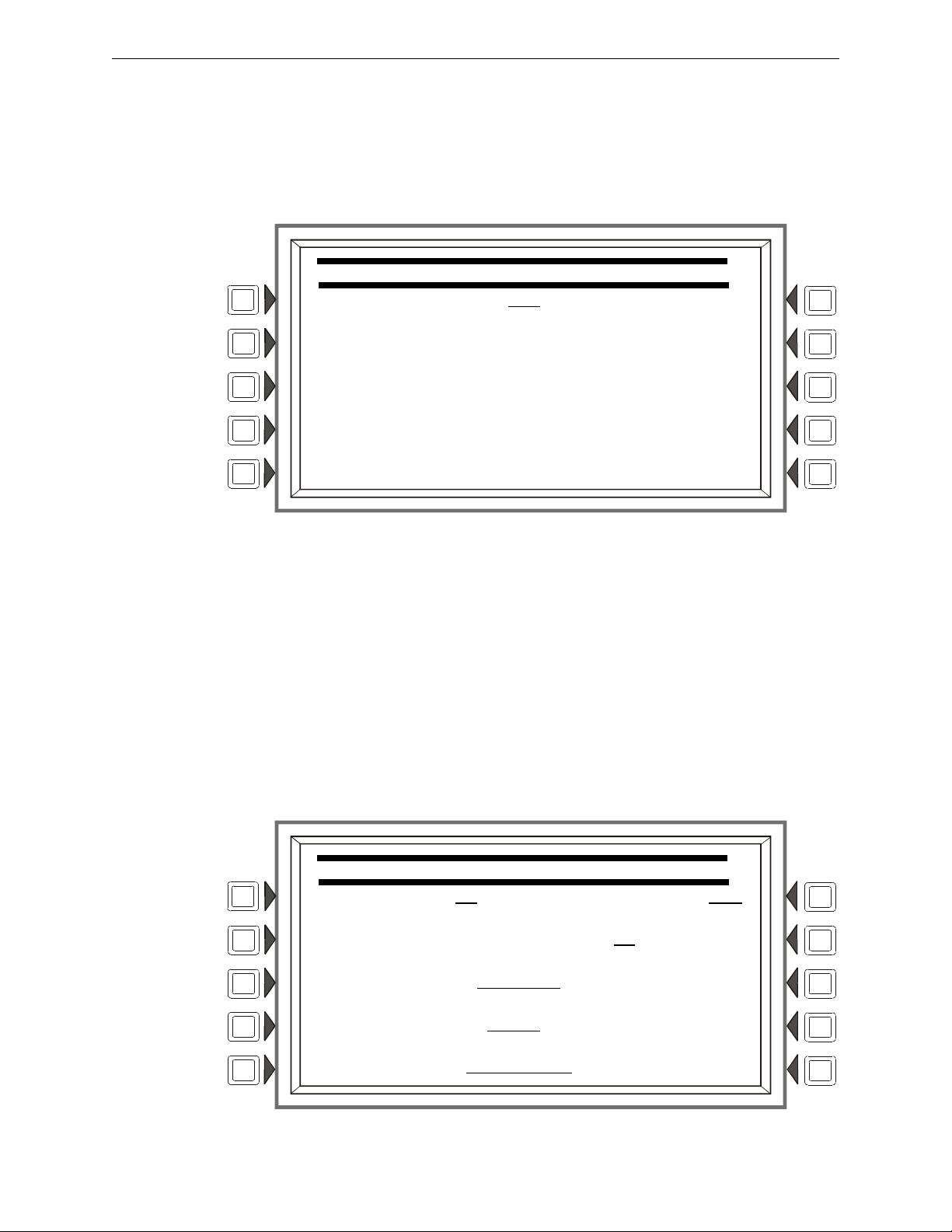
CHANGE PASSWORD
MASTER PASSWORD
USER PASSWORD
BACK
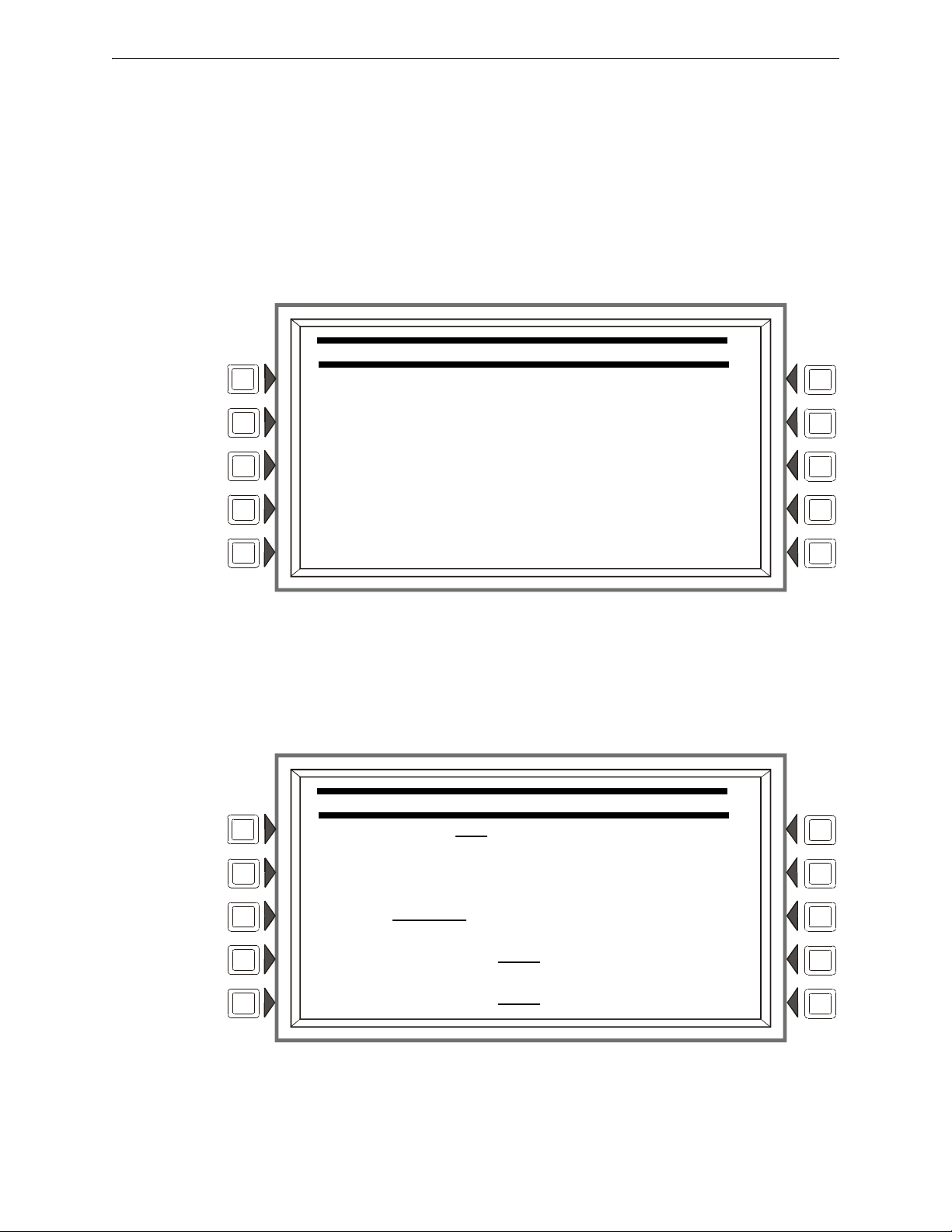
CHANGE MASTER PASSWORD
ENTER PASSWORD ********
RE-ENTER PASSWORD ********
BACK
Figure 1.1 Change Password Screen
Soft Keys
MASTER PASSWORD - Press to change the master password
USER PASSWORD - Press to change the user password.
NOTE: Only a master can change another password.
Master Password
Press the MASTER PASSWORD Soft Key to display the following screen. Enter a new password
that will replace the factory default password: there can be up to eight alphanumeric characters.
Press the enter key on the keyboard. RE-
verification. Press enter to save the new password.
ENTER PASSWORD will appear. Reenter the password for
NFS2-3030 Programming Manual — P/N 52545:K1 03/20/2012 13
Figure 1.2 Change Master Password Screen
General Information Getting Started
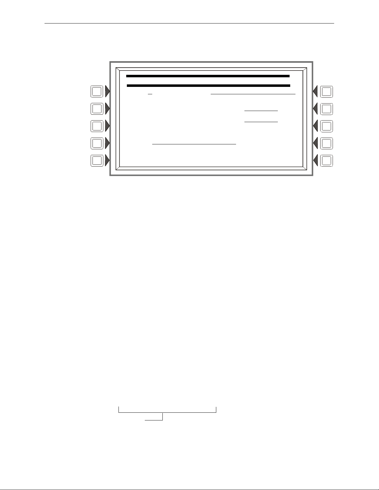
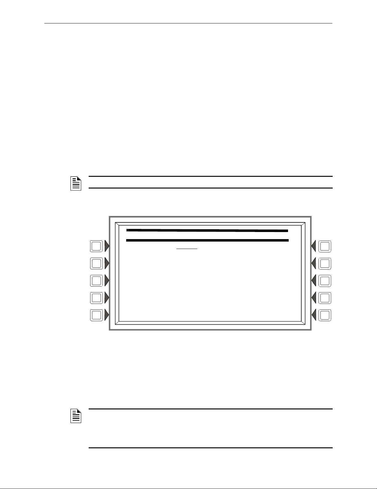
CHANGE USER PASSWORD
USER:1 REFERENCE:JOHN
ENTER PASSWORD ********
RE-ENTER PASSWORD ********
MODE: PROGRAM/ALTER STATUS ACCEPT
BACK
INVALID PASSWORD:
9066-21FS-7D78-5FA4-6163
Code
User Password
Press the USER PASSWORD soft key to display the following screen.
Figure 1.3 Change User Password Screen
Soft Keys
USER: Press this
pressed, the rest of the display will update to reflect information for each new record. Stop at the
password number that requires entering.
MODE: Press this
• PROGRAM/ALTER STATUS Gives
Menu.
• ALTER STATUS Gives access to the Alter Status Menu
• NONE Gives no access.
EFERENCE: Pres
R
user. Press the enter key on the display/keyboard to enter the information.
ENTER PASSWORD - Press to enter
then press enter. RE-ENTER PASSWORD will appear. Retype the password for verification.
ACCEPT: After entering
soft key to save all the password information.
Incorrect or Forgotten Password
If a password is entered incorrectly, the panel will respond by displaying an INVAL
PASSWORD message and a code. The programmer may hit the escape key and re-enter the
password correctly. However, if the password has been forgotten, record the code and contact
NOTIFIER. After proper authentication, the master password can be determined by deciphering the
14 NFS2-3030 Programming Manual — P/N 52545:K1 03/20/2012
code. An example of the message that would appear on the display follows:
soft key to scroll through the nine user password numbers. When this key is
soft key to select the user’s level of access. Levels are as follows:
access to the Program Change Menu and Alter Status
s this key to enter a maximum 20-character alphanumeric label that identifies the
a new password. Enter up to eight alphanumeric characters,
all password information and retyping the password at the prompt, press this
ID
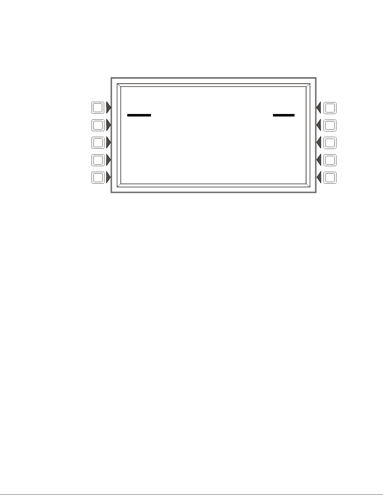
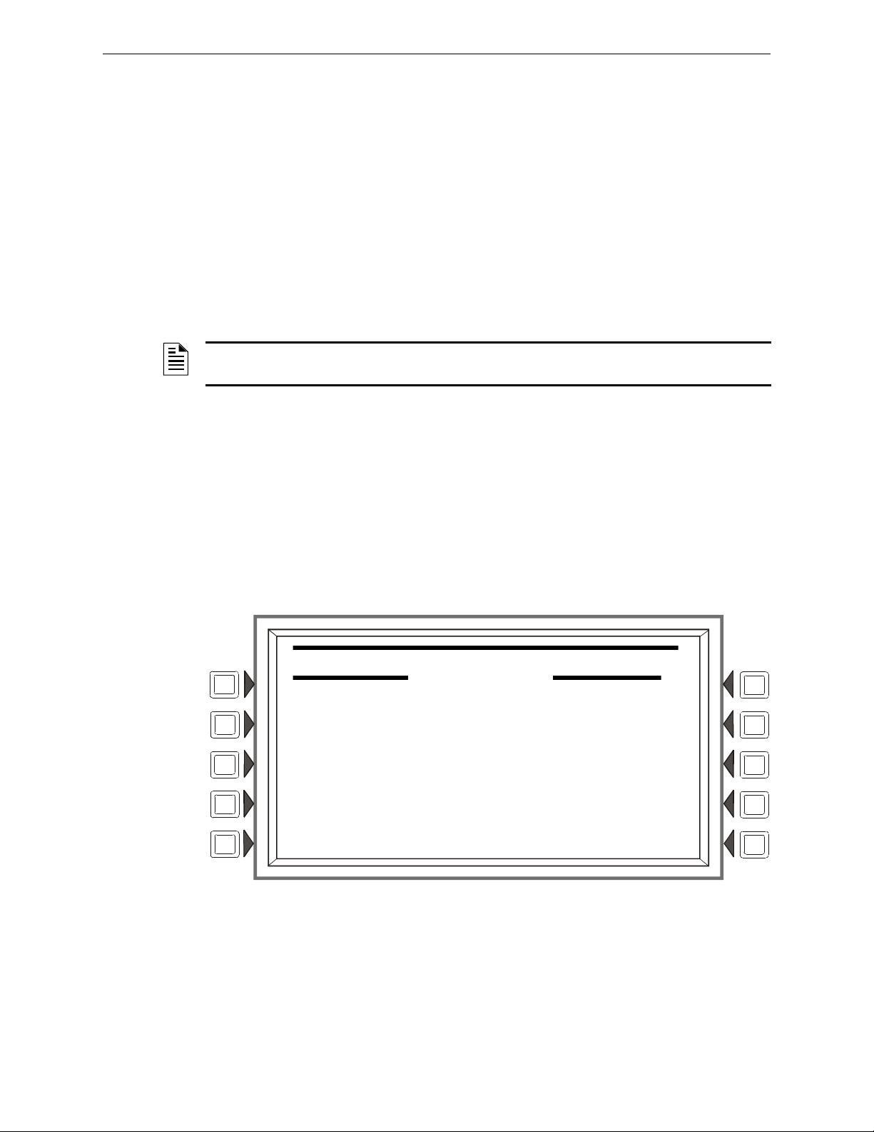
Section 2: Main Menu
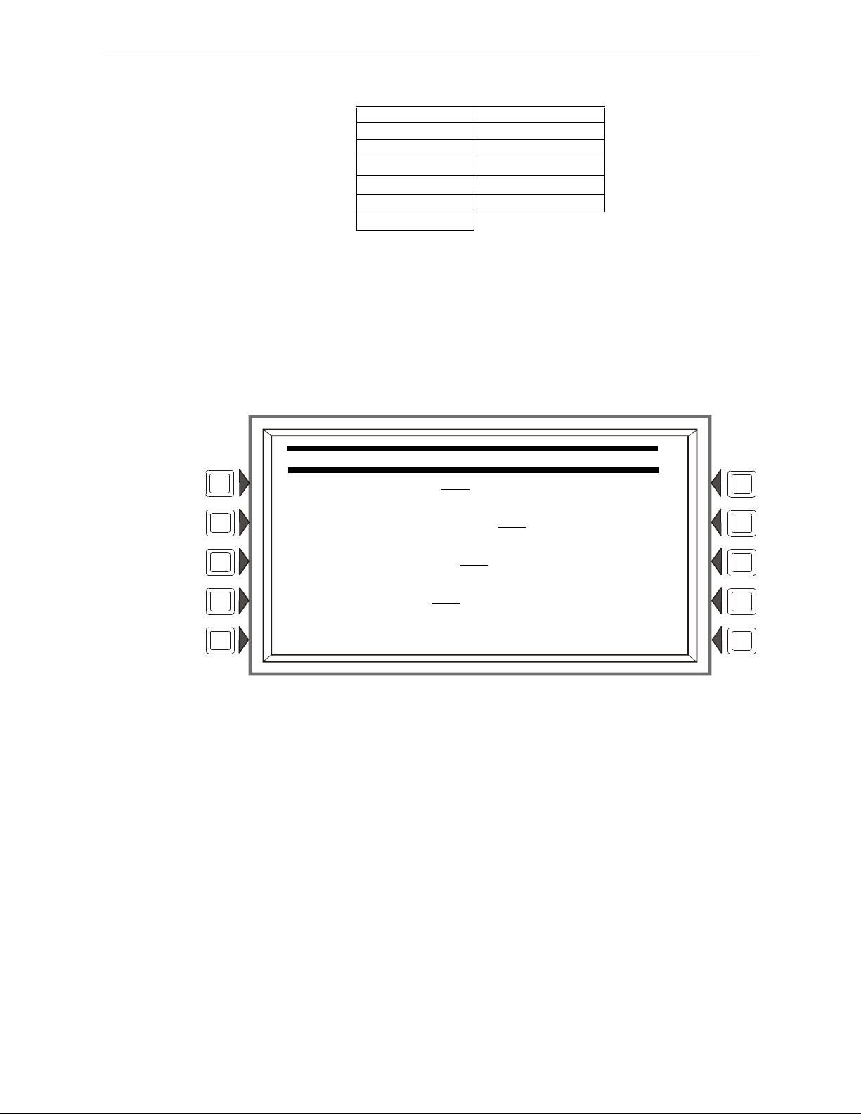
LAKEVIEW GENERAL HOSPITAL
SYSTEM NORMAL
11:58:45A TUE JAN 25, 2011
EVENT COUNTS DISPLAY READ STATUS
PROGRAM/ALTER STATUS
MULTIPLE EVENT LIST PRINTER FUNCTIONS
HISTORY DISPLAY BACK
The Main Menu screen is the means by which the programmer can access displays, history
information, printing and programming menus. This screen is accessible from the System Normal
Screen, and from most other screens by pressing the BACK soft key until it displays.
Figure 2.1 Main Menu Screen
Soft Keys
to
Pressing the soft keys brings the user
the screens described below.
2.1 Event Counts Display
Pressing the EVENT COUNTS DISPLAY soft key on the Main Menu brings up the EVENT
COUNTS screen. This screen will automatically display if an off-normal event requiring
acknowledgement occurs. The display consists of current counts of off-normal events in six
categories: the counts include both acknowledged and unacknowledged events.
Refer to this panel’s operations manual for an illustration and description of the Event Counts
Display
.
2.2 Multiple Event List
Pressing the Multiple Event List soft key shows off-normal events simultaneously in groups of
eight. It displays automatically for off-normal events when the Canada event order has been
selected. Refer to Event Ordering in “Panel Settings” on page 21 for information on display order.
Refer to this panel’s operations manual for an illustration and description of the Multiple Event
List.
2.3 History Display (History Select Screen)
NFS2-3030 Programming Manual — P/N 52545:K1 03/20/2012 15
The History Select screen allows the user to select a type of history file to view, and to set time/date
or point range viewing parameters.
Refer to this panel’s operations manual for an illustration and description of History Display.

Main Menu Read Status
2.4 Read Status
Pressing the Read Status soft key brings up screens to view the present status of points, zones, and other
system information. Refer to this panel’s operations manual for a full description of Read Status.
2.5 Program/Alter Status
Pressing the Program/Alter Status soft key brings up screens for panel programming, point
programming, autoprogramming, clear programming, altering the status of points, walk test, and
other information. Refer to Sections 3, and 4 for a full description of Program/Alter Status.
2.6 Printer Functions
Pressing the Printer Functions soft key brings up screens to print reports. Refer to this panel’s
operations manual for a description of Printer Functions. This key will appear only if a printer
operation has been selected. Refer to “Supervision” on page 35 for selection information.
16 NFS2-3030 Programming Manual — P/N 52545:K1 03/20/2012
Section 3: Program
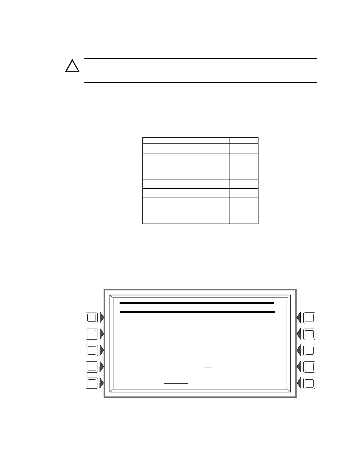
LAKEVIEW GENERAL HOSPITAL
SYSTEM NORMAL
10:22:34A TUE JAN 25, 2011
PROGRAM/ALTER STATUS
ALTER STATUS MENU DELETE PROGRAM MENU
AUTOPROGRAM MENU
PANEL PROGRAM MENU
POINT PROGRAM MENU BACK
3.1 General Information
The NFS2-3030 operates with two levels of programming: Program, and Alter Status.
Program level allows change to the essential control pane
l functions such as point functions, system
functions, and passwords. Program level change requires the master password, or a user password
that allows access to the Program level. All password information can be changed with a master
password only.
Alter Status level allows change to operating parame
ters, such as detector sensitivity, or time/date,
or Walk Test. The master password, or a user password that allows access to the Alter Status level,
is required.
NOTE: All events except troubles are annunciated during programming. When an annunciated
event occurs, the panel will automatically exit the programming screen and the Event Counts
menu screen will appear.
To access the Program level, press the Program/Alter St
atus soft key on the Main Menu and at the
prompt enter a master password, or a user password that allows access to the Program level. The
following screen will display.
NOTE: No program menus will display if a user password is entered that has access to Alter
Status level only: the Alter Status menu will be the sole menu choice.
Figure 3.1 Program/Alter Status Screen
rog
NFS2-3030 Programming Manual — P/N 52545:K1 03/20/2012 17
Press a soft key with the word “p
When programming the panel for the first time, press
which brings up the Delete Program Menu screen (Refer to Figure 3.55). Press the CLEA
PROGRAMMING butto
n, then ACCEPT, to ensure that the panel is set to defaults and clear of
programs.
NOTE: Clearing all programs is not necessary when initial programming with a database
downloaded from VeriFire™ Tools.
ram” in its menu to bring up the associated program menu.
the DELETE PROGRAM MENU soft key,
R ALL
Program Panel Program
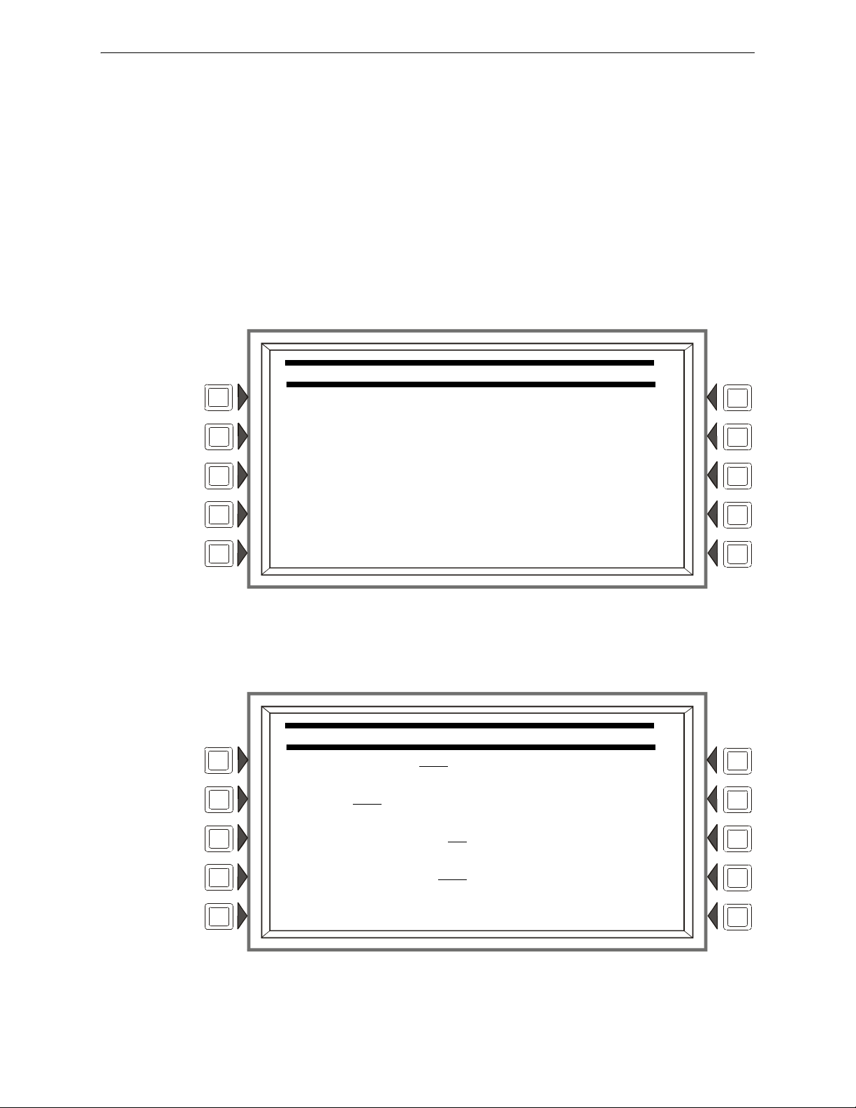
PANEL PROGRAM MENU
NETWORK PARAMETERS LCD DISPLAY
NETWORK MAPPING ACS PROGRAMMING
PANEL SETTINGS SUPERVISION
PANEL TIMERS MORE
BACK
NETWORK PROGRAMMING
NODE NUMBER: 000
NODE LABEL:
LAKEVIEW GENERAL HOSPITAL
STYLE: STYLE 7
IP ACCESS
CH A. THRESHOLD: HIGH ACCEPT
CH B. THRESHOLD: LOW BACK
The logical sequence for initial programming is to program the panel parameters first, then to
program the individual points through autoprogramming and/or point programming.
3.2 Panel Program
Panel programming provides the means to change settings for the panel system as a whole, as well
to address and program annunciator points.
3.2.1 Panel Program Menu (1)
Press the Panel Program Menu for the following choices.
Figure 3.2 Panel Program Menu 1 Screen
3.2.2 Network Parameters
Press the Network Parameters soft key on Panel Program Menu 1 to bring up the following screen.
If the panel will operate as a standalone unit and not part of a network, the node label is the only
field that needs to be entered: it is the label that appears as part of the System Normal message.
18 NFS2-3030 Programming Manual — P/N 52545:K1 03/20/2012
Figure 3.3 Network Programming Screen
Panel Program Program
IP ACCESS
IP ACCESS: ON
ACCEPT
BACK
Soft Keys
NODE NUMBER: Enter t
he network node number of this panel. For standalone NFS2-3030, the
network node number will be 000. A valid network node number range is 1-240. Once the soft key
has been pressed, the number may be typed in from the keypad, or the Next/Previous Selection spe-
gle th
cial function key on the keypad may be used to tog
rough online node numbers. The network
node number may be viewed by pressing the Lamp Test special function key longer than five seconds. (Refer to Section 5.1, “Version Information”, on page 86.) Default: 000
NODE LABEL: Ente
r the network node label for this panel. This is the label that appears in the
System Normal message. Default: <blank>
STYLE: Select the wiring style as
CHANNEL A THRES
HOLD, CHANNEL B THRESHOLD: Enter HIGH or LOW, for high or low
4 or 7. Default: style 4
threshold setting for channel A or B on the network communications module. Default: HIGH
IP ACCESS: Press this soft key to bring up the IP ACCESS screen.
A
CCEPT: Press this
soft key to save the information entered on this screen.
IP ACCESS Screen
NOTE: Use of the IP ACCESS feature is subject to the approval of the local AHJ.
This screen allows the programmer to set the IP Access. This setting allows the disabling/enabling
of commands, downloads and programming from the Wide Area Network (WAN).
Figure 3.4 IP Access Screen
Soft Keys
IP ACCESS: Press th
e soft key to scroll through the choices. Press ACCEPT at the desired setting.
Settings are:
ON - IP commands, downloads and programming are allowed.
NFS2-3030 Programming Manual — P/N 52545:K1 03/20/2012 19
OFF - IP commands, downloads and programming are NOT allowed. (default)
TIMED - IP commands, downloads and programming are allowed for a two-hour period, after
which the setting will revert to OFF.
NOTE: Enabling IP ACCESS allows downloads over a local area network (LAN) or the internet
(Wide Area Network - WAN) using VeriFire™ Tools through the Noti•Fire•Net™ Web Server
(NWS), or a wide-area enabled NCS through a PC version of Noti•Fire•Net™ Gateway.
Always verify system operation after programming changes are made in this manner.
Program Panel Program
NETWORK MAPPING
SCREEN 01 OF 15
001:OFFLINE / 002:OFFLINE /
003:ONLINE /MAPPED 004:OFFLINE /
005:OFFLINE / 006:OFFLINE /
007:OFFLINE / 008:OFFLINE /
009:ONLINE /MAPPED 010:OFFLINE /
011:OFFLINE / 012:OFFLINE /
013:OFFLINE / 014:OFFLINE /
015:OFFLINE / 016:OFFLINE /
AUTO PROGRAM ACCEPT
NEXT BACK
Main menu
Program/alter status menu
Panel program menu
Network mapping
3.2.3 Network Mapping
The Network Mapping softkey is only available if the Network Display Mode option is enabled.
Pressing the softkey will display the following screen. Refer to Appendix J, “Network Display
Mode”, on page 152.
There are 15 of these screens covering nodes 1 through 24
0. Each screen will have 16 nodes on it.
The up and down arrow keys are used to select which node to edit. When a field is selected, the
NEXT SELECTION/PREVIOUS SELECTION keys will toggle between OFFLINE/ONLINE,
MAPPED/UNMAPPED.
• OFFLINE - The node
• ONLINE - The
• MAPPED - Events
• UNMAPPED (blank) - Events are ignored
NOTE: The NFS2-3030 can be programmed to monitor events and initiate drill on one (1) additional fire
panel and up to four (4) DVCs.
NEXT navigates to the next screen in the sequence. The las
is not communicating on the network.
node is communicating on the network.
are annunciated by the NFS2-3030.
by the NFS2-3030.
t screen will not have a NEXT key.
BACK will go to the preceding screen in the sequence or to the Node Programming menu if the
current screen is the first one in the 15-screen sequence. ACCEPT implements any changes that
have been made up to this point and returns the user to the Node Programming menu. AUTO
PROGRAM will consult the internal map of which nodes are on the network and automatically set
all 240 Nodes according to the map, regardless of which screen is being shown. The results will not
be saved to flash until the ACCEPT key is pressed.
20 NFS2-3030 Programming Manual — P/N 52545:K1 03/20/2012
Figure 3.5 Program Menu: Network Mapping
Panel Program Program
PANEL SETTINGS
LOCAL CONTROL: YES
REMINDER MENU
PIEZO: ON
MORE
PROPRIETARY SUPERVISING STATION: NO
EVENT ORDERING: USA ACCEPT
DISPLAY ADDRESS: YES
BACK
3.2.4 Panel Settings
Press the Panel Settings soft key on the Panel Program Menu 1 screen to choose panel settings.
Figure 3.6 Panel Settings (1) Screen
Soft Keys
LOCAL CONTROL
: Press this soft key to toggle between YES and NO. This option disables (NO) or
enables (YES) local panel control of the Signal Silence, System Reset, and Drill Fixed Function keys, as
well as SIGNAL SILENCE, SYSTEM RESET, and ACKNOWLEDGE soft keys. A setting of NO (disable)
turns the panel piezo sounder off, overriding the next field if PIEZO is set to ON. Default: YES
NOTE: A setting of NO (disable) will disable key switch operation.
NOTE: ACS devices programmed for acknowledge, signal silence, system reset and drill are not affected
by this setting: these commands will still function at the devices if LOCAL CONTROL is set to NO.
PIEZO:Press this
soft key to toggle between OFF and ON. This option enables (ON) or disables
(OFF) the panel piezo from sounding when alarms or troubles occur. A setting of ON is overridden
if LOCAL CONTROL is set to NO. Default: ON
PROPRIETARY SUPER
VISING STATION:Press this soft key to enable (YES) or disable (NO)
Local Receive mode. When enabled, events and the clearing of events must be handled one at a
time: each must be acknowledged. Latching events require a system reset. The panel will override a
setting of YES if the Node Number is greater than zero. Default: NO
NOTE: Proprietary Supervising Station does not support standalone mode (direct connect) with a
Digital Voice Command.
NFS2-3030 Programming Manual — P/N 52545:K1 03/20/2012 21
This order is applied to events shown in the Multiple Events List screen. Default: USA
EVENT O
RDERING: Press this soft key to toggle between US
A and CANADA ordering priorities.
Program Panel Program
PANEL SETTINGS
LCM LOCAL MODE: YES REGIONAL SETTINGS
POWER MANAGEMENT MODE:OFF
DCC PARTICIPATION: NO MORE
RAPID ALL CALL: NO ACCEPT
DEFAULT SETTINGS BACK
USA Event Order Canada Event Order
Fire Fire
Security Supervisory
Supervisory Trouble
Trouble Prealarm
Prealarm Disabled
Disabled
Table 3.1 Event Ordering
DISPLAY ADDR
ESS: Press this soft key to toggle between YES and NO. Choose YES to display
all point address information at the top of event screens and in printouts. Choose NO to suppress
address information display and printing. Default: YES
REMINDER MENU:
ACCEPT: Press this
MORE: Press this
Press this soft key to bring up the Reminder Menu screen.
soft key to save the information entered on this screen.
key to progress to the second Panel Settings screen.
Figure 3.7 Panel Settings (2) Screen
Soft Keys
LCM LOCAL MO
DE: Press this soft key to toggle between YES and NO. Enter YES to enable all
SLCs to participate in local mode. When enabled, all LCMs will operate together in a limited
fashion when communication is lost with the NFS2-3030 CPU. Inputs on LCM loops (and
associated LEM loops, if installed) will activate outputs on all loops
• for those inputs and outputs that have been set with point programming to participate in local
mode, an
• when type codes are the same point type: that is, an input with
22 NFS2-3030 Programming Manual — P/N 52545:K1 03/20/2012
output with a fire type code. (Refer to Appendix G, “Type Codes”, on page 138 for point types).
Default: NO
POWER MANAGEMENT MOD
power consumption. In this mode, the number of LEDs that can be turned ON on a particular loop
will be limited. A maximum of 30 input device (monitor modules and detectors) LEDs will be
allowed ON at a time. No output module LEDs will turn ON. When the limit of 30 LEDs is
reached, every time a new LED is turned ON, the oldest LED activation will turn OFF and will poll
in red rather than the usual green. Default:OFF
d
a fire type code will activate an
E: Select ON to invoke the power management mode to conserve
Panel Program Program
!
PANEL SETTINGS
SOUNDER BASE SETUP MORE
NETWORK DISPLAY MODE:ON ACCEPT
DRILL MODE:CUSTOM
BACK
DCC PARTICIPATION: Press this key to program the panel for DCC (Display and Control Center)
participation. This network function ensures that one location at a time is in command of the
Acknowledge, System Reset, Signal Silence and Drill functions. Default: NO
CAUTION:
ON SYSTEMS UTILIZING THE DCC FUNCTION, ALL LOCATIONS THAT CAN PARTICIPATE IN
DCC SHOULD BE SET TO YES.
RAPID ALL C
ALL: Set YES to invoke Rapid All Call for XP Series transponder modules. For use
when retrofitting an AM-2020/AFP-1010 system that has XPP modules used for audio operation.
This setting causes these modules to activate more quickly. Rapid All Call is used with the
“Speaker” type code. Default:NO
DEFAULT SETT
INGS: Press this soft key to activate default settings for the following:
Program Setting for: Default:
Local Control YES
Piezo ON
Proprietary Supervising Station NO
Event Ordering USA
Display Address YES
LCM Local Mode NO
DCC Participation NO
Power Management OFF
Rapid All Call NO
Table 3.2 Default Settings
REGIONAL SETTI
NGS: Press this soft key to proceed to the Regional Settings screen. Press the
soft key to scroll through the selections. The default is that there are no special regional settings.
Other settings are explained in Appendix I, “Regional Settings”.
MORE: Press this
NFS2-3030 Programming Manual — P/N 52545:K1 03/20/2012 23
key to progress to the third Panel Settings screen.
Figure 3.8 Panel Settings (3) Screen
Program Panel Program
SOUNDER BASE SETUP
CUSTOM TONE SETUP
BACK
CUSTOM TONE SETUP
PULSE ON TIME:0.5
PERIOD:1.0
NUMBER OF PULSES:03
TONE OFF PERIOD:1.5 ACCEPT
BACK
SOUNDER BASE SETUP:Press this soft key to proceed to the SOUNDER BASE SETUP
screen.
NETWORK DISPLAY MODE:Press this softkey to enable Network Display Mode for the fire
panel. Network Display Mode allows the NFS2-3030 to display network events for up to five
mapped network nodes. Refer to “Network Display Mode” on page 152.
DRILL MODE:Press this soft key to select between the STANDARD and CUSTOM drill mode
options. CUSTOM drill mode can be used to activate specific output devices when a drill occurs.
When using CUSTOM drill mode, Special Function Zone 16 must be programmed into the zone
mapping of the devices to be activated during a drill. For more information on Special Zones, refer
to “Zones” on page 131. For more information about DRI
LL MODE, re
fer to Appendix C.2, “Drill
Mode”, on page 119.
MORE: Press this
key to progress to the fourth Panel Settings screen.
Figure 3.9 Sounder Base Setup Screen
CUSTOM TONE SETUP:Press this softkey to proceed to the Custom Tone Setup screen.
24 NFS2-3030 Programming Manual — P/N 52545:K1 03/20/2012
Figure 3.10 Custom Tone Setup Screen

Panel Program Program
Pulse On
Time
Pulse Off
Time
Period
Repeat Tone Pattern
Tone Off Period
Number of Pulses
PANEL SETTINGS
SILENCEABLE WATERFLOW: NO
ACCEPT
BACK
Figure 3.11 Custom Tone Example
PULSE ON TIME:The Pulse On time is the amount of time that the tone will be ON within a
Period. Press this softkey to enter the amount of time in second and fraction of a second increments.
PERIOD:A Period is the length of time designated for a pulse, including Pulse On time and Pulse
Off time. The pulse off time is designated by the amount of time left in a Period after the Pulse On
time has expired. Press this softkey to enter the amount of time in second and fraction of a second
increments.
NUMBER OF PULSES:Press this softkey to enter the number of pulses that will occur before
the Tone Off Period.
TONE OFF PERIOD:The Tone Off Period is the amount of time that the tone will be silent
before running the pulse pattern again. Press this softkey to enter the amount of time in seconds and
fraction of a second increments.
For more information on programming the Intelligent Sounder Base, refer to “Detector Point” on
page 44.
Pressing the MO
NFS2-3030 Programming Manual — P/N 52545:K1 03/20/2012 25
soft key on this Panel Settings screen will display this screen:
RE
Figure 3.12 Panel Settings (4) Screen
Program Panel Program
REMINDER MENU
TROUBLE REMINDER: YES
ACCEPT
BACK
PANEL TIMERS
VERIFY TIME: 30 VERIFY=PREALARM: NO
MAXIMUM VERIFICATION COUNT: 00
AC FAIL DELAY:
2 HOURS MORE
SILENCE INHIBIT:00:00 ACCEPT
AUTO SILENCE: OFF BACK
SILENCEABLE WATERFLOW:If the SILENCEABLE WATERFLOW option is set to NO,
incoming Waterflow events will not be allowed to be silenced. If set to
YES, incoming Waterflow
events can be silenced.
Default:
NO
Reminder Menu
Press the Reminder Menu soft key on the Panel Program Menu 1 screen to set the trouble reminder.
Figure 3.13 Reminder Menu Screen
Soft Keys
TROUBLE REMI
NDER: Press this soft key to toggle between the two possibilities:
YES: Choose this to initiate a daily 11:00AM reminder that there are uncleared troubles in the
system. The reminder will appear on the screen and will sound a piezo (if the piezo is enabled).
NO: Choose this if no reminder is desired. Default: YES
ACCEPT: Press this
soft key to save the information entered on this screen.
3.2.5 Panel Timers (Menu 1)
Press the Panel Timers soft key on the Panel Program Menu 1 screen to display the following
screen.
26 NFS2-3030 Programming Manual — P/N 52545:K1 03/20/2012
Figure 3.14 Panel Timers (Menu 1) Screen

Panel Program Program
Soft Keys
VERIFY TIME: Pr
ess this soft key to set the Alarm Verification timer. Type in a value of 0-60
(seconds), which will delay initiating devices set for Alarm Verification from signaling for the
amount of time entered. If a second alarm occurs while the alarm verification timer is counting, the
timer will stop and the alarm will signal immediately. Default: 30
NOTE: This value may not exceed 30 seconds for ULC installations.
MAXIMUM VERIFICATION COUNT: Press
and enter
a value from 0-20 for a maximum
verification count threshold value that applies to detectors set to participate in Alarm Verification.
A value of zero produces no verification trouble. When the counter exceeds the threshold value
entered, a trouble is generated to the panel. Default: 20
AC FAIL D
ELAY: Press this soft key to set the timing for the time delay from AC failure to when
the trouble is reported. Type in a value of 1-12 (hours), or select NONE. A value of NONE will
cause immediate notification. Default: 8
NOTE: AC FAIL DELAY settings other than 1-3 hours for off-premises notification require the
approval of the local Authority Having Jurisdiction.
The onboard trouble relay (TB3 on the CPU2-3030) will activate and TM-4s will repo
rt according
to this setting.
UDACTs and UDACT-2s are notified immediately of AC failure b
y the panel, regardless of the
panel’s delay setting. Once the UDACT or UDACT-2 receives notification, it operates according to
its own programmed AC Fail Delay reporting schedule.
Example: AC Failure occurs at 1:00 p.m. on a panel with an AC FAIL DE
LAY setting of 8
hours. The UDACT/UDACT-2 is set for notification after 6 hours
Time Event
1:00 p.m. AC Failure. Panel notifies UDACT/UDACT-2. Panel and UDACT/UDACT-2 timers begin
7:00 p.m. UDACT/UDACT-2 reports.
9:00 p.m. TM-4 reports, TB3 trouble relay activates.
countdown to report time.
Table 3.3 AC Fail Delay Example
The AMPS-24, ACPS-610, and ACPS-2406 power supplies must be set to an AC FAIL D
ELAY
value of 0 (zero) when used with this panel.
SILENCE INHI
BIT: Press to enter a value from 0 (disabled) to 5 minutes. This software timer
disables the SIGNAL SILENCE key function for the time entered when a fire alarm occurs. The
timer starts at the first alarm only; it does not restart with each new alarm. Default: 0
AUTO SILENCE: Press to enter a value of OF
F (no Auto Silence Timer), or a value of 10, 15 or
20 minutes. This global software timer functions like pressing the SIGNAL SILENCE key. For
example, if a value of 10 is entered, the control panel will silence all active outputs programmed as
silenceable after ten minutes. Default: 0FF
NOTE: This value must be 20 minutes for ULC installations.
VERIFY=PREALARM: Press
this soft k
ey to enter Yes or No for displaying Prealarm during alarm
verification. Default: NO
NFS2-3030 Programming Manual — P/N 52545:K1 03/20/2012 27
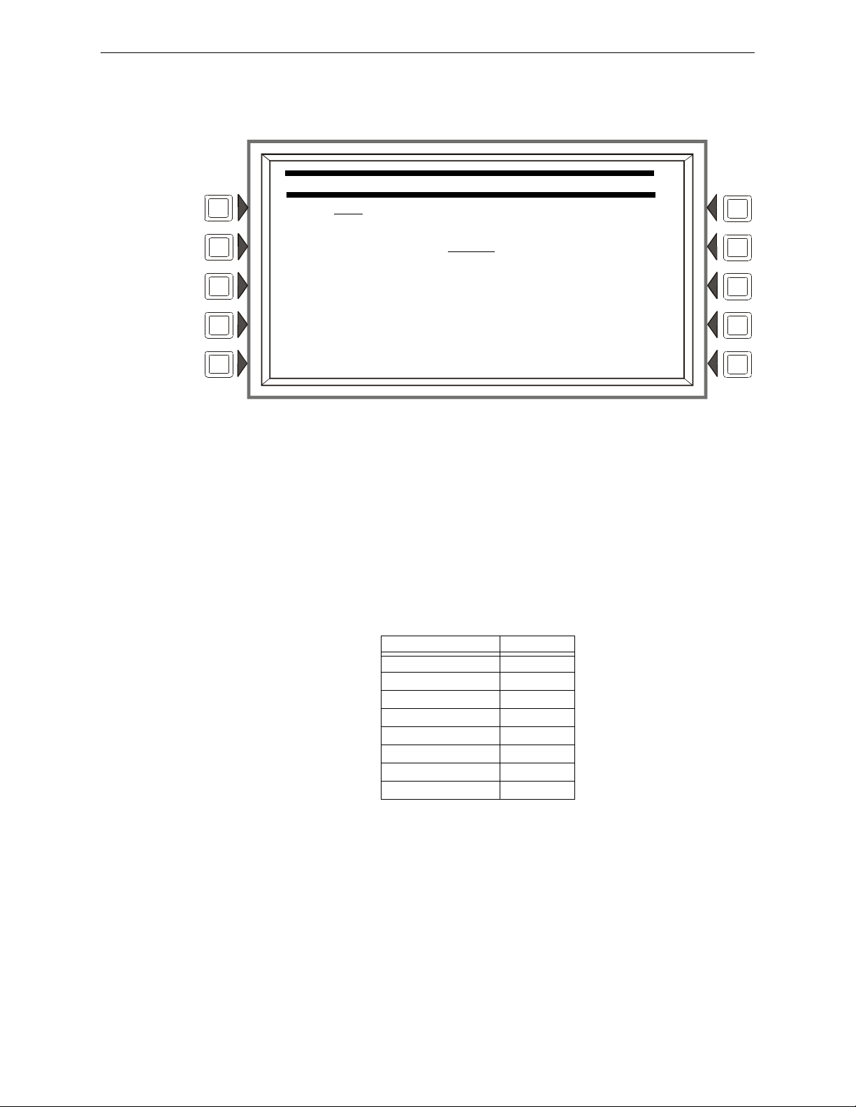
Program Panel Program
PANEL TIMERS
PAS: OFF
PRESIGNAL DELAY: MM:SS
DEFAULT TIMERS
ACCEPT
BACK
3.2.6 Panel Timers (Menu 2)
Press the MORE soft key on the Panel Timers Menu 1 screen to display the following screen.
Figure 3.15 Panel Timers (Menu 2) Screen
Soft Keys
PAS: Press to toggle between the choices of OFF or ON for PAS (Positive Alarm Sequence). Refer
to Appendix C, “Special Zone Outputs” for an explanation of this option. Default: OFF
PRESIGNAL DELAY: Press to enter a
value of 00:00 (OFF) or a value of 1:00 to 3:00 minutes
(in the format MM:SS, where MM= minutes, SS=seconds). This feature initially causes alarm
signals to sound only in specific areas, monitored by qualified personnel. This allows delay of the
alarm for up to 3 minutes after the start of alarm processing. Refer to Appendix C, “Special Zone
Outputs” for further explanation of this option. Default: 3:
D
EFAULT TIMERS: Press this
soft key to activate default settings for the following:
Program setting for: Default:
Verify Time 30 seconds
Max. Verify 20
AC Fail Delay 8 hours
Silence Inhibit 0 (disabled)
Auto Silence Off
Verify=Prealarm No
PAS OFF
Presignal Delay 3 minutes
00
Table 3.4 Default Timers
ACCEPT: Press this
soft key to save the information entered on this screen and return to the
previous screen.
3.2.7 LCD Programming
The LCD Programming screen allows the user to vary the contrast of the display and turn the
backlight on or off.
28 NFS2-3030 Programming Manual — P/N 52545:K1 03/20/2012
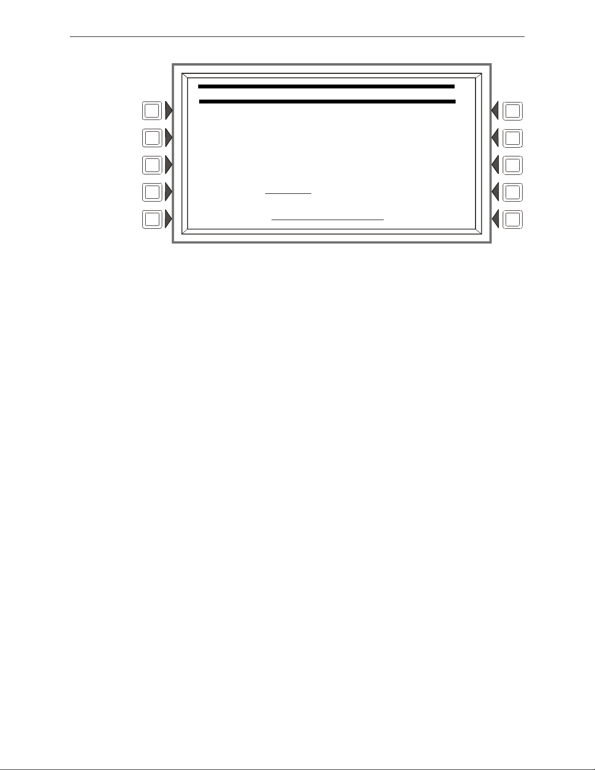
Panel Program Program
LCD PROGRAMMING
LCD INTENSITY: 50%
BRIGHTER DEFAULT
DARKER CURRENT
LANGUAGE: ENGLISH ACCEPT
BACKLIGHT ON EXCEPT AC FAIL BACK
Figure 3.16 LCD Display Screen
Soft Keys
BRIGHTER: Press this s
oft key to increase contrast. The intensity will increase by approximately
5% with each press of the key.
DARKER: Press this
soft key to decrease contrast. The intensity will decrease by approximately
5% with each press of the key.
LANGUAGE: Press this so
ft to choose the language that will display on the LCD. Menu choices are
ENGLISH, HEBREW, PORTUGUESE and SPANISH.
To change the language display o
n an LCD-160, refer to Section 5.3.1, “LCD-160 Download
Menu”, on page 88.
BACKLIGHT: Press th
is soft key to select one of the following backlighting options: ON EXCEPT
AC FAIL, OFF, or ON. When ON EXCEPT AC FAIL is selected, the backlight will turn off when
the power supply experiences AC failure.
Default: ON
DEFAULT: Press to select th
CURRENT:Press
to select the intensity that was in effect when the screen was accessed.
ACCEPT: Line 5 (whi
e factory default setting (40%).
ch displays LCD INTENSITY: 50% in the figure above) will change
value when the INTENSITY soft keys are pressed. Press ACCEPT to save the desired setting.
3.2.8 ACS Programming
An ACS device is a remote device used by the panel to annunciate certain system messages, and/or
to act with limited commands. A total of 32 annunciator devices may be present on the EIA-485
NFS2-3030 Programming Manual — P/N 52545:K1 03/20/2012 29
ACS circuit; however, some devices have associated expander devices, and an NFS2-3030 ACS
circuit can accommodate up to 3,072 annunciator points. The ACS Programming and ACS Point
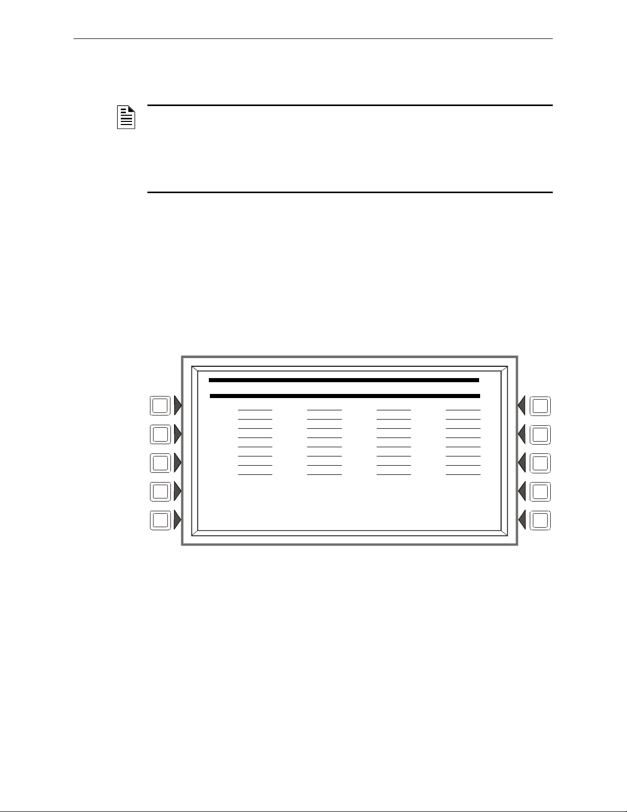
Program Panel Program
ACS PROGRAMMING
A01:64PT A02:64SYS A03:96PT A04:TM4
A05:UDACT A06:96SYS A07:FSCS A08:UZC
A09: NO A10: NO A11: NO A12: NO
A13: NO A14: NO A15: NO A16: NO
A17: NO A18: NO A19: NO A20: NO
A21: NO A22: NO A23: NO A24: NO
A25: NO A26: NO A27: NO A28: NO
A29: NO A30: NO A31: NO A32:AMG
ANNUNCIATOR TYPE ACCEPT
POINT PROGRAMMING BACK
Programming screens in this section allow the user to define the mapping and functional mode of
these devices and points. Each annunciator board may be labeled using the ACS Label Menu.
(Refer to Section 3.4.7, “Annunciator Board Label”, on page 63).
NOTE: Smoke Control devices must be set as FSCS or HVAC annunciator types. In addition to
its 64 smoke control points, when an SCS device is operating in FSCS (Firefighters Smoke
Control Station) mode, there are 32 additional points which function as alarm points. They can be
mapped to a zone or point to send the SCS device into a fire alarm state when any of the
additional 32 points is activated. Any of the 32 alarm points that are used must be set to
MONITOR mode from the panel. Any of these points that are not used can be set to NONE. Refer
to the SCS manual for further information on Smoke Control devices.
UDACT/UDACT-2 and TM-4 communicators, as
well as the UZC Zone Coder, are installed on the
same EIA-485 ACS circuit as annunciators, and so are included with annunciator programming.
The TM-4 occupies one of the 32 annunciator addresses, and the UDACT or UDACT-2 can occupy
one or more of these addresses. The UZC can occupy up to four annunciator addresses, each with
64 points. When the UDACT/UDACT-2 or UZC expand beyond one annunciator address, 64PT
should be used for the subsequent address types, and the annunciator addresses should be
sequential. Other than address assignment, there is no ACS point programming for these devices.
Refer to the specific device manual for more information.
invoke the following screen.
Press the ACS Programming soft key at the Panel Program screen to
Press the up and down arrow keys on the keypad to navigate through the annunciator addresses.
There will be a cursor highlighted at the current annunciator address position.
Figure 3.17 ACS Programming Screen
30 NFS2-3030 Programming Manual — P/N 52545:K1 03/20/2012
 Loading...