

Honeywell MS9520, MS9520–11, MS9540, MS9520–00, MS9520–14 User Manual
...
MS9500 Voyager® Series
Single-Line Hand Held Laser Scanner
Installation and User's Guide

Disclaimer
Honeywell International Inc. (“HII”) reserves the right to make changes in
specifications and other information contained in this document without prior
notice, and the reader should in all cases consult HII to determine whether any
such changes have been made. The information in this publication does not
represent a commitment on the part of HII.
HII shall not be liable for technical or editorial errors or omissions contained
herein: nor for incidental or consequential damages resulting from the furnishing,
performance, or use of this manual.
This document contains propriety information that is protected by copyright. All
rights reserved. No part of this document may be photocopied, reproduced, or
translated into another language without the prior written consent of HII.
© 2009 Honeywell International Inc. All rights reserved.
Web Address: www.honeywellaidc.com
Trademarks
Metrologic, MetroSelect, MetroSet2, and CodeGate are trademarks or registered
trademarks of Metrologic Instruments, Inc. or Honeywell International Inc.
Microsoft, Windows, and Windows 95 are trademarks or registered trademarks of
Microsoft Corporation.
IBM is a trademark of International Business Machines Corporation.
Other product names mentioned in this manual may be trademarks or registered
trademarks of their respective companies and are the property of their respective
owners.
Patents
Please refer to page 40 for a list of patents.

TABLE OF CONTENTS
Introduction
Product Overview ............................................................................................. 1
Scanner and Accessories................................................................................. 2
Scanner Components....................................................................................... 4
The PowerLink Cable
Labels............................................................................................................... 6
Maintenance..................................................................................................... 6
Installing the Scanner to the Host System
RS232, Laser Emulation, and Light Pen Emulation.......................................... 7
RS485 .............................................................................................................. 8
Keyboard Wedge.............................................................................................. 9
Stand-Alone Keyboard ................................................................................... 10
Integrated USB
The MS9540 VoyagerCG® Series
How to Use CodeGate® and the Manual Activation Mode.............................. 12
Three Modes of Operation.............................................................................. 12
Stand Kits
Types.............................................................................................................. 13
Assembly........................................................................................................ 14
Indicators
Audible ........................................................................................................... 17
Visual ............................................................................................................. 18
Failure Modes................................................................................................. 19
Configuration Modes .......................................................................................... 20
Upgrading the Firmware..................................................................................... 23
Depth of Field ..................................................................................................... 24
Disconnecting............................................................................................... 5
Connecting ................................................................................................... 5
Full Speed .................................................................................................. 11
Low Speed ................................................................................................. 11
ii

TABLE OF CONTENTS
IR Activation Range............................................................................................ 25
Applications and Protocols ................................................................................. 26
Troubleshooting Guide ....................................................................................... 27
Design Specifications
Operational.....................................................................................................30
Mechanical ..................................................................................................... 31
Electrical......................................................................................................... 31
Environmental ................................................................................................ 31
Scanner and Cable Terminations
Scanner Pinout Connections.......................................................................... 32
Cable Connector Configurations .................................................................... 34
Limited Warranty ................................................................................................ 36
Regulatory Compliance
Safety ............................................................................................................. 37
EMC ............................................................................................................... 38
Patents ............................................................................................................... 40
Index .................................................................................................................. 41
Customer Support .............................................................................................. 43
Technical Assistance...................................................................................... 43
Product Service and Repair............................................................................ 44
iii
INTRODUCTION
Product Overview
Honeywell’s MS9500 Voyager® series of hand-held (single-line) laser scanners
offers the user an aggressive solution for scanning all standard 1D bar codes
including GS1 DataBar™ (RSS) bar codes. The MS9500 series is equipped with
both in-stand and out-of-stand operation enabling hand-held or fixed projection
scanning. The MS9520 Voyager model includes all of the same features as the
MS9540 VoyagerCG model, with the exception of Honeywell’s patented
CodeGate® technology.
The MS9540, VoyagerCG incorporates Honeywell’s patented auto-trigger and
CodeGate button feature. When a bar code is place in the scanner’s IR range,
the auto-trigger activates the laser enabling the user to align the visible laser line
over the bar code selected for scanning. The user can then press the CodeGate
button, to transmit the data to the host system. When the MS9540 is placed in
the stand the CodeGate button feature will automatically deactivating for hands
free operation.
Some additional key product features for the MS9500 series include:
• Auto-trigger operation and auto-stand detect
• CodeGate data transmission technology (MS9540 only)
• Flash – upgradeable firmware
®
• Easy configuration with MetroSelect
Windows
®
compatible software
• Support for common interfaces including USB (see chart below)
VOYAGER VOYAGERCG INTERFACE
bar codes and MetroSet®2
MS9520 – 00 MS9540 – 00 Laser Emulation RS232 Transmit/Receive
MS9520 – 11 MS9540 – 11
MS9520 – 14 MS9540 – 14 RS232 (TXD, RXD, RTS, CTS, DTR, DSR)
MS9520 – 38 MS9540 – 38
MS9520 – 40 MS9540 – 40 Full Speed USB, RS232 (TXD, RXD, RTS, CTS)
MS9520 – 41 MS9540 – 41 RS232/Light Pen Emulation
MS9520 – 47 MS9540 – 47
* Configurable for Keyboard Emulation Mode or Serial Emulation Mode. The default
setting is Keyboard Emulation Mode.
Applicable for IBM® host applications.
, RS232 (TXD, RXD, RTS, CTS)
RS485
Low Speed USB*, TTL RS232 (TXD, RXD, RTS,
CTS)
Keyboard Wedge, Stand-Alone Keyboard and TTL
RS232 Transmit/Receive
1
INTRODUCTION
Scanner and Accessories
BASIC KIT
Part # Description
MS9520
or
MS9540
00-02544 MetroSelect Single-Line Configuration Guide*
Voyager Bar Code Scanner
or
VoyagerCG Bar Code Scanner with CodeGate
00-02410
MS9500 Voyager Series Single-Line Hand Held Laser
Scanner Installation and User’s Guide*
* Available for download at - www.honeywellaidc.com
OPTIONAL ACCESSORIES
Part # Description
AC to DC Power Transformer - Regulated 5.2VDC @ 1A output.
46-00525 90VAC to 255VAC, United States, Canada and Japan
46-00526 90VAC to 255VAC, Continental European
46-00527 90VAC to 255VAC, United Kingdom
46-00528 90VAC to 255VAC, Australia
46-00529 90VAC to 255VAC, China
53-53000x-3
59-59000x-3
53-53002x-3
RS232 PowerLink Cable with Built in Power Jack
Black, Coiled Cord, with Long Strain Relief
RS232 PowerLink Cable with Built in Power Jack
Black, Straight cord, with Short Strain Relief
Keyboard Wedge PowerLink Cable with Adapter Cable
Black, Coiled cord, with Long Strain Relief
53-53020x-3
Other items may be ordered for the specific protocol being used. To order additional items,
contact the dealer, distributor or a customer service representative.
Stand Alone Keyboard Wedge PowerLink Cable
Black, Coiled cord, with Long Strain Relief
2
INTRODUCTION
Scanner and Accessories
OPTIONAL ACCESSORIES
Part # Description
53-53213x-N-3
USB Full Speed Cable Locking Plus-Power™ Type A,
Black, Coiled Cord with Long Strain Relief
USB Full Speed Cable Locking Plus-Power™ Type A,
Black, Coiled Cord with Long Strain Relief, Extended
53-53214x-N-3
Length
Not for use with Low Speed USB scanners.
53-53235x-N-3
Use with Full Speed USB scanners only.
USB Low Speed Communication Cable, Type A
Black, Coiled Cord with Long Strain Relief
MVC** RS485 MVC Cable ±12VDC to +5.2VDC
** Contact a customer service representative for additional information on
the MVC converter cable series and the host connections available.
46-46128 Free-Standing Stand with Accessories
46-46351 Hard Mount Accessory Kit (used with kit #46-46128)
46-46508 Wall Mount Hanger Accessory Kit
Other items may be ordered for the specific protocol being used. To order additional items,
contact the dealer, distributor or a customer service representative.
3

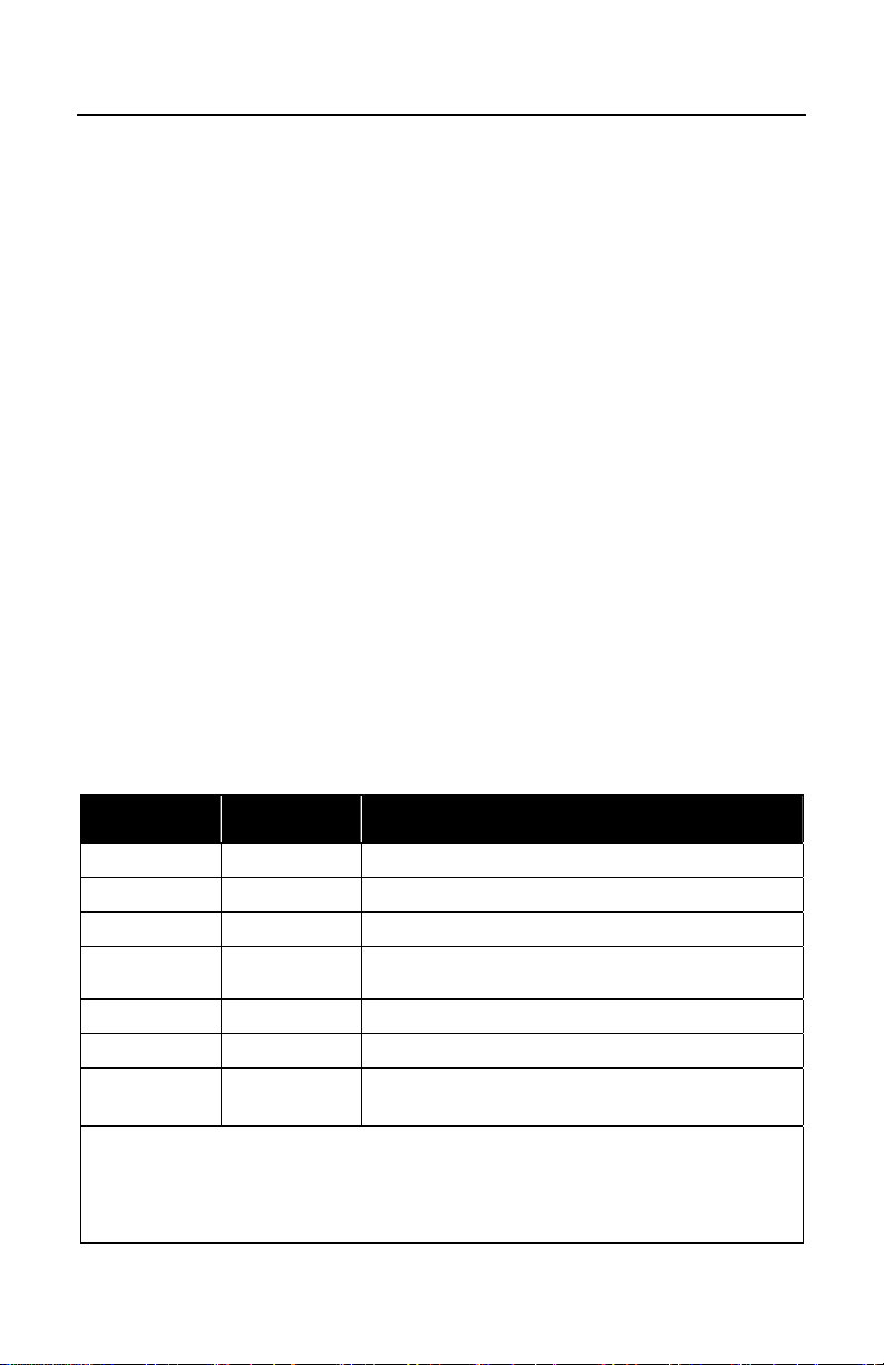
INTRODUCTION
Scanner Components
No. Item Description
Green LED
1
Red LED
2
Yellow LED
3
Button
4
♦
♦
♦♦
♦♦
See Visual Indicators on page 18
See Visual Indicators on page 18
See Visual Indicators on page 18
See How to use CodeGate on page 12
5 Red Window Laser Aperture
6 Speaker See Audible Indicators on page 17
7 Cable Release Pin-Hole See The PowerLink Cable on page 5
8 Cable Connection
♦
In some custom units the standard green LED has been replaced with a
10-pin RJ45, Female Socket,
See Scanner Pinout Connections on page 32
Figure 1. Scanner Components
blue LED and the red LED has been replaced with a white LED.
♦♦
Items are provided with the MS9540, VoyagerCG model only.
4
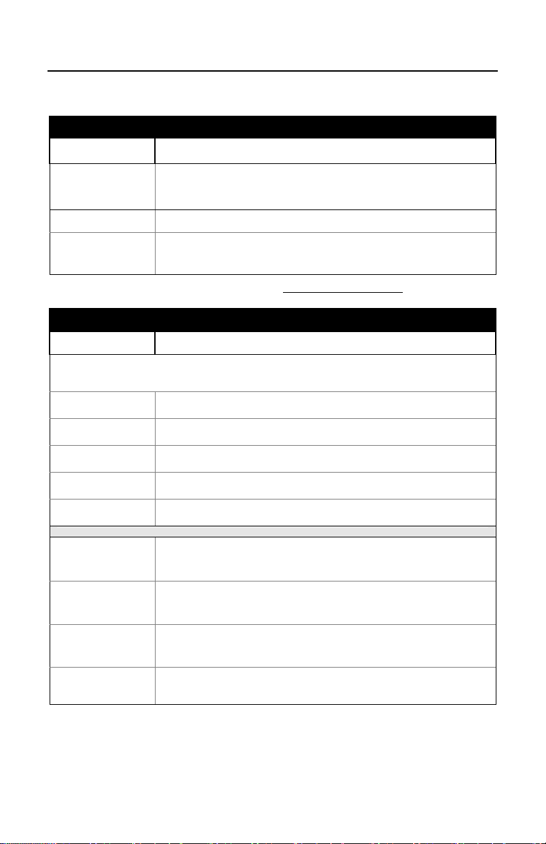
INTRODUCTION
Disconnecting the PowerLink Cable
Before removing the cable from the scanner, Honeywell recommends that the
power on the host system is off and the power supply has been disconnected
from the PowerLink cable.
Figure 2.
1. Locate the small ‘pin-hole’ on the top of the unit near the bottom of the
scanner.
2. Bend an ordinary paperclip into the shape shown above.
3. Insert the paperclip (or other small metallic pin) into the small ‘pin-hole’.
4. There will be an audible click when the connector lock releases. Pull gently
on the strain-relief of the PowerLink cable to separate the cable from the
scanner.
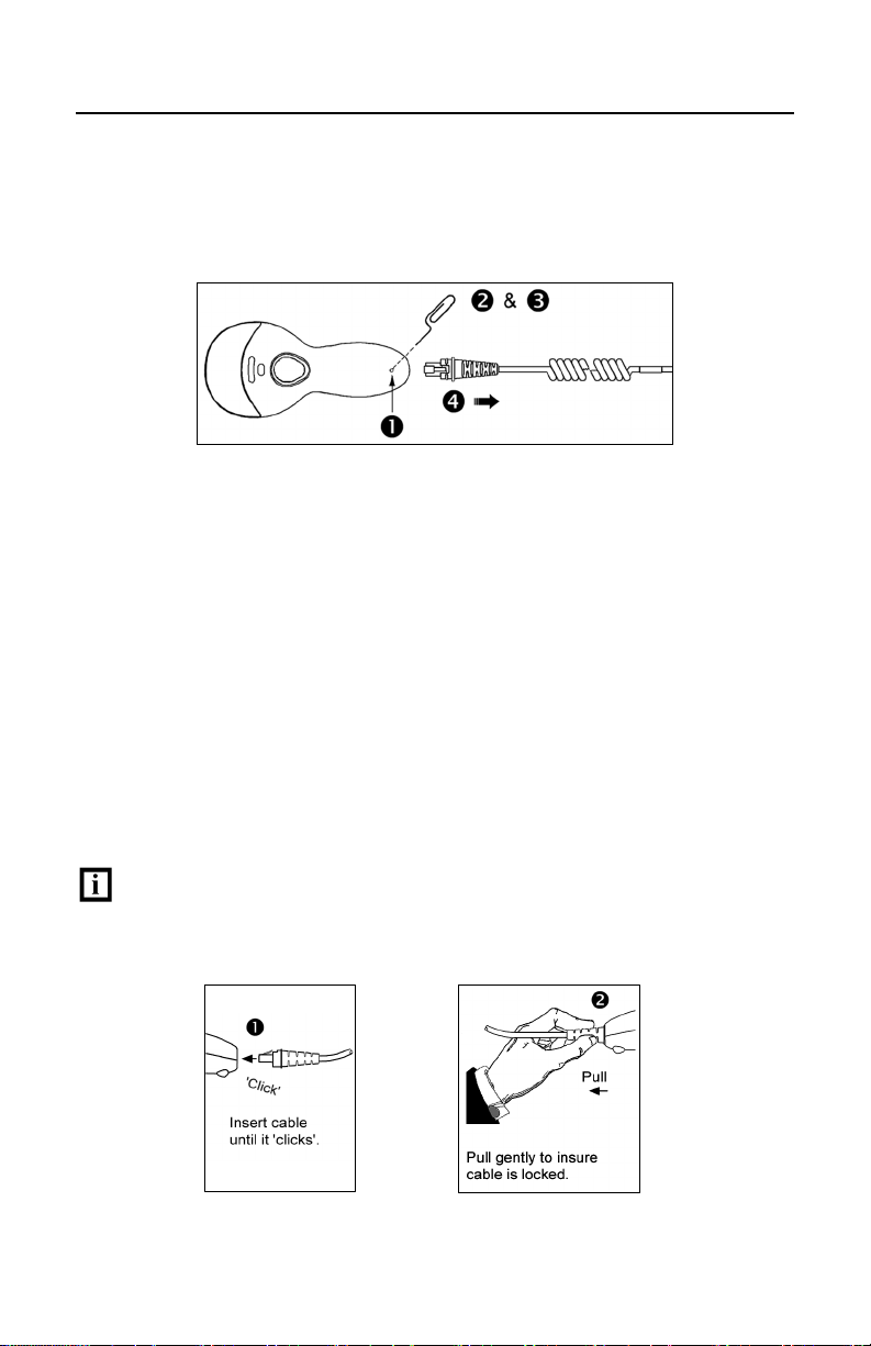
Connecting the PowerLink Cable
Important: If the PowerLink cable is not fully latched, the unit can power
intermittently.
Figure 3.
Figure 4.
5
INTRODUCTION
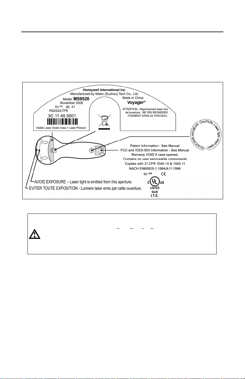
Labels
Every scanner has labels and molded text located on the underside of the unit.
The labels and text contain important information such as the unit’s date of
manufacture, serial number, CE and caution information. Figure 5 provides
examp
les of the labels and the molded text.
Figure 5 . Molded Text and Label Examples
Caution:
To maintain compliance with applicable standards, all circuits connected to the scanner
must meet the requirements for SELV (Safety Extra Low Voltage) according to EN/IEC
60950-1.
To maintain compliance with standard CSA-C22.2 No. 60950-1/UL 60950-1 and norm
EN/IEC 60950-1, the power source should meet applicable performance requirements for
a limited power source.
Maintenance
Smudges and dirt on the unit's window can interfere with the unit's performance.
If the window requires cleaning, use only a mild glass cleaner containing no
ammonia. When cleaning the window, spray the cleaner onto a lint free,
non-abrasive cleaning cloth then gently wipe the window clean.
If the unit's case requires cleaning, use a mild cleaning agent that does not
contain strong oxidizing chemicals. Strong cleaning agents may discolor or
damage the unit's exterior.
6
INSTALLING THE SCANNER TO THE HOST SYSTEM
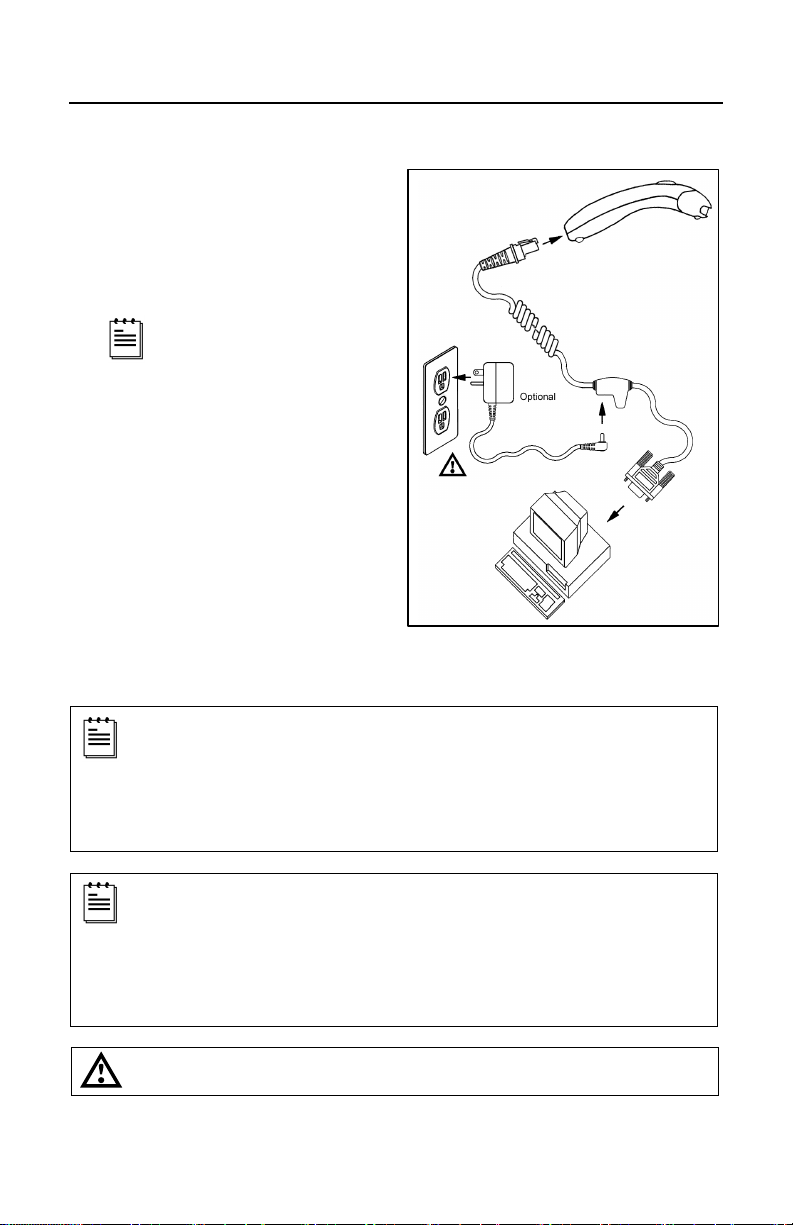
RS232, Laser Emulation, and Light Pen Emulation
1. Turn off the host system.
2. Connect the 10-pin RJ45 male
connector into the jack on the
scanner. There will be an audible
click when the connector lock
engages.
3. Connect the L-shaped plug of the
4. Verify the AC input requirements of
5. Connect the PowerLink cable to
6. Turn on the host system.
If the scanner is receiving
power from the host system,
skip to step #5.
power supply into the power jack
on the PowerLink cable.
the power supply match the AC
outlet. Connect the power supply
into an AC outlet. The outlet should
be near the equipment and easily
accessible.
the proper port on the host system.
Figure 6.
Plugging the scanner into a port on the host system does not guarantee
that scanned information will be communicated properly to the host
system. Please refer to the MetroSelect Single-Line Configuration
Guide or MetroSet2’s help files for instructions on changing the
scanner’s factory default configuration. The scanner and host system
must use the same communication protocols.
All MS95x0-00 scanners leave the factory with the Laser Emulation
Mode enabled. If you recall defaults while re-configuring your scanner
the Laser Emulation Mode will no longer be enabled. Refer to the
MS95x0-00 Laser Emulation Mode section of the MetroSelect SingleLine Configuration Guide for information on enabling the Laser
Emulation Mode.
See caution on page 6
.
7
INSTALLING THE SCANNER TO THE HOST SYSTEM
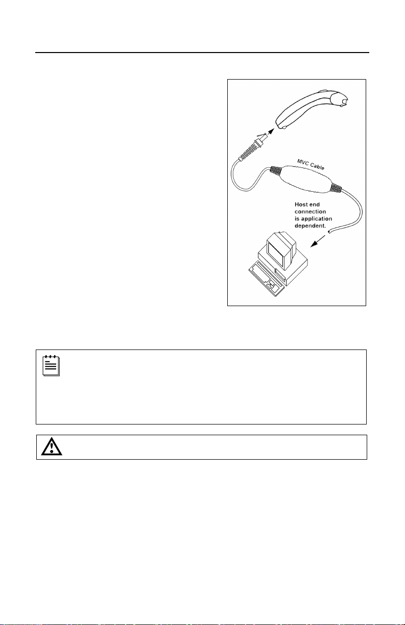
RS485
Turn off the host system.
1.
2. Plug the male 10-pin RJ45 end of the
MVC cable into the 10-pin socket on
the scanner. There will be an audible
click when the connection is made.
3. Connect the other end of the MVC
cable to the host device.
4. Turn on the host system.
ging the scanner into a port on the host system does not guarantee
Plug
that scanned information will be communicated properly to the host
system. Please refer to the MetroSelect Single-Line Configuration
Guide or MetroSet2’s help files for instructions on changing the
scanner’s factory default configuration. The scanner and host system
must use the same communication protocols.
See caution on page 6.
Figure 7.
8

INSTALLING THE SCANNER TO THE HOST SYSTEM
Keyboard Wedge
1. Turn off the host system.
2. Connect the 10-pin RJ45 male
connector into the jack on the scanner.
There will be an audible click when the
connection is made.
If the scanner is receiving
power from the host system,
3. Connect the L-shaped plug of the
4. Verify the AC input requirements
5. Disconnect the keyboard from the PC.
6. Connect the PowerLink cable to the
7. Power up the host system.
skip to step #5.
power supply into the power jack on
the PowerLink cable.
of the power supply match the AC
outlet. Connect the power supply into
an AC outlet. The outlet should be near
the equipment and easily accessible.
keyboard and the PC’s keyboard port.
If necessary use the supplied adapter
cable (5-pin male DIN to 6-pin female
mini DIN adapter).
Plugging the scanner into a port on the host system does not guarantee that
scanned information will be communicated properly to the host system. Please
refer to the MetroSelect Single-Line Configuration Guide or MetroSet2’s help files
for instructions on changing the scanner’s factory default configuration.
The scanner and host system must use the same communication protocols.
Powering the MS95x0-47 directly from the computer can sometimes cause
interference with the operation of the scanner or the computer. Not all computers
supply the same current through the keyboard port, explaining why a scanner
may work on one computer and not another. Contact a Customer Service
Representative if you require an external power supply.
Figure 8.
See caution on page 6.
9

INSTALLING THE SCANNER TO THE HOST SYSTEM
Stand-Alone Keyboard
1. Turn off the host system.
2. Connect the 10-pin RJ45 male
connector into the jack on the
scanner. There will be an audible
click when the connection is made.
If the scanner is receiving
power from the host system,
skip to step #5.
3. Connect the L-shaped plug of the
power supply into the power jack
on the PowerLink cable.
4. Verify the AC input requirements
of the power supply match the AC
outlet. Connect the power supply
into an AC outlet. The outlet
should be near the equipment and
easily accessible.
5. Connect the PowerLink cable
to the keyboard port on the host
system.
6. Turn on the host system.
Powering the MS95x0-47 directly from the computer can sometimes cause
interference with the operation of the scanner or the computer. Not all computers
supply the same current through the keyboard port, explaining why a scanner
would work on one computer and not another. Contact a Customer Service
Representative if you require an external power supply.
Plugging the scanner into a port on the host system does not guarantee that
scanned information will be communicated properly to the host system. Please
refer to the MetroSelect Single-Line Configuration Guide or MetroSet2’s help files
for instructions on changing the scanner’s factory default configuration.
The scanner and host system must use the same communication protocols.
See caution on page 6.
Figure 9.
10
INSTALLING THE SCANNER TO THE HOST SYSTEM
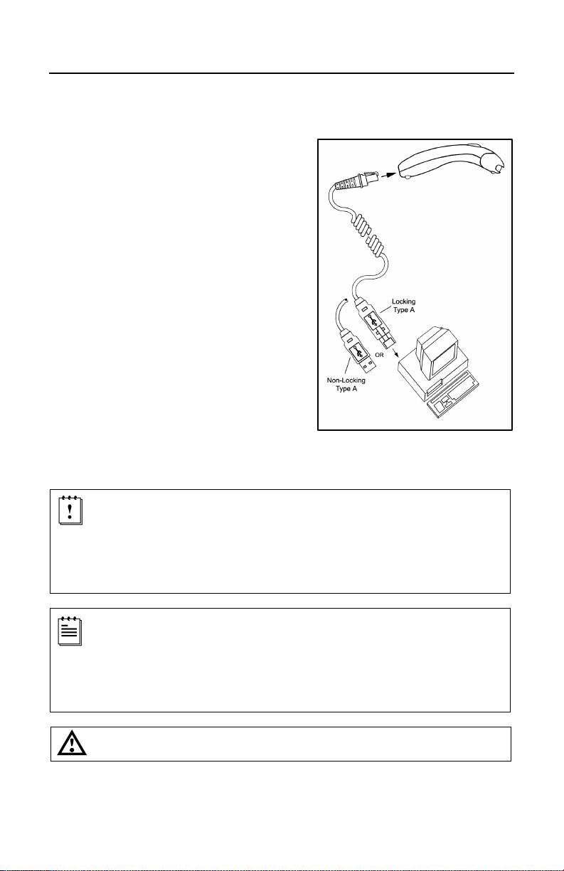
Integrated USB: Full Speed (-40)
Low Speed (-38)
Turn off the host system.
1.
2. Connect the 10-pin RJ45 male
connector of the USB cable into the
jack on the scanner. There will be an
audible click when the connection is
made.
3. Connect the other end of the USB
cable to the host USB port.
4. Turn on the host system.
As a default, th
Emulation Mode enabled.
For information on configuring the MS95x0-38 for USB Serial
Emulation Mode, please refer to the USB section of the MetroSelect
Single-Line Configuration Guide (PN 00-02544).
Plugging the scanner into a port on the host system does not guarantee
that scanned information will be communicated properly to the host
system. Please refer to the MetroSelect Single-Line Configuration
Guide or MetroSet2’s help files for instructions on changing the
scanner’s factory default configuration. The scanner and host system
must use the same communication protocols.
See caution on page 6.
e MS95x0-38 leaves the factory with USB Keyboard
Figure 10.
11
THE MS9540 VOYAGERCG
®
SERIES
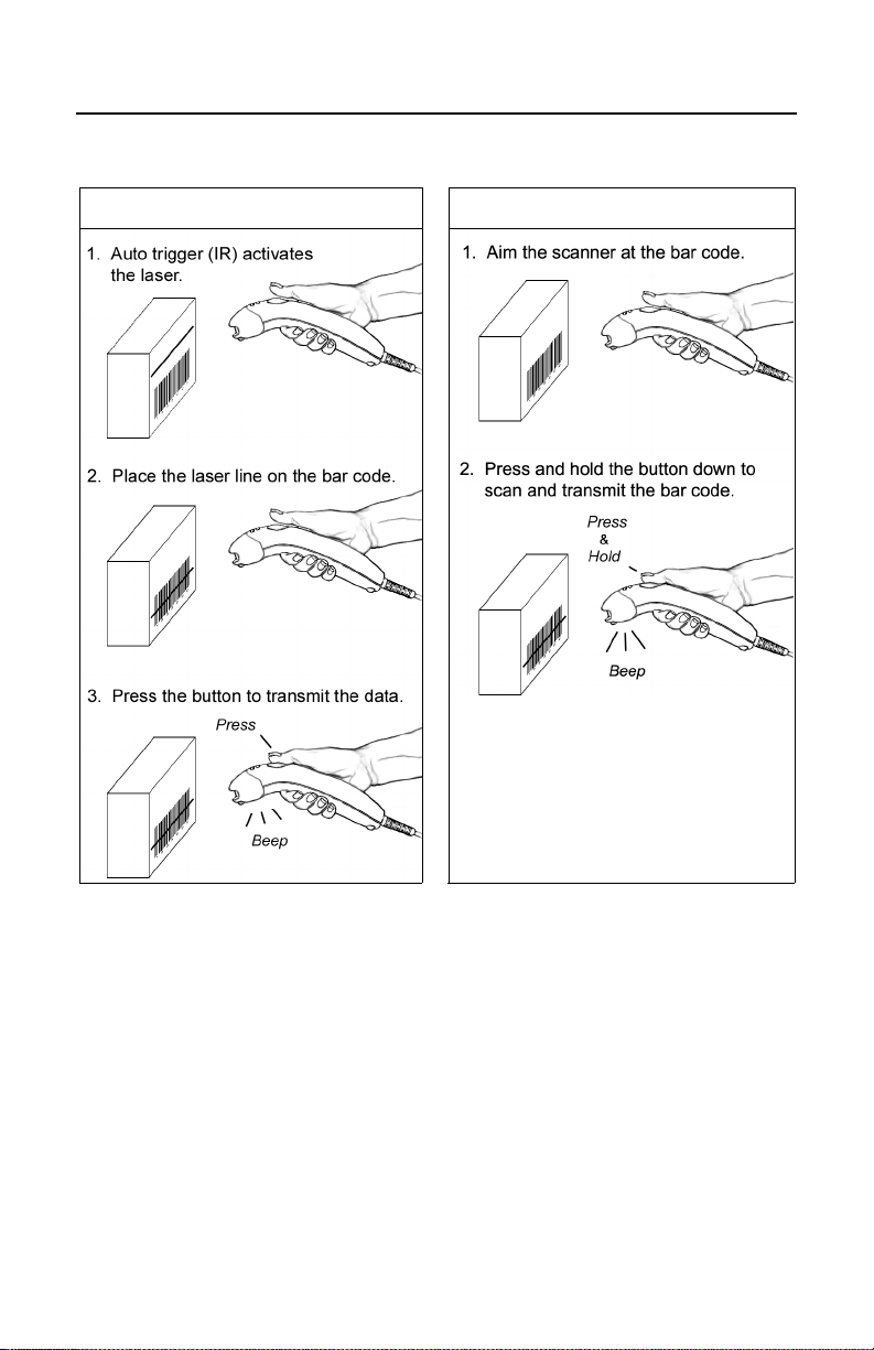
How to Use CodeGate and the Manual Activation Mode
CODEGATE® MANUAL ACTIVATION MODE*
* This feature is not a default setting.
Refer to the MetroSelect Configuration
Guide for instructions on enabling the
Manual Activation Mode.
Figure 11.
Three Modes of Operation
Figure 12.
Auto Trigger, In-Stand
Auto-triggers while in the stand
Bar code is automatically decoded and transmitted
CodeGate, Out-of-Stand
CodeGate activates when removed from the stand
Bar code data is transmitted when the button is pressed
Manual Activation Mode*, Out-of-Stand
Button activates laser
Bar code data is scanned and transmitted while button is held down
12
 Loading...