

Honeywell MS9500 Stand Installation Manual
PARTS CHECKLIST
Kit #46-46128 Contains:
a. Stand
(PN 36-00454)
b. Screw, MS3 x 6 mm
(PN 18-18670)
c. Washer, #5 x .5 OD
(PN 18-18671)
d. Stand Anchor
(PN 50-50449)
e. M3 x 20 mm Set Screw
(PN 18-18672)
f. Apron
(PN 50-50440)
Figure 9.
Special Purchase Kit #46-46351 Contains:
a. Wood Screw, #8 Round Head
(PN 18-18057)
b. Base
(PN 36-36080)
Figure10.
Qty. 1
Qty. 2
Qty. 2
Qty. 1
Qty. 1
Qty. 1
Qty. 4
Qty. 1
DRILL TEMPLATE
MS9500
Voyager® Series
Honeywell Scanning & Mobility
9680 Old Bailes Road
Fort Mill, SC 29707
www.honeywellaidc.com
00-02497 Rev B
December 2009
Stand Installation Guide
Page 4 Page 5

FREE – STANDING INSTALLATION
For Kit #46-46128:
Step 1
Slide the apron (PN 50-50440) over the stand
(PN 36-00454).
Figure 1.
Step 2
Position the stand so it sits under the tab on the
apron. Then secure the apron to the stand using
the M3 screws (PN 18-18670) and the #5 washers
(PN 18-18671) provided.
HARD MOUNT INSTALLATION
HARD MOUNT INSTALLATION
Step 4
Remove the logo plate on the stand by gently
using an exacto knife to release the plate hook.
Figure 5.
Step 5
Position the stand over the anchor/base assembly.
For Kit #46-46351:
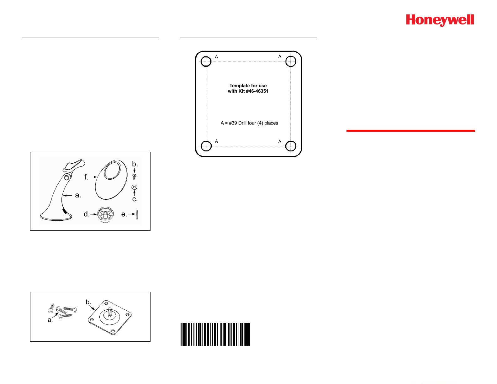
Step 1
Use the template provided to drill four #39 pilot
holes in the counter top.
Step 2
Secure the base (PN 36-36080) to the countertop
with the four #8 wood screws (PN 18-18057).
Figure 6.
Step 6
Secure the stand to the base assembly by
installing and tightening the M3 hex head screw
(PN 18-18672) under the logo plate as shown.
Figure 3.
For Kit #46-46128, #46-46351, and MS951 Stand
Replacements:
Step 3
Screw the stand anchor (PN 50-50449) onto the
base assembly until it sits flush.
Figure 2.
Page 1 Page 2 Page 3
Figure 4.
Step 7
Snap the logo plate back into place.
Figure 7.
Figure 8.
 Loading...