

Honeywell MS8103A1030, MS3103J1030, MS7503A2030, MS7403A2030, MS7503A2130 Installation Instructions Manual
...
3 Nm, 5 Nm Series Spring Return
N314
Direct Coupled Actuators
MS3103, MS3105, MS4103, MS4105, MS7403, MS7405, MS7503,
MS7505, MS8103, MS8105
INSTALLATION INSTRUCTIONS
MS3103, MS3105, MS4103, MS4105, MS7403, MS7405,
MS7503, MS7505, MS8103, MS8105 Spring Return Direct
Coupled Actuators (DCA) are used within heating, ventilating,
and air-conditioning (HVAC) systems. They can drive a variety
of quarter-turn, final control elements requiring spring return
fail-safe operation.
Applications include:
• Volume control dampers, mounted directly to the drive
shaft or remotely (with the use of accessory hardware).
• Quarter-turn rotary valves, such as ball or butterfly valves
mounted directly to the drive shaft.
• Linear stroke globe or cage valves mounted with linkages
to provide linear actuation.
• Available with cable on select models
Table 1. Models.
Power Supply
Model Number
Model Number
MS3103J1030 27 lb-in
MS7403A2030
MS7503A2030
MS7503A2130 1
MS8103A1030 45 Two-Position (SPST) 0
MS8103A1130 1
MS4103A1030 100-250 Vac
MS4103A1130 1
MS3105J3030 44 lb-in
MS3105J3130 1
MS7405A2030
MS7505A2030 MS7505W2030
MS7505A2130 MS7505W2130 1
MS8105A1030 MS8105W1030 45 Two-Position (SPST) 0
MS8105A1130 MS8105W1130 1
MS4105A1030 100-250 Vac
MS4105A1130 1
1
Number represents range
2
2-10 Vdc
3
0/2-10 Vdc
(including 3 ft. whip) Torque Voltage
24 Vac/dc
(3 Nm)
(5 Nm)
@50/60 Hz +/-
20%
24Vdc+/-10%
@50/60Hz
24 Vac/dc
@50/60 Hz +/-
20%
24Vdc+/-10%
@50/60Hz
Driving
SPECIFICATIONS
Models:
See Table 1.
Device Weight:
3.5 lbs (1.60 kg)
Ambient Operating Temperature:
-40° to 150°F (-40° to 65°C)
-22° to 150°F (-30° to 65°C) (Two position only)
Shipping and Storage Temperature:
-40° to +150°F (-40° to +65°C)
VA
Drive
1
(sec) Control Input/Output Description
6/3 90 Sylk-enabled 0
Floating, Modulating
Floating, Modulating
6/9 45 Two-Position (SPST) 0
6/3 90 Sylk-enabled (5 addresses & Analog Output) 0
Floating, Modulating
Floating, Modulating3, and Feedback
6/9 45 Two-Position (SPST) 0
2
,Three-Position, Feedback
3
, and Feedback
2
, Three-Position, Feedback
Switch
SPDT
Aux
0
0
0
0
62-0274-07
3 NM, 5 NM SERIES SPRING RETURN DIRECT COUPLED ACTUATORS
M28945
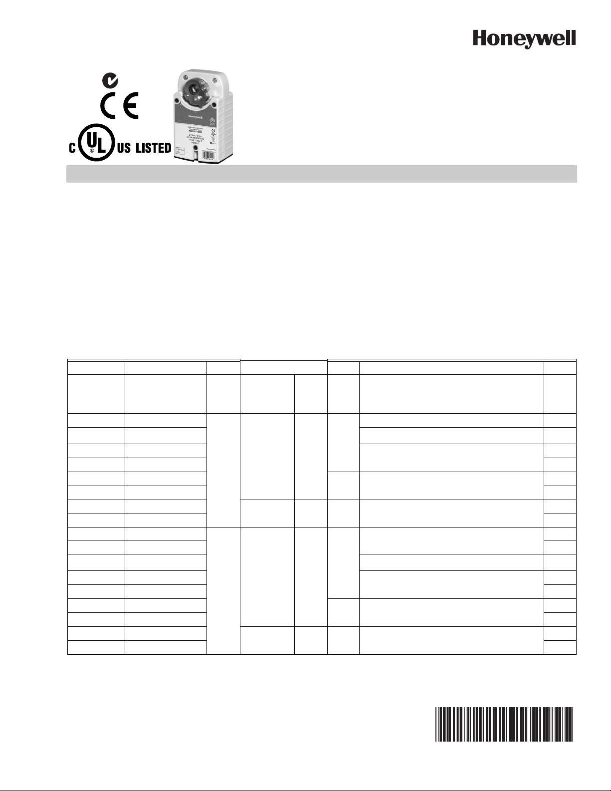
3-55/64 (98)
6-61/64
(177)
1-1/8
(29)
5-27/32
(148)
1-9/16
(40)
3-5/32 (80)
4-9/16
(116)
1-15/16
(49)
1-1/16
(27)
2-1/64
(55)
47/64
(19)
2-27/64 (61)
36 (914)
1
1
CABLE AND STRAIN
RELIEF ON SELECT
MODELS ONLY.
Humidity Ratings:
5% to 95% R.H., Non-Condensing
Electrical Connections:
Field wiring 18 AWG (0.5 mm) to 14 AWG (1.5 mm)
conductors (stranded or solid) and up to 2 - 14 AWG (1.5
mm) conductors (stranded) to screw terminals, located
under the removable access cover.
Auxiliary Switch (One SPDT):
Switch adjustable from 0-95°
500 uA Resistive at 5 Vdc (minimum)
250 Vac, 8 A resistive, 3 A inductive
Mounting: Self-centering shaft adapter (shaft coupling):
Round damper shafts: 3/8 to 5/8 in. (9 to 16 mm)
Square damper shafts: 1/4 to 1/2 in. (6 to 13 mm)
Minimum Damper Shaft Length:
1 in. (25 mm); 3 in.(76 mm) recommended.
Spring Return Timing (at rated load):
< 25 seconds @ -4°F to 130°F (-20°C to 55°C)
< 60 seconds @ -22°F (-30°C)
Cable Specification:
300 V, 75° C, Plenum Rated, 3 ft length from end of access
cover, 18 AWG
Sylk™ Bus:
Sylk is a two-wire, polarity insensitive bus that provides
communications between a Sylk-enabled actuator and a
Sylk-enabled controller. For wiring, the Sylk-enabled
actuator may be mounted up to 200 ft. (61 m) from the
controller; twisted pair wire is recommended for wire runs
longer than 100 ft. (30.5 m). Using Sylk-enabled actuators
saves I/O on the controller and is faster and cheaper to
install since the bus is polarity insensitive.
Stroke:95° ±3°, mechanically limited.
Approvals:
UL873
IEC 60730-1 and Part 2–14
UL1097 for Double Insulation
CE Certification Low Voltage Directive 2006/95/EC
CE EMC 2004/108/EC
C-Tick N314
Enclosure Ratings:
IP54
NEMA 2
Flame Resistance UL94-5VA
Input Impedance:
95 kOhm minimum.
Feedback Signal:
0(2)-10 Vdc, 3 mA minimum.
Analog Output Signal:
0(2)-10 Vdc
Noise Rating at 1m (Maximum):
Driving
Floating/Modulating/Econ/Sylk-enabled: < 40 dB(A)
2-Position: < 50 dB(A)
Spring Return: < 60 dB(A)
Accessories:
27518 Balljoint (5/16 in.)
103598 Balljoint (1/4 in.)
27520B, C, E, G, H, K, L, Q Pushrod (5/16 in. diameter)
STRN-STRNRLF Water-tight Cable Gland/Strain-relief
Fitting (10 pack)
STRN-WMK-01 Wall Mount Kit
STRN-ECONO-01 Economizer Retrofit Kit
STRN-CRK-01 Crank Arm Kit
STRN-SCSA Self Centering Shaft Adapter
STRN-CA-01 Crank Arm (Non-Self-Centering)
STRN-CA-02 Crank Arm (Self-Centering)
STRN-BRKT Anti-Rotation Bracket
62-0274—07 2
Fig. 1. Dimensional drawing of actuator in in. (mm).

TYPICAL SPECIFICATION
CAUTION
CAUTION
CAUTION
Spring return actuators shall be direct coupled type requiring
neither crankarm nor linkage and be capable of direct mounting
to a jackshaft of up to 5/8 in. diameter. The actuator shall connect
to the shaft using a removable output hub with a self-centering
shaft coupling. This coupling shall provide concentric mounting
and include an integral adjustable range-stop mechanism.
The actuator shall provide two-position, floating, proportional, or
Sylk bus control. Proportional control refers to direct acceptance
of 0-10 Vdc, 2-10 Vdc, or (with addition of a 500 ohm resistor) a 420 mA input signal. Proportional and floating control models
shall provide a feedback signal. Sylk-enabled models provide
control and feedback via communication between the actuator
and Sylk-enabled controller. Actuators shall provide wiring terminals located within an integral access cover with conduit
connections. Proportional and floating actuators shall have a
rotation direction control switch accessible on the cover.
All spring return actuators must be designed for either clockwise
or counterclockwise fail-safe operation with a continuously
engaged mechanical spring. This spring must return the valve or
actuator to a fail-safe position within 25 seconds of power loss.
All actuators shall be designed for a minimum of 60,000 fullstroke
cycles at rated torque and temperature, 60,000 spring return
cycles and 1,500,000 repositions. Run time shall be constant and
independent of: load, temperature, and supply voltage (within
specifications). All actuators shall be UL60730 and cUL (CSA22.2)
listed, have a five year warranty, and be manufactured under ISO
9001 International Quality Control Standards. Actuators shall be
as manufactured by Honeywell.
FRONT BACK
3 NM, 5 NM SERIES SPRING RETURN DIRECT COUPLED ACTUATORS
Motor Damage Hazard.
Corrosive vapors and acid fumes can damage
metal and plastic parts.
Install motor in areas free of acid fumes and other
deteriorating vapors.
Equipment Damage Hazard.
Tightly securing actuator to damper housing can
damage actuator.
Mount actuator to allow it to float along its vertical axis.
Preparation
Before mounting the actuator onto the damper shaft,
determine the:
— Damper/valve opening direction for correct spring return
rotation. The actuator can be mounted to provide clockwise
or counterclockwise spring return by flipping or turning the
unit over.
— Damper shaft size (see the Specifications section).
INSTALLATION
When Installing this Product...
1. Read these instructions carefully. Failure to follow
them could damage the product or cause a hazardous
condition.
2. Check the ratings given in the instructions and on the
product to make sure the product is suitable for your
application.
3. Installer must be a trained, experienced service
technician.
4. After installation is complete, check out product
operation as provided in these instructions.
Electrical Shock or Equipment Damage Hazard.
Low voltage can shock individuals or short
equipment circuitry.
Disconnect power supply before installation.
IMPORTANT
Location
These actuators are designed to mount directly to a damper
external drive shaft. The shaft coupling fastens to the drive
shaft. The actuator housing includes slots which, along with
an anti-rotation bracket, secure the actuator to the damper
frame or duct work (see Fig. 7).
NOTES:
All wiring must agree with applicable codes,
ordinances and regulations.
— When mounted correctly, these slots allow the
actuator to float without rotating relative to the
damper shaft.
— Using other brackets or linkages, the actuator can
be foot-mounted or tandem-mounted.
Determine Appropriate Mounting
Orientation
The actuators are designed to open a damper by driving the
damper shaft in either a clockwise or counterclockwise
direction (see Fig. 2).
NOTES:
— Actuators are shipped in the fully closed (spring
return) position.
— An arrow on the hub points to a location on the
label to indicate the hub rotary position.
0
90
45
45
CW TO CLOSE
(FAIL-SAFE POSITION)
CCW TO OPEN
0
90
1
.5
0
.5
AUX
AUX
6
6
5
5
1
1
4
4
4
2
2
MODE
MODE
3
3
M27713
CCW TO CLOSE
(FAIL-SAFE POSITION)
CW TO OPEN
90
90
1
1
.5
.5
0
0
6
6
1
1
2
2
3
3
0
0
1
45
45
AUX
AUX
5
5
4
4
MODE
MODE
1
0
0
Spring
Spring
Spring
Spring
Return
Return
Return
Return
Fig. 2. Spring Return DCA mounting orientation.
Measure Damper/Valve Shaft Length
If the shaft is less than three inches in length, the shaft
coupling must be located between the damper/valve and
actuator housing. If the shaft length is more than three inches,
the shaft coupling may be located on either side of the
actuator housing.
3 62-0274—07
3 NM, 5 NM SERIES SPRING RETURN DIRECT COUPLED ACTUATORS
CAUTION
M32676
Spring
Return
AUX
.5
90
0
0
1
45
MODE
6
5
4
3
2
1
Spring
Return
AUX
.5
90
0
0
1
45
MODE
6
5
4
3
2
1
MODE SELECT
1 = 2... 10 VDC
2 = 10... 2 VDC
3 = 0... 10 VDC
4 = 10... 0 VDC
5 = FLOATING (FWD)
6 = FLOATING (REV)
MS74 SERIES
MODE SELECT
1 = 2...10 VDC
2 = 10...2 VDC
3 = 3K OHM NTC
THERMISTOR
4 = 3 POSITION
5 = FLOATING
(FWD)
6 = FLOATING (REV)
MS31 SERIES
MODE SELECT
1 = ADDRESS 11
2 = ADDRESS 12
3 = ADDRESS 13
4 = ADDRESS 14
5 = ADDRESS 15
6 = TEST
AUXILIARY KNOB
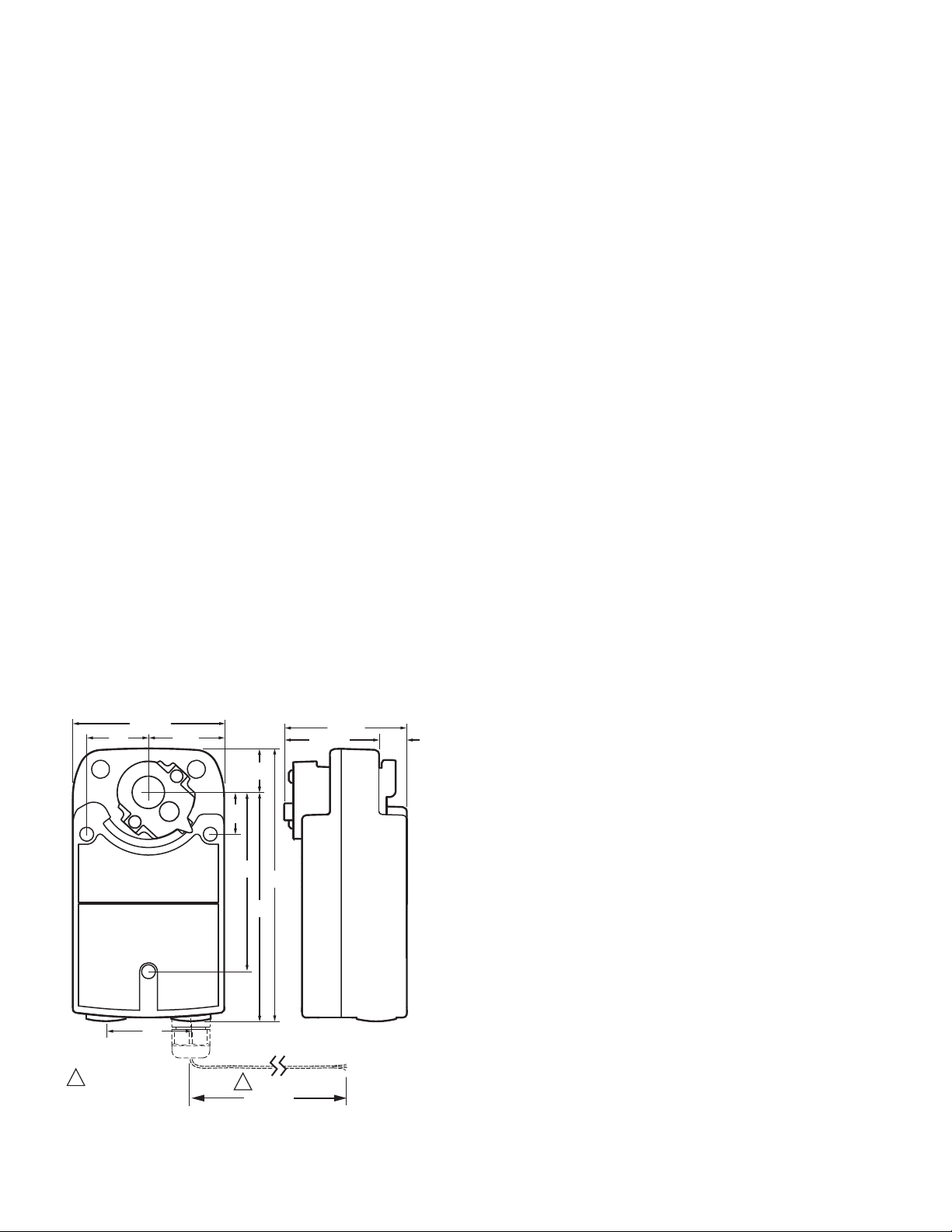
If the coupling must be moved from one side of the actuator to
the other, reverse the spring return direction and flip the
actuator. Follow these instructions (see Fig. 3):
1. Remove the retainer clip from the shaft coupling and set
it aside for later use.
2. Remove shaft coupling from one side of the actuator.
3. Replace the shaft coupling on the opposite side of the
actuator aligning it based on the stroke labeling.
4. Replace the retainer clip on the shaft coupling using the
groove of the coupling.
M27714
Fig. 3. Mounting shaft coupling to actuator opposite side.
Selecting Actuator Control Signal
Selections are made using a dial that appears on both the
front and back of the actuator (see Fig. 4).
SELECT SWITCH POSITION
For switch models, select the degree of rotation you want the
switch to activate.
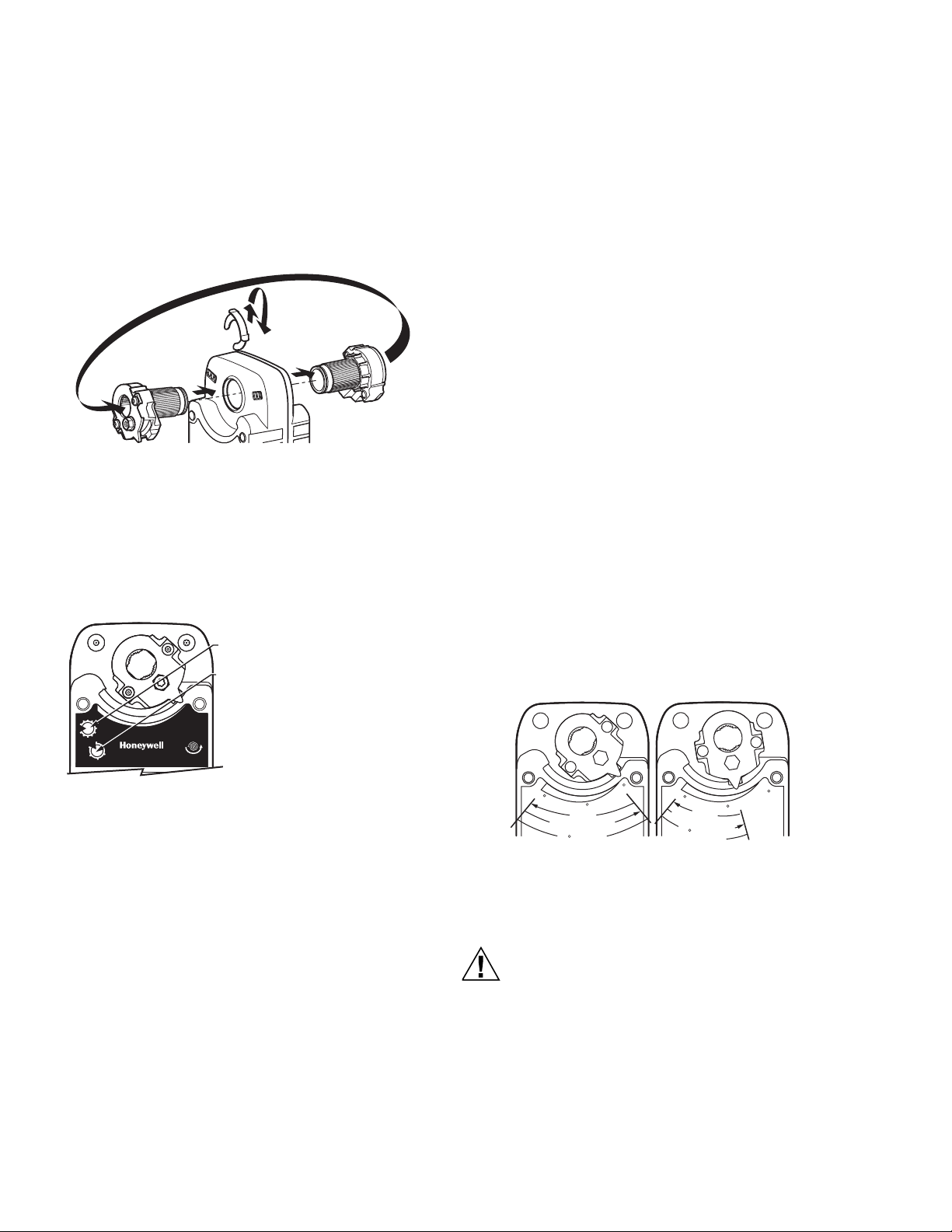
Non-Standard Stroke
Mechanical Stroke Limit Reduction
For applications requiring a span less than 95 degrees, a
simple adjustment can be made. When the rotational
mounting of the shaft coupling is changed, the actuator drives
less than the full 90 degrees stroke.
The stroke is adjustable in 5 degree increments. Once
adjusted, the actuator drives until the shaft coupling reaches
the mechanical stop (part of the housing). The stop causes
the motor to discontinue driving and the shaft coupling drives
no farther. When the actuator returns, it stops at the fail-safe
position.
To limit the stroke range, proceed as follows:
1. Remove the retainer clip from the shaft coupling and set
it aside for later use.
2. Remove shaft coupling from the actuator.
3. Rotate the coupling to the desired position, aligning it
based on the stroke labelling. See Fig. 5.
NOTE: The shaft coupling location determines the
travel span.
To select the control signal simply turn the mode selection dial
to the desired mode (as indicated on the device label) without
exceeding range indicators.
Fig. 4. Dials for control signal and switch or minimum
position.
Auxiliary Knob
The auxiliary knob can be used to control minimum position
(MS74 Series) or switch position.
SELECT MINIMUM POSITION (MS74 SERIES)
To set the actuator minimum position, turn the AUX dial to the
desired position. Alternatively, minimum position can be set
with an externally connected 1kOhm potentiometer connected
across common (terminal 2) and minimum position (terminal
4); the setting on the AUX dial will be overridden.
EXAMPLE:Setting shaft coupling to an approximate
fail-safe position of 35 degrees (as indicated
on the housing) limits stroke to 60 degrees.
(See Fig. 5)
4. Install the shaft coupling at this position.
5. Replace the retainer clip on the shaft coupling using the
groove of the coupling.
0
90
45
D
E
R
I
V
S
P
R
9
N
R
I
U
N
T
G
E
R
0
E
K
S
O
T
R
90
45
6
D
S
R
I
V
E
P
R
I
N
G
R
E
6
T
U
R
0
S
T
R
O
K
E
0
N
M27716
Fig. 5. Stroke reduction.
Mounting
Device Malfunction Hazard.
Improper shaft coupling tightening causes device
malfunction.
Tighten shaft coupling with proper torque to prevent
damper shaft slippage.
62-0274—07 4
 Loading...