

Page 1
IInntteelllliiPPaatth
h
M
TTM
SSeerriieess CCoommmmuunniiccaattoorr
LLTTEE--C
LLTTEE--C
CCoommmmeerrcciiaall FFiirree PPaanneell IInntteerrnneett aanndd CCeelllluullaarr CCoommmmuunni
CFFVV
CFF
A
A
iccaattoorr
Installation and Setup Guide
800-24454 9/18 Rev A
Page 2

Page 3

Table of Contents
SECTION 1: General Information ..................................................................................................................... 1
System Overview .......................................................................................................................................... 1
Introduction ............................................................................................................................................ 1
General Information ............................................................................................................................... 1
System Features ........................................................................................................................................... 2
About AlarmNet-i Internet Application .......................................................................................................... 2
Encryption ..................................................................................................................................................... 2
Operation ...................................................................................................................................................... 2
Supervision Features .................................................................................................................................... 2
Specifications ................................................................................................................................................ 3
Compatibility ................................................................................................................................................. 4
Compliance ................................................................................................................................................... 4
SECTION 2: Mounting and Wiring ................................................................................................................... 5
Determine the Signal Quality and Select a Location .................................................................................... 5
Mount the Communicator ............................................................................................................................. 6
Wire the Communicator ................................................................................................................................ 7
Wire the Internet Connection ........................................................................................................................ 8
Power Up the Communicator ....................................................................................................................... 8
SECTION 3: Programming the Communicator............................................................................................... 9
General Information ...................................................................................................................................... 9
Programming the Control Panel to work with the LTE-CF ..................................................................... 9
Programming for UL864 Compliance ................................................................................................... 10
Using the AlarmNet 360 Website ......................................................................................................... 10
Using a 7720P Programming Tool ....................................................................................................... 11
Using the Control Panel Programming Mode ...................................................................................... 11
Programming Conventions .................................................................................................................. 12
Programming .............................................................................................................................................. 12
Exiting Programming Mode ........................................................................................................................ 15
Setting Factory Defaults ............................................................................................................................. 15
SECTION 4: Registration ................................................................................................................................ 17
Registering the Communicator ................................................................................................................... 17
Registering through the AlarmNet 360 Website .................................................................................. 17
Register using the TEST / REGISTRATION Switch ............................................................................ 18
Register using the Programming Tool ................................................................................................. 18
Replacing an existing communicator ................................................................................................... 19
Register by Phone ................................................................................................................................ 19
i
Page 4

LTE-CF Installation and Setup Guide
SECTION 5: Programmer Keyboard Commands ......................................................................................... 21
Identification Displays ................................................................................................................................. 21
Cell Status Displays .................................................................................................................................... 22
System Status Display ................................................................................................................................ 25
SECTION 6: Network Diagnostics ................................................................................................................. 27
Running Network Diagnostics .................................................................................................................... 27
Possible Errors Running Network Diagnostics ........................................................................................... 28
Appendices ..................................................................................................................................................... A-1
Appendix A : Summary of LED Operation ................................................................................................. A-1
Appendix B : Central Station Messages .................................................................................................... B-1
Appendix C : Glossary ............................................................................................................................... C-1
Wiring Diagram………………………………………………………………………………..………………...Inside Back Cover
ii
Page 5

SECTION 1
General Information
System Overview
Introduction
Congratulations on your purchase of Honeywell's LTE-CFV/LTE-CFA Commercial Fire Panel
Internet and LTE Communicator (henceforth referred to as LTE-CF). It represents the latest and
most innovative communication technology for the security industry and uses the most
sophisticated encryption to ensure the highest level of security for your customer.
The new cellular connectivity brings faster cellular data transfers with lower latency (response
time); together it results in speedier data transfers.
This communicator uses the Internet as its primary reporting path, and switches to cell service
(secondary path as backup) when the Internet is not available.
The communicator requires an AlarmNet–i account. For new installations, please obtain
the account information from the central station prior to programming this communicator.
For detailed information about enrolling the communicator and replacing communicators,
refer to the AlarmNet 360 Online Help Guide.
In addition to alarm reporting, the communicator provides upload/downloading capability of
Honeywell's control panel data over the Internet, using cellular technology.
UL
General Information
The LTE-CF communicates via the Internet (when service is available) and switches to cellular
(here-in known as “cell”) service when the Internet is not available.
In normal operation (with Internet connectivity), the LTE-CF communicates from your customer's
network connection to the Honeywell Network Operations Center, (NOC) via the AlarmNet-i
network. The NOC receives data and routes the information to the Central Station of your choice,
based on the account number you assign to the communicator. Note that your Central Station
needs to give you the account number. The same account number is used for both Internet and
cell transmissions. If your current Central Station is capable of receiving signals from the
Honeywell NOC, they are capable of receiving signals from the communicator.
If, for some reason, Internet connectivity is not available, (for example, your customer's ISP is off
line or disconnected), the communicator will transmit signals via the cellular network. These
transmissions are sent to the Honeywell NOC and then forwarded to your Central Station exactly
the same way as if they were received via the Internet.
If the Internet and Cell network are both unavailable (fail), the message will not be sent from this
communicator.
When performing remote downloading, a technician must be on-site to test the system after any
programming is changed.
For maximum reliability, it is recommended the device be operated in dual path
mode with Internet and Cell both enabled and connected.
1
Page 6

System Features
Basic features include:
Supports dynamic or static IP addressing, and installs behind firewalls without compromising
network security.
Quick connection to compatible Honeywell series control panels.
Simple programming using a 7720P programming tool.
Reports fire and status messages via the Internet.
Reports messages via the Internet and uses Cellular as backup.
Allows uploading and downloading of control panel data over the Internet.
(UL: A technician must be on-site to test the system after any programming is changed.)
About AlarmNet-i Internet Application
AlarmNet-i is a fully encrypted, secure method of delivering alarm messages from a protected
premise to an AlarmNet equipped central station. The internet communicator transmits status,
supervisory, and alarm messages to the AlarmNet Control Center using a broadband Internet
connection.
The AlarmNet Control Center identifies, validates, and forwards the messages to the appropriate
AlarmNet central station. AlarmNet-i has an unlimited account capacity.
Encryption
The communicator uses 256 bit AES (Rijndael) encryption (which is required for certain
government installations). The AlarmNet-i AES Encryption Software Module Version 1.0
contained in the Honeywell products has NIST approval. Listings for this approval can be found
at https://csrc.nist.gov/projects/cryptographic-algorithm-validation-program/validation/validationlist/aes and search for “Certification number 979.”
LTE-CF Installation and Setup Guide
UL
Operation
The communicator interfaces with the control panel using Honeywell’s ECP bus.
Used with any UL Listed control panel that supports ECP communication.
The communicator connects to the control panel’s keypad terminals and provides 2-way
communication with the control panel using ECP messaging.
The control panel treats the communicator as an ECP device, so ensure to program the
control panel with the communicator’s device address.
Supervision Features
Reports are sent in Contact ID format.
The communicator provides the following types of supervision and fault detection:
Network communication failure: In the event the AlarmNet network does not hear a
supervisory message from the communicator within a specified time, AlarmNet notifies the
central station of a communication failure.
Communication path failure: In the event the module detects a communication path failure,
both the Central Station and the control panel can be notified of the trouble condition. Both
failures are considered true faults when their fault times have expired. If the Internet or Cell
communications path fails, a message is reported.
Primary power loss and low battery conditions (detected by the control panel, and may be
reported via the communicator if programmed to do so).
The IP and Cell signaling paths are suitable for encrypted line security. The system
configurations are not suitable as a Dual Line Signal transmission system.
2
Page 7

Section 1: General Information
Specifications
Mechanical:
Input Power:
Dimensions: 15.0"H x 12.75" W x 3.0" D
Weight: 10 lbs.
12VDC supplied by the Control Panel.
Current Drain:
Ethernet:
90mA (rms) standby, 105mA (rms) active
Network Standard: IEEE 802.3u compliant
Data Rate: 10Base-T / 100Base-T with auto detect
Ethernet Cable: Cat. 5 (min), MDI / MDI-X auto crossover
Environmental:
Operating temperature: 0ºC to +49ºC
Storage temperature: –40º to +70ºC
Humidity: 0 to 85% relative humidity, non-condensing
Altitude: to 10,000 ft. operating, to 40,000 ft. storage
Frequency Bands
LTE-CFV X X X
LTE-CFA X X X X X X X
Output Power
LTE, Class 3 23dBm
WCDMA Class 3 24dBm
LTE
Band 2
LTE
Band 4
LTE
Band 5
LTE
Band 12
LTE
Band 13
WCDMA
Band II
WCDMA
Band V
3
Page 8

Compatibility
LTE-CF Installation and Setup Guide
UL – Compatible Control Panels
VISTA-32FB FA1670C (First Alert)
VISTA-32FBT FA1670CT (First Alert)
VISTA-128FBP FA1700C (First Alert)
VISTA-128FBPT FA1700CT (First Alert)
VISTA-250FBP
VISTA-250BPT
UL – Compatible Receivers
7810iR-ENT Must be the primary alarm receiver.
8810iR Must be the primary alarm receiver.
MX8000 Can be used for supplemental reporting in ECP mode when connected to
model 7810iR-ENT.
Compliance
Ademco 685 Can be used for supplemental reporting in ECP mode when connected to
model 7810iR-ENT.
7810PC Must be the primary alarm receiver
UL
The Automation System must be UL1981 listed.
To meet UL864/NFPA, ensure the following:
It must be installed in accordance with NFPA (National Fire Protection Association)
standards 70 and 72.
It must be mounted in the same room and within 20 feet of the fire panel.
Conduit is required for all interconnections between the Fire Panel and communicator.
All equipment used for the IP connection (such as the router, hub, modem, etc.) shall be
listed, must be powered from an un-switched branch circuit, and be provided with
appropriate standby power.
4
Page 9

SECTION 2
Mounting and Wiring
Determine the Signal Quality and Select a Location
The communicator must be mounted indoors within the protected premises. When choosing a
suitable mounting location, understand that signal strength is very important for proper operation.
For most installations using the supplied antenna, mounting the unit as high as practical, and
avoiding large metal components provides adequate signal strength for proper operation.
In this procedure, you will use the communicator to determine signal strength to find a suitable
mounting location.
RF Exposure
Warning – The internal or external antenna(s) used with this product must be installed to
provide a separation distance of at least 7.8 in. (20 cm) from all persons and must not be colocated or operating in conjunction with any other antenna or transmitter except in accordance
with FCC multi-transmitter product procedures.
* LTE-CF Initial Power Up: Upon initial power up, the communicator LEDs blink in repeated
sequence from top to bottom indicating network initialization.
Green (REG) Yellow (TX/RX) Red (FAULT)
This sequence may take up to 15 minutes. Do not reset power during this time.
When initialization is complete, the Signal Quality display LEDs will light and the yellow and
red LEDs may blink (per their respective functions).
After initial network setup, subsequent resets or power ups can take up to 90 seconds.
1. For this procedure, you will need a fully charged 6V battery.
2. Attach the two Antenna Mounting Adapters, two RF cable, and two Antennas. Remove the
top knockout if necessary. Refer to the Wiring Diagram on the inside of the back cover for
wiring and component identification.
3. Temporarily connect the battery to the communicator (Jumper wire between TB1 pins 2 and
3, Battery Positive on TB1 pin 3, and Battery Negative on TB1 pin 4). Wait about one minute
for the communicator to initialize.
4. Position the assembly near a suitable mounting position and observe the signal quality
display. Choose a location with the best signal strength by observing the signal quality bar
graph (refer to Appendix A for information about signal quality and status indications).
Signal quality should be within 2-5 bars lit solid. For optimal performance 4 or 5 bars are
better. The best signal strength is usually found at the highest point in the building, near a
window.
5. Verify the signal strength remains steady for a few minutes, then mark that mounting position.
Disconnect the battery.
5
Page 10

Mount the Communicator
This communicator comes fully assembled with all the components mounted except the external
Antenna, and Antenna Mounting Adapter.
Refer to the Wiring Diagram on the inside of the back cover for wiring and component
identification.
For UL compliant installations, refer to the topic on Compliance in Section 1 of this manual.
For Dry/Indoor use only.
Unless otherwise specified, use 18AWG.
Installation must be in accordance with the National Fire Alarm and Signaling Code,
ANSI / NFPA 72.
1. Remove knockouts from cabinet to accommodate the wiring to the control panel, and internet
connection to a router. Then mount the cabinet securely to the wall using 4 screws or bolts.
Use mounting screws or bolts that are suitable for the material being anchored to.
2. Ensure the cabinet door lock is installed.
3. Connect and route 16AWG (minimum) insulated wire from facility power ground (typically a
cold-water pipe) to the cabinet's ground post. Ensure all ground connections are tight.
4. Ensure the following:
All wiring terminals and connectors are tight.
All wiring has been completed and secured with cable ties.
5. When the communicator wiring and programming (next section) is complete, lock the cabinet.
LTE-CF Installation and Setup Guide
6
Page 11
Section 2: Mounting and Wiring
Wire the Communicator
UL
Installation must be in accordance with; the National Electrical Code.
The communicator must be connected to a UL Listed compatible control panel.
All interconnecting wires between the UL Listed control panel and the communicator must be less
than 20 feet in length contained in the same room. All interconnecting wiring must be installed in rigid
metal conduit or EMT (Electrical Metallic Tubing) where exposed on interior walls; or in flexible metal
tubing if run in the walls or ceiling.
All equipment used for the IP connection (such as the router, hub, modem, etc.) shall be listed, must
be powered from an un-switched branch circuit, and be provided with appropriate standby power.
A UL listed control panel must monitor the radio fault output of the communicator.
Most Honeywell control panels support ECP data communication. Check the Installation and
Setup Guide for the control panel you are using to see if it supports ECP communication.
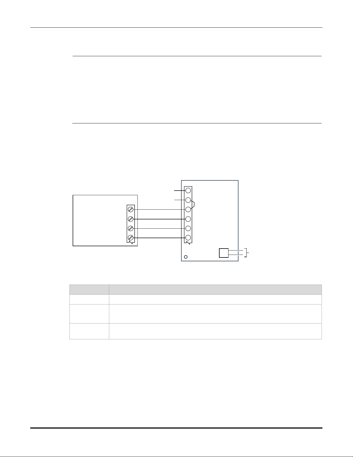
The communicator’s ECP wiring will be in parallel with keypads and other peripheral devices such
as RF receiver, etc., of the control panel. Wire length/gauge limitations are the same for the
communicator as they are for keypads and other peripheral devices. To wire the communicator,
see the figure below and make the following connections:
TB1
AC INPUT 1
1
AC INPUT 2
2
ECP (+) VOLTAGE INPUT
3
GND
4
5
ECP DATA IN
6
ECP DATA OUT
J1
NO CONNECTION
CONTROL PANEL
+12 V AUX
GND
DATA OUT
DATA IN
NO CONNECTION
NO CONNECTION
RED
BLK
YEL
GRN
COMMUNICATOR
IGSMCFP4G-013-V1
Item Notes
Wiring
UL: Use minimum 18AWG wire.
Power The communicator is powered from the control panel.
Ensure a jumper is installed between TB1 pins 2 and 3.
ECP data The control panel treats the communicator as an ECP device, so ensure to program the
control panel with the communicator’s device address.
7
Page 12
Wire the Internet Connection
For UL installations, the Ethernet connection between the communicator and the router can-
not exceed 20 feet with both the communicator and the router located within the same room.
UL
All equipment used for the IP connection (such as the router, hub, modem, etc.) shall be
listed, must be powered from an un-switched branch circuit, and be provided with appropriate
standby power.
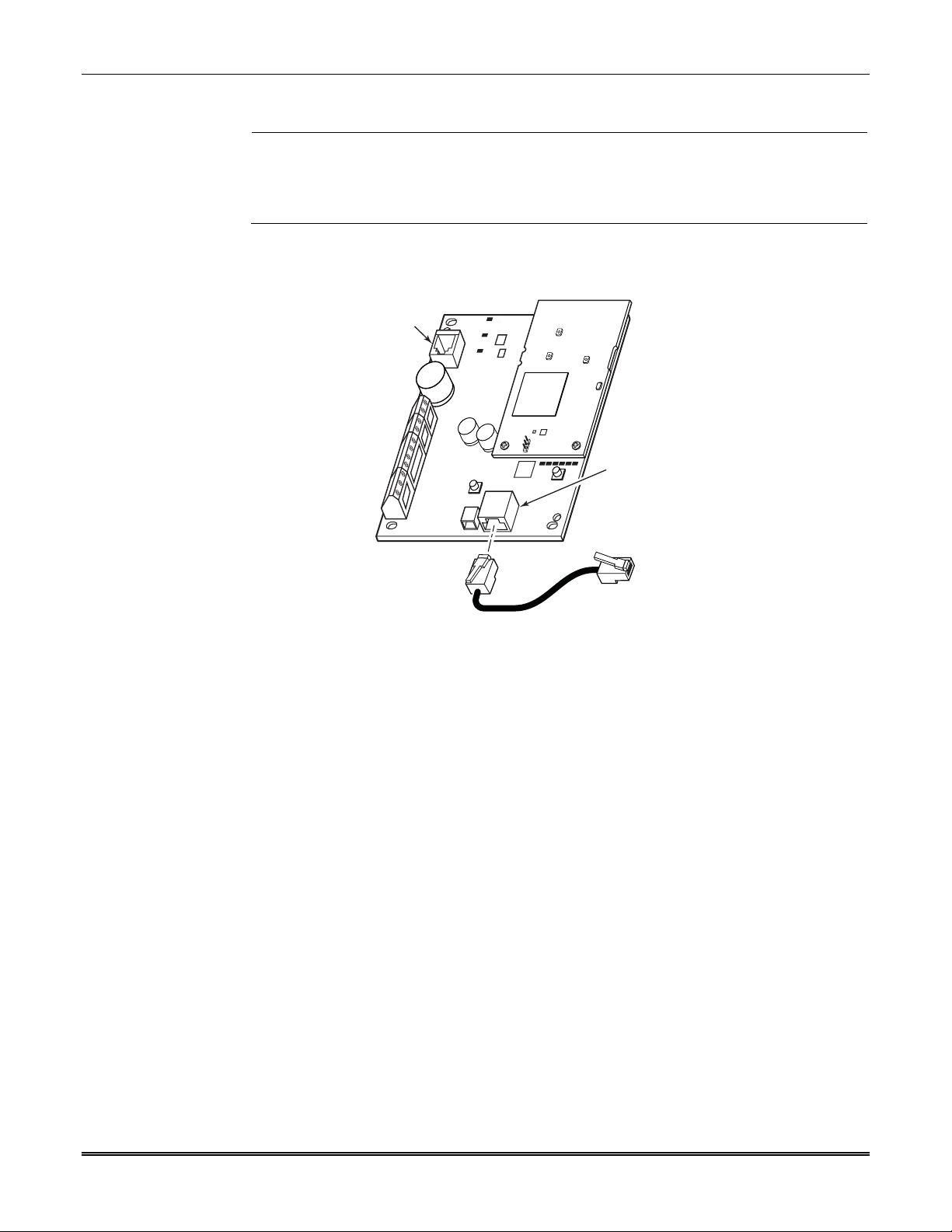
Connect one end of the Ethernet cable to the communicator’s RJ45 Ethernet connector and the
other end to the cable / DSL router as shown in the figure below.
7720P
PROGRAM
CONNECTOR
LTE-CF Installation and Setup Guide
RJ45
(FOR INTERNET
CONNECTION)
Power Up the Communicator
Power up the control panel. (Initially, all communicator programming options are set to the
factory default settings.)
TO ROUTER
LTE-CF-001-V1
8
Page 13

SECTION 3
Programming the Communicator
General Information
The communicator is designed to deliver alarms via the Internet to an AlarmNet central station or
via the cellular network when the Internet is not available.
NOTE: Out of the box, all communicator programming options are set to the factory default
settings.
The communicator requires an AlarmNet–I account. For new installations, please obtain the
account information from the central station prior to programming this communicator. For
replacement installations, the AlarmNet-i account is created automatically when the commu-
You can program a communicator by one of the following methods:
Through the AlarmNet 360 website
Through use of a 7720P Programming Tool
Through a programming mode in the control panel, on panels that support this option
nicator is registered.
(UL: A technician must be on-site to test the system after any programming is changed.)
Programming the Control Panel to work with the LTE-CF
For Commercial control panels, there are certain programming field settings that must be adhered
to for using the communicator. (For programming information, please refer to the appropriate
control panel guides.) Ensure the following programming fields are set:
COMMERCIAL Control Panels
UL: For compatible control panels, refer to the “Compatibility” topic in section 1.
Programming Field Setting
32 Primary Subscriber's Acct No. nnnn (Required for the communicator to report.)
56 Dynamic Signaling Delay 00 (Dialer and LRR reports go out at the same time.)
57 Dynamic Signaling Priority 1 (Communicator, as first reporting.)
58 Comm Central Station #1
Category Enable
59 Comm Central Station #2
Category Enable
#93 Menu Mode Zone programming – set Zone 803 for Type 05.
111111 (All events will be reported to the primary Central
Station.)
000000 (If Central Station #2 is not used.)
111111 (If Central Station #2 is used.)
Device programming – set Address 03 for Type 06 (LRR).
9
Page 14

LTE-CF Installation and Setup Guide
Programming for UL864 Compliance
This communicator provides a programmable supervision feature that allows the system to meet
the UL864 Commercial Fire requirements. These requirements are in the following table.
NOTICE TO USERS, INSTALLERS, AUTHORITIES HAVING JURISDICTION AND OTHER INVOLVED PARTIES
This product incorporates field programmable software. In order to comply with the requirements in the standard for
control units and accessories for Fire Alarm Systems, UL 864 certain programming features or options must be limited to
specific settings or not used at all as indicated below.
Selected Com. Path Supervision Interval IP Fault Time Cell Fault Time UL864 Compliant?
2010 Cell 5 minutes N/A 5 minutes
2010 IP 5 minutes 5 minutes N/A
2010 IP & Cell 24 hours 1 hour 1 hour
2013 Cell 1 hour N/A 1 hour N
2013 IP 1 hour 1 hour N/A N
2013 IP & Cell 6 hours 1 hour 1 hour N
Y
Y
Y
Only the indicated setting is compliant. Any other value in this field will not meet UL864 Commercial Fire
requirements.
Using the AlarmNet 360 Website
To program the communicator via the website (if you are already signed up for this service), go
to: www.alarmnet60.com
UL
When performing remote downloading, a technician must be on-site to test the system after any
programming is changed.
Log in and follow the on-screen prompts.
Please have the following information available when programming the communicator:
1. Primary City ID (two-digit number)
2. Primary Central Station ID (two-digit hexadecimal number)
3. Primary Subscriber ID (four-digit number)
4. MAC ID and MAC CRC number (located on the box and inside the communicator)
After programming is complete, you must transfer the data to the communicator and the
communicator must be registered. Refer to Section 4: Registration, for further instructions.
10
Page 15

Section 3: Programming the Communicator
Using a 7720P Programming Tool
Connect the 7720P Programming Tool as shown below. The communicator powers the 7720P
Programming Tool via the programming jack, and automatically senses the presence of the
7720P when it is plugged in.
Each key of the 7720P has two possible functions: a normal function and a Shift function.
To perform a normal key function, simply press the desired key.
To perform a Shift function, press the [shift] key, and then press the appropriate key.
The prompts in this document reflect use of the 7720P Programming Tool. The table below lists
each normal and shift key function.
7720P Normal and Shift Key (shift LED lit) Functions
KEY NORMAL KEY FUNCTION SHIFT KEY FUNCTION
BS / ESC [BS]: Press to delete entry
/ []: Scroll down programming []: Scroll up programming
N / Y [N]: Press for "NO" answer [Y]: Press SHIFT-Y for "YES" answer
SHIFT
Press before pressing a SHIFT key function. Will light SHIFT LED. LED goes out once a key
is pressed. Press again for each SHIFT function desired.
1 / A [1]: For entering the number 1 [A]: For entering letter A
2 / B [2]: For entering the number 2 [B]: For entering letter B
3 / C [3]: For entering the number 3 [C]: For entering letter C
4 / D [4]: For entering the number 4 [D]: For entering letter D
5 / E [5]: For entering the number 5 [E]: For entering letter E
6 / F [6]: For entering the number 6 [F]: For entering letter F
7 / S [7]: For entering the number 7 [S]: For entering letter S
8 / T [8]: For entering the number 8 [T]: For entering letter T
9 / X [9]: For entering the number 9 [X]: For entering letter X
SPACE [SPACE]: For scrolling option list No SHIFT function
0 [0]: For entering the number 0 No SHIFT function
# / ENTER
[#/ENTER]: Starts programming mode;
Press to accept entries
* Active only when the "Exit Programming Mode" prompt is displayed.
7720P
PROGRAM
CONNECTOR
Xmit
Shift
7720 PROGRAMMING TOOL
A
B
BS / ESC
/
N / Y
Shift
Space Enter
123
DE
45
S
7
C
F
6
T
X
98
#0
7720P Programming Tool Connection
[ESC]: Press to quit program mode; also can reset
programming defaults*
No SHIFT function
LTE-CF-002-V1
Using the Control Panel Programming Mode
Most control panels support programming of the communicator through the control panel
programming mode (refer to the control panel’s installation guide). If programming through the
control panel, only the ECP Mode programming options are available. The "mode" prompts will
not be displayed, and the mode cannot be changed. For a description of key functions on the
control panel keypad, and how they map to the 7720P Programming tool, refer to the control
panel's Programming Guide.
11
Page 16

LTE-CF Installation and Setup Guide
Programming Conventions
Programming is accomplished by answering a series of prompts. Most prompts require only a
[Y]es or [N]o response, while others require a numerical response (ID numbers, etc.).
The current value is displayed on the second line in parentheses ( ). A "?" indicates an invalid
entry.
Use the [ENTER] key to accept the current entry and proceed to the next prompt. If the entered
value is invalid, pressing [ENTER] re-displays the prompt; the next prompt is not displayed until a
valid answer is entered.
Use the up
values. Press the [ESC] key to go to the end of the list of prompts.
Programming
The communicator supports ECP messaging via the control panel’s ECP bus. These messages
are in Contact ID format. (Not all control panels support the ECP bus, so be sure to check the
control panel’s Installation and Setup Guide to see if it supports this feature.)
Press the [ENTER] key to begin programming.
PROMPTS OPTIONS DESCRIPTION
Strt Prog Mode?
1
(Y/N)_
Enter Password:
2
Program Device?
3
(Y/N)_
Create Password?
4
(Y/N)_
Change
5
Password? (Y/N)_
Enter Password
6
Verify Password
7
/ down arrow keys to scroll through the programming prompts without changing any
NOTE: The central station can remotely block access to local device
programming. If this has been done, the following prompt appears:
Programming the communicator
[Y], [N]
[0-9, A-F, N, S, T,
X, Y]
[Y], [N ]
[Y], [N]
[Y], [N]
[0-9, A-F, N, S, T,
X, Y]
[0-9, A-F, N, S, T,
X, Y]
Enters programming mode.
If a password has been previously assigned, this prompt appears.
Enter a 4-digit password (0-9, A-F, N, S, T, X, Y).
The next prompt appears.
To begin programming the communicator, press [Y] and go to Prompt
10: "Device Mode."
To create a password if none has been assigned, press [N] and go to
Prompt 4: "Create Password."
To change an existing password, press [N] and go to Prompt 5:
"Change Password."
Passwords can be used to protect account and programming
information.
If no password has been assigned, this prompt appears after pressing
[N] at the "Program Device?" prompt.
If a password is desired, press [Y] and go to "Enter Password."
If a password has already been assigned, this prompt appears after
pressing [N] at the "Program Device?" prompt.
Press [Y] if you want to change the password.
NOTE: To clear an existing password, without entering a new one,
answer [Y] to the "Change Password?" prompt, then press the [Enter]
key when prompted for the new password and its confirmation.
This prompt is displayed if [Y] was pressed in Prompt 4 or 5.
Enter a 4-digit password (0-9, A-F, N, S, T, X, Y).
Re-enter the password as confirmation.
If the password doesn't match the first entry, the following is displayed
followed by the "Exit Prog. Mode?" prompt:
Verify Not OK
PSWD not created
Otherwise, the "Exit Prog. Mode?" prompt is displayed directly.
Access to Prog
Mode Denied
12
Page 17

Section 3: Programming the Communicator
PROMPTS OPTIONS DESCRIPTION
Exit Prog. Mode?
8
(Y/N)_
Comm Path
9
Choice
(2010 IP & Cell)_
NOTE: Account information is provided by the central station administrator. (Prompts 10-12)
Primary City ID
10
(??)_
11
Primary CS ID
(??)
12
Primary Sub ID
(????)
[Y], [N]
[ESC]
2010 IP & Cell
2013 IP
2013 Cell
2013 IP & Cell
2010 IP
2010 Cell
The settings that correspond to the choices are:
Choice Supervision Interval IP Fault Time Cell Fault Time
2010 IP & Cell 24 hours 1 hour 1 hour
2013 IP 1 hour 1 hour - - 2013 Cell 1 hour - - - 1 hour
2013 IP & Cell 6 hours 1 hour 1 hour
2010 IP 5 minutes 5 minutes - - 2010 Cell 5 minutes - - - 5 minutes
[01-99]
[01-FE]
[0001-9999]
Exits program mode.
Press [N] to go back to Prompt 3.
Press [ESC] to load factory defaults.
Refer to the Exiting Programming Mode paragraph in this section.
The Comm Path Choice option is a dual-purposed option. The
selection sets the Comm Paths available to the communicator as well
as the supervision interval and fault times necessary to comply with
the selected edition of the NFPA72 standard.
The two editions of the standard are 2010 and 2013.
The AlarmNet network must hear at least one message from the
device during this supervision period; otherwise, AlarmNet notifies the
central station that a communication failure occurred. This interval
cannot be changed.
Enter the 2-digit primary city ID, 01-99 (decimal).
Enter the 2-digit primary central station ID number, 01-FE (HEX).
Enter the 4-digit subscriber account number, 0001-9999 (decimal).
NOTE: Prompts 13 through 17 only appear if the Comm Path Choice is IP, or IP&Cell.
13
IP Flt Time
(60 mins)
NOTE: Refer to table above for
correct default values.
[00-60]
This prompt appears only if comm. path includes IP&Cell or IP.
Enter the time delay (1 – 60) in minutes before the
communicator notifies the control there is a communication
path failure over cell. If the panel has an alternate
communication path, a secondary path loss message is sent to
the central station.
13
Page 18

LTE-CF Installation and Setup Guide
PROMPTS OPTIONS DESCRIPTION
14
Cell Flt Time
(60 mins)
[00-60]
This prompt appears only if comm. path includes IP&Cell or Cell.
Enter the time delay (1 – 60) in minutes before the communicator
notifies the control panel that there is a communication path failure to
AlarmNet over the hard-wired Ethernet connection. If the panel has an
NOTE: Refer to table above for
correct default values.
NOTES:
alternate communication path, a primary path loss message is sent to
the central station.
Changing the IP and Cell comm. path choice defaults the value according to the table in prompt 5.
The control is notified of the failure after the Cell and/or IP fault times expire.
Use DHCP Y/N
15
(Y)_
NIC IP Address:
16
255.255.255.255_
Subnet Mask:
17
255.255.255.255_
Gateway IP Addr:
18
255.255.255.255_
DNS Serv IP Addr:
19
255.255.255.255_
Review? Y/N
20
[Y], [N]
12 digit:
xxx.xxx.xxx.xxx
12 digit:
xxx.xxx.xxx.xxx
12 digit:
xxx.xxx.xxx.xxx
12 digit:
xxx.xxx.xxx.xxx
[Y] = review
[N] = exit
Dynamically allocates the IP addresses (recommended).
If [N], uses fixed IP addresses.
Enter the 4-part address for this device. The 4 parts of the address
must be separated by spaces (displayed as periods in Review mode).
Enter the 32-bit address mask used to indicate the portion (bits) of the
IP address that is being used for the subnet address. The 4 parts of
the address must be separated by spaces (displayed as periods in
Review mode).
Enter the 4-part address assigned to the Gateway. The 4 parts of the
address must be separated by spaces (displayed as periods in Review
mode).
Enter the 4-part IP address assigned to the DNS (Domain Name
System) server. The 4 parts of the address must be separated by
spaces (displayed as periods in Review mode).
Reviewing Programming Mode Entries
To review the programming options (to ensure that the correct entries
have been made), press [Y]. The programming prompts are displayed
again. Use the up/down arrow keys to scroll through the program
fields without changing any of the values. If a value requires change,
simply type in the correct value.
When the last field is displayed, the “REVIEW?” prompt again
appears.
To exit the programming mode, press [N] in response to the
"REVIEW?" prompt, and refer to Exiting Programming Mode at the
end of this section.
14
Page 19

Section 3: Programming the Communicator
Exiting Programming Mode
To exit the programming mode, press [N] in response to the "REVIEW?" prompt. Then press [Y]
to the "Exit Prog Mode?" prompt. Upon exiting, the root file is updated to log the changes made.
A message is displayed telling the user that this step is being executed. When complete, the
message "DONE" is displayed to indicate the file was successfully uploaded.
If critical configuration changes were made, such as the mode of operation, the communicator
will reset to ensure that the programming features are enabled.
If the file is not successfully uploaded, one of the following prompts will be displayed. Follow the
steps shown below until the upload is successful.
Display Description What to do
Cannot Upload
Try Again? Y/N_
Failed to Update
Root File!
Communicator is not yet initialized. Wait for RSSI LEDs to be lit.
Network problem, or you answered
"N" to "Cannot Upload Try Again?"
prompt.
Press [Y].
Initiate the Force Server Update
Command by pressing the [0] key; refer to
Section 5: Programmer Keyboard
Commands.
Setting Factory Defaults
To reset the programming options to factory-default values, press [ESC] at the "Exit Prog Mode?"
prompt.
Set Default?
Y/N_
If you press [Y], all programmed values are reset to the original factory settings. PLEASE NOTE
THAT THIS WILL ERASE ANY PASSWORD THAT MAY HAVE BEEN ENTERED. After pressing
[Y], the Create Password prompt appears (see Prompt 4).
Press [Y] to reset factory default values.
Press [N] to cancel this function.
15
Page 20

16 . 17
Page 21

SECTION 4
Registration
Registering the Communicator
Once you have programmed the communicator, it must be registered to enable the AlarmNet
account. Registering the communicator activates the account with AlarmNet and enables the
security system's control panel to send reports. You can register by using one of the following
methods:
AlarmNet 360 website 7720P Programming Tool
Test Message
/ Registration switch Phone
LED DESCRIPTION
STATUS
(green)
MESSAGE
(yellow)
FAULT
(red)
ON – Is NOT registered with AlarmNet.
OFF – Is registered with AlarmNet.
ON – Message transmission pending.
QUICK PERIODIC BLINK - Normal
SLOW BLINK – In unison with green LED,
Registration in progress.
OFF – No fault present.
You can monitor the registration process by viewing the display LEDs. The TX/RX (yellow) LED
and the REG (green) LED will blink slowly in unison while registration is in progress.
When the registration successfully completes, the communicator enters a normal operating
mode; the REG (green) LED goes out and the TX/RX (yellow) LED is lit to indicate that the
power-on / reset message is waiting to be sent. This message will appear at the receiving
station as “E339 803”. The description may read “Trouble – Exp. Mod. Reset”. If registration is
not validated within 90 seconds, the communicator times out, and the REG (green) LED will be
lit solid.
Registering through the AlarmNet 360 Website
To register the communicator via the website, go to: AlarmNet360.com
Log in and follow the on-screen prompts.
Please have the following information available:
Primary City ID (two-digit number).
Primary Central Station ID (two-digit hexadecimal number).
Primary Subscriber ID (four-digit number).
MAC ID and MAC CRC number (located on the box and inside the communicator).
After the communicator is registered, you may log out of the AlarmNet 360 website.
STATUS
MESSAGE
FAULT
Page 22

LTE-CF Installation and Setup Guide
Register using the TEST / REGISTRATION Switch
Initiate the registration sequence by clicking the TEST
/ REGISTRATION switch three times.
You can monitor the registration process by viewing the Status Display. The Message (yellow)
LED and the Status (green) LED will blink slowly in unison while registration is in progress.
Once the registration has been completed successfully, the communicator enters normal
operating mode; the Status (green) LED goes out and the Message (yellow) LED is lit to indicate
that the Power On / Reset message is waiting to be sent. This message will appear at the
receiving station as “E339 C08xx”, where “xx” is the ECP device address. The description may
read “Trouble – Exp. Mod. Reset”. If registration is not validated within 90 seconds, the
communicator times out, and the (green) LED will be lit (solid).
If repeated registration attempts time out, check your Internet connection and RSSI level, and
verify the account information has been entered correctly.
Register using the Programming Tool
The interactive registration feature allows the installer to register the communicator through a
series of keyboard commands on the 7720P Programming Tool. This method of registration lets
the installer monitor the registration process.
Registering …
Once the installation is complete, press the [Shift] and the up arrow []
key on the 7720P. The registration message is sent and the unit waits
for the acknowledgment.
Registration
SUCCESS
If this is a new installation and the city, central station, and customer
numbers have been correctly entered, the communicator is registered
and this message is displayed. The communicator is now in full
service and available for alarm reporting to the central station.
Possible Errors
Registration BAD
Timed Out
Registration BAD
Pri Sub ID BAD
Displayed if no response to the registration request is received.
Indicates the city, central station, or customer number for the labeled
account(s) is not accepted. The ID information was either entered
incorrectly, or the central station failed to pre-authorize programmed ID
numbers with AlarmNet customer service.
Registration BAD
Pri ID – Need PIN
Displayed if this is a repair / replacement, or an error was made in
programming the Primary account information of the communicator for
an existing account. This prompt appears for 2 seconds. See the
Replacing an existing communicator section below for further displays.
18
Page 23

Section 4: Registration
Replacing an existing communicator
Enter PIN#
Registering …
Registration
SUCCESS
Registration BAD
This prompt appears after pressing the [Shift] and down arrow [] on
the 7720P.
NOTE: If it is necessary to exit registration mode, press ESC from the
7720P programming tool.
Enter a 4-digit alphanumeric PIN number provided by your central
station, your dealer or an authorized AlarmNet representative.
Press the [Enter] key.
The registration message is sent and the unit waits for
acknowledgement.
If the PIN is valid, the new communicator is registered and the old unit
unregistered. Additionally, AlarmNet sends a substitution alarm to the
central station.
If you entered an invalid PIN, the appropriate message is displayed
depending on which account number is being replaced (see above for
exact wording). The registration process is repeated.
NOTE: Each attempt causes a substitution alarm to be sent to the
central station.
Register by Phone
You can register the communicator by calling the AlarmNet Technical Assistance Center (TAC) at
1-800-222-6525. You will need the following information:
MAC number (found on the label).
Subscriber information (provided by the central station), including a city code, CSID, and a
subscriber ID.
When instructed to do so, triple-click the TEST
/ REGISTRATION switch to complete the
registration.
19
Page 24

LTE-CF Installation and Setup Guide
20
Page 25

SECTION 5
Programmer Keyboard Commands
Programmer keyboard commands can be used to quickly view your connectivity settings and
options. Most commands require you to press the [Shift] key and then the designated command
key. (See the keys designated in red on the 7720P Programming Tool.)
[A]
LTE-CFV
x.x.xx mm/dd/yy
Software Revision
"x.x.xx" indicates the installed software Revision.
“mm/dd/yy” indicates month, day and year of the revision.
[A]
LTE-CFA
x.x.xx mm/dd/yy
Identification Displays
[B]
[C]
MAC xxxxxxxxxxxx
MAC CRC yyyy
NOTE: The SCID and IMEI are only displayed if the Comm Path Choice is “IP&Cell” or “Cell”.
SCID xxxxx xxxxx
xxxxx xxxxx
IMEI xxxxxxxx
xxxxxx x
Mon 01 Jan 2011
05:48:39 am
Software Revision
"x.x.xx" indicates the installed software Revision.
“mm/dd/yy” indicates month, day and year of the revision.
MAC Address
“xxxxxxxxxxxx” indicates the communicator's unique identification number.
"yyyy" indicates the MAC CRC number. This number is found on the box
and inside the communicator.
Press the [Space] key to go to the next field if Cell is one of the comm path
choices. Otherwise the display will remain unchanged.
Press the backspace [BS] key to go to the IMEI display if Cell is one of the
comm path choices. Otherwise the display will remain unchanged.
SCID Display
Displays the identification number assigned to the SIM card (SCID) in this
device.
Press the [Space] key to go to the next field.
Press the backspace [BS] key to go to the previous field.
IMEI Display
Displays the identification number assigned to the Cell module in this
communicator.
Press the [Space] key to get the MAC Address.
Press the backspace [BS] key to go to the previous field.
Time
Retrieves the current date and time from the AlarmNet network in Greenwich
Mean Time (GMT). This display confirms the communicator is in sync with
network.
[D]
NOTE: The Physical Link and NIC IP Address is only displayed if the Comm Path Choice is “IP&Cell” or “IP”.
Physical Link
Good/Bad
Network Diagnostics Display
Indicates whether the device has detected a physical connection to the
internet.
Press the [Space] key to go to the next field.
21
Page 26

LTE-CF Installation and Setup Guide
NIC IP Address
xxx.xxx.xxx.xxx
IP Information Display
Displays the IP address assigned to this device.
Press the [Space] key to go to the next field.
NOTE: The Subnet Mask, Gateway IP Addr, DSN Serv IP and DHCP are only displayed if the Comm Path
Choice is “IP&Cell” or “IP”.
Subnet Mask
xxx.xxx.xxx.xxx
Displays the 32-bit address mask used to indicate the portion (bits) of the IP
address that is being used for the subnet address.
Press the [Space] key to go to the next field.
Press the backspace [BS] key to go to the previous field.
Gateway IP Addr
xxx.xxx.xxx.xxx
DNS Serv IP
xxx.xxx.xxx.xxx
Displays the IP address assigned to the Gateway.
Press the [Space] key to go to the next field.
Press the backspace [BS] key to go to the previous field.
Displays the IP address assigned to the DNS (Domain Name System)
server.
Press the [Space] key to go to the next field.
Press the backspace [BS] key to go to the previous field.
Encryption Test
AES Passed!
Performs a self-test of the AES encryption algorithm.
Press the [Space] key to go to the next field.
Press the backspace [BS] key to go to the previous field.
DHCP
OK
DHCP (Dynamic Host Configuration Protocol) indicates server is performing
satisfactorily.
Press the [Space] key to go to the Physical Link display.
Cell Status Displays
[E]
NOTE: The Status Displays are available only if the Comm Path Choice is “IP&Cell” or “Cell”.
Operating with Cellular Service
RAT SigQuaI REG
LTE/3G ***** x
Press the [space] key to
go to the next screen.
Press the [backspace]
key to go to the last
screen.
Cellular Status Display Screen 1
RAT – Radio Access Technology. – LTE or 3G
SigQual – Signal Quality (1-5 “*’)
REG – Registration status where “x” can be:
N – Not Registered
H – Registered Home
S – Searching
D – Registration Denied
R – Registered Roaming
? – Unknown Registration State
If the RAT is LTE, the number of stars is derived from received power
(RSRP) and the received quality (RSRQ). The lower number of stars of the
two ratings is what is displayed as overall quality.
NOTE: For adequate signal strength, must be 2 stars or more.
RSRP:
Greater than -85dBm = 5 stars
-86dBm to -95dBm = 4 stars
-96dBm to -105dBm = 3 stars
-106dBm to -115dBm = 2 stars
-116dBm and lower = 1 star
RSRQ:
Greater than -10dB = 5 stars
-11dB to -12dB = 4 stars
-13dB to -14dB = 3 stars
-15dB to -16dB = 2 stars
-17dB and lower = 1 star
22
Page 27

Section 5: Programmer Keyboard Commands
LTE Displays
RAT RSRP RSRQ
LTE xxxx xxxx
Signal Display for LTE
RAT – Radio Access Technology.
RSRP – Reference Signal Received Power
RSRQ – Reference Signal Received Quality
Press the [space] key to get to the next screen.
Press the [backspace] key to go to the previous field.
RSRP MIN MAX
xxxx xxxx xxxx
Min/Max Signal Display for LTE
RSRP – Current Reference Signal Received Power
MIN – Minimum Receive Signal Level
MAX – Maximum Receive Signal Level
Press the [space] key to get to the next screen.
Press the [backspace] key to go to the previous field.
RSRQ MIN MAX
xxxx xxxx xxxx
Min/Max Signal Quality Display for LTE
RSRQ – Current Reference Signal Received Quality
MIN – Minimum Receive Signal Quality
MAX – Maximum Receive Signal Quality
Press the [space] key to get to the next screen.
Press the [backspace] key to go to the previous field.
Cntry Netw TAC
xxx xxx xxxxx
Location Display for LTE
Cntry – Country Code
Netw – Network Code
TAC – Tracking area code
Press the [space] key to get to the next screen.
Press the [backspace] key to go to the previous field.
GCell Chan
xxxxxx xxxx
Cell Display for LTE
GCell – Global Cell ID
Chan – RF Channel number (EURFCN)
Press the [space] key to go to the next screen.
Press the [backspace] key to go to the previous field.
Band Mode
xxx xxxx
LTE Status Display Screen 5
Band – LTE Band Number
Mode – LTE Mode either FDD or TDD
Press the [space] key to go to Status Display Screen 1.
Press the [backspace] key to go to the previous field.
23
Page 28

LTE-CF Installation and Setup Guide
[E]
Operating with 3G Service
RAT RSCP EC/No
3G -xxx -xxxxxx
Signal Display for 3G
RAT – Radio Access Technology.
RSCP –Received Signal Code Power
Ec/N0 – Carrier Noise Ratio (CNR)
Press the [space] key to get to the next screen.
Press the [backspace] key to go to the previous field.
RSCP MIN MAX
xxxx xxxx xxxx
Min/Max Signal Display for LTE
RSRP – Current Reference Signal Received Power
MIN – Minimum Receive Signal Level
MAX – Maximum Receive Signal Level
Press the [space] key to get to the next screen.
Press the [backspace] key to go to the previous field.
Cntry Netw LAC
xxx xxx xxxxx
Location Display for 3G
Cntry – Country Code
Netw – Network Code
LAC – Local area code
Press the [space] key to get to the next screen.
Press the [backspace] key to go to the previous field.
Cell Chan PSC
xxxxxx xxxx xxx
Cell Display for 3G
Cell – Global Cell ID
Chan – Control Channel in use
PSC – Primary Sync Code
Press the [space] key to go to the next screen.
Press the [backspace] key to go to the previous field.
Second Site RSSI
Available
3G Status Display Screen 5
Secondary Site RSSI availability. Available or Not Available will be
displayed.
Press the [space] key to go to Status Display Screen 1.
Press the [backspace] key to go to the previous field.
[F]
NOTE: The Network Diagnostic Test is available only if the Comm Path Choice is “IP&Cell” or “IP”.
Testing Gateway
Redir 1
Run Network Diagnostic Test
Performs a set of network diagnostics that tests the integrity of the links
between the communicator and the various connection points (Redirs) to
AlarmNet. Refer to Section 6: Network Diagnostics.
24
Page 29

Section 5: Programmer Keyboard Commands
System Status Display
[S]
[T]
[X]
[]
(UP arrow)
[]
(DN arrow)
ECP Flt
OK
Test Msg Sent
Reset CPU Y/N
Registering …
Enter PIN#
ECP Mode
Displays the system status.
Flt – Represents radio faults:
Test Alarm
Sends a Test alarm to AlarmNet. Functional for a registered
communicator only. If the device is not registered, a message is
displayed indicating that the command cannot be executed.
Reset the Communicator.
Pressing [N] returns to diagnostic mode (blank screen = enter next
command or escape).
Pressing [Y] resets the communicator (blank screen = reset complete).
Registration
Registers a programmed communicator with AlarmNet.
Registration with PIN for Replacement Communicator
Registers a replacement communicator with AlarmNet, once programmed, using the existing PIN #.
OK = Normal ; No fault
I – No network connectivity over IP and fault time has expired
i – No network connectivity over IP and fault time has NOT yet
expired.
G = No network connectivity over Cell and fault time has expired.
g = No network connectivity over Cell and fault time has NOT yet
expired.
[0]
[ENTER]
Force Server Update?
Y/N
Strt Prog Mode?
Y/N_
Force Upload of Configuration File to Server
Pressing [Y] will force the device to upload its entire configuration file to
the server.
Pressing [N] cancels the operation.
NOTE: If the internet is not available, and the communicator is not
initialized when you enter this command, the following screen will be
displayed:
Cannot Upload
Try Later! _
Wait for the Signal Quality LEDs to light, indicating the communicator has
completed its initialization, and try again.
Enter Program Mode
Press [Y] to enter program mode; otherwise, press [N].
25
Page 30

LTE-CF Installation and Setup Guide
26
Page 31

SECTION 6
Network Diagnostics
Running Network Diagnostics
The network diagnostic process tests the integrity of the links between the communicator and the
various connection points of AlarmNet Control that are known as "REDIRECTORS" (Redirs or
RDR).
To initiate the network diagnostics, press the [F] key on the 7720P Programming Tool.
NOTES:
The Network Diagnostics is available only if the Comm Path Choice is “IP&Cell” or “IP”.
The test is performed ONLY if a physical link is detected. If no physical link is detected, the
test is aborted and the following is displayed:
NO PHYSICAL LINK
If a physical link is detected, the diagnostics are performed. The following shows the progression
of the test:
Testing Redir 1
Testing Redir 2
Reached Gateway
Redir 1
Service OK
Testing Redir 2
Redir 2
Service OK
Testing Redir 3
Redir 3
Service OK
RDR1 RDR2 RDR3
OK OK OK
The first step of the test traces the connection to Redir 1 at AlarmNet
Control.
A successful trace to Redir 1 is indicated here. See below for possible
errors that may occur at this stage of testing.
The service at AlarmNet Control on Redir 1 is functioning. See below
for possible errors that may occur at this stage of testing.
The first step of the test traces the connection to Redir 2 at AlarmNet
Control.
The service at AlarmNet Control on Redir 2 is functioning. See below
for possible errors that may occur at this stage of testing.
The first step of the test traces the connection to Redir 3 at AlarmNet
Control.
The service at AlarmNet Control on Redir 3 is functioning. See below
for possible errors that may occur at this stage of testing.
A summary of the tests is displayed after Redir 3 is tested. The
example shows that the tests of all three connection points, or Redirs,
were successful. If an error occurred at any point, the summary will
display "FAIL" under the faulty Redir.
27
Page 32

Possible Errors Running Network Diagnostics
Errors may occur either while tracing the connection to a given Redir or while testing the service
at a given Redir. The following list highlights the most common errors. Please contact the
AlarmNet Technical Assistance Center (TAC) for help regarding any errors NOT listed below:
LTE-CF Installation and Setup Guide
Possible Errors
Testing Redir x
FAIL before Gtwy
Testing Redir x
FAIL at Gtwy
Testing Redir x
FAIL at Pvt IP
Testing Redir x
FAIL on IP Addr
Redir x
ERR:Proxy 18
While tracing the connection to Redir x, the trace fails before ever
reaching the local gateway (router).
While tracing the connection to Redir x, the trace fails after reaching the
local gateway (router).
While tracing the connection to Redir x, the trace fails after reaching the
private IP.
While tracing the connection to Redir x, the trace fails after reaching the
public IP.
After a successful trace to Redir x, the test of the network service timed
out without a response.
28
Page 33

Appendices
Appendix A: Summary of LED Operation
FAST BLINK - Module registered,
second site available, excellent
ON - Module registered, no second
site available.
ON - Cell service
available.
SLOW BLINK - Module registered,
second site available, and low signal
strength.
OFF - Module not registered with
network carrier.
OFF - No Cell service
available.
NORMAL BLINK - Module registered,
second site available, acceptable
FAST BLINK - Cell in
use.
signal quality.
signal strength.
ON – Link detected.
OFF – No link detected.
BLINKS – Network activity.
ON – 100 MB/S link to Internet.
OFF – 10 MB/S link to Internet.
Mode LED 2 (yellow) LED 3 (green)
The remaining LEDs indicate signal quality.
When the Mode Switch is NOT depressed, LED 1 will illuminate red.
MODULE'S SIGNAL QUALITY
When the Mode Switch IS depressed, LED 1 will be OFF.
MODULE'S OPERATION MODE
ECP OFF OFF
LEDs 2 and 3 indicate the module's communication mode with the control panel.
MODULE'S STATUS
LED 4 (green) LED 5 (green) LED 6 (green)
When the Mode Switch IS depressed, LED 1 will be OFF.
LEDs 4, 5, and 6 indicate the module's Status.
FACTORY
OFF - Not connected
to Internet.
ON - Connected to
Internet.
Cellular Status LED
USE ONLY
Ethernet Link/Activity
AND
SIGNAL
STATUS LEDs
QUALITY / MODE
Connected to cell network (Registered
idle or in a data call) -
Slow Blinking (period: 1s On/1s Off)
Searching / Not registered / Turning Off -
On
Module is not powered up -
Off
MODE
SWITCH
GREEN
Link Speed
GREEN
ON – Message transmission pending.
QUICK PERIODIC BLINK – Normal.
FAST BLINK – Message waiting for network ACK.
SLOW BLINK – Idle power abnormal.
ON – NOT registered with AlarmNet.
OFF – Registered with AlarmNet.
FAST BLINK – Download session with Compass in progress.
SLOW BLINK – In unison with yellow LED, registration in progress.
Note: If all LEDs FAST BLINK in unison with the Signal Quality LEDs this
indicates a Hardware Error.
GRN
YEL
SLOW BLINK – In unison with green LED, registration in progress.
ON – No contact with network.
OFF – Normal.
SLOW BLINK – Loss of communication with the panel (ECP fault).
FAST BLINK – No network contact AND loss of communication with the panel.
RED
A-1
TB 1
TEST/
SWITCH
REGISTRATION
4
2
1
678
5
3
9
10
11
LTE-CF-001-V0
1
Page 34

LTE-CF Installation and Setup Guide
A-2
Page 35

Appendices
Appendix B: Central Station Messages
Alarm Condition
Alarm Code Restore Code
ECP Mode
Power On / Reset E339 C08xx*
ECP Supervision
E355 C0000 R355 C0000
(Compromise Indication)
Primary Comm Path Supervision E350 C0951 R350 C0951
Secondary Comm Path Supervision E350 C0952 R350 C0952
Periodic Cell Comm Test Failure E358 C0803
Application Code Update E903 C08xx
R903 C08xx
(success)
Application Code Update Failure E904 C08xx
Module Firmware Update E365 C08xx
R365 C08xx
(success)
Module Firmware Update Failure E366 C08xx
Test 5555 5555 9
Specific to COMMERCIAL Control Panels (Such as the VISTA-128 / 250 series.)
Communicator Trouble (ECP bus, network)
E333 C08xx* ‡ R333 C08xx* ‡
(Possible Compromise Indication)
Radio Loss of Signal
E357 0 8xx* †
(Possible Compromise Indication)
Radio Fault (ECP Bus) E333 0 8xx* ‡ R333 0 8xx* ‡
R357 0 8xx* ‡ or
R380 0 8xx* ‡
AlarmNet Messages
Communication failure.
E359 0 C950 R359 0 C950
(Possible Compromise Indication)
Authorized Radio Substitution 00D0 010C 0
Unauthorized Radio Substitution Attempt 00D0 010E 0
Service Termination 00D0 020E 0
* xx = Communicator Device Address
† = Message is sent by dialer only.
‡ = Message is sent by dialer and radio.
◊ = Message is sent by dialer only, or dialer and radio, depending on failure.
B-1
Page 36

LTE-CF Installation and Setup Guide
B-2
Page 37

Appendices
Appendix C: Glossary
4G LTE
AES Advanced Encryption Standard
DACT Digital Automated Communications Terminal
DHCP
DNS
DSL Digital Subscriber Line.
ECP
Gateway IP
Address
IMEI International Mobile Equipment Identity number.
IP Internet Protocol.
IP Address
ISDN Integrated Services Digital Network.
ISP Internet Service Provider.
LAN Local Area Network.
LRR
MAC ID
Subnet Mask
TCP / IP Transmission Control Protocol / Internet protocol.
Refers to the fourth generation of cellular wireless standards. It is a
successor to 3G and 2G families of standards. 4G provides up to 10 times
the data transfer speeds of 3G.
Dynamic Host Configuration Protocol, which provides a mechanism for
allocating IP addresses dynamically so that addresses can be reused when
hosts no longer need them.
Domain Name System, which is a distributed hierarchical naming system
used to resolve domain names (e.g., www.yahoo.com) into numerical IP
addresses (e.g., 204.17.25.1.).
Enhanced Console Protocol, which is a proprietary bus used in Honeywell
control panels to communicate with keypads and peripheral devices. It
uses four wires; power, ground, data in, data out.
A gateway (sometimes called a router) is a computer and / or software used
to connect two or more networks (including incompatible networks) and
translates information from one network to the other. The Gateway IP
address is the IP address for the gateway.
A unique number consisting of four parts separated by periods (for
example: 204.17.29.11). An IP Address can be fixed or "static", or
"dynamic," where the IP Address is assigned via DHCP at every startup.
Long Range Radio, an older term now referred to as communicator. A
broader term communications module or communications device may also
be used.
Media Access Code, this is a unique address assigned to every network
communications device. This is located on the box, and inside the
communicator.
A Subnet is a portion of a network that shares a network address with other
portions of the network, and is distinguished by a subnet number. The
Subnet Mask is a 32-bit address mask used in IP to indicate the bits of an
IP address that are being used for the subnet address.
C-1
Page 38

LTE-CF Installation and Setup Guide
C-2
Page 39

Wiring Diagram
ANTENNAS
NUT,
WASHER
ANTENNA
MOUNTING
ADAPTER
CABINET
DOOR
To Facility
Ground
CONDUIT
STATUS
LED
MESSAGE
LED
FAULT
LED
+
NOT USED
NOT USED
12V DC IN
GND
ECP INPUT
ECP OUTPUT
NOT USED
NOT USED
NOT USED
NOT USED
NOT USED
7720P
PROG. PORT
1
TB 1
2
3
4
5
6
REGISTRATION
7
8
9
10
11
1
TB 1
1
2
JUMPER
3
4
5
6
7
8
9
10
11
TEST/
SWITCH
MODE
SWITCH
FACTORY
USE ONLY
CELLULAR
STATUS LED
RJ45
ETHERNET
PORT
(SUPERVISED)
+
SIGNAL
QUALITY /
MODE
AND
STATUS LEDs
+
NETWORK
CONNECTIVITY
LEDs
To Router
LTE-CF-004-V0
NOTE: All circuits are power limited.
Page 40

FEDERAL COMMUNICATIONS COMMISSION STATEMENTS
The user shall not make any changes or modifications to the equipment unless authorized by the Installation Instructions or User's
Manual. Unauthorized changes or modifications could void the user's authority to operate the equipment.
CLASS B DIGITAL DEVICE STATEMENT
This equipment has been tested to FCC requirements and has been found acceptable for use. The FCC requires the following statement
for your information:
This equipment generates and uses radio frequency energy and if not installed and used properly, that is, in strict accordance with the
manufacturer's instructions, may cause interference to radio and television reception. It has been type tested and found to comply with
the limits for a Class B computing device in accordance with the specifications in Part 15 of FCC Rules, which are designed to provide
reasonable protection against such interference in a residential installation. However, there is no guarantee that interference will not
occur in a particular installation. If this equipment does cause interference to radio or television reception, which can be determined by
turning the equipment off and on, the user is encouraged to try to correct the interference by one or more of the following measures:
If using an indoor antenna, have a quality outdoor antenna installed.
Reorient the receiving antenna until interference is reduced or eliminated.
Move the radio or television receiver away from the receiver/control.
Move the antenna leads away from any wire runs to the receiver/control.
Plug the receiver/control into a different outlet so that it and the radio or television receiver are on different branch circuits.
Consult the dealer or an experienced radio/TV technician for help.
FCC STATEMENT
This device complies with Part 15 of the FCC Rules. Operation is subject to the following two conditions: (1) This device may not cause
harmful interference, and (2) This device must accept any interference received, including interference that may cause undesired
operation.
Responsible Party / Issuer of Supplier’s Declaration of Conformity: Honeywell International, 2
Corporate Center Drive., Melville, NY 11747, Ph: 516-577-2000
RF Exposure
Warning – The internal or external antenna(s) used with this product must be installed to provide a
separation distance of at least 7.8 in. (20 cm) from all persons and must not be co-located or
operating in conjunction with any other antenna or transmitter except in accordance with FCC multitransmitter product procedures.
IMPORTANT NOTE ABOUT EXTERNAL ANTENNAS
Antenna may only be installed or replaced ONLY by a professional installer.
TO THE INSTALLER
LTE-CFA: The external antenna gain shall not exceed 6.63 dBi for 700 MHz and 850MHz, 6.00 dBi for 1700 MHz, and
8.51 dBi for 1900 MHz. Under no conditions may an antenna gain be used that would exceed the ERP and EIRP power
limits as specified in FCC Parts 22H, 24E and 27.
LTE-CFV: The external antenna gain shall not exceed 6.94 dBi for 700 MHz 6.00 dBi for 1700 MHz, and 9.01 dBi for
1900 MHz. Under no conditions may an antenna gain be used that would exceed the ERP and EIRP power limits as
specified in FCC Parts 22H, 24E and 27.
For the latest documentation and online support information, please go to:
SUPPORT, WARRANTY, & PATENT INFORMATION
https://mywebtech.honeywellhome.com/
For the latest warranty information, please go to:
www.honeywell.com/security/hsc/resources/wa.
For patent information, see www.honeywell.com/patents
MyWebTech
Warranty
Patents
Ê800-24454?Š
800-24454 9/18 Rev A
2 Corporate Center Drive, Suite 100
P.O. Box 9040, Melville, NY 11747
2018 Honeywell International Inc.
www.security.honeywell.com
 Loading...