

Page 1
Remote Bulb Thermostats
75-5559
GENERAL
DESCRIPTION
The LP916 Thermostats are bleed-type controllers with a
fixed throttling range. They have a liquid-filled, remote
thermal element.
APPLICATION
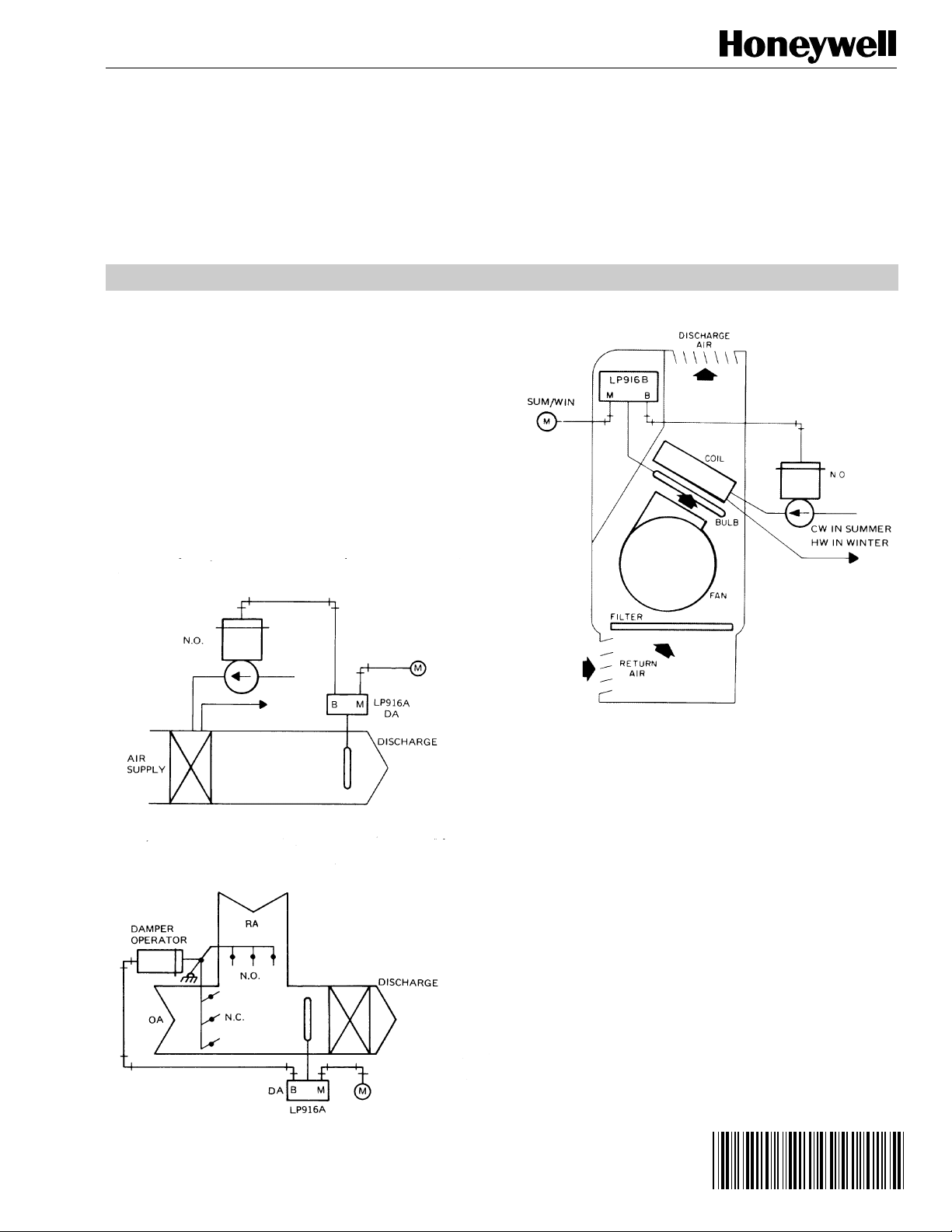
Typical applications for the LP916A are duct-mounted (Fig. 1)
and mixed air control (Fig. 2). The LP916B is typically used
for fan coil unit control (Fig. 3). Typical applications for the
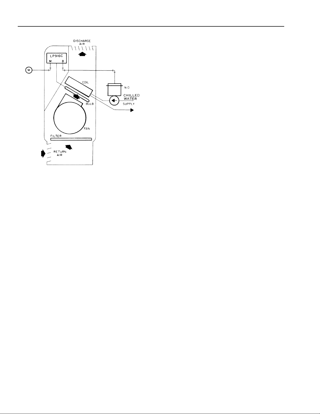
reverse acting LP916C are cooling coil control similar to
Figure 1 or fan coil control (Fig. 4).
LP916A-C Pneumatic
SERVICE DA TA
S5783-1
Fig. 1. Typical LP916A duct-mounted heating application.
S5785-2
Fig. 2. Typical LP916A mixed air application.
S3803-1
Fig. 3. Typical LP916B fan coil application, heating/
cooling with seasonal changeover.
Copyright © 1987 Honeywell Inc. • All Rights Reserved
Page 2
LP916A-C PNEUMATIC REMOTE BULB THERMOSTATS
S22642
Fig. 4. Typical LP916C fan coil application, cooling only.
SPECIFICATIONS
Models:
LP916A: Direct Acting.
LP916B: Reverse acting at 9 or 13 psi (62 or 90 kPa)
supply pressure (Summer), direct acting at 18 psi
(124 kPa) supply pressure (Winter).
LP916C: Reverse Acting.
Maximum Safe Air Pressure:
25 psi (172 kPa).
Maximum Safe Temperature:
Duct-mounted models 190F (88C); all others 135F (57C).
Nominal Main-Line Pressure:
LP916A & C: 18 psi (124 kPa).
LP916B: 18 psi (124 kPa) heating, 9 or 13 psi (62 or
90 kPa) Cooling.
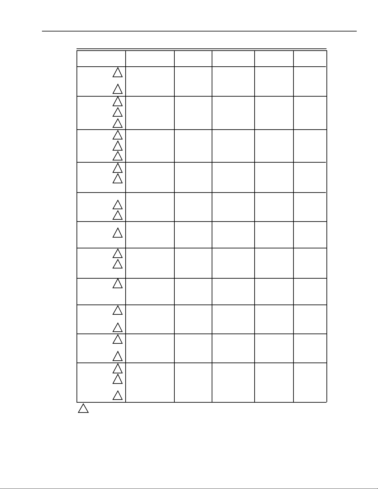
For other LP916 specifications refer to Table 1.
75-5559
2
Page 3
Model
Setpoint
Range F/C
LP916A-C PNEUMATIC REMOTE BULB THERMOSTATS
Table 1. LP916 Specifications.
Throttling
Range F/C
Restrication
Size In.
Bulb Size
Inches
Mounting
Bracket
1LP916A1001 65-85F 3.5F 3/8 x 9 Separate
0.007
LP916A1019 65-85F or 19-30C 3.5F or 2C 0.007 1/2 x 5 Integral
1LP916A1027 65-85F 3.5F 0.007 3/8 x 9 Integral
1 Integral
LP916A1050 17-27C 1.95C 0.007 1/2 x 5 Integral
1
1
1
1
1
LP916A1100
1
1
55-95F 7.0F 0.007 3/8 x 6-11/16LP916A1035
17-27C 1.95C 0.007 3/8 x 9LP916A1068 Integral
13-35C 3.89C 0.007 3/8 x 6-11/16LP916A1076 Integral
17-27C 1.95C 0.007 3/8 x 9LP916A1084 Integral
17-27C 3.80C 0.007 3/8 x 6-11/16LP916A1092 Separate
35-115F 0.007 3/8 x 3-1/214.0F
Integral
55-95F 0.007 3/8 x 77.0FLP916A1118 Integral
65-85F or 19-30C 3.5F or 2CLP916A1126 0.005 3/8 x 9 Separate
3.5F or 2C65-85F or 19-30CLP916A1134 0.005 3/8 x 9 Integral
1
1
55-95F 7.0F 0.005 3/8 x 6-11/16LP916A1142 Integral
17-27C 1.95C 0.005 3/8 x 9LP916A1159 Integral
LP916A1175 0.007 3/8 x 77.0F or 4C40-80F or 4-27C Integral
1
0.007 3/8 x 93.5F65-85FLP916B1009 Separate
3.5F or 2C65-85F or 19-30CLP916B1017 0.007 1/2 x 5 Integral
1
1
65-85F 3.5F 0.007 3/8 x 9LP916B1025 Integral
17-27C 1.95C 0.007 3/8 x 9LP916B1041 Integral
3.5F or 2C65-85F or 19-30CLP916B1058 0.007 1/2 x 5 Integral
1
65-85F 3.5F 0.007 3/8 x 9LP916B1066 Integral
3.5F or 2C65-85F or 19-30CLP916B1074 0.005 3/8 x 9 Separate
3.5F or 2C65-85F or 19-30CLP916B1082 0.005 1/2 x 5 Integral
1
17-27C 1.95C 0.005 3/8 x 9LP916B1090 Integral
3.5F or 2C65-85F or 19-30CLP916B1108 0.005 3/8 x 9 Integral
1
1
65-85F 3.5F 0.007 3/8 x 9LP916C1007 Integral
17-27C 1.95C 0.007 3/8 x 9LP916C1015 Integral
LP916C1023 60-80F or 16-27C 3.5F or 2C 0.007 3/8 x 9 Integral
1
1
1
35-115F 0.007 3/8 x 3-1/214.0FLP916C1072 Integral
55-95F 0.007 3/8 x 77.0FLP916C1080 Integral
3.5F or 2C65-85F or 19-30C 0.007 1/2 x 5LP916C1049 Integral
3.5F or 2C65-85F or 19-30CLP916C1098 0.005 3/8 x 9 Integral
1
40-80F or 4-27C 0.007 3/8 x 77.0F or 4CLP916C1114 Integral
1
Inactive or obsolete.
3
75-5559
Page 4
LP916A-C PNEUMATIC REMOTE BULB THERMOSTATS
OPERATION
LP916A (Direct Acting)
When temperature at the sensing element falls below setpoint
of the LP916A, branchline pressure to the normally open
(n.o.) valve is lowered, and the valve is modulated open to
maintain setpoint temperature.
LP916B (Reverse/Direct Acting)
With main-line pressure at 13 psi (90 kPa) for all except
LP916B1058 which requires 9 psi (62 kPa), the LP916B
operates reverse acting. As the sensed temperature
increases, the branchline pressure decreases and chilled
water flow increases with a n.o. valve.
With a high main-line pressure of 18 psi (124 kPa) or above,
the LP916B operates direct acting. As the sensed
temperature increases, the branchline pressure increases
and hot water flow decreases with a n.o. valve.
LP916C (Reverse Acting)
When the LP916C is used with a normally open valve for
cooling, branchline pressure drops with a rise in sensed air
temperature and the n.o. valve is modulated open to maintain
setpoint temperature.
CLEANING
Remove cover. Use cleaning solvent to clean all surfaces.
Clean the element and capillary tubing, making certain
neither is damaged or kinked. Do not bend the capillary
tubing in a short radius.
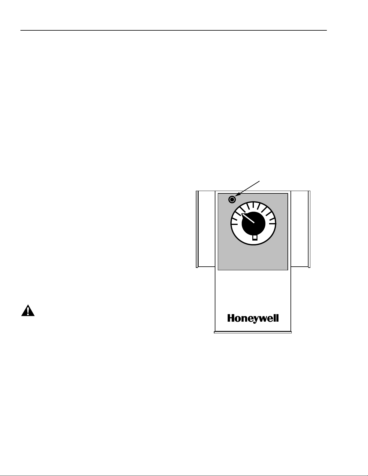
OPERATIONAL CHECK
Use gage adaptor. Insert the gage into the gage tap (Fig. 5)
on the front of the device. Set main-line pressure to 18 psi
(124 kPa), or 13 psi (90 kPa) for LP916B Summer
application. Slowly turn the setpoint knob above and below
bulb ambient temperature. The branchline pressure should
vary from 3 to 13 psi (21 to 90 kPa) pressure, or 13 to 3 psi
(90 to 21 kPa) for reverse acting application within the rated
throttling range. If operation is not satisfactory, recalibrate and
recheck (see CALIBRATION). Turning the knob to above 13
psi (90 kPa) should build branch line to within 2 psi (14 kPa)
of main.
GAGE TAP
NORMAL
COOLER
WARMER
MAINTENANCE
EQUIPMENT REQUIRED
— Commercial Cleaning Solvent or Degreaser.
— Gage Adaptor CCT729A.
— Gage 305965, 0 to 30 psi.
— 5/64-inch Hex wrench.
WARNING
Careless handling of solvents can result in permanent
damage to the respiratory system or skin. Avoid
prolonged inhalation of vapors or contact with skin.
C2861
Fig. 5. LP916 Gage tap location.
75-5559
4
Page 5

CALIBRATION CHECK
Set setpoint knob to temperature measured at bulb location.
Branchline pressure should be 8 ±1 psi (55 ±7 kPa).
CALIBRATION
LP916A & C
LP916A-C PNEUMATIC REMOTE BULB THERMOSTATS
A Apply 18 psi (124 kPa) main-line pressure.
B Measure temperature at sensing bulb location.
C Remove setpoint knob using 5/64-in hex wrench to
loosen setscrew.
D Rotate setpoint shaft to achieve 8 psi (55 kPa)
branchline pressure. Allow enough time for pressure
build-up.
E Replace the knob and position the pointer to
correspond to the temperature sensed by the remote
bulb.
LP916B
A For direct action, follow Steps 1 through 5 for LP916A
and C.
B For reverse action (except LP916B1058), apply 13 psi
(90 kPa) main-line pressure. For the LP916B1058,
apply 9 psi (62 kPa) main-line pressure.
C Adjust switchover lever stop (Fig. 6) to achieve 8 psi
(55 kPa) branchline pressure when the setpoint knob is
set to measured bulb temperature. For the
LP916B1058 model, branchline pressure should be
6 psi (41 kPa).
SWITCHER
LEVER STOP
SWITCHER
SPRING
ADJUSTING NUT
STUD
C8363
Fig. 6. LP916B Automatic switchover mechanism.
5
75-5559
Page 6

LP916A-C PNEUMATIC REMOTE BULB THERMOSTATS
TROUBLESHOOTING
Before troubleshooting the LP916, check branchline piping
and actuators for leaks.
Refer to Figure 7 to troubleshoot the LP916 Thermostat.
BEGIN
MAKE
OPERATIONAL
CHECK
CALIBRATION
YES
CALIBRATION
RECALIBRATE
CHECK PIPING AND
CHECK
OK?
NO
CONTROLLER OK.
ACTUATOR FOR
LEAKS
OPERATES
NO YES
PROPERLY
?
DISCONNECT
BRANCH LINE AT
CONTROLLER
AND PLUG
OUTLET
PRESSURE
BUILDS UP
SMOOTHLY
WHEN SETPOINT
IS CHANGED?
YES
PRESSURE
YES NO
BLEEDS OFF
WHEN SETPOINT
IS MOVED IN
OPPOSITE
DIRECTION?
YES
NO
CHECK MAIN
AIR
PRESSURE
CORRECT
PRESSURE
FOR SEASON
OR
APPLICATION?
NO
TROUBLESHOOT
AIR SUPPLY
REPLACE FILTERS AND
RESTRICTION PLATE
YES
PRESSURE
BUILDS UP
PROPERLY?
NO
REPLACE
CONTROLLER
75-5559
C2860
Fig. 7. LP916 Troubleshooting flowchart.
6
Page 7

REPAIR
LP916A-C PNEUMATIC REMOTE BULB THERMOSTATS
The only repair recommended for the LP916 is the
replacement of the plate and tube assembly, gaskets,
restriction plate, and filters with connector assembly and
gasket. Since February 1984, models have a different
connector assembly with a single gasket, these are included
in Repair Kit 14003113-002, as shown in Figure 8. All
available parts are listed in the PARTS AND ACCESSORIES
section.
EQUIPMENT REQUIRED
Gulmite Head Screw Wrench 316744-00021.
14003113-002 REPAIR KIT INSTALLATION
A Turn off system air and remove LP916 from system.
B Remove and save the three No. 8-32 x 7/16-in. pan
head screws from the connector assembly (Fig. 8) or
plate and tube assembly (Fig. 9 or 10).
C Lift off the connector assembly and gasket or plate and
tube assembly, restriction gasket, restriction plate, body
gasket, and two filters and discard.
D Place new gasket on body and align screw holes.
E Position the new connector assembly on gasket and
align screw holes. A 0.007 in. restriction may be used
for models with a 0.005 in. restriction with no effect on
operation except a slightly higher air consumption. If air
consumption is a problem, connector assembly with a
0.005 in. restriction may be ordered and substituted.
F Insert and tighten the three screws.
G Make operational check (See OPERATIONAL CHECK).
GASKET
CONNECTOR
ASSEMBLY
INDICATES 0.005 IN. RESTRICTION
INDICATES 0.007 IN. RESTRICTION
Fig. 8. Repair kit 14003113-002 (0.007 in. restriction
included in kit).
C8362
NOTE: For 14003113-001 Repair Kit follow directions on
package.
7
75-5559
Page 8

LP916A-C PNEUMATIC REMOTE BULB THERMOSTATS
P ARTS AND ACCESSORIES
PARTS LIST
See Figure 9 for LP916A &C exploded view and Figure 10 for
LP916B exploded view. See Tables 2 and 3 for LP916A &C
parts list and Tables 3 and 4 for LP916B parts list.
Table 2. LP916A and C Parts list (Fig. 9).
Key Part No. Description
Cover
6-32 x 3/16 in. rd-hd slotted screw
6-32 x 1/4 in. pan-hd slotted screw with washer (2)
Spring
Plate
6-32 x 0.31 (5/16) in. rd-hd slotted screw with washer (2)
Base
Baseplate
Scaleplate
8-32 x 5/16 in. slotted pan-hd screw (7)
Palnut
Setpoint Shaft
Knob (includes 8-32 x 5/16 in. hex socket setscrew). Use 5/64 in. key to tighten.
Repair Kit—Consists of Filters, Body Gasket, 0.007 Restriction, and Restriction Gasket
Filters (2)
BodyGasket
0.007 Restriction Plate
Restriction Gasket
Plate and Tube Assembly
8-32 x 7/16 in. pan-hd slotted screw (3)
Connector Assembly (0.007)
Connector Assembly (0.005)
Gasket
Repair Kit—Consists of 14004378-001 Connector Assm. (0.007) & 14004376-001 Gasket
Nozzle
Flapper
Spring
4-40 x 3/16 rd-hd slotted screw
Element and Lever Assembly (see Table 3)
Element and Lever Assembly (see Table 3)
Element and Lever Assembly (see Table 3)
Lever (LP916A)
Lever (LP916C)
Spring
8-32 x 5/16 in. pan-hd slotted screw with star lockwasher
10
11
12
13
14
15
16
17
18
19
20
21
22
23
24
25
26
27
28
29
1
2
3
4
5
6
7
8
9
316294
—
—
—
—
—
—
—
—
—
—
—
—
14003113-001
—
—
—
—
—
—
14004378-001
14004378-002
14004376-001
14003113-002
—
—
—
—
316372A
316372B
316372C
—
—
—
—
75-5559
8
Page 9

LP916A-C PNEUMATIC REMOTE BULB THERMOSTATS
Fig. 9. LP916A and C Exploded view (See Tables 2 and 3).
9
S22649
75-5559
Page 10

LP916A-C PNEUMATIC REMOTE BULB THERMOSTATS
Table 3. LP916A-C Element and lever assemblies.
Assembly
Part No. Part No. Bulb Size in. (mm)
316372A A1001, A1027, A1068, B1009,
316372B A1019, B1017, B1058, C1049 1/2 x 5-3/4
316372Ç A1035, A1076, A1118, A1126,
Key Part No. Description
Cover
Nut
Lever
Element and Lever Assembly (see Table 3)
Element and Lever Assembly (see Table 3)
Element and Lever Assembly (see Table 3)
Stud
Spring
Lever
4-48 x 3/16 in. hex-hd screw
4-48 nut
8-32 x 0.31 (5/16) in. rd-hd slotted screw with washer (2)
Base
Spring
Disc Assembly
Diaphragm
Baseplate
8-32 x 5/16 in. slotted pan-hd screw (7)
Palnut
Setpoint Shaft
Knob (includes 8-32 x 5/16 in. hex socket setscrew). Use 5/64 in. key to tighten.
Repair Kit—Consists of Filters, Body Gasket, 0.007 Restriction, and Restriction Gasket
Filters (2)
BodyGasket
0.007 Restriction Plate
Restriction Gasket
Plate and Tube Assembly.
8-32 x 7/16 in. pan-hd slotted screw
Connector Assembly (0.007)
Connector Assembly (0.005)
Gasket
Repair Kit—Consists of 14004378-001 Connector Assm. (0.007) & 14004376-001 Gasket
Nozzle
Flapper
Spring
4-40 x 3/16 in. rd-hd slotted screw (3).
6-32 x 3/16 in. rd-hd slotted screw
Spring
8-32 x 5/16 in. pan-hd slotted screw with star lockwasher (2)
10
11
12
13
14
15|
16
17
18
19
20
21
22
23
24
25
26
27
28
29
30
31
32
33
34
1
2
3
4
5
6
7
8
9
316294
—
—
316372A
316372B
316372C
—
—
—
—
—
—
—
—
—
—
—
—
—
—
316732
14003113-001
—
—
—
—
—
—
14004378-001
14004378-002
14004376-001
14003113-002
—
—
—
—
—
—
—
B1025, B1041, B1066, C1007,
C1023
A1134, A1142, A1159, A1175,
B1074, B1082, B1090, B1108,
C1080, C1098, C1114
Table 4. LP916B Parts list (Fig. 10).
3/8 x 9-1/2
(9.5 x 241)
(13 x 146)
3/8 x 6-3/4
(10 x 172)
75-5559
10
Page 11

LP916A-C PNEUMATIC REMOTE BULB THERMOSTATS
Fig. 10. LP916B Exploded view.
11
S22649
75-5559
Page 12

LP916A-C PNEUMATIC REMOTE BULB THERMOSTATS
ACCESSORIES
A Gage 305965 (0 to 30 psi).
B Gage Adaptor MQP729.
C Internal Mounting Bracket AK3993.
D Mounting Kits for fan coil units:
316016A with small bracket.
316016B with full length bracket.
316016C with scaleplate, knob, and mounting
screws only.
By using this Honeywell literature, you agree that Honeywell will have no liability for any damages arising out of your
use or modification to, the literature. You will defend and indemnify Honeywell, its affiliates and subsidiaries, from and
against any liability, cost, or damages, including attorneys’ fees, arising out of, or resulting from, any modification to the
literature by you.
Home and Building Control
Honeywell Inc.
Honeywell Plaza
P.O. Box 524
Minneapolis MN 55408-0524
75-5559 Rev. 6-87 Printed in U.S.A.
75-5559
Home and Building Control
Honeywell Limited-Honeywell Limitée
155 Gordon Baker Road
North York, Ontario
M2H 2C9
12
Helping You Control Your World
 Loading...