

Page 1
LP907A
g
(
y
y
g
g
g
g
g
g
ge(s)
(
g (
(
g
[
j
y
g
g
g
g
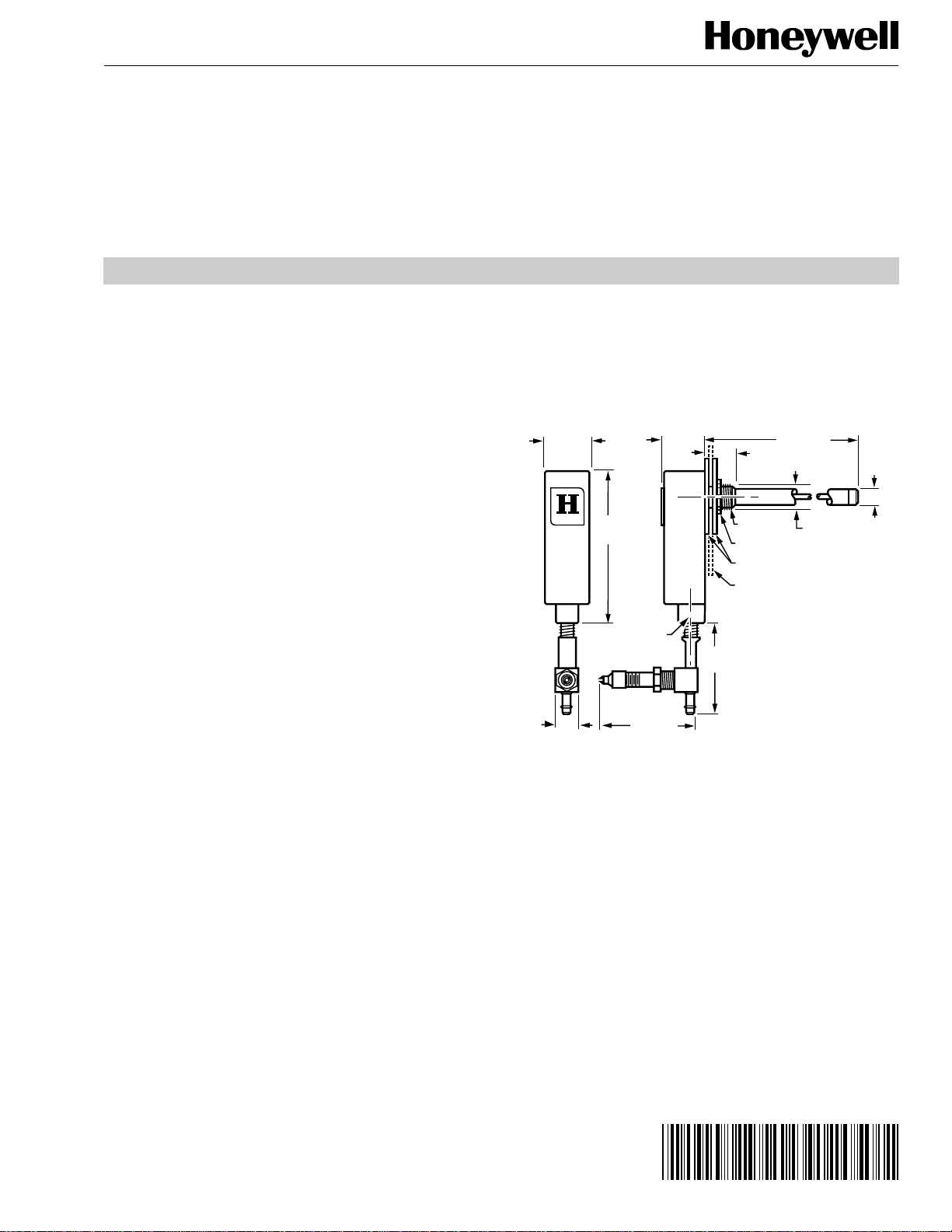
1-1/16 (27)
7/8 (22)
5/8
(16)
3/8 NPT
NUT
SPACERS (2)
DUCT WALL
18-3/4 (476)
3-7/16
(87)
1/8 NPT
2
(51)
2-1/4 (57)
1/2
(13)
HONEYWELL
11/32
(9)
3/4 DIAM. HOLE
(MINIMUM)
REQUIRED
FOR MOUNTING
M7996A
)
g
yrig
95- 1612EF
Airstream Insertion Thermostat
INSTALLATION INSTRUCTIONS
APPLICATION
The LP907 Airstream Insertion Thermostat is a direct-acting,
le-pipe, bleed-type controller with a rigid element. The
sin
LP907B
with lockout capabilit
for lockout durin
replacin
Switchin
no longer available) was the same as the LP907A
. It included a pneumatic switching rela
summer (cooling) operation. When
the LP907B, use an LP907A and an RP670A
Relay.
SPECIFICATIONS
Model:
Dimensions:
Temperature Ratings:
Operatin
Storage (Maximum Safe): 150°F (66°C).
Throttlin
Setpoint Ran
Setpoint Adjustment:
Element:
Direct-acting, bleed-type controller.
See Fi
. 1.
Range: 40°F to 140°F (4°C to 60°C).
Range (adjustable internally): 10 to 70°F (6 to 39K).
: 40°F to 140°F (4°C to 60°C);
Dial Front: 40°F to 90°F (4°C to 32°C),
Dial Back: 90°F to 140°F
32°C to 60°C).
Dial under cover.
18-3/4 in. (476 mm) long x 3/8 in. (10 mm) diameter
invar rod and seamless brass tube.
When mountin
with an immersion well, use 107408 Heat
Conductive Compound in the well to improve response.
NOTE: For further information concernin
wells, see Form
68-0040 Immersion Wells and Compression Fittin
for Temperature Controllers.
Fig. 1. Dimensions of LP907A in in. (mm).
s
Maximum Safe Air Pressure:
Air Connections:
Mounting:
Push-on barb for 1/4 in.
Insertion with locknut on insertion couplin
20 psi
138 kPa).
6 mm) poly tubing.
Accessories:
14002913-002 External Restriction
301572A00767 Calibration Ad
309387 Filter Assembl
CCT2085 Gage Adapter.
BEFORE INSTALLING
Use with a 0.007-inch (0.17 mm) diameter restriction such as
the 14002913-002 Filter/Restriction Cartrid
restriction in the MP516B and C Damper Operators.
® U.S. Registered Trademark
Cop
ht © 2001 Honeywell • All Rights Reserved
.
0.007 in. (0.2 mm)].
ustment Key.
e or the integral
INSTALLATION
.
The LP907A can be mounted in any position. See Fig. 2
through 4 for mounting configurations.
OPERATION
Due to its bleed-type construction and wide throttling range,
the LP907A provides submaster-type operation (most often
low-limit control
h 7 for typical hookups.
throu
in a normal unit ventilator system. See Fig. 5
Page 2
LP907A AIRSTREAM INSERTION THERMOSTAT
g
(
y
g
g
g
y
g
(
g
)
g (
g
(
j
y (
y
y
g
g
gly
j
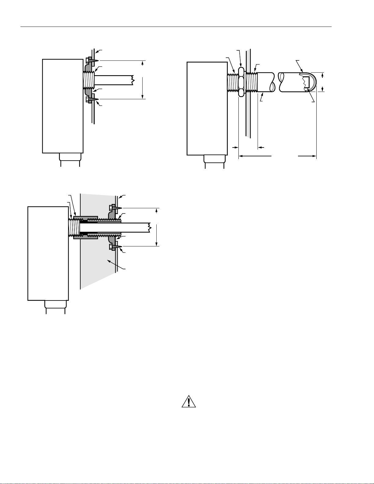
DUCT
LP907
3/8 NPT
3/8
WASTE NUT
SHEET METAL
MTG. SCREWS (2)
M17676
1-11/16
(43)
Fig. 2. Mounting on standard sheet metal duct.
3/8 NPT COUPLING
3/8 NPT
LP907
DUCT
3/8 CLOSE
NIPPLE
3/8
WASTE NUT
SHEET METAL
MTG. SCREWS (2)
INSULATION
1-11/16
(43)
HEX COLLAR
LP907
3/8 NPT
1-3/16 (29)
1/2 NPT
IMMERSION
WELL
19-1/16 (484)
CONDUCTIVE
COMPOUND
ELEMENT
Fig. 4. Mounting in boiler wall with immersion well.
MAINTENANCE
IMPORTANT
• Mechanical devices require periodic service to
provide continued satisfactory performance. Controls
are no exception.
• How accurate and how trouble free your control
system remains in years to come depends largely on
the maintenance given to it.
• For best results, service all devices in your system at
one time.
• Time and trouble can be saved by arranging with
Honeywell for a maintenance agreement which will
guarantee expert, economical care, and insure
maximum life and efficiency from your system.
M17678
1/2
(13)
M17679
Fig. 3. Mounting on insulated duct.
When discharge air temperatures are within the throttlin
range, the LP907A control point is reset based upon room
thermostat branch-line pressure
the LP907A to directl
control airstream temperature except
BLP) changes. This allows
during morning warm-up and heavy-load conditions.
NOTE: Usin
a damper operator other than an MP516B
requires a 0.007 in. restriction upstream. The
restriction allows the LP907A to bleed fast enou
h to
control BLP.
. 6, the RP670 switching relay is connected directly to
In Fi
the main. The rela
action
locks out
the LP907A during the
summer (cooling) cycle when main pressure is 14 psi
97 kPa) or less. (Normal pressure ranges from 13 to 18 psi
[90 to 124 kPa]
95-1612EF 2
. This allows 1 psi
7 kPa) main line variation.
Equipment Required
•
3/16-in. open end wrench.
• Commercial cleanin
• Lubricant
part no. 310879).
• Calibration Ad
solvent.
ustment Ke
part no. 301572A00767).
Inspection, Cleaning and Lu bri cati on
1.
Visuall
2.
Remove dirt and corrosion from the element and bod
3.
Check air lines for dama
4.
Remove the cover and inspect internal parts.
5.
Remove dirt and corrosion with soft brush or commercial cleanin
inspect the device exterior.
e and leaks.
solvent.
CAUTION
Equipment Damage Hazard.
Can damage the device beyond repair.
Use lubricant sparin
nozzle (see Fig. 8).
6.
Lubricate pivot points and ad
and keep it away from the air
ustment threads.
.
Page 3
LP907A AIRSTREAM INSERTION THERMOSTAT
M
M5450
LP907A
VP514
14002913-002
0.007 IN. RESTRICTION
(NOT FURNISHED)
)
j
g
g
y
g
g
q
g
g
y
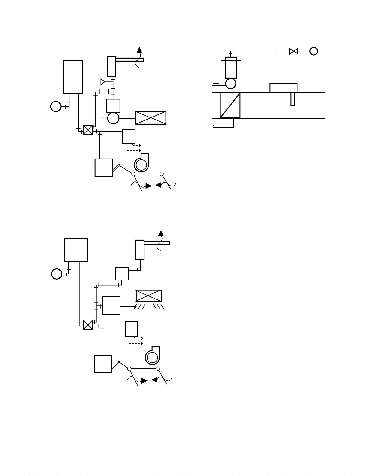
ROOM
THERMOSTAT
M
M
LP907A
B
VP512A
VALVE
H L
MP516A
OPERATOR
Fig. 5. Typical operation.
D.A.
H
RP418 E-P
RELAY
WIRE IN PARALLEL
WITH FAN MOTOR
FAN
R.A.
C
Fig. 7. Typical operation of duct mounted LP907A.
Operational Check
LP907A
1.
Ensure BLP ahead of the restriction (or MP516B
equals mainline pressure. If it does not:
ust the room thermostat in order to obtain equal
O.A.
M5419B
a. Ad
pressure.
b. Decrease the air temperature at the device sensin
element or increase the setpoint.
RESULT:BLP to the valve should decrease, and
vice versa.
Return setpoint to the ori
c.
inal setting.
TP972
M
B
M
WINTER
18 psi (1.24 BAR)
SUMMER
13 psi (.90 BAR)
MP516A
Fig. 6. Typical operation of LP907A in heating-cooling
application (unit ventilator).
RP670
MP516A
LP907A
FACE AND BY-PASS
RP418 E-P
RELAY
H L
WIRE IN PARALLEL
WITH FAN MOTOR
R.A.
D.A.
FAN
O.A.
M5448B
LP907B, or LP907A with RP670A Switching Relay
1.
Supply 13 psi (90 kPa) main air pressure to the LP907B
, or 18 psi (124 kPa) main air pressure to the
rela
RP670A, to simulate summer operation.
2.
Block BLP to the LP907 to ensure temperature chan
at the sensin
element do not affect room thermostat
control of system operation.
3.
BLP to the valve should settle to e
NOTE: The restriction can cause a sli
pressure settlin
4.
5.
18 psi (124 kPa) main air pressure to the relay.
Suppl
Perform the LP907A operational check.
.
ual thermostat BLP.
ht delay in
Calibration Check
When BLP equals 8 ± 1 psi (55 ± 7 kPa) with the air
temperature at setpoint, the controller is properly calibrated.
es
3 95-1612EF
Page 4

LP907A AIRSTREAM INSERTION THERMOSTAT
y
(
(
(
)
(
(
g
g
g
)
y
y
g
(
j
j
g
j
g
gag
g
g
Printed in U.S.A. on recycled
paper containing at least 10%
post-consumer paper fibers.
Adjustments
Refer to Fig. 8 and the Maintenance section.
Throttling Range
4.
ust the setpoint dial until the setpoint indicator
Ad
matches the current temperature at the sensin
5.
Tighten the setpoint-dial locking screw.
6.
ust the calibration screw until BLP is 8 psi (55 kPa).
Ad
7.
Turn the setpoint dial to the desired setpoint.
element.
IMPORTANT
— Always check calibration after adjusting the throttling
range.
— Set the throttling range as near to the minimum value
that the system permits without causing short cycling.
NOTE: For unit ventilator use, the throttling range is factor
set at 25°F
14K) and requires no further adjustment.
TO CHECK THE ACTUAL THROTTLING RANGE:
1.
Turn the setpoint dial until branch line pressure
BLP) is
less than 1 psi (7 kPa).
2.
Turn dial counterclockwise until BLP is 3 psi
21 kPa
and note setpoint.
3.
Continue to turn the dial until BLP is 13 psi
4.
The difference between the setpoints at 3 and 13 psi
90 kPa).
21 and 90 kPa) BLP is the throttling range.
TO ADJUST THE THROTTLING RANGE:
1.
Loosen the throttlin
range indicator locking screw with
the thermostat key. See Fig. 8.
NOTE: If there is no lockin
screw, simply squeeze the
throttling range adjustment clip to release it.
2.
Slide the indicator until its leadin
edge is on the
desired setting.
IMPORTANT
When replacing the cover, be careful not to disturb
the throttling range adjustment clip.
Calibration
NOTE: Calibration procedures are the same for all models
with the exception that the LP907B (or LP907A used
with an RP670
main air pressure suppl
1.
Loosen the setpoint-dial lockin
2.
With 3/16 in.
ad
ustment screw until the primary lever is parallel with
the base.
3.
Turn the calibration screw until the nozzle lever is
parallel with the base.
cannot be calibrated unless the rela
is 18 psi (124 kPa).
screw.
5 mm) open-end wrench, turn the setpoint
IMPORTANT
When replacing the cover, be careful not to disturb
the throttling range adjustment clip.
PRIMARY
LEVER
THROTTLING RANGE
INDICATOR LOCKING
SCREW
INSET "A"
SETPOINT
ADJUSTMENT
SCREW
GAGE
ADAPTER
TANK
VALV E
GAGE
TEE
CALIBRATION
SCREW
THROTTLING
RANGE
ADJUSTMENT
CLIP
NOZZLE
LEVER
BASE
Fig. 8. LP907A Adjustments.
TROUBLESHOOTING
1.
If the LP907 does not operate smoothly when makin
an operational check, replace the filter (located between
the
2.
If results do not improve, check the pneumatic line
restriction to determine whether there is proper airflow.
3.
If the pneumatic line has evidence of oil, pur
with refri
IMPORTANT
e tee and device base).
erant and eliminate the source of oil.
Keep oil out of the pneumatic line to avoid recurring
problems.
SETPOINT
INDICATOR
SETPOINT
DIAL
LOCKING
SCREW
SETPOINT
DIAL
M17677BB
e the line
Home and Building Control Home and Building Control
Honeywell Honeywell Limited-Honeywell Limitée
1985 Douglas Drive North 35 Dynamic Drive
Golden Valley, MN 55422 Scarborough, Ontario
95-1612EF B.B. 4-01
M1V 4Z9
www.honeywell.com
Page 5

LP907A
g
q
g
g
)
g
(
ge (
(
glag
(
(
)
g
(
(
y
(
g
q
g
q
g
g
g
g
g
27 (1-1/16)
22 (7/8)
16
(5/8)
3/8 NPT
ÉCROU
ENTRETOISES (2)
PAROI DE LA GAINE
476 (18-3/4)
87
(3-7/16)
1/8 NPT
51
(2)
57 (2-1/4)
13
(1/2)
HONEYWELL
9
(11/32)
OUVERTURE DE
3/4 PO (MINIMUM
REQUIS POUR
L'INSTALLATION)
MF7996A
yrig
95- 1612EF
Thermostat de gaine
NOTICE D’INSTALLATION
APPLICATION
Le thermostat de gaine LP907 est un régulateur de purge à
action directe et à une canalisation comportant un élément
sensible ri
mêmes caractéristi
verrouilla
servant au verrouilla
refroidissement
ide. Le LP907B (qui n’est plus offert) avait les
ues en plus d’offrir une fonction de
e. Il comprenait également un relais de commutation
e pendant les mois d’été (en mode de
. Lors du remplacement du LP907B, utiliser un
LP907A et un relais de commutation RP670A.
CARACTÉRISTIQUES TECHNIQUES
Modèle :
Encombrement :
Températures nominales :
Gamme de service : 4 à 60 °C
Température d’entreposa
Bande proportionnelle : réglage de façon interne de 6 à 39 K
Gamme de ré
Réglage du point de consigne :
régulateur de purge à action directe.
voir la Fi
. 1.
40 à 140 °F).
max. admissible) : 66 °C (150 °F).
10 à 70 °F).
e du point de consigne : 4 à 60 °C
40 à 140 °F).
Devant du cadran : 4 à 32 °C
40 à 90 °F
Arrière du cadran : 32 à 60 °C (90 à 140 °F ).
cadran sous le couvercle.
AVANT D’INSTALLER CE PRODUIT…
Utiliser avec un réducteur de 0,17 mm (0,007 po) de diamètre
ue le filtre/cartouche de restriction 14002913-002 ou le
tel
réducteur inté
ue le thermostat de gaine est employé avec une gaine
Lors
ré aux actionneurs de registre MP516B ou C.
d’immersion, utiliser du composé thermoconducteur 107408
dans la
REMARQUE : Pour obtenir des rensei
aine pour que l’élément réagisse mieux.
nements plus détaillés
sur les
aines, consulter la publication 68-0040
sur les gaines d’immersion et raccords à
compression pour ré
ulateurs de température.
INSTALLATION
Le LP907A peut être installé dans n’importe quelle position.
Voir les Fi
d’installation.
. 2 à 4 pour observer différentes méthodes
Type d’élément sensible :
e en invar de 10 mm (3/8 po) de diamètre et de 476 mm
ti
18-3/4 po) de longueur et tube de laiton sans joint.
Pression d’air maximale admissible :
Raccords d’air :
mère de 6 mm (1/4 po).
pol
Installation :
Accessoires :
raccord cannelé à pression pour tube de
par insertion, avec écrou du côté du raccord.
14002913-002 Restriction externe de 0,2 mm
301572A00767 Clé d’étalonna
309387 Filtre.
CCT 2085 Adaptateur pour manomètre.
® Mar que de commerce déposée aux É.-U.
ht © 2001 Honeywell Tous droits réservés
Cop
e.
138 kPa
20 psig).
0,007 po).
Fig. 1. Encombrement en mm (po) du LP907A.
Page 6

LP907A THERMOSTAT DE GAINE
g
(
g
y
(
q
q
g
g
(cy
)
(
(
yag
(
q
g
yag
g
(
j
GAINE
LP907
MF17676
3/8 NPT
ÉCROU DE VIDANGE
3/8
VIS
AUTOTARAUDEUSES (2)
43
(1-11/16)
Fig. 2. Installation sur une gaine d’air en tôle standard.
RACCORD 3/8 NPT
3/8 NPT
LP907
GAINE
RACCORD
ÉTROIT 3/8
ÉCROU DE
VIDANGE 3/8
VIS
AUTOTARAUDEUSES (2)
ISOLANT
43
(1-11/16)
MF17679
Fig. 3. Installation sur une gaine isolée.
FONCTIONNEMENT
Parce qu’il s’agit d’un thermostat de purge et qu’il offre une
bande proportionnelle lar
du thermostat
et fonctionner dans la plupart des cas à la
manière d’un régulateur à minimum) dans un système de
ventilation ordinaire. Les Fi
raccordement t
pe.
Lorsque la température de l’air de soufflage se situe dans les
limites de la bande proportionnelle du LP907A, les variations
de la pression de la canalisation secondaire provenant du
thermostat d’ambiance déclenchent le fonctionnement du
LP907A
point de contrôle). Ce faisant, le LP907A commande
directement la température de l’écoulement d’air, sauf lors de
la reprise matinale et
REMARQUE : Lors
MP516B est utilisé, il faut ajouter un réducteur
de 0,007 po en amont. Le réducteur permet au
LP907A de pur
rapidité pour commander la pression de la
canalisation secondaire.
e, le LP907A peut prendre la relève
. 5 à 7 illustrent des schémas de
uand la charge est trop importante.
u’un actionneur de registre autre que le
er l’air avec suffisamment de
MANCHON
MF17678
LP907
HEXAGONAL
3/8 NPT
1/2 NPT
29 (1-3/16)
COMPOSÉ
THERMOCONDUCTEUR
GAINE
D’IMMERSION
484 (19-1/16)
ÉLÉMENT
SENSIBLE
Fig. 4. Installation sur la paroi d’une chaudière
avec gaine d’immersion.
MAINTENANCE
IMPORTANT
• Les appareils mécaniques doivent faire l’objet d’un
entretien périodique si l’on veut qu’ils fonctionnent de
façon satisfaisante sans interruption. Les régulateurs
ne font pas l’exception.
• La précision du système de régulation et son bon
fonctionnement dépendent largement des soins
qu’on y apporte.
• Pour de meilleurs résultats, mieux vaut faire l’entretien
de tous les appareils du système en même temps.
• On peut gagner du temps et s’éviter des problèmes
en confiant la maintenance à Honeywell et s’assurer
ainsi d’obtenir des soins experts, garantis et
économiques qui permettront de tirer du système le
meilleur parti et la plus grande efficacité possibles.
Matériel requis
• Clé à fourche de 3/16 po.
Solvant de netto
•
• Lubrifiant
pièce no 310879).
• Clé d’étalonnage (pièce no 310572A00767).
Inspection, nettoyage et lubrification
1.
Inspecter
2.
Enlever la saleté et la corrosion de l’élément et du corps.
3.
Vérifier les raccords d’air pour s’assurer
domma
4.
Retirer le couvercle et inspecter les pièces internes.
5.
Enlever la saleté et la corrosion à l’aide d’une brosse
douce ou d’un solvant de netto
e ni fuite.
e commercial.
de visu
l’extérieur de l’appareil.
u’il n’y a ni
e commercial.
13
(1/2)
. 6, le relais de commutation RP670 est directement
Dans la
Fi
relié à la canalisation principale. L’action de ce relais met le
LP907A hors service pendant les mois d’été
refroidissement
, lorsque la pression de la canalisation
cle de
principale est de 97 kPa (14 psig) ou moins [pression normale
90 à 124 kPa
variation de 7 kPa
95-1612EF 2
13 à 18 psig)]. On peut ainsi obtenir une
1 psig) dans la canalisation principale.
MISE EN GARDE
Risque d’endommager le matériel.
Risque de dommage irréparable.
Utiliser très peu de lubrifiant et le tenir éloi
buses d’air
6.
Lubrifier les points d’articulation et les filets d’a
voir la Fig. 8).
né des
ustement.
Page 7

THERMOSTAT
g
MF5448B
AIR REPRIS
AIR FRAIS
MP516A
LP907A
AIR DE
SOUFFLAGE
M
B
M
VENTILATEUR
TP972
RP670
EN HIVER
1,24 BAR (18 psi)
ÉTÉ
0,90 BAR (13 psi)
REGISTRE FRONTAL
ET DE DÉRIVATION
MP516A
H L
RELAIS
É/P RP418
RACCORDER EN
PARRALÈLE AVEC LE
MOTEUR DU VENTILATEUR
(
j
g
g
É
g
q
(
)
(
q
q
y
g
g
q
(
D'AMBIANCE
M
B
LP907A
AIR DE
SOUFFLAGE
LP907A THERMOSTAT DE GAINE
5.
Vérifier le fonctionnement du LP907A.
Vérification de l’étalonnage
Lorsque la pression de la canalisation secondaire est de 55
±7 kPa (8 ± 1 psi) et que la température de l’air est égale au
point de consi
ne, le régulateur est correctement étalonné.
M
MF5419B
OPÉRATEUR
MP516A
VANNE
VP512A
H L
AIR REPRIS
H
RELAIS
É/P RP418
RACCORDER EN
PARRALÈLE AVEC LE
MOTEUR DU VENTILATEUR
VENTILATEUR
Fig. 5. Fonctionnement type.
Vérification du fonctionnement
LP907A
1.
S’assurer que la pression de la canalisation secondaire
en amont du réducteur
pression de la canalisation principale. Si ce n’est pas le
cas :
uster le thermostat d’ambiance pour obtenir une
a. A
pression é
ale.
b. Réduire la température de l’air à l’élément sensible
de l’appareil ou au
SULTAT :La pression de la canalisation
R
Ramener le point de consi
c.
LP907B ou LP907A avec relais de commutation
RP670A
1.
Appli
90 kPa
au RP670A pour simuler le fonctionnement en mode de
refroidissement
2.
3.
4.
uer la pression de la canalisation secondaire au
Blo
LP907 pour veiller à ce
à l’élément sensible n’influence pas la commande du
stème par l’entremise du thermostat d’ambiance.
s
La pression de la canalisation secondaire à la vanne
devrait se stabiliser et é
canalisation secondaire au thermostat.
REMARQUE : Le réducteur pourrait retarder
Appli
principale de 124 kPa
uer une pression de la canalisation principale de
13 psi) au relais LP907B ou de 124 kPa (18 psi
lé
uer une pression de pression de la canalisation
pression.
ou du MP516B) est égale à la
menter le point de consigne.
secondaire à la vanne devrait diminuer
et vice versa.
ne à sa valeur d’origine.
été).
ue la variation de la température
aler la pression de la
èrement la stabilisation de la
18 psi) au relais.
C
AIR FRAIS
Fig. 6. Fonctionnement type d’un LP907A au sein d’un
système de chauffage-refroidissement
(ventilateur autonome).
M
14002913-002
RÉDUCTEUR
VP514
DE 0,2 mm (0,007 PO)
(NON FOURNIE)
LP907A
MF5450A
Fig. 7. Fonctionnement type d’un LP907A monté en gaine.
Ajustements
Voir la Fig. 8 et la section sur la Maintenance.
Bande proportionnelle
IMPORTANT
— Il faut toujours vérifier l’étalonnage après avoir ajusté
la bande proportionnelle.
— Régler la bande proportionnelle le plus près possible
de la valeur minimale acceptée par le système sans
provoquer des cycles de fonctionnement trop courts.
3 95-1612EF
Page 8

LP907A THERMOSTAT DE GAINE
g
j
glag
jusq
jusq
q
g
jusq
(
g
g
y
g
) q
q
(
g
À
j
q
ge jusq
j
jusq
g
g
g
glag
(
y
q
q
q
g
REMARQUE : Lorsque le régulateur est destiné à un
ventilateur autonome, la bande proportionnelle
lée en usine à 14 K (25 ° F) et n’a pas
est ré
besoin d’être a
ustée.
POUR VÉRIFIER LA BANDE PROPORTIONNELLE ACTUELLE :
1.
Faire tourner le cadran de ré
e du point de consigne
u’à ce que la pression de la canalisation secondaire
soit inférieure à 7 kPa (1 psi).
2.
Faire tourner le cadran dans le sens antihoraire
ue la pression de la canalisation secondaire
ce
atteigne 21 kPa (3 psi) et prendre note du point de
3.
Continuer de tourner le cadran
u’à ce que la
ne.
consi
pression de la canalisation secondaire atteigne 90 kPa
13 psi).
4.
La différence entre les points de consi
ne à 21 et à
90 kPa (à 3 et à 13 psi) de pression dans la canalisation
secondaire correspond à la bande proportionnelle.
POUR AJUSTER LA BANDE PROPORTIONNELLE :
1.
Desserrer la vis de blocage de l’indicateur de la bande
proportionnelle à l’aide de la clé à thermostat. Voir la
. 8.
Fi
REMARQUE : S’il n’
a pas de vis de blocage, il suffit
de serrer la pince de réglage de la bande
proportionnelle puis de la relâcher.
2.
lisser l’indicateur jusqu’à ce que son rebord
Faire
avant soit à la position désirée.
IMPORTANT
Prendre soin de ne pas bouger la pince de réglage de
la bande proportionnelle en refermant le couvercle.
u’à
5.
Resserrer la vis de bloca
point de consi
6.
Ajuster la vis d’étalonnage jusqu’à ce que la pression de
ne.
la canalisation secondaire attei
7.
Faire tourner le cadran de ré
e du cadran de réglage du
ne 55 kPa (8 psi).
e du point de consigne
à la valeur désirée.
IMPORTANT
Prendre soin de ne pas bouger la pince de réglage de
la bande proportionnelle en refermant le couvercle.
CADRAN DE RÉGLAGE
DU POINT DE CONSIGNE
VIS DE BLOCAGE
DU CADRAN DE
RÉGLAGE DU POINT
DE CONSIGNE
INDICATEUR
DU POINT DE
CONSIGNE
VIS D’AJUSTEMENT
ADAPTATEUR
DE
MANOMÈTRE
VANNE DU
RÉSERVOIR
MF17677
VIS DE BLOCAGE DE
L’INDICATEUR DE LA
BANDE PROP.
EN
MÉDAILLON
VIS D’ÉTALONNAGE
PINCE D’AJUSTEMENT
DE LA BANDE
PROPORTIONNELLE
PRISE DE
MANOMÈTRE
DÉTENTE
BASE
LEVIER
PRINCIPAL
DU POINT DE CONSIGNE
Fig. 8. Ajustement du LP907A.
Étalonnage
DÉPANNAGE
REMARQUE : La méthode d’étalonnage est la même pour
tous les modèles à l’exception du LP907B (ou
du LP907A utilisé avec un RP670
être ré-étalonné à moins
ue la pression
ui ne peut
fournie par la canalisation principale soit de
124 kPa
1.
Desserrer la vis de bloca
18 psi).
e du cadran de réglage du
point de consigne.
2.
l’aide d’une clé à fourche de 5 mm (3/16 po), faire
tourner la vis d’a
ce
3.
ue le levier principal soit parallèle à la base.
Faire tourner la vis d’étalonna
ustement du point de consigne jusqu’à
u’à ce que la
détente soit parallèle à la base.
4.
uster le cadran de réglage du point de consigne
A
u’à ce que l’indicateur du point de consigne
corresponde à la température actuelle à l’élément
sensible.
By using this Honeywell literature, you agree that Honeywell will have no liability for any damages arising out of your use
or modification to, the literature. You will defend and indemnify Honeywell, its affiliates and subsidiaries, from and against
any liability, cost, or damages, including attorneys’ fees, arising out of, or resulting from, any modification to the literature
by you.
Régulation résidentielle Régulation résidentielle et commerciale
et commerciale
Honeywell 35, Dynamic Drive
1985 Douglas Drive North Scarborough (Ontario)
Golden Valley, MN 55422 M1V 4Z9
Honeywell Limited-Honeywell Limitée
1.
Si le LP907 ne fonctionne pas correctement à la
vérification, remplacer le filtre
situé entre la prise de
manomètre et la base de l’appareil.
2.
3.
a pas d’amélioration, vérifier le réducteur de la
S’il n’
canalisation pneumati
est adé
uat.
ue pour établir si le débit d’air
S’il semble y avoir de l’huile dans la canalisation
pneumati
fri
ue, vidanger la canalisation avec du
origène et éliminer la source d’huile.
IMPORTANT
Pour éviter que le problème ne se répète, éviter que
de l’huile ne pénètre dans la canalisation
pneumatique.
95-1612EF B.B. 4-01
Imprimé aux États-Unis sur du papier
recyclé contenant au moins 10 %
de fibres post-consommation.
www.honeywell.com
 Loading...