

Page 1
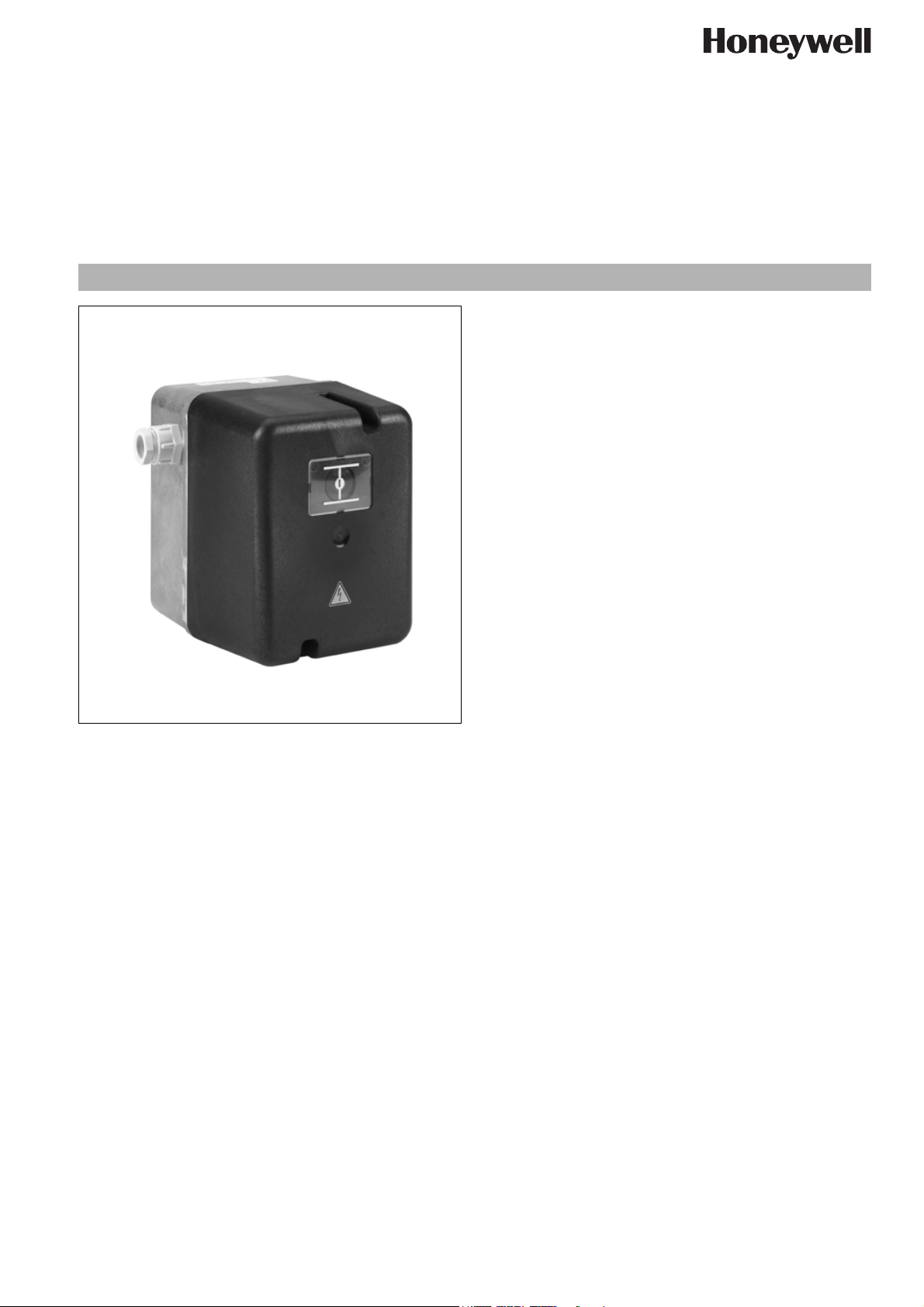
LKS 310
Actuator for air dampers on multi-stage
and modulating burners
Instruction Handbook
CONTENTS
Application ........................................................................... 1
Description ........................................................................... 2
Features ................................................................................ 2
Specification ........................................................................ 2
Type overview ..................................................................... 2
Technical data ..................................................................... 3
Ordering information ............................................................3
Standards and approvals .................................................... 3
Accessories ........................................................................ 3
Dimensional drawing ........................................................... 4
Shaft versions ..................................................................... 4
Circuit diagrams .................................................................. 5
Installation ............................................................................7
Safety Guidelines ................................................................7
Commissioning and Inspection .......................................... 7
Safety Guidelines ................................................................7
Function control .................................................................. 7
Repairing and Disposal ....................................................... 7
APPLICATION
The LKS 310 air damper actuator is designed to be fitted to
multi-stage or modulating oil and gas burners with fully
closed position.
EN1C-0114SZ20 R0506
www.honeywell.com 1
Page 2

LKS 310 Actuator for air dampers on multi-stage and modulating burners
honeyvell.energy
DESCRIPTION
A synchronous motor powers an output shaft and a backlashfree
cam shaft via a gear reducer.
The cam shaft operates limit and auxiliary switches. The position
at which one of the limit or auxiliary switches operates can be adjusted steplessly within the operating range using the associated
cam disc. Manually adjustable lever-operated cams or spindledriven cams, which can be adjusted with a screwdriver, are available.
FEATURES
Electric actuator up to 15 Nm
• Drive times: 3.5 ... 30 sec.
• Gearing can be decoupled
• Position indicator
• Easily adjustable limit and auxiliary switches
• Synchronous motor
• Particulary stable design in aluminium housing
Variants:
• clockwise or counter clockwise rotation
• with integrated electronic circuitry
• different shaft versions
SPECIFICATION
Type overview
Clockwise rotation
Diagram 2)Shaft 3)Drive
Nr. Nr. s Nm Nm V
S1 5D 30 15 10 230 LKS 310-15 (A-5D-30 S1) Spindle-driven cam
S12 5D 30 15 10 230 LKS 310-21 (A-5D-30 S12) Spindle-driven cam
S7 5B 30 15 10 230 LKS 310-22 (A-5B-30 S7)
S7 5B 10 10 10 230 LKS 310-24 (A-5B-10 S7.1)
S7 5B 15 15 10 230 LKS 310-25 (A-5B-15 S7.1)
S12 5D 7 7 7 110 LKS 310-34 (A-5D-7 S12.1) Spindle-driven cam
S7 5C 30 15 10 230 LKS 310-35 (A-5C-30 S7) IP54
Counter-clockwise rotation
Diagram 2)Shaft 3)Drive
Nr. Nr. s Nm Nm V
S8 5A 3,5 3,5 3,5 230 LKS 310-10 (B-5A-3.5 S8)
S7 5C 3,5 3,5 3,5 230 LKS 310-17 (B-5C-3.5 S7.1)
S7 5B 15 15 10 230 LKS 310-31 (B-5B-15 S7.1)
S7 5B 10 10 10 230 LKS 310-32 (B-5B-10 S7.1)
Legende
1) when viewing from direction A (see dimensional drawing)
2) see “Circuit diagrams”
3) see “Shaft versions”
4) at 50 Hz for 90°
at 60 Hz, Drive times are about 20 % shorter
5) under nominal conditions
under extreme conditions (e.g. +60 °C, 230V -15%) the torques will be 25% lower
6) +10% -15%; 50...60Hz
at -15%; torque reduced by approx. 20% at undervoltage
7) Standard: Lever-operated cam
1)
time
time
Load
4)
torque
1)
Load
4)
torque
5)
5)
Holding
torque
Holding
torque
Voltage
Voltage
6)
Type Remarks
6)
Type Remarks
7)
7)
EN1C-0114SZ20 R0506
2 www.honeywell.com
Page 3

LKS 310 Actuator for air dampers on multi-stage and modulating burners
Technical data Ordering information
Housing robust aluminium housing with plastic
cover
Weight approx. 1.8 kg
Drive motor reversible synchronous motor
Clutch red lever,
separates gearing from motor
Gearing spur gearing, maintenance-free
Drive shaft steel
PCBs for all electrical functions, increased
conductor thickness wire crosssection
Connection system terminal blocks
Fitting and fastening front of gear acts as contact area.
Fixing from outside via M5 or M6
screws, thread in housing
Switch point setting stepless cam setting, lever-operated
or spindle-driven cams; if spindledriven, with superimposed scale
Position indicator if desired the cover can contain a win-
dow and pointer, internally via a corunning pointer and scale
Mains voltage 230 V -15% +10%
Mains frequency 50 Hz or 60 Hz
Safety class I VDE 0631
Power consumption 7...15 VA
Duty cycle Depending on motor, 50 to 70 %
in 2 minutes
Interference
suppression
Actuating angle 90°, in exceptional cases also larger
Mounting position any
Protection IP54, with appropriate design of the
Cable entries 2 x PG11
Cable connection terminal block for 0.5 mm
Direction of rotation see “Type overview”
Torque and holding
torque
Drive times 3.5 ... 30 sec for 90°
Limit and auxiliary
switches
EN1C-0114SZ20 R0506
Ambient temperature operation 0....+60° C
N (according to VDE 0785)
cable entries, cover without window
(DIN 40050)
2
2.5 mm
see “Type overview”
max. 7
operation with adjustable cam discs,
cams coloured in normal way:
switching voltage
AC 24 .... 230 V
switching capacity
with inductive loads 250 VA
transport and storage
-20....+60° C
(max.)
blue fully closed position
orange low load
red high load
black spare switches for
additional functions
2
(min.) and
LKS 310-15 A 5D - 30 S1
Standards and approvals
Conformity
Honeywell certifies herewith that the actuator LKS 310 complies
with the following regulations and standards:
• Standards of European Union 73/23 EWG and 93/68 EWG
• EN 60730-1 : 1991 A1 and A11 : 1991
• EN60730-2-5 : 1991
Accessories
Potentiometer-retrofit sets only on request.
CAUTION
Condensation, icing and exposure to water not
permitted
Circuit version
Drive time for 90°
3,5 s (3 Nm)
7 s (7 Nm)
10 s (10Nm)
15 s (15 Nm)
30 s (15 Nm)
Type of drive shaft
5A, 5B, 5C, 5D
see “Shaft versions”
Direction of rotation
A clockwise
B counter-clockwise
Model
Series
www.honeywell.com 3
Page 4

LKS 310 Actuator for air dampers on multi-stage and modulating burners
Dimensional drawing
A
alternatively
Shaft versions
see below
Shaft versions
Version 5A
Version 5B
Version 5C
Version 5D
4 www.honeywell.com
EN1C-0114SZ20 R0506
Page 5

Circuit diagrams
S1
LKS 310 Actuator for air dampers on multi-stage and modulating burners
S2
S3
S5
S4
S6
S7
EN1C-0114SZ20 R0506
S7.2
www.honeywell.com 5
Page 6

LKS 310 Actuator for air dampers on multi-stage and modulating burners
S8
S10
S9
S11
S12
EN1C-0114SZ20 R0506
6 www.honeywell.com
Page 7

LKS 310 Actuator for air dampers on multi-stage and modulating burners
INSTALLATION
Safety Guidelines
WARNING
• The regulations and standards applicable in each
particular case must be observed.
• Installation must only be carried out by qualified
technicians.
• Electrical wiring must comply with national and local
regulations.
• Disconnect the actuators completely from the
power supply when working close to terminals
and connections.
1.Screw the housing cover securely in place to provide shockhazard protection on the actuator and all electrical connections.
2. Always lay the burner ignition cable separately and as remotely
as possible from the device and other cables.
3.Electromagnetic emissions must be checked on a case by
case basis.
COMMISSIONING AND INSPECTION
REPAIRING AND DISPOSAL
It is forbidden to do any repairing on actuator
LKS 310.
The distributor of the heating system assures the professional disposol or the forwarding to the manufacturer for inspection.
Safety Guidelines
WARNING
• Commissioning and inspection may only be carried
out by qualified personnel.
• Carefully check all cabling and wiring prior to commissioning.
Function control
For safety reasons the actuator should be tested on commissioning the installation as well as after a service or longer shut-down.
EN1C-0114SZ20 R0506
www.honeywell.com 7
Page 8

LKS 310 Actuator for air dampers on multi-stage and modulating burners
 Loading...