

Honeywell LKS 160 Product Handbook
1 EN2C-0112SZ20 R0202
PRODUCT HANDBOOK
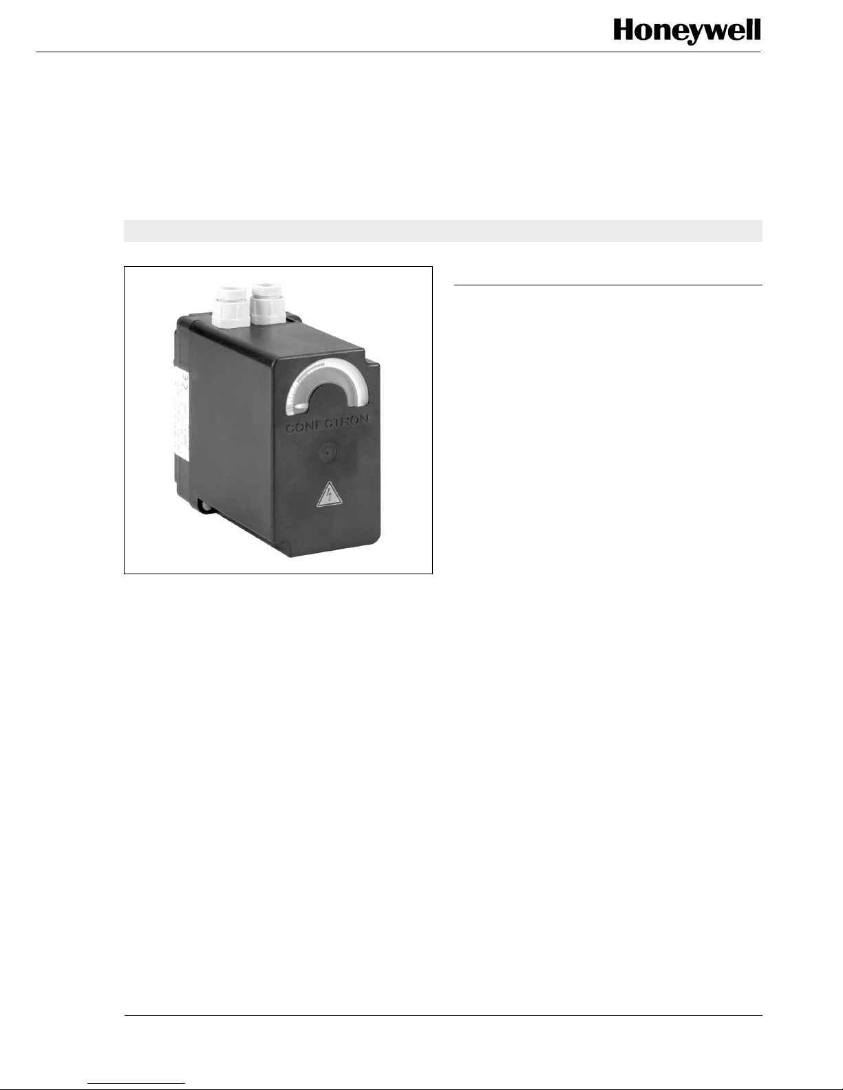
ACTUATOR
LKS 160
FOR AIR DAMPERS ON MULTI-STAGE AND
MODULATING BURNERS
CONTENTS
GENERAL
Description ................................................................. 2
Features ...................................................................... 2
TECHNICAL DATA
Specification ............................................................... 3
Dimensional drawings ................................................ 5
INSTALLATION AND OPERATION
Installation and final checkout .................................... 6
Citrcuit diagrams ........................................................ 7
VARIOUS
Standards and approvals ........................................... 9
Ordering information .................................................. 9
Accessories ................................................................ 9
APPLICATION
The LKS 160 air damper actuator is designed to be fitted to
multi-stage or modulating oil and gas burners with fully
closed position.

EN2C-0112SZ20 R0202 2
Electric actuator up to 3.0 Nm
• Drive times: 3 ... 65 sec.
• Variants: - clockwise or counter clockwise rotation
- with integrated electronic circuitry
- shaft version
GENERAL
DESCRIPTION
A synchronous motor powers a drive shaft and a backlashfree cam shaft via a gear reducer.
The cam shaft operates limit and auxiliary switches. The
position at which one of the limit or auxiliary switches operates
can be adjusted steplessly within the operating range using
the associated cam disc. Manually adjustable lever-operated
cams or spindle-driven cams, which can be adjusted with a
screwdriver, are available.
FEATURES
• Position indicator
• Easily adjustable limit and auxiliary switches
• Synchronous motor

3 EN2C-0112SZ20 R0202
Diagram Shaft Drive Load torque Holding Voltage Type Remarks
time torque
Nr. Nr. s Nm Nm V
S1 5 5 2,5 0,8 230 LKS 160-01 A 5-5 S1 standard version
S2 5 5 2,5 0,8 230 LKS 160-03 A 5-5 S2 standard version
S1 5 12 3 1,5 230 LKS 160-07 A 5-12 S1
S1 5 5 2,5 0,8 230 LKS 160-09 A 5-5 S1 Spindle-driven cam
S7 5 30 3 3 24 LKS 160-22 A 5-30 S7
S7.1 5 30 3 3 110 LKS 160-24 A 5-30 S7.1
S6 5 34 3 3 230 LKS 160-25 A 5-34 S6
S1.2 5 34 3 3 230 LKS 160-26 A 5-34 S1.2
S1 5 12 3 1,5 230 LKS 160-37 A 5-12 S1
S4 5 5 2,5 0,8 230 LKS 160-39 A 5-5 S4
S2 5 3 1,5 0,6 230 LKS 160-40 A 5-3 S2
S13 5 45 3 3 230 LKS 160-42 A 6-45 S13 Spindle-driven cam
S8.P1.1 5 34 3 3 230 LKS 160-44 A 5-34 S8.P1.1 Potentiometer can be retrofitted
S8.P2 5 30 3 3 110 LKS 160-55 A 5-30 S8.P2 Potentiometer can be retrofitted
S8.P4 5 45 3 3 230 LKS 160-59 A 5-45 S8.P4 with Potentiometer, special circuit
S8.P 6 34 3 3 230 LKS 160-63 A 6-34 S8.P Potentiometer can be retrofitted
S8.P4.1 5 38 3 3 120 LKS 160-65 A 5-38 S8.P4.1 Run time at 60 Hz, with Potentiometer,
special circuit
S8.P3 5 30 3 3 24 LKS 160-67 A 5-30 S8.P3 Potentiometer can be retrofitted
S8.P1.1 5 34 3 3 230 LKS 160-68 A 5-34 S8.P1.1 Potentiometer can be retrofitted,
spindle-driven cam
S8.P1 5 5 2,5 0,8 230 LKS 160-70 A 5-5 S8.P1
S4 5 3 1,5 0,6 230 LKS 160-73 A 5-3 S4
S15 5 5 2,5 0,8 230 LKS 160-75 A 5-5 S15 For 3-stage operation
S2 5 12 3 1,5 230 LKS 160-79 A 5-12 S2
2) 3)
4)
6)
5)
7)
1)
SPECIFICATION
TECHNICAL DATA
Type overview
clockwise rotation
Legend
1) when viewing from direction A (see dimensional drawing)
2) see “Circuit diagrams”
3) see “Dimensional drawing”
4) at 50 Hz for 90°
at 60 Hz, Drive times are about 20 % shorter
5) under nominal conditions
under extreme conditions (e.g. +60 °C, 230V -15%) the torques will be 25% lower
6) +10% -15%; 50...60Hz
at -15%; torque reduced by approx. 20% at undervoltage
7) Standard: Lever-operated cam
 Loading...