

Honeywell LKPES8M-EN Installation Instructions Manual
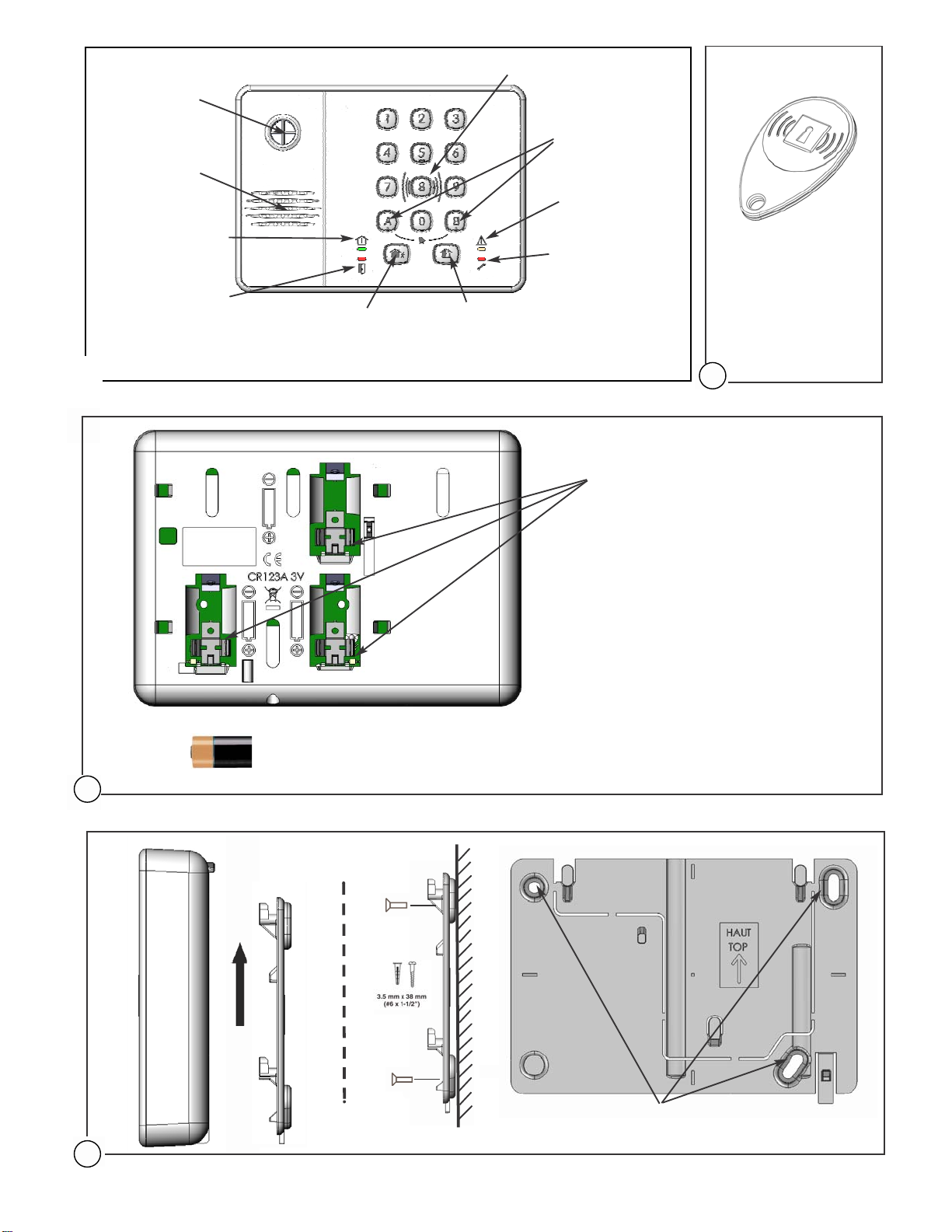
Siren output
Audio output
System armed LED
Intruder alarm LED
(LED1)
(LED4)
Total set arming key
T ag reader: identif ication area
SOS keys
System fault LED
Tamper alarm LED
Partial set arming key
(LED2)
(LED3)
TAG
3
Product descripti
3
x
(CR123A)
on
Battery Replacemen
2
Place one battery in each one of the
3 battery holders (read carefully the
battery replacement instructions on
page 1 before)
BATTERY REMOVAL AND HANDLIN G SAFETY
WARNING Risk of fire, explosion and burns, do not
recharge, disassemble, heat above 100° C, or
incinerate the battery. While the battery can normally
be safely removed by hand, care should be used to
ensure that the battery terminals are not shorted, nor
the battery damaged, during the removal process.
Dispose of depleted batteries by complying with
applicable national and local regulations. In the event
of the battery being damaged, us e pers o nal
protective equipment to remove it immediat ely, and
dispose of it in a safe manner (refer to the battery
manufacturer’s specifications for such situations).
For Switzerland, Annex 2.15 of SR 814.81 applies to
the battery include d with this product.
t
4
M
- 1 -
ounti
ng
Mounting holes
© 2010 Honeywell International, Inc.

LKPES8M-EN
- Installation Instruction
s
Wireless Aud io keypad w ith integrated tag rea der and
siren
Introduction
The LKPES8M-EN is designed to control the
DOMONIAL 7/7G panel’s series. The primary
function of this fully wireless keypad is to arm and
disarm the system. This can be done either by
entering a code on the numeric keypad or by using
the integrated proximity tag reader. The LKPES8MEN also features an integrated siren and can be used as a remote audio
verification device between the monitoring station and the protected area.
Mounting
The keypad must be installed on its mounting bracket and is not meant to be
used outside its bracket. This bracket must be fixed on a wall and easily
accessible for the arming and disarming of the system.
Mounting steps:
1) Separate the bracket from the keypad (see drawing 4 page 1)
2) Fix the bracket on the wall using screws (see drawing 4 page 1)
3) Insert the battery keeping the polarities.
4) Put the keypad back in its bracket.
5) Depending on the regulation in force in the country, the keypad could be
secured in its bracket with the supplied screw.
Registeri
The registering is the procedure associating the keypad to the panel. This
operation requires a programming tool. The complete procedure
is described in the alarm central unit installation notice or in the programming
tool manual.
Up to 2 audio keypads can be used per installation and up to 3 keypads if the
audio functionality is disabled.
1) Connect the programming tool and start programming.
2) Go to the « Register » menu and put the panel into registration mode.
3) To register the keypad, insert the batte ries or remove the keypad from its
mounting bracket to trigger a tamper fault or trigger an alert by pressing
simultaneously and keys (see page 1). Depending on the
configuration of the panel, the keypad and panel will beep to confirm the
registration.
4) Configure the keypad in the programming tool:
5) Get out of programming mode
IMPORTANT: The keypad must always be prog ra mme d i n it s f ina l
location with a minimum radio level of 3 units on a scale of 10
ng
- Set label of the device
- Choose alert mode (1: silent, 2: beep or 3: siren)
- Choose associated set (Total, Annex or Total + Annex)
Power and Maintenance
The keypad signals a battery failure at the control panel when the
battery needs to be replaced. LED2 will light on to signal locally to the end
user the battery default (see drawing 1 page 1). The keypad will continue to
operate for up to one month after this event. Replace battery with CR123A 3V
Lithium battery type only.
To replace the battery follow the procedure described bellow:
1) Remove the keypad from its mounting bracket.
2) A tamper alarm is sent to the panel. There is a 120-seconds delay
(depending on panel configuration) before transmitting the specific tamper
message to the monitoring station. If tamper is restored before the end of
the delay, no transmission will occur. (The tamper delay is only when the
system is disarmed. Tamper is immediately transmitted if the panel is
armed)
3) Remove the batteries and replace them with new batteries from the same
type
4) Put the keypad back on the bracket
To clean the
keypad,
use a dry clo th only (no det
ergent).
Programming the Keypad (Installer mode)
The keypad features 2 programming modes which allow the installer and end
user to control the keypad functionalities.
The procedure bellow explains the procedure to enter the installer
programming mode. For details on the end user’s programming mode please
- 2 -
refer to the user’s manual.
To enter installer’s programming mode:
1) Press simultaneously keys and more than 3 seconds
and release them.
A double beep is played and all LEDs light up.
2) Enter installer’s code
All LEDs start flashing and a long beep is played
To exit installer’s programming mode and save your
changes:
1) Press to exit programming and save your
changes
All LEDs stop flashing and a double beep is played.
Note: The system will automatically exit programming mode after
20 seconds if no keys are pressed during this period. If this occurs, you
must repeat all the steps necessary for the function you are using.
In programming mode, it is possible to:
Set arming with id entification:
1. Press to select function
2. Press to activate arming with identification (code or TAG)
Set quick arming:
1. Press button to select function
2. Press to activate quick arming
Associate a TAG to a user:
1. Press a numeric key to select user’s number [ 0…9 ]
2. Present the TAG
Note: The keypad will automaticall y g et out of programming mode if the
TAG is already registered. If the user already has a TAG, it is replaced by
the new one
.
Change a user’s code:
1. Press a numeric key to select user’s number [ 0…9 ]
2. Enter new user’s code
3. Re-enter new user’s code
Disable a user’s code (disable the code for a user an d kee p
the TAG only):
1. Press a numeric key to select user’s number [ 0…9 ]
2. Enter 0000 (or 000000 if 6 digits)
3. Re-Enter 0000 (or 000000 if 6 digits)
4. Press
Disable a user:
1. Press a numeric key to select user’s number [ 0…9 ]
2. Press to disable the user
Enable a user:
1. Press “0 to 9” button to select user’s number
2. Press to enable the user
Note: it is possible to set a code and/or a tag to each user. The keyp ad
can have up to 10 users. The keypad can also be programmed to manage
4-digit or 6-digit codes (using p r ogramming tool).
Audio Configuration
The wireless audio verification functionality is configured from the
programming tool. Please refer to the programming tool documentation to
obtain further details
 Loading...