

Honeywell Limitless WMPR Installation And Technical Manual

Installation and Technical Manual for the
Limitless™ MultiProtocol Receiver,
Issue B
WMPR Series
m WARNING
PERSONAL INJURY
DO NOT USE these products as safety or emergency stop
devices or in any other application where failure of the
product could result in personal injury.
Failure to comply with these instructions could result in
death or serious injury.
m WARNING
Honeywell does not recommend using devices for critical
control applications where there is, or may be, a single point
of failure or where single points of failure may result in an
unsafe condition. It is up to the end-user to weigh the risks
and benefits to determine if the products are appropriate for
the application based on security, safety and performance.
Additionally, it is up to the end-user to ensure that the control
strategy results in a safe operating condition if any crucial
segment of the control solution fails. Honeywell customers
assume full responsibility for learning and meeting the
required Declaration of Conformity, Regulations, Guidelines,
etc. for each country in their distribution market.
Failure to comply with these instructions could result in
death or serious injury.
32309669
m WARNING
The WMPR must be installed in accordance with the
requirements specified in this document in order to
comply with the specific Country Communication Agency
requirements (i.e., FCC, IC, ACMA, etc.). See Section 3 as this
requires choosing the correct Country Use Code and thus
allowable antenna and/or cable usage.
, CAUTION
Power to the WMPR should not be applied during installation
of an antenna as damage could occur to the WMPR
electronics.
m WARNING
• The cable length of the customer-supplied dc power
source to the WMPR supply terminals cannot exceed
three (3) meters.
• The WMPR must be used indoors.
• The WMPR must be used inside a cabinet and can only
be accessed during set-up or maintenance.
m WARNING
RF EXPOSURE
To satisfy FCC RF exposure requirements for mobile
transmitting devices, a separation distance of 20 cm or more
should be maintained between the antenna of this device
and persons during device operation To ensure compliance,
operation at closer than this distance is not recommended.
The antenna used for this transmission must not be colocated in conjunction with any other antenna or transmitter.
Failure to comply with these instructions could result in
death or serious injury.
Sensing and Internet of Things

Installation and Technical Manual for the
ISSUE B
Limitless™ Multi-Protocol Receiver, WMPR Series
TABLE OF CONTENTS
1 PRODUCT DESCRIPTION.............. 1
1.1 General ....................................1
1.2 Principle of Operation......................1
1.3 Product Nomenclature.....................2
1.4 Abbreviations & Definitions ................3
1.5 Symbols & Definitions......................4
2 SPECIFICATIONS, CERTIFICATIONS,
AND APPROVALS ..................... 5
2.1 Intended County Usage ....................5
2.2 Certifications and Approvals ...............5
2.3 Radio Module Specifications...............5
2.4 Electrical Specifications....................5
2.5 Operational Characteristics ................6
2.5.1 Update Rate vs. Node Quality ..........6
2.5.2 Update Rate vs. RF Lost Indication .....6
2.6 EMC Specifications ........................6
2.7 Environmental Specifications ..............6
2.8 Weight .....................................6
2.9 Antenna Connection .......................6
2.10 Agency Compliance Statements ...........6
2.10.1 FCC Compliance Statements...........6
2.10.2 IC Compliance Statements .............7
2.10.3 RF Safety Statements (FCC & IC).......7
3 WMPR FEATURES..................... 8
3.1 LED Indicator ..............................8
3.2 Limitless™ Switch and Sensor Buttons .....9
4 R.F. INTERFER. CONSIDERATIONS .....10
4.1 RF Interference Considerations ...........10
4.1.1 General................................10
4.1.2 WiFi Networks .........................10
4.1.3 Smart Phone “Apps” ...................10
4.1.4 Bluetooth® Devices ....................10
4.1.5 Wireless Video Camera & Links........10
4.1.6 Microwave Ovens .....................10
4.1.7 Cordless Phones/Baby Monitors ......10
5 SETUP AND ELECTRICAL
CONFIGURATIONS ...................11
5.1 System Set Up ............................11
5.1.1 WMPR EDS File .......................11
5.1.2 WMPR Object Model ..................11
5.2 Static IP Address (ON/OFF DHCP Server) 11
5.3 EtherNet/IP™ Output Connection.........11
5.3.1 Description............................11
5.4 Power Supply Connections................12
5.4.1 Description............................12
6 LCD/MENU/MODE OPERATION .....12
6.1 Start-up or Re-start-up Mode .............12
6.1.1 Zero Switches or Sensors Paired.......12
6.1.2 One or More Switches or Sensors .....12
6.2 Main Menu................................13
6.2.1 Menu Status ..........................13
6.2.2 EtherNet/IP™ Connection .............13
6.2.3 Node Information .....................14
6.3 Node Status...............................14
6.3.1 Node Status Menu ....................14
6.4 Action Menu ..............................14
6.4.1 Action Menu ..........................14
6.5 Node Detail ...............................15
6.5.1 Node Detail Menu, Screen 1...........15
6.5.2 Node Detail Menu, Screen 2...........15
6.5.3 Node Detail Menu, Screen 3...........16
6.6 Configuration Menu ......................16
6.7 Receiver Detail ............................17
6.8 Pair Mode .................................17
6.9 Purge Mode ...............................19
6.10 Node Update Rate Mode ..................19
6.11 Node LCD Display Mode ..................20
6.12 Factory Reset Receiver Mode, GEN 1......21
6.13 Factory Reset Receiver Mode, GEN 2......22
6.13.1 Reset all Nodes from WMPR ..........22
7 ANTENNA, CABLING, & MOUNTING .. 23
7.1 Approved Antenna Options................23
32309669
ii sensing.honeywell.com

Installation and Technical Manual for the
ISSUE B
Limitless™ Multi-Protocol Receiver, WMPR Series
8 ANTENNA SELECTION,
ADJUSTMENT & MOUNTING .........25
8.1 Warnings..................................25
8.2 Antenna Designs & Considerations .......26
8.2.1 Omni-directional Antenna Design.....26
8.3 Antenna Mounting & Considerations .....27
8.3.1 Mounting to RF Signal ................27
8.4 Antenna Options ..........................28
8.5 Antenna Connections & Options ..........29
8.5.1 Antenna Connection ..................29
8.5.2 Cable Requirement....................30
8.5.3 Antenna Styles & Mounting Options ..30
8.5.4 Antenna Adjustment Considerations ..31
8.5.5 Grounding Remote Antennas .........32
8.6 Antenna Environmental Usage............33
8.6.1 Meet Application Exposure Conditions 33
8.6.2 Protection of Antenna Connections ...33
8.6.3 Outdoor Antenna Installations ........34
8.6.4 Lightning Arrestor.....................34
8.6.5 Site Selection..........................34
8.6.6 Mounting in Respect to Location......34
8.7 Gain with Acceptable FadeMargin........34
9 WMPR MOUNTING...................36
9.1 DIN Rail Mounting ........................36
9.2 Tab Mounting .............................36
10 INSPECTION AND MAINTENANCE ... 36
10.1 WMPR Inspection and Replacement ......36
10.2 Antenna Inspection and Replacement ....36
11 CHOOSING A CATALOG LISTING .....37
12 QUICK START UP AND INSTALLATION 37
13 ACCESSORIES .......................38
14 INSTALLATION DRAWING ............40
32309669
Sensing and Internet of Things iii

Installation and Technical Manual for the
ISSUE B
Limitless™ Multi-Protocol Receiver, WMPR Series
List of Figures
Figure 1. WMPR Series Nomenclature ....................... 2
Figure 2. Limitless™ WMPR with Callouts .................... 8
Figure 3a. Limtless™ WBX Function Button and LED ......... 9
Figure 3b. Limtless™ WLS Function Button and LED ......... 9
Figure 3c. Limtless™ WPS Reset Button and LED ............. 9
Figure 4. Honeywell Splash Screen .........................12
Figure 5. EtherNet/IP™ MAC ID & IP Address ...............12
Figure 6. Main Menu .......................................12
Figure 7. Honeywell Splash Screen .........................12
Figure 8. System Start Up ..................................13
Figure 9. EtherNet/IP™ MAC ID & IP Address ...............13
Figure 10. Main Menu .......................................13
Figure 11. Main Menu .......................................13
Figure 12. Main Menu - Ethernet Lost .......................13
Figure 13. Main Menu - RF Lost Screen Display .............14
Figure 14. Node Status ......................................14
Figure 15. Action Menu ......................................14
Figure 16. Node Detail Menu ................................15
Figure 17. Node Detail, Screen 1 .............................15
Figure 18. Node Detail, Screen 2 .............................15
Figure 19. Node Detail, Screen 3 .............................16
Figure 20. Configuration Menu ..............................16
Figure 21. Configuration Menu, continued ..................16
Figure 22. Receiver Detail Menu .............................17
Figure 23. Receiver Information, Screen 1 ...................17
Figure 24. Receiver Information, Screen 2 ...................17
Figure 25. Pair Mode .........................................17
Figure 26. Pairing in Progress ................................18
Figure 27. Join Network Notice (switch) .....................18
Figure 28. Join Network Notice (Analog sensor) .............18
Figure 29. Purge Mode ......................................19
Figure 30. Purge Mode - Purge Update Sent .................19
Figure 31. Purge Mode - Single Node Being Purged .........19
Figure 32. Purge Mode - Multiple Nodes Being Purged ......19
Figure 33. Node Update Rate Mode. . . . . . . . . . . . . . . . . . . . . . . . . . 19
Figure 34. Node Update Rate - Update Rate in Progress .....20
Figure 35. Node Update Rate - Update Rate Displayed ......20
Figure 36. Node Update Rate - Changed Update Rate .......20
Figure 37. Node LCD Display Mode ..........................20
Figure 38. Node LCD Time ...................................20
Figure 39. Node LCD Time - Time Displayed .................21
Figure 40. Node LCD Time - Updated LCD Time .............21
Figure 41. Factory Reset Mode ..............................21
Figure 42. Reset of Receiver, GEN 1 only .....................21
Figure 43. Network Start Notice. . . . . . . . . . . . . . . . . . . . . . . . . . . . . . 21
Figure 44. Reset of Receiver, GEN 2 only .....................22
Figure 45. Radiation Pattern/Omni-directional Antenna .....26
Figure 46. LOS Free From Obstacles .........................27
Figure 47. LOS Affected by Obstacles ........................27
Figure 48. Limitless™ RPSMA Connection, Direct ...........29
Figure 49. Limitless ™ RPSMA Connection, Remote .........29
Figure 50. Adhesive Mounting Steps .........................30
Figure 51. Mast Mount Antenna .............................31
Figure 52. Mast Mount Antenna, Side View ..................31
Figure 53. Magnetic Base Mount Antenna ...................31
Figure 54. Magnetic Mount Antenna ........................31
Figure 55. Magnetic Mount Antenna ........................31
Figure 56. Thru-hole Mount Antenna ........................31
Figure 57. Highest RF Signal Diagram .......................32
Figure 58. Application of Protective Tape ....................33
Figure 59. Limitless™ WMPR DIN Rail Bracket ...............36
Figure 60. Limitless™ WMPR Mounting Plate ................36
Figure 61. WMPR Series Nomenclature ......................37
Figure 62. WMPR Dimensions ...............................40
List of Tables
Table 1. Abbreviations ......................................3
Table 2. Symbol Definitions ................................ 4
Table 3. North America: Country Code Use “A” .............. 5
Table 4. Asia Pacific: Country Code Use “B” ................. 5
Table 5. Communication Approvals and Standards ......... 5
Table 6. Radio Module Specifications ...................... 5
Table 7. Electrical Specifications ........................... 5
Table 8. WPS Series Sensors Update Rate .................. 6
Table 9. WBX Series Switches Update Rate ................. 6
Table 10. Update Rate vs. RF Lost Indication ................6
Table 11. Environmental Specifications ..................... 6
Table 12. LED Indicators ..................................... 8
Table 13. Conformance Advisories & Warnings .............11
Table 14. Node Display and Indication ......................14
Table 15. Node Display and Indication, Screen 1 ...........15
Table 16. Node Display and Indication, Screen 2 ...........15
Table 17. Node Display and Indication, Screen 3 ...........16
Table 18. Receiver Detail and Display, Screen 1 .............17
Table 19. Receiver Detail and Display, Screen 2 .............17
Table 20. Pair Mode .........................................18
Table 21. Country Code Use “A” Options ....................23
Table 22. Country Code Use “B” Options ....................24
Table 23. Antenna Options ..................................28
Table 24. Grounding the Antenna ...........................32
Table 25. Suggested StartUp Sections to Review ..........37
Table 26. Limitless™ Antennas ..............................38
Table 27. Limitless™ Cables .................................39
Table 28. Limitless™ Base Accessories ......................39
32309669
iv sensing.honeywell.com

Installation and Technical Manual for the
ISSUE B
Limitless™ Multi-Protocol Receiver, WMPR Series
Intended Audience
This guide is intended for people who are responsible for planning, configuring, administering, and operating the Limitless™
Network.
Prerequisite Skills
It is assumed that you are familiar with the operation of Limitless™ Networks.
About this Document
This document outlines professional installation requirements
for the Limitless™ Receiver, WMPR Series. Professional installation is required to comply with certification agency and legal
requirements. This document must be adhered to for all installations of the Limitless™ Receiver, WMPR Series.
These devices are not intended for critical control where there
is a single point of failure or where single points of failure result
in unsafe conditions. As with any process control solution, it
is the end users’ responsibility to weigh the risks and benefits
to determine if the products used are the right match for the
application based on security, safety, regulations, and performance.
References
The following list identifies all documents that may be sources
of reference for material discussed in this publication.
1 | PRODUCT DESCRIPTION
1.1 | General
The Limitless™ Series uses the latest commercial off-theshelf wireless technology that can be used in a wide variety
of applications. This is especially beneficial for remote
monitoring applications where previous wiring installation or
wire maintenance was not physically possible or economically
feasible. This document will provide installation instructions to
properly install a Limitless™ Wireless MultiProtocol Receiver
WMPR, as well as a detailed understanding of its functions.
1.2 | Principle of Operation
A Limitless™ input sends an RF signal to the WMPR when
the Limitless™ digital or analog input changes state. There
may be up to 14 Limitless™ digital or analog inputs that
communicate and indicate their state to a single WMPR. The
WMPR receiver is menu driven through the use of function
buttons and a easy to read LCD display. The menu allows you to
see status of the nodes, configure nodes, and update receiver
functionality. A change of state of a Limitless ™ input will cause
a corresponding change in output of the particular node to be
output via an EtherNet/IP™ output. The WMPR indicates low
battery conditions, lost RF links, as well as other diagnostic and
functional operations described in further detail throughout
this manual.
32309669
Document title Document No. Product Usage
WMPR0003000700100100.eds Contact Honeywell GEN code Version 1 only
WMPR0003000700100100_V210.eds Contact Honeywell GEN code Version 2 only
Limitless™ WMPR Series Wireless MultiProtocol
Receiver EtherNet/IP™ Object Model
32308916 ALL
Sensing and Internet of Things 1

Installation and Technical Manual for the
Multi-Protocol
Specials
ISSUE B
Limitless™ Multi-Protocol Receiver, WMPR Series
1.3 | Product Nomenclature
This document is valid for the Limitless™ Receiver, WMPR Series in the following variations.
Figure 1. Limitless™ Receiver, WMPR Series Nomenclature
WMPR
Receiver type
WMPR Series
Receiver
1
GEN code
Version 1
1
Version 2*
2
*GEN code 2 is not ODVA certfied due to programming allowing a static (permanently assigned) IP address.
A
A
RF code
2.4 GHz;
IEEE 802.15.4
00
Antenna
type code
No antenna; RP-SMA
00
connector jack
2.2 dBi omni w/receiver
02
mount; tilt/swivel
A
Country use
code
US,
A
Canada
All other
approved
B
countries
1
Output code
EtherNet/IP™
1
A
Seal code
IP20
A
32309669
1
Mounting
code
Mounting
plate, epoxy
1
coated CRS
DIN
bracket,
2
aluminum
2 sensing.honeywell.com

Installation and Technical Manual for the
ISSUE B
Limitless™ Multi-Protocol Receiver, WMPR Series
1.4 | Abbreviations and Definitions
Table 1. Abbreviations
ACMA Australian Communications and Media Authority
CRS Cold-rolled steel
dB Decibel
dBi Decibel Isotropic
dBm Decibel above or below 1 milliwatt
DSSS Direct Sequence Spread Spectrum
EIRP Equivalent isotropic radiated power
EMC Electromagnetic Compatibility
ETSI European Telecommunications Standards Institute
EU European Union
FCC Federal Communications Committee
ft-lb Foot-pounds
GHz GigaHertz
IC Industry Canada
ICES Industry Canada Electrical Specification
IEEE Institute of Electrical and Electronics Engineers
IP Internet Protocol
ISO International Organization of Standardization
kbps KiloBits Per Second
LED Light Emitting Diode
MAC ID Media Access Control address
MHz MegaHertz
MPE Maximum Permissible Exposure
NA North America – United States of America and Canada
NEMA National Electrical Manufacturers Association
ODVA Open DeviceNet Vendors Association
R&TTE Radio and Telecommunications Terminal Equipment
RPSMA Reverse Polarity SMA connector
RF Radio Frequency
RSS Radio Standards Specifications
TX Transmit Power
WBX Wireless Hazardous Area Limit Switch
WDRR Wireless DIN Rail Receiver
WGLA Wireless Global Limit Switch Series
WLS Wireless Limit Switch
WMPR Wireless MultiProtocol Receiver
WOI Wireless Operator Interface
WPS Wireless Pressure Sensor
32309669
Sensing and Internet of Things 3
Installation and Technical Manual for the
ISSUE B
Limitless™ Multi-Protocol Receiver, WMPR Series
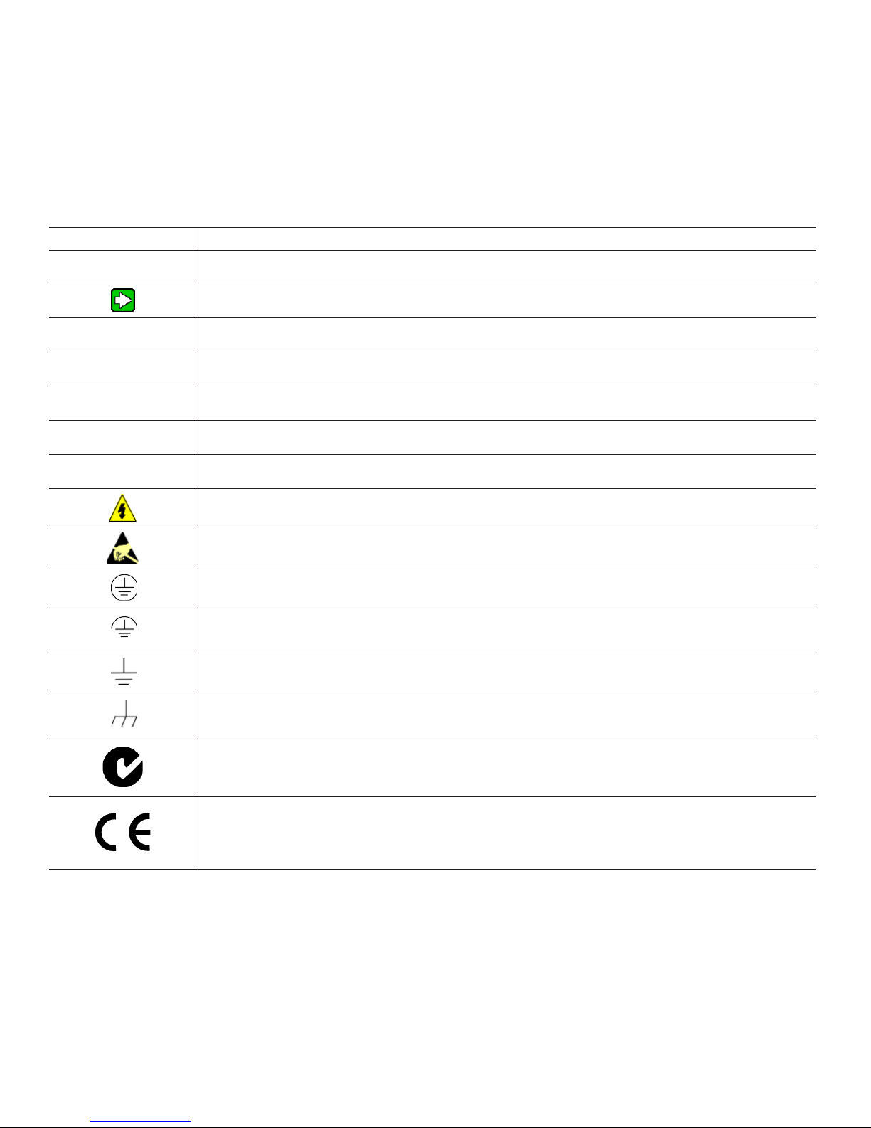
1.5 | Symbol Definitions
The following table lists those symbols used in this document to denote certain conditions.
Table 2. Symbol Definitions
Symbol
,
CAUTION
m
m
m
m
Definition
ATTENTION: Identifies information that requires special consideration.
TIP: Identifies advice or hints for the user, often in terms of performing a task.
Indicates a situation which, if not avoided, may result in equipment or work (data) on the system being
damaged or lost, or may result in the inability to properly operate the process.
CAUTION: Indicates a potentially hazardous situation which, if not avoided, may result in minor or
moderate injury. It may also be used to alert against unsafe practices.
CAUTION symbol on the equipment refers the user to the product manual for additional information.
The symbol appears next to required information in the manual.
WARNING: Indicates a potentially hazardous situation, which, if not avoided, could result in serious
injury or death.
WARNING symbol on the equipment refers the user to the product manual for additional information.
The symbol appears next to required information in the manual.
WARNING, Risk of electrical shock: Potential shock hazard where HAZARDOUS LIVE voltages greater
than 30 Vrms, 42.4 Vpeak, or 60 Vdc may be accessible.
32309669
ESD HAZARD: Danger of an electrostatic discharge to which equipment may be sensitive. Observe
precautions for handling electrostatic sensitive devices.
Protective Earth (PE) terminal: Provided for connection of the protective earth (green or green/yellow) supply system conductor.
Functional earth terminal: Used for non-safety purposes such as noise immunity improvement.
NOTE: This connection shall be bonded to Protective Earth at the source of supply in accordance with
national local electrical code requirements.
Earth Ground: Functional earth connection. NOTE: This connection shall be bonded to Protective
Earth at the source of supply in accordance with national and local electrical code requirements.
Chassis Ground: Identifies a connection to the chassis or frame of the equipment shall be bonded to
Protective Earth at the source of supply in accordance with national and local electrical code requirements.
CTick Mark. The CTick Mark is a certification trade mark registered to ACMA (Australian Communications and Media Authority) in Australia under the Trade Marks Act 1995 and to RSM in New Zealand
under section 47 of the NZ Trade Marks Act. The mark is only to be used in accordance with conditions
laid down by ACMA and RSM. This mark is equal to the CE Mark used in the European Union.
Notified Body. For radio equipment used in the European Union in accordance with the R&TTE Directive, the CE Mark and the notified body (NB) identification number is used when the NB is involved in
the conformity assessment procedure. The alert sign must be used when a restriction on use (output
power limit by a country at certain frequencies) applies to the equipment and must follow the CE marking.
4 sensing.honeywell.com
Installation and Technical Manual for the
ISSUE B
Limitless™ Multi-Protocol Receiver, WMPR Series
2 | SPECIFICATIONS,
CERTIFICATIONS, AND APPROVALS
2.1 | Intended Country Usage
Table 3. North America; Country Code Use “A”
Country ISO 3166 2 letter code
UNITED STATES US
CANADA CA
Table 4. Asia Pacific; Country Code Use “B”
Country ISO 3166 2 letter code
AUSTRALIA AU
, ATTENTION
Contact Honeywell before use of the WMPR in countries not
listed in Tables 3 and 4.
2.2 | Certifications and Approvals
See product labels for applicable approvals and ratings.
Table 5. Communication Approvals and Standards
Approval/Item Ratings/Descrip-
tion
Enclosure type IP20
Federal Communications Commission
(FCC)
Industry Canada (IC)
Australian Communications and
Media Authority (ACMA)
EtherNet/IP™
General purpose discrete I/O
(GEN code Version 1 only)
FCC Part 15.247:
2014
Canadian RSS210:
2010
CTick mark
ODVA conformant™
m WARNING
• The cable length of the customer-supplied dc power
• The WMPR must be used indoors.
• The WMPR must be used inside a cabinet and can only
2.3 | Radio Module Specifications
Table 6. Radio Module Specifications
Item Specification
Radio module Honeywell RFPCBa
Wireless standard
Data rate 250 kbps
Operating
frequency
Module transmit
power
Receive sensitivity
(typ.)
# of pairing (max.)
2.4 | Electrical Specifications
Table 7. Electrical Specifications
Item Specification
Supply voltage 10 Vdc to 30 Vdc
Supply current 500 mA max.
Output type EtherNet/IP™
Termination Cage-clamp connector block
32309669
source to the WMPR supply terminals cannot exceed
three (3) meters.
be accessed during set-up or maintenance.
WPAN IEEE 802.15.4 Direct Sequence Spread Spectrum (DSSS), 2.4
GHz
ISM 2.4 GHz
Country use code “A”
Power level, 11 dBm
Country use code “B”
Power level, 6 dBm
100 dBm
Up to 14 Limitless™ inputs can be
paired to a single WMPR
m WARNING
The WMPR must be installed in accordance with the
requirements specified in this document in order to
comply with the specific Country Communication Agency
requirements. (i.e. FCC, IC, ACMA, etc.) See Section 3 as it
requires choosing the correct Country Use Code and thus
allowable antenna and/or cable usage.
m WARNING
The cable length of the customer-supplied dc power source
to the WMPR’s supply terminals cannot exceed three (3)
meters.
Sensing and Internet of Things 5

Installation and Technical Manual for the
ISSUE B
Limitless™ Multi-Protocol Receiver, WMPR Series
2.5 | Operational Characteristics
2.5.1 | Update Rate vs. Node Quantity
To ensure suitable performance the tables below define the
maximum number of nodes that are allowed with all nodes
being at the defined Update Rate:
Table 8. WPS Series Sensors Update Rate
Update Rate (seconds) # of Nodes
0.1 4
0.25, 0.5 6
> 1 14
Table 9. WBX Series Switches Update Rate
Update Rate (seconds) # of Nodes
> 1 14
Limitless™ WLS, WGLA, WOI Series switches cannot have the
update rate changed and are factory set at 30 seconds; number
of nodes: 14.
2.5.2 | Update Rate vs. RF Lost Indication
Table 12 displays the approximate amount of time it takes
for the WMPR to indicate a Node Lost RF with respect to the
Update Rate that the Node is set to.
Table 10. Update Rate vs. RF Lost Indication
Update Rate (sec) RF Lost Indication (approx. sec)
0.1 0.5
0.25 1
0.5 2
1 5
5 18
10 45
30 120
90 360
2.6 | EMC Specifications
The latest applicable EMC Standards are as follows:
• EN 300 328, V1.8.1
• EN 613261 (2013)
• EN 301 4891, V1.9.2
• EN 301 48917, V2.2.1
2.7 | Environmental Specifications
Table 11. Environmental Specifications
Item Specification
Operating temperature 20 °C to 70 °C [4 °F to 158 °F]
Storage temperature 20 °C to 70 °C [4 °F to 158 °F]
Operating humidity 0 %RH to 100 %RH
Shock
Vibration
2.8 | Weight
All versions of the WMPR Series Receiver have an approximate
weight of 215 g [7.5 oz]. This weight does not include mounting
brackets/plates, remote cables, or antennas.
2.9 | Antenna Connection
Antennas connect to an RPSMA male connector on the upper
surface of the WMPR. Alternatively, a remote antenna and/or a
lightning arrestor may be connected to the RPSMA connector;
when ordered without any antenna fitted to the WMPR product.
2.10 | Agency Compliance Statements
2.10.1 | FCC Compliance Statements
32309669
IEC 60068227; half sine, 10 g,
6 ms, 3 axis
IEC 6006826; 10500 Hz w/ 0.35
mm – peak-to-peak, 58500 Hz – 5 g
• This device complies with Part 15 of FCC Rules and
Regulations. Operation is subject to the following two
conditions:
(1) This device may not cause harmful interference
and
(2) This device must accept any interference received,
including interference that may cause undesired
operation.
• This equipment has been tested and found to
comply with the limits for a Class B digital device,
pursuant to Part 15 of the FCC Rules. These limits are
designed to provide reasonable protection against
harmful interference in a residential installation.
This equipment generates, uses, and can radiate
radio frequency energy and, if not installed and used
in accordance with these instructions, may cause
harmful interference to radio communications.
Operation of this equipment in a residential area is
likely to cause harmful interference in which case the
user will be required to correct the interference at his/
her own expense.
6 sensing.honeywell.com

Installation and Technical Manual for the
ISSUE B
Limitless™ Multi-Protocol Receiver, WMPR Series
• Intentional or unintentional changes or modifications
must not be made to the WMPR unless under
the express consent of the party responsible for
compliance. Any such modifications could void the
user’s authority to operate the equipment and will void
the manufacturer’s warranty.
2.10.2 | Industry Canada (IC) Compliance
Statements
• To reduce potential radio interference to other users,
the antenna type and its gain should be chosen so
that the equivalent isotropic radiated power (EIRP)
is not more than that permitted for successful
communication.
• Operation is subject to the following two conditions:
(1) this device may not cause interference, and
(2) this device must accept any interference, including
interference that may cause undesired operation of
the device.
• This Class A digital apparatus has been tested and
found to comply with Canadian RSS210:2010.
• This radio transmitter (identify device by certification
number) has been approved by Industry Canada to
operate with the antenna types listed below with the
maximum permissiable gain indicated. Antenna types
not included in this list, have a gain greater than the
maximum gain indicated for that type, are strictly
prohibited for use with this device
- Antenna type approved for use: Omni
- Antenna gain (max.): 9 dBi
• Pour réduire les interférences radio potentielles aux
autres utilisateurs, le type d’antenne et son gain
doivent être choisis de telle sorte que l’équivalent
isotrope puissance rayonnée (PIRE) ne est pas
supérieure à celle permise pour une communication
réussie.
• Son fonctionnement est soumis aux deux conditions
suivantes:
(1) ce dispositif ne doit pas causer d’interférences et
(2) cet appareil doit accepter toute interférence, y
compris les interférences qui peuvent causer un
mauvais fonctionnement de l’appareil.
• Cet appareil numérique de classe A est conforme avec
Industrie Canada RSS 210: 2010.
2.10.3 | Radio Frequency (RF) Safety
Statements (FCC & IC)
To comply with FCC’s and Industry Canada’s RF exposure
requirements, the following antenna installation and device
operating configurations must be satisfied.
32309669
• Cet émetteur radio (appareil identifié par numéro de
certification) a été approuvé par Industry Canada
pour fonctionner avec les types d’antenne répertoriés
ci-dessous et présentant le gain maximal admissible
indiqué. Utiliser des types d’antennes non mentionnés
dans cette liste ou présentant un gain supérieur au
maximum indiqué pour ce type est strictement interdit.
- Type d’antenne approuvé : Toutes directions
- Gain d’antenne (max.) : 9 dBi
• Remote antenna for this unit must be fixed and
mounted on outdoor permanent structures with a
separation distance between any other antenna(s) of
greater than 20 cm [7.87 in] and a separation distance
of at least 20 cm [7.87 in] from all persons.
• Furthermore, when using an direct-mount antenna
with the WBX, it must not be co-located with any other
antenna or transmitter device and it must have a
separation distance of at least 20 cm [7.87 in] from all
persons.
Sensing and Internet of Things 7
Installation and Technical Manual for the
ISSUE B
Limitless™ Multi-Protocol Receiver, WMPR Series
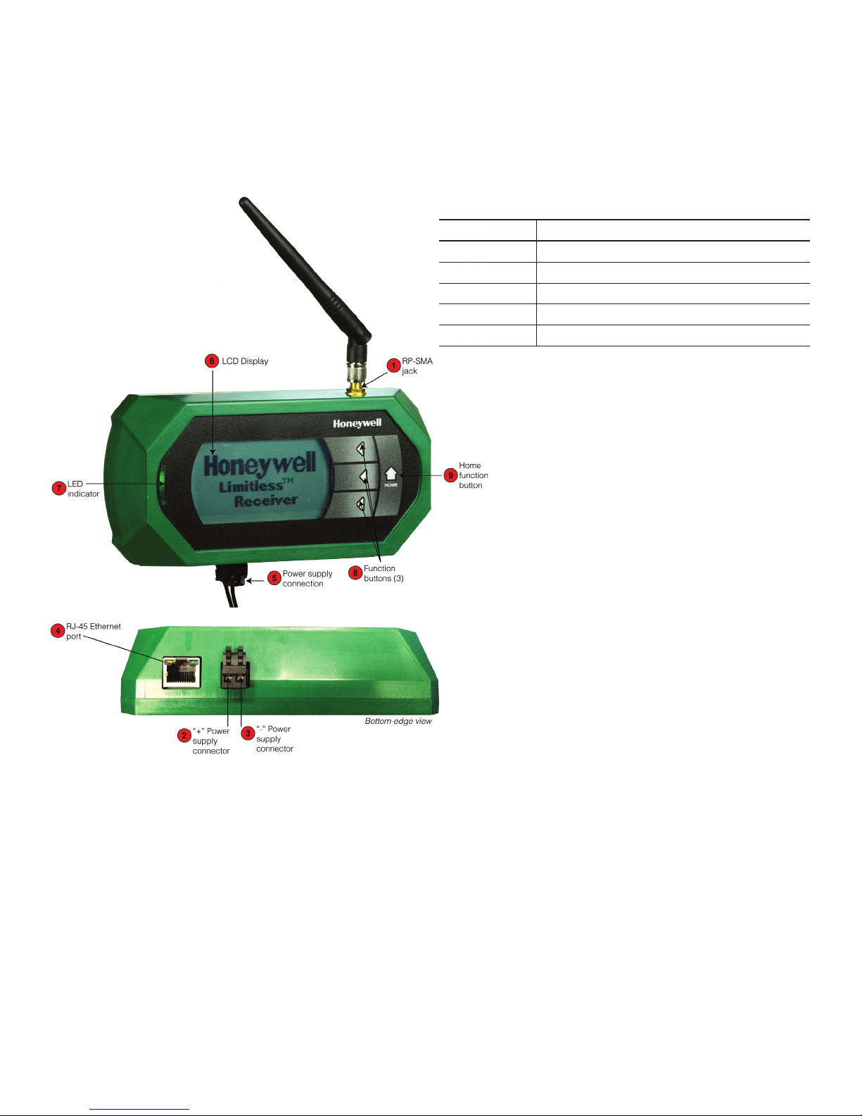
3 | WMPR FEATURES
Figure 2. Limitless™ WMPR MultiProtocol Receiver with
location call-out
3.1 | LED Indicator
The WMPR LED operates as follows (see Figure 2 7):
Table 12. LED Indications
LED Function Indication
Solid green Power supplied, system functioning normally
Flashing blue 1 or more nodes with low battery
Solid blue 1 or more nodes with lost RF
Flashing red EtherNet/IP™ lost connection
Solid red System fault
32309669
8 sensing.honeywell.com
Installation and Technical Manual for the
ISSUE B
Limitless™ Multi-Protocol Receiver, WMPR Series
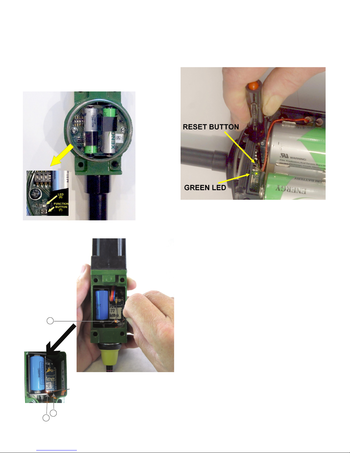
3.2 | Limitless™ Switch and Sensor
Function Buttons
Figure 3a. Limitless™ WBX: Function Button and LED
Figure 3c. Limitless™ WPS: Reset Button and LED
32309669
Figure 3b. Limitless™ WLS: Function Button and LED
7
7
8
Sensing and Internet of Things 9

Installation and Technical Manual for the
ISSUE B
Limitless™ Multi-Protocol Receiver, WMPR Series
4 | R.F. INTERFERENCE
CONSIDERATIONS
4.1 | R.F. Interference Considerations
4.1.1 | General
The 802.15.4 specification provides a high resistance to interference. Within the 2.4 GHz band, there are 16 channels, each
using approximately 2 MHz of bandwidth. The channel used
may be rapidly changed depending on the presence of other
signals sensed in that channel. Thus narrow band interfering
signals may have no effect, while broadband noise sources may
cause loss. The effect of light to moderate interference is not to
make the system fail, but to increase the rate of “lost packets” of
data. These “lost packets” are simply retransmitted as needed,
so the user may not notice any problem. More serious interference can cause loss of more data updates, and error messages
reported by the WMPR, as well as shorter battery life.
4.1.2 | WiFi Networks
Most WiFi (WLAN) networks operate in the same 2.4 GHz range
and use wider bands within that range. Also, the faster protocols (802.11N or AC), may utilize multiple channels. Factors affecting R.F. interference would be channel separation, distance
separation, and duty cycle.
• Channel separation: Studies have shown that a channel
separation of 7 MHz will make interference less likely. WiFi
routers can be set to use different channels as needed, and
auto channel modes can be disabled. If possible, switching to a 5 GHz-only protocol (using 802.11N or AC), would
eliminate any possibility of 2.4 GHz interference.
• Distance separation: A physical separation of 10 meters or
more will reduce possibility of interference.
• Duty Cycle: Generally the duty cycle of WiFi routers is very
low for simple uses as e-mailing, messaging, most web
browsing, and voice protocols. However, a video camera or
multiple users streaming video would cause a significant
increase in bandwidth usage and increase the possibility of
interference, making channel or distance separation more
desirable.
Regarding the WiFi client (laptop, smartphone, tablet), they are
much less of a problem as they generally operate with a much
reduced duty cycle (most data is received by the device), and
may operate with much lower transmit power
different. However, if a suspected interference source causes a
large reduction in consumer WiFi download speed, it is likely it
could also cause interference to the 802.15.4 data used by the
WMPR.
4.1.4 | Bluetooth® Devices
Bluetooth® interference is less of an issue, due to the very
narrow bandwidth of Bluetooth® signals, the low transmit
power, and the rapid “frequency hopping” of the signals. If the
802.15.4 device misses a packet of data due to a Bluetooth®
burst of data, the re-transmission of the 802.15.4 data will
likely succeed, as the Bluetooth® will have hopped to a different
channel by then.
4.1.5 | Wireless Video Camera and Video Links
Wireless video links operating in the 2.4 GHz band can cause
serious interference as they are operating continuously, use a
wide (6 MHz) bandwidth), and may be more powerful. Interference from wireless video could cause the “NO RF” indication in
severe cases. As mentioned, frequency and/or distance separation may be required.
• Frequency Separation: Many video links have four or more
• Distance Separation: Separating the video link sensor from
4.1.6 | Microwave Ovens
Microwave ovens operate in the 2.4 GHz range, they are powerful, and a high-duty cycle. However, they may not be a problem
to a modern 802.15.4 network. The magnetron in a microwave
oven is driven by half-wave rectified AC, so the R.F. output is
actually off for one half of the 60 Hz or 50 Hz power line cycle
(8.33 msec or 10.0 msec). During that part of the cycle, the
packets of 802.15.4 data may succeed. However, close to half
of the packets may require retransmission, so data throughput
could be greatly reduced.
32309669
channels selectable. Changing channels may help. Additionally, wireless video links are available in the 900 MHz
band, and the 1.2 GHz band. Switching to one of those
would eliminate interference issues with 802.15.4 (and
802.11x).
the WMPR would be very desirable. Alternatively, utilizing
directional antennas on the WMPR, and /or on the wireless
video link would help greatly.
4.1.3 | Smart Phone “Apps”
Smart phone “apps” are available to display consumer WiFi
signal strengths or download/upload speeds. These apps
will not display the 802.15.4 signals as the packet format is
10 sensing.honeywell.com
4.1.7 | Cordless Phones/Baby Monitors/
Intercoms
A 2.4 GHz cordless phone in very close proximity to a wireless
sensor could cause lost packets, while the phone is in use, but
is not a very likely cause. If suspected interference, a simple
remedy is to switch to a DECT 6.0 cordless phone operating on
1.9 GHz.
 Loading...