

Page 1
Quick Start
Guide for the
Limitless™ Series WDRR Receiver
50063986
WARNING
death or serious injury.
WARNING
in death or serious injury.
WARNING
• The WDRR must be installed in accordance with the
cable usage.
CAUTION
•
CAUTION
responses under simultaneous operation.
PERSONAL INJURY
• DO NOT USE these products as safety or emergency
stop devices or in any other application where failure of
the product could result in personal injury.
Failure to comply with these instructions could result in
Honeywell does not recommend using devices for critical
control applications where there is, or may be, a single point
of failure or where single points of failure may result in an
unsafe condition. It is up to the end-user to weigh the risks
and benefits to determine if the products are appropriate for
the application based on security, safety and performance.
Additionally, it is up to the end-user to ensure that the
control strategy results in a safe operating condition if any
crucial segment of the control solution fails.
Honeywell customers assume full responsibility for learning
and meeting the required Declaration of Conformity,
Regulations, Guidelines, etc. for each country in their
distribution market.
Failure to comply with these instructions could result in
death or serious injury.
Issue 2
RF EXPOSURE
• To satisfy FCC RF exposure requirements for mobile
transmitting devices, a separation distance of 20 cm or
more should be maintained between the antenna of this
device and persons during device operation To ensure
compliance, operation at closer than this distance is not
recommended. The antenna used for this transmission
must not be co-located in conjunction with any other
antenna or transmitter.
Failure to comply with these instructions could result
requirements specified in this document in order to
comply with the specific Country Communication
Agency requirements. (i.e. FCC, IC, ETSI, ACMA, etc.)
See Section 3 as it requires choosing the correct
Country Use Code and thus allowable antenna and/or
Power to the WDRR should not be applied during
installation of antenna as damage could occur to the
WDRR electronics.
Sensing and Control
* The WDRR receiver offers optimal performance when
paired with Limitless™ inputs that have a firmware
version of 7170 or a greater number (i.e., FW7170 will
be printed on the Limitless™ input label). If the
Limitless™ input is paired with older firmware (FW7170
or a lesser number), the WDRR may exhibit delayed
Page 2
Limitless™ WDRR Series
Issue 2,
50063986
2
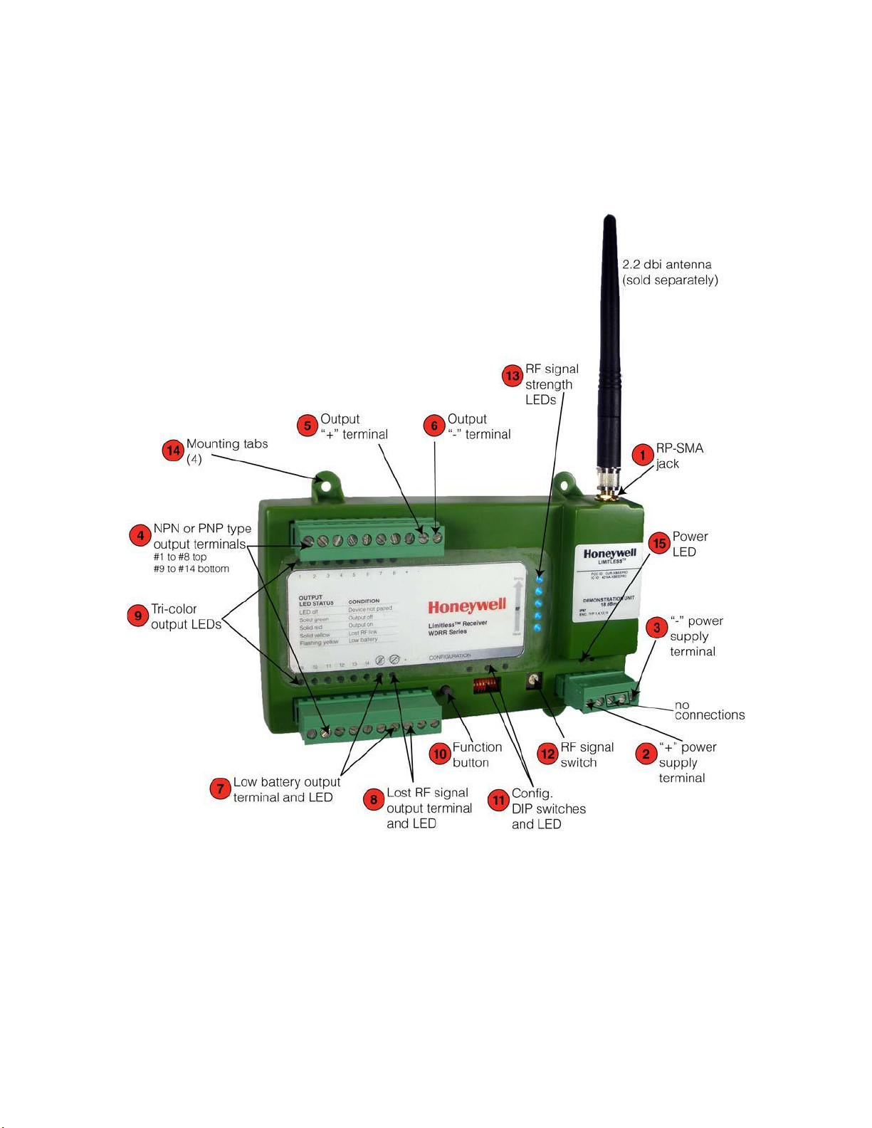
This WDRR (Wireless DIN-Rail Receiver) Series quick start installation guide provides basic installation instructions
and product functionality for the Limitless™ WDRR Series when used in conjunction with up to fourteen (14)
Limitless™ inputs. Figure 1 (see below) contains labels of the features and descriptions of the WDRR DIN-Rail
Receiver where the function, operation, etc. of each will be provided throughout this document.
Figure 1 – Limitless™ WDRR Din-Rail Receiver with location call-outs
Honeywell Sensing and Control
Page 3
Limitless™ WDRR Series
Issue 2,
50063986
3
WARNING
ATTENTION
25B
WARNING
Failure to comply with these instructions could result in death or serious injury.
ATTENTION
NOTICE
NOTICE
1.1 Antenna Connection (refer to Figure 1)
RF EXPOSURE
* To satisfy FCC RF exposure requirements for mobile transmitting devices, a separation distance of 20 cm
[7.87 in] or more should be maintained between the antenna of this device and persons during device
operation. To ensure compliance, operation at closer than this distance is not recommended. The antenna
used for this transmission must not be co-located in conjunction with any other antenna or transmitter.
Failure to comply with these instructions could result in death or serious injury.
A direct mount antenna (either straight or tilt & swivel) can be easily mounted by threading the mating RP-SMA
plug of the antenna to the RP-SMA jack
A remote mount antenna requires the use of an extension cable to allow the antenna to be mounted in a different
location than the WDRR location. The extension cable will need to have one end with a RP-SMA plug connector
which will mate with the WDRR RP-SMA jack
Only Honeywell antennas types should be used. The antenna gain when using the WDRR should
meet the Country Communication Agency requirements for the specific country the WDRR is being
used in. Contact Honeywell for further information.
on the WDRR. Tighten the connection until finger tight.
under the same mounting procedure as the direct mount antenna.
1.2
Electrical Connections (refer to Figure 1)
RISK OF ELECTRICAL SHOCK
* Potential shock hazard where HAZARDOUS LIVE voltages greater than 30 Vrms, 42.4 Vpeak, or 60 Vdc
may be accessible.
Do not run the electrical wires in parallel and close proximity to the antenna or antenna cable.
Power supply connections: The Limitless™ WDRR Series has two cage clamp screw terminals on the bottom
right of the housing. A regulated voltage supply of 10 Vdc to 28 Vdc needs to be connected to the terminals
identified as “+”
number, WDRRPWRASM, will need to be used and electrical connections made as shown in Figure 2.
The measured voltage across the output “-” terminal and the output “+” terminal is
nominally 1.5 Vdc less than the voltage supplied.
ANATEL requires the use of Honeywell part number WDRRPWRASM.
and “-” power supply terminals. Notice: if the product is being used in Brazil, Honeywell part
Honeywell Sensing and Control
Page 4

Limitless™ WDRR Series
Issue 2,
50063986
4
CAUTION
Do not apply direct power (supply voltage “+” or “-”) to the “-” terminal or “+” terminal or any
Figure 2. Limitless™ WDRR Din-Rail Receiver with WDRRPWRASM connected
Brown wire connects to positive power supply terminal. Blue wire connects to negative power supply terminal.
NPN or PNP output connections: The WDRR Series Receiver is supplied with fourteen (14) configurable
NPN/PNP type outputs intended to be used with a customer provided PLC. A specific output will change when one
or more of the Limitless™ input(s) changes. The customer has the option of connecting the outputs for use as:
NPN- type current sinking or totem pole (current sinking); PNP-type current sourcing or totem pole (current
sourcing). See Section 1.3 for proper settings of the DIP switches. The connections to the customer’s PLC would
be as follows for each:
NPN-type: Current Sinking or Totem Pole (current sinking) output connecting to a PLC sourcing input
- Connect NPN-type terminal
- Connect Output “+” terminal
- No connection to Output “-” terminal
PNP-type: Current Sourcing or Totem Pole (current sourcing) output connecting to a PLC sinking input
- Connect PNP-type terminal
- Connect Output “-” terminal
- No connection to Output “+” terminal
of the NPN/PNP type output terminals as damage could occur to the WDRR electronics.
to PLC sourcing input
to PLC common
to PLC sinking input
to PLC common
Honeywell Sensing and Control
Page 5

Limitless™ WDRR Series
Issue 2,
50063986
5
CAUTION
Do not apply direct power (supply voltage “+” or “-”) to the “-” terminal or “+” terminal or any
of the NPN/PNP type output terminals as damage could occur to the WDRR electronics.
CAUTION
Do not apply direct power (supply voltage “+” or “-”) to the “-” terminal or “+” terminal or any of
The Limitless™ WDRR Series is supplied with one configurable NPN/PNP type “low battery” output intended to be
used with a customer provided PLC. The output changes state when one or more of the Limitless™ inputs has a
low battery. The customer has the option of connecting the outputs for use as: NPN type-current sinking or totem
pole (current sinking); PNP type-current sourcing or totem pole (current sourcing). See Section 1.3 for proper
settings of the DIP switches. The connections to the customer’s PLC would be as follows for each:
NPN type-Current Sinking or Totem Pole (current sinking) output connecting to a PLC sourcing input:
- Low battery output terminal
- Connect Output “+” terminal
- No connection to Output “-” terminal
PNP type-Current Sourcing or Totem Pole (current sourcing) output connecting to a PLC sinking input:
- Low battery output terminal
- Connect Output “-” terminal
- No connection to Output “+” terminal
Lost RF Link output connection: The Limitless™ WDRR Series is supplied with one configurable NPN/PNP type
“Lost RF Link” output intended to be used with a customer provided PLC. The output changes state when one or
more of the Limitless™ inputs has lost RF Link with the WDRR. The customer has the option of connecting the
outputs for use as: NPN type-current sinking or totem pole (current sinking); PNP type-current sourcing or totem
pole (current sourcing). See Section 1.3 for proper settings of the DIP switches. The connections to the customer’s
PLC would be as follows for each:
NPN type-Current Sinking or Totem Pole (current sinking) output connecting to a PLC sourcing input:
- Lost RF link output terminal
- Connect Output “+” terminal
- No connection to Output “-” terminal
PNP type-Current Sourcing or Totem Pole (current sourcing) output connecting to a PLC sinking input:
- Low battery output terminal
-Connect Output “-” terminal
- No connection to Output “+” terminal
to PLC sourcing input
to PLC common
to PLC sinking input
to PLC common
to PLC sourcing input
to PLC common
to PLC sinking input
to PLC common
the NPN/PNP type output terminals as damage could occur to the WDRR electronics.
Honeywell Sensing and Control
Page 6

Limitless™ WDRR Series
Issue 2,
50063986
6
OUTPUT TYPE
DIP SW 1 LOGIC
DIP SW 2 LOGIC
NPN-type: Current sinking open collector
OFF
OFF
PNP-type: Current sourcing open collector
ON
OFF
NPN-type: Totem pole (current sinking)
OFF
ON
PNP-type: Totem pole (current sourcing)
ON
ON
Switch position
NPN/PNP Input/Output # - RF Link strength displayed
0
None-Normal operation
1
1
2
2
3
3
4 4 5
5
6
6
7
7
8
8
9 9 A
10 B 11 C 12
D
13
E
14
F
None-LED test mode
1.3 Configuration DIP switches
The NPN/PNP-type outputs , NPN/PNP-type “low battery” output , and NPN/PNP-type “Lost RF Link” output
may be connected for use as: NPN-type current sinking or totem pole; PNP-type current sourcing or totem pole.
The configuration DIP switches
PLC as follows:
Note: DIP switches 3 thru 8 are not used; factory default for both DIP switches is OFF.
1.4 RF Link switch
The RF Link switch allows users to select between the 14 different Limitless™ outputs to view the RF link strength
of a specific Limitless™ input. The five (5) blue LEDs will then indicate the RF link strength of the Limitless™ input
and corresponding output that is chosen (reference section 1.5.6). The following chart identifies the switch position
that is related to each Limitless™ input/output.
identified as “1” and “2” on the DIP switch housing can be set to interface with a
Note: Factory default switch position is zero
1.5 Functional Indicator
The Limitless™ WDRR Series has several LEDs to indicate various states, functions, actions, etc. The LEDs
functions will be described in this section and their indication will depend on the position of the RF Link switch
1.5.1 Power LED
Refer to Figure 1. One green LED turns on to indicate power is applied to the WDRR receiver. This occurs when
the electrical power is supplied to the “+”
Honeywell Sensing and Control
and “-” power supply terminals.
.
Page 7

Limitless™ WDRR Series
50063986
7
Output on & RF signal strength LEDs indicated for chosen output
Sequence each LED color
LED test mode
Solid green
Acceptable voltage(s)
Solid red
Low voltage(s)
Sequence each LED color
LED test mode
Condition
Solid green
Acceptable RF link(s)
Solid red
Lost RF link(s)
Sequence each LED color
LED test mode
1.5.2 Tri-color Output LEDs:
RF Link switch position “0”
Output LED status
LED off No device paired to output
Solid green Output off (set-up mode allows indication to be reversed)
Solid red Output on (set-up mode allows indication to be reversed)
Solid yellow Lost RF link
Flashing yellow Low battery
RF Link switch position 1-9, A-E
Output LED status
LED off No device paired to output
Flashing green
Flashing red
Solid yellow Lost RF link
Flashing yellow Low battery
RF Link switch position F
Condition
Condition (RF Signal switch position 1-9, A-E)
Output off & RF signal strength LEDs
indicated for chosen output
Issue 2,
1.5.3 Low Battery output LED
RF Llink switch position 0-9, A-E
Low battery LED status Condition
RF Signal switch position F
1.5.4 Lost RF Link output LED
RF Link switch position 0-9, A-E
Lost RF Signal LED status
RF Link switch position F
Honeywell Sensing and Control
Page 8

Limitless™ WDRR Series
Issue 2,
50063986
8
1.5.5 Function Button and Configuration LEDs Operation
The Function button allows the Limitless™ WDRR Receiver to enter many different configuration modes such as
Set-up, Pairing, Purge, etc. while the configuration LEDs will indicate the different modes as well as different states.
This Quick Start Guide (QSG) will only show the use of the function button and configuration LEDs when in the
Pairing Mode (see Section 1.7) and Start-up or Restart Sequence (see Section 1.6)
1.5.6 RF Link Strength LEDs
The five (5) blue LEDs indicate the RF Link Strength of the Limitless™ input when communicating (i.e.
Limitless™ input change of state/actuation) with the WDRR Receiver. One (1) blue LED on indicates a weak RF
link and the increased number of blue LEDs on indicates a stronger RF link.
1.6 Start-up or Re-start Sequence
Apply power to the “+” and “-” power supply terminals and the following describe how the WDRR
Configuration LEDs
Zero switches paired to the WDRR: The Configuration LEDs
performs a channel scan. Afterwards, all Configuration LEDs
illuminate. This indicates power is being supplied to the Limitless™ WDRR, and the unit is ready to use.
will indicate that the Limitless™ WDRR is ready for use:
will illuminate for a few seconds while the WDRR
will turn off and only the green power LED will
One or more switches paired (per Section 1.7) to the WDRR: The Configuration LEDs
few seconds while the WDRR performs a channel scan. The WDRR Receiver will then enter a System Check Mode
for up to two minutes. The red, yellow, and green Configuration LEDs
check is successfully completed. At which time, all Configuration LEDs
will illuminate indicating power is being supplied to the WDRR. The Limitless™ WDRR is ready to use, and will also
display the status of tri-color output LEDs
assuming the RF Link switch
is in position “0”.
, low battery output LED , and lost RF signal output LED
illuminate sequentially until the system
will turn off, and the green power LED
will illuminate for a
1.7 Pairing Mode (Factory Default: No Limitless™ Inputs Paired)
Pairing is required to initiate and establish an RF communication link between a single WDRR and a single
Limitless™ input. The Limitless™ input example used in this Quick Start Guide (QSG) will be the Limitless™
WGLA switch.
The Limitless™ switch is shipped from the factory with two identification labels
recommended to be completed and applied to the Limitless™ switch housing during the pairing mode. As there are
up to 14 Limitless™ switches that can be paired to a single WDRR, these labels will be used to identify the
Limitless™ switch in the sequence of #1 to #14. The initial Limitless™ switch paired to the WDRR receiver will be
Sequence #1 (corresponding to output #1); the second Limitless™ switch paired will be Sequence #2
(corresponding to output #2) and so on.
The battery will need to be activated in the Limitless™ switch and proper power applied to the WDRR Series
Receiver before proceeding with this pairing procedure. Once the pairing is completed, the Limitless™ switch
selected will only communicate with the WDRR Receiver it was paired to and no other device.
(see Figure 5) that are
Honeywell Sensing and Control
Page 9

Limitless™ WDRR Series
Issue 2,
50063986
9
Step
Action
performed.
Limitless™ switch and locate the function button (see Figure 4) to be used in Step 4.
release the function button immediately as it has entered the pairing mode.
also turn on.
the Tricolor Output LED (see Figure 1) should turn on to indicate the proper output status.
housing in desired locations (See Figure 6).
1 Completely read this procedure before starting in order to understand the timing of events that need to be
2 Limitless™ switch: Remove (if required) the two screws on the housing cover (See Figure 3) of the
3 WDRR: Press the Function button on WDRR (See Figure 4) for more than four seconds and less than
eight seconds at which time the green and yellow LEDs
4 Limitless™ switch: Within a 30 second interval of Step 3, depress the Limitless™ switch function button
(See Figure 5) and hold depressed for more than one second and less than 12 seconds at which time the
orange
second. The orange
does not succeed, the orange
5 WDRR Receiver: Successful pairing will be indicated by the green and amber LEDs (see Figure 4)
ceasing to flash and remaining on for a few seconds before turning off. The specific Tricolor Output LED will
6 To confirm proper pairing between the Limitless™ switch and WDRR, actuate the Limitless™ switch, and
7 Record the Limitless™ switch Sequence # on identification labels and apply to the Limitless™ switch
8 Repeat Steps 2-7 to add additional Limitless™ switch. Up to 14 Limitless™ switches can be paired to a
single WDRR.
LED turns on (see Figure 5). While in pairing mode, the orange led will flash on for 100 ms every
LED flashes three times 100 ms on, 100 ms off when pairing succeeds. If pairing
LED will turn off and user will need to repeat steps starting with Step 3.
(see Figure 4) will be flashing which indicates to
Honeywell Sensing and Control
Page 10

Limitless™ WDRR Series
50063986
10
Figure 3. Limitless™ Switch Housing
Issue 2,
Figure 5. Limitless™ Switch with Function Button
Depressed
Figure 4. Limitless™ Switch Housing
NOTE: Use a blunt object, such as a paper clip or
tooth pick to actuate the function switch
Figure 6. Limitless™ Switch Label Placement
-
.
Honeywell Sensing and Control
Page 11

Limitless™ WDRR Series
Issue 2,
50063986
11
1.8 WDRR Mounting
The WDRR is intended to be mounted to a DIN-Rail or mounted via the four (4) mounting tabs.
DIN Rail mounting: The WDRR Receiver is supplied with two snap in DIN-Rail tabs that will need to be inserted
into the back of the WDRR housing as shown below.
Figure 7. Limitless™ WDRR Mounting Clips
Tab mounting: The WDRR has four tabs that are intended to allow mounting with a #6 style screw. As there are
many types of screw fasteners, care should be taken to not overtighten the fastener and cause the mounting
tab/housing to crack or fracture. Also, ensure that the housing is being mounted on a flat surface.
Figure 8. Limitless™ WDRR Mounting Tabs
Honeywell Sensing and Control
Page 12

Limitless™ WDRR Series
Issue 2,
50063986
12
Figure 9. Limitless™ WGLA
Figure 10. Limitless™ WDRR
1.9 Antenna Adjustment
The antenna of the Limitless™ WDRR and WGLA should be oriented so that they are parallel with each other. This
will in most cases allow the longest range and highest RF link strength. The least RF link strength is normally in a
direction in-line with the top of the antenna, so it is best to avoid having the antennas pointed directly toward each
other, or directly away from each other. An acceptable RF link strength is also indicated on the WDRR with five (5)
blue LEDs
.
WARNING
RF EXPOSURE
• To satisfy FCC RF exposure requirements for mobile transmitting devices, a separation distance of 20 cm [7.87 in] or more
should be maintained between the antenna of this device and persons during device operation. To ensure compliance,
operations at closer than this distance is not recommended. The antenna used for this transmitter must not be co-located in
conjunction with any other antenna or transmitter.
Failure to comply with these instructions could result in death or serious injury.
Honeywell Sensing and Control
Page 13

Limitless™ WDRR Series
50063986
www.honeywell.com
Copyright © 2012 Honeywell International Inc. All rights reserved.
WARRANTY/REMEDY
Honeywell warrants goods of its manufacture as being free
of defective materials and faulty workmanship. Honeywell’s
standard product warranty applies unless agreed to
otherwise by Honeywell in writing; please refer to your
order acknowledgement or consult your local sales office
for specific warranty details. If warranted goods are
returned to Honeywell during the period of coverage,
Honeywell will repair or replace, at its option, without
charge those items it finds defective. The foregoing is
buyer’s sole remedy and is in lieu of all other
warranties, expressed or implied, including those of
merchantability and fitness for a particular purpose. In
no event shall Honeywell be liable for consequential,
special, or indirect damages.
While we provide application assistance personally,
through our literature and the Honeywell web site, it is up to
the customer to determine the suitability of the product in
the application.
Specifications may change without notice. The information
we supply is believed to be accurate and reliable as of this
printing. However, we assume no responsibility for its use.
Issue 2,
SALES AND SERVICE
Honeywell serves its customers through a worldwide
network of sales offices, representatives and distributors.
For application assistance, current specifications, pricing or
name of the nearest Authorized Distributor, contact your
local sales office or:
E-mail: info.sc@honeywell.com
Internet: www.honeywell.com/sensing
Phone and Fax:
Asia Pacific +65 6355-2828
+65 6445-3033 Fax
Europe +44 (0) 1698 481481
+44 (0) 1698 481676 Fax
Latin America +1-305-805-8188
+1-305-883-8257 Fax
USA/Canada +1-800-537-6945
+1-815-235-6847
+1-815-235-6545 Fax
Sensing and Control
Honeywell
1985 Douglas Drive North
Golden Valley, MN 55422
50063986-002 IL50 GLO Printed in USA
April 2012
 Loading...