

Page 1

THE L4080 AND L8080 ARE IMMERSION
TYPE CONTROLLERS FOR HYDRONIC
HEATING SYSTEMS THAT TURN OFF THE
BURNER WHENEVER THE BOILER WATER
TEMPERATURE RISESTOTHESET POINT.
0 L4080 High Limit Aquastat Controller has
adjustable set point.
Cl L4080 models available for use with
immersion wells or for direct immersion if
faster response is needed.
0 A factory-set stop is available on L4080 to
prevent setting the control at too high a
temperature.
-
0
Cl L4080 models available with second limit
switch to shut off all gas to the burner.
III L8080 EC0 gas shutoff has fixed set point.
0 Liquid fill in sensing element expands as
the boiler temperature rises.
Cl At the set point temperature, a diaphragmactuated snap switch breaks the power
supply to the burner primary control.
SM.
REV. 4-66m
Form Number 60-2101-2
@Honeywell Inc. 1966
Page 2

I
SPEClFICATIONS
THE SPECIFICATIONS GIVEN IN THIS PUBLICATION DO NOT INCLUDE NORMAL MANUFACTURING TOLERANCES.
THEREFORE, THIS UNIT MAY NOT MATCH THE LISTED SPECIFICATIONS EXACTLY. ALSO, THIS PRODUCT IS TESTED AND
CALIBRATED UNDER CLOSELY CONTROLLED CONDITIONS, AND SOME MINOR DIFFERENCES IN PERFORMANCE CAN BE
EXPECTED IF THOSE CONDITIONS ARE CHANGED.
CASE
MODEL
NUMBER
-~
L408OB
L4080D
L408OF
L4080G
DESCRIPTION
High Limit
Aquastat
Controller
High Limit
Aquastat
Controller
Dual Limit
Aquastat
Controller
Dual Limit
Aquastat
Controller
AND
COVER
Yes
No
Yes
No
IMPORTANT
TABLE I-MODELS
IMMERSION STANDARD
WELL
Yesa
Yesa
Yes
Yes
Yes
RANGE
180Fto240F[82C
to 116 C]; dial
marked in 10 F
[5.6 C] increments.
180Fto240F[82C
to 116 C]: dial
marked in 10 F
[5.6 C] increments.
180 F to 240 F [82 C
to 116 C]; dial
marked in 10 F
[5.6 C] increments;
stop set at 210 F
[98.9 C].
140Fto240F[60C
to 116 C], dial
marked in 10 F
15.6 C] increments;
stop set at 210 F
[98.9 C].
Factory-set, 200 F
[93 C]. Nonadjustable.
OPTIONAL
RANGES
140Fto240F[60Cto116C];
dial marked in 10 F [5.6 C]
increments.
120Fto160F[49Cto71 C];
dial marked WARM-NORMALHOT.
Stop set at 150 F, 200 F, or
220 F [66 C, 93 C, or 104 Cl.
140Fto240F[60Cto116C],
dial marked in 10 F [5.6 C]
increments.
-
-
-
aOn select Band D models, well must be ordered separately. Refer to form 68-0040, “Wells and Fittings for Temperature
Controllers,” to order well, if necessary
V?WiRING INFORMATlON
WHEN PURCHASING REPLACEMENT AND MODERNIZATION PRODUCTS FROM YOUR TRADELINE
WHOLESALER OR YOUR DISTRIBUTOR, REFER TO THE TRADELINE CATALOG OR PRICE SHEETS FOR
COMPLETE ORDERING NUMBER, OR SPECIFY-
1. Order number.
2. Control range (LSOSO only).
IF YOU HAVE ADDITIONAL QUESTIONS, NEED FURTHER INFORMATION, OR WOULD LIKE TO COMMENT ON OUR
PRODUCTS OR SERVICES, PLEASE WRITE OR PHONE:
1. YOUR LOCAL HONEYWELL RESIDENTIAL SALES OFFICE (CHECK WHITE PAGES OF YOUR PHONE DIRECTORY).
2. RESIDENTIAL DIVISION CUSTOMER SERVICE
HONEYWELL INC., 1885 DOUGLAS DRIVE NORTH
MINNEAPOLIS, MINNESOTA 55422-4386 (612) 542-7500
IN CANADA-HONEYWELL CONTROLS LIMITED/HONEYWELL LIMITEE, 740 ELLESMERE ROAD, SCARBOROUGH,
ONTARIO MlP 2V9. INTERNATIONAL SALES AND SERVICE OFFICES IN ALL PRINCIPAL CITIES OF THE WORLD.
3. Dlfferentlal.
4. Optional specifications.
2
Page 3
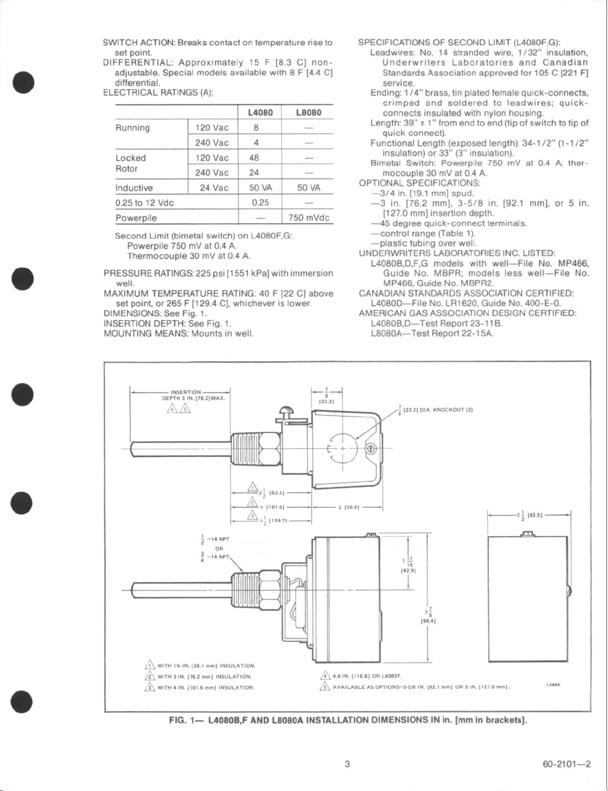
SWITCH ACTION: Breaks contact on temperature rise to
set point.
DIFFERENTIAL: Approximately 15 F [8.3 C] non-
adjustable. Special models available with 8 F (4.4 C]
differential.
ELECTRICAL RATINGS (A):
I L4080 I L8080
Inductive
0.25 to 12 Vdc
Powerpile
Second Limit (bimetal switch) on L4080F,G:
Powerpile 750 mV at 0.4 A.
Thermocouple 30 mV at 0.4 A.
PRESSURE RATINGS: 225 psi [1551 kPa] with immersion
well.
MAXIMUM TEMPERATURE RATING: 40 F [22 C] above
set point, or 265 F [129.4 C], whichever is lower.
DIMENSIONS: See Fig. 1.
INSERTION DEPTH: See Fig. 1.
MOUNTING MEANS: Mounts in well.
I 24Vac i 50~~ i
1 0.25 i -
-
50 VA
750 mVdc
SPECIFICATIONS OF SECOND LIMIT (L4080F.G):
Leadwires: No. 14 stranded wire, l/32” insulation,
Underwriters Laboratories and Canadian
Standards Association approved for 105 C [221 F]
service.
Ending: l/4” brass, tin plated female quick-connects,
crimped and soldered to leadwires; quickconnects insulated with nylon housing.
Length: 39” f 1” from end to end (tip of switch to tip of
quick connect).
Functional Length (exposed length): 34-l 12” (l-l /2”
insulation) or 33” (3” insulation).
Bimetal Switch: Powerpile 750 mV at 0.4 A; ther-
mocouple 30 mV at 0.4 A.
OPTIONAL SPECIFICATIONS:
-3/4 in. [19.1 mm] spud.
-3 in. [76.2 mm], 3-5/E in. [92.1 mm], or 5 in.
[127.0 mm] insertion depth.
-45 degree quick-connect terminals.
-control range (Table 1).
-plastic tubing over well.
UNDERWRITERS LABORATORIES INC. LISTED:
L4080B,D,F,G models with well-File No. MP466.
Guide No. MBPR; models less well-File No.
MP466, Guide No. MBPR2.
CANADIAN STANDARDS ASSOCIATION CERTIFIED:
L4080D-File No. LR1620, Guide No. 400-E-0.
AMERICAN GAS ASSOCIATION DESIGN CERTIFIED:
L408OB,D-Test Report 23-l 1 B.
L8080A-Test Report 22-l 5A.
FIG. l- L408OB,F AND L8080A INSTALLATION DIMENSIONS IN in. [mm in brackets].
I
3
60-2101-2
Page 4

l-
141 3, ,794,
,\ 16 IN ,116 6, ON L4066G.
2 AYAILABLE AS OPTIONS-_).5/6 IN p2.1 mm, OR 5 IN ,127.o mm,.
A
FIG. 2-L4080D,G INSTALLATION DIMENSIONS IN in. [mm in brackets].
W-y
MVSTALLATION
t-’
WHEN INSTALLING THIS PRODUCT. . .
1. Read these tnstructions carefully. Failure to follow
them could damage the product or cause a hazardous
condition.
2. Check the ratings given in the instructions and on
the product to make sure the product is suitable for your
application.
3. Installer must be a trained, experienced service
technician.
4. After installation is complete, check out product
operation as provided in these instructions.
ND MOUNTING
.,
,I
The L4080 or L8080 is mounted in a tapping which is
usually provided by the boiler manufacturer, at a location
where it will sense average water temperatures.
1. Disconnect power supply and drain boiler.
2. If no tapping is provided, prepare one at a location
that will permit boiler water of average temperature to
circulate freely about the element.
3. L4080A-insert in boiler tapping. Using wrench on
hex nut only, tighten securely. Do not use the L4080 as a
lever to tighten the connection.
4. L4080B,D and L8080A-install immersion well in
boiler tapping, tighten securely. Insert sensing element in
well, tighten setscrew.
5. Refill boiler and check for water leaks. If well needs
tightening, use wrench on hex nut only.
SETTINGS (L4080 only)
Because heating systems differ, follow the burner
manufacturer’s recommendations when selecting the
proper Aquastat controller setting.
Turn the notched wheel until the desired high limit
setting coincides with the arrowhead indicator at the side
of the switch.
On the L408OF and G, the second high limit is not
adjustable.
WIRING
Disconnect power supply before connecting wiring to
prevent electrical shock or equipment damage.
All wiring must comply with applicable codes and
ordinances.
Wire the L4080 in the control circuit. Wire the L8080 in
series with the gas control power unit. Figs. 3-10 show
typical wiring diagrams.
4
Page 5

POWERPILE
THERMOSTAT
I
L----u**Ar---!
POWER UNIT COIL
(r**A*)OPERATOR COIL
FIG. 3-L4080B,D; L8080A TYPICAL WIRING HOOKUP
FOR 3 TERMINAL POWERPILE SYSTEMS.
1 BROKEN LINES REPRESENT INTERNAL WIRING.
2 PILOTSTAT POWER “NIT COIL.
3 VALVE OPERATOR COIL.
n
IO,,M
I
FIG. 4-L4080B,D; L808OA TYPICAL WIRING HOOKUI
FOR 4 TERMINAL POWERPILE SYSTEMS.
LINE VOLTAGE
THERMOSTAT
OR CONTROLLER
LINE VOLTAGE
OPERATOR
3
1 POWER SUPPLY. PROVIDE DISCONNECT MEANS AND OVERLOAD PRO.
n
TECTlON AS REQUIRED
FIG. 5-L4080B,D: L8080A TYPICAL WIRING HOOKUP
FOR 24 V SYSTEMS.
1 POWER SVPPLY. PROVIDE DISCONNECT MEANS AND OVERLOAO
n
PROTECTtON AS REOVIRED.
FIG. 844080B,D; L8080A TYPICAL WIRING HOOKUP
FOR LINE VOLTAGE SYSTEM.
5
60-2101-2
Page 6

I
L--7****r---?
POWER “NIT COIL
(****A) OPERATOR COIL
‘IG. 7-L4080F,G TYPICAL WIRING HOOKUP FOR 4-
TERMINAL POWERPILE CONTROL SYSTEMS.
FIG. 844080F,G TYPICAL WIRING HOOKUP FOR 3-
TERMINAL POWERPILE CONTROL SYSTEMS.
I
(SUGGESTED AS FIELD REPLACEMENT ONLY;
FOR NEW SYSTEMS, USE 4-TERMINAL
MODEL.)
1 POWER SVPPLY. PROVIDE DISCONNECT MEANS ANOO”ERLOAD PR
n
TECTION AS REOVIREO.
.._^
FIG. 9-L408OF,G TYPICAL WIRING HOOKUP FOR 24 V
SYSTEMS.
FIG. lO-L4080F,G TYPICAL WIRING HOOKUP FOR
LINE VOLTAGE SYSTEMS.
6
Page 7

OPERATidN
When the water temperature rises to the L4080 or
LB080 set point, the liquid fill in the sensing unit expands,
actuating a diaphram which interrupts the power supply
to the burner primary control (L4080) or the Pilotstat
power unit (L8080).
When the L4080 interrupts powerto the burner primary
control, the system automatically recycles when the
water cools and the L4080 switch closes.
CHECKOUT
Do not operate burner by lumpenng gas valve
terminals; this bypasses the temperature and limit
1
Turn on the power supply. Start the heating system
according to instructions supplied with the burner con-
On the L408OF and G, when the second limit is
reached, the Pilotstat power unit circuit opens, shutting
off all gas to the heater. Manual reset of the system is
required to restart
When the La080 interrupts powerto the Pilotstat power
unit, the water must cool to approximately 120 F [49 C]
and the gas control’s power unit must be reset before the
system will operate.
trol or main gas valve. Turn the L4080 to the low end of its
range, and be sure the control shuts off the burner when
the set point is reached. Set the L4080 High Limit Aquastat
Controller to the manufacturer’s recommended setting
before leaving job.
The L8080A is factory-set and nonadjustable. Check
that the power unit drops out and that gas flow is
interrupted when the L808O’s set point is reached (200 F
[93 C]. Reset power unit before leaving job.
lwwywoll Inc.
1666 Douglas Dnve N.
Golden Valley, MN 55422-4366
rnremationer tires OmCes in all principal Cities of the world. Manufachrrlng in Australia,
France, Germany. Japan, Mexico. Netherlands, Spain, Taiwan, United Kingdom, U.S.A.
I
Canada, Finland,
PRINTED IN USA
 Loading...