

Page 1
Put UPC Code Here
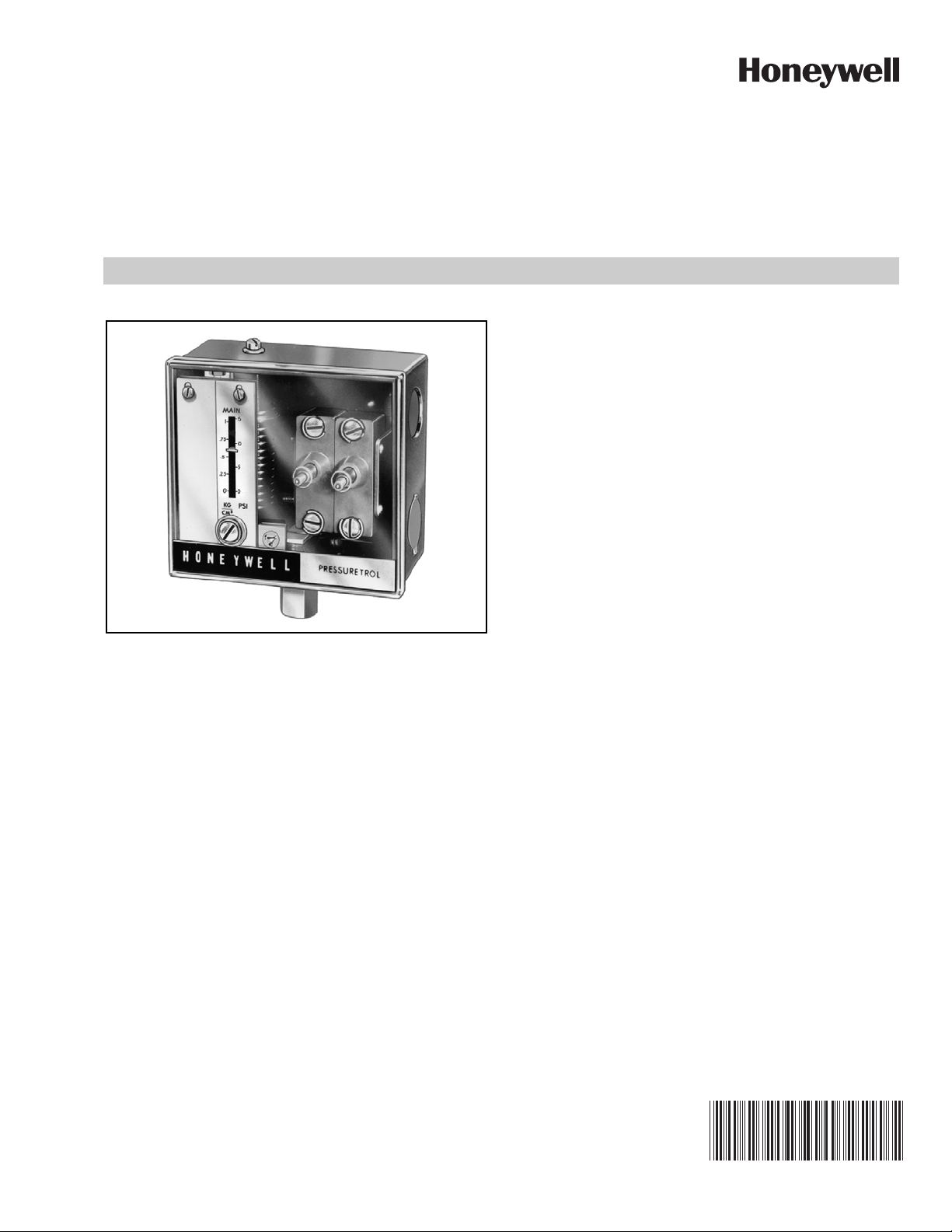
L4079A,B,W
PressureTrol® Limit Control
FEATURES
• L4079A has two ganged spst switches; breaks two
circuits (may be both sides of the power supply)
simultaneously.
• L4079B has one spst switch.
• L4079W is the same as L4079B but has seals for oil
applications.
®
• MICRO SWITCH
through transparent cover.
• Switches open automatically but must be reset
manually.
• Trip-free reset mechanisms do not permit the limiting
role of the PressureTrol
jamming the reset lever.
• Control does not need leveling.
• The L4079 is unaffected by moderate vibration.
snap-acting switches are visible
®
Control to be defeated by
PRODUCT DATA
APPLICATION
The L4079A,B, and W PressureTrol® Limit Controls are high
pressure limit switches that break electrical circuits when
pressure rises to a preset value.
The L4079A and B can be used with steam, air,
noncombustible gases, and fluids noncorrosive to the sensing
element.
L4079W is for use on oil burner systems.
Contents
Application .......................................................................... 1
Features ............................................................................. 1
Specifications ..................................................................... 2
Installation .......................................................................... 3
Wiring ................................................................................. 3
Checkout ............................................................................. 4
60-2156—05
Page 2
L4079A,B,W PRESSURETROL® LIMIT CONTROL
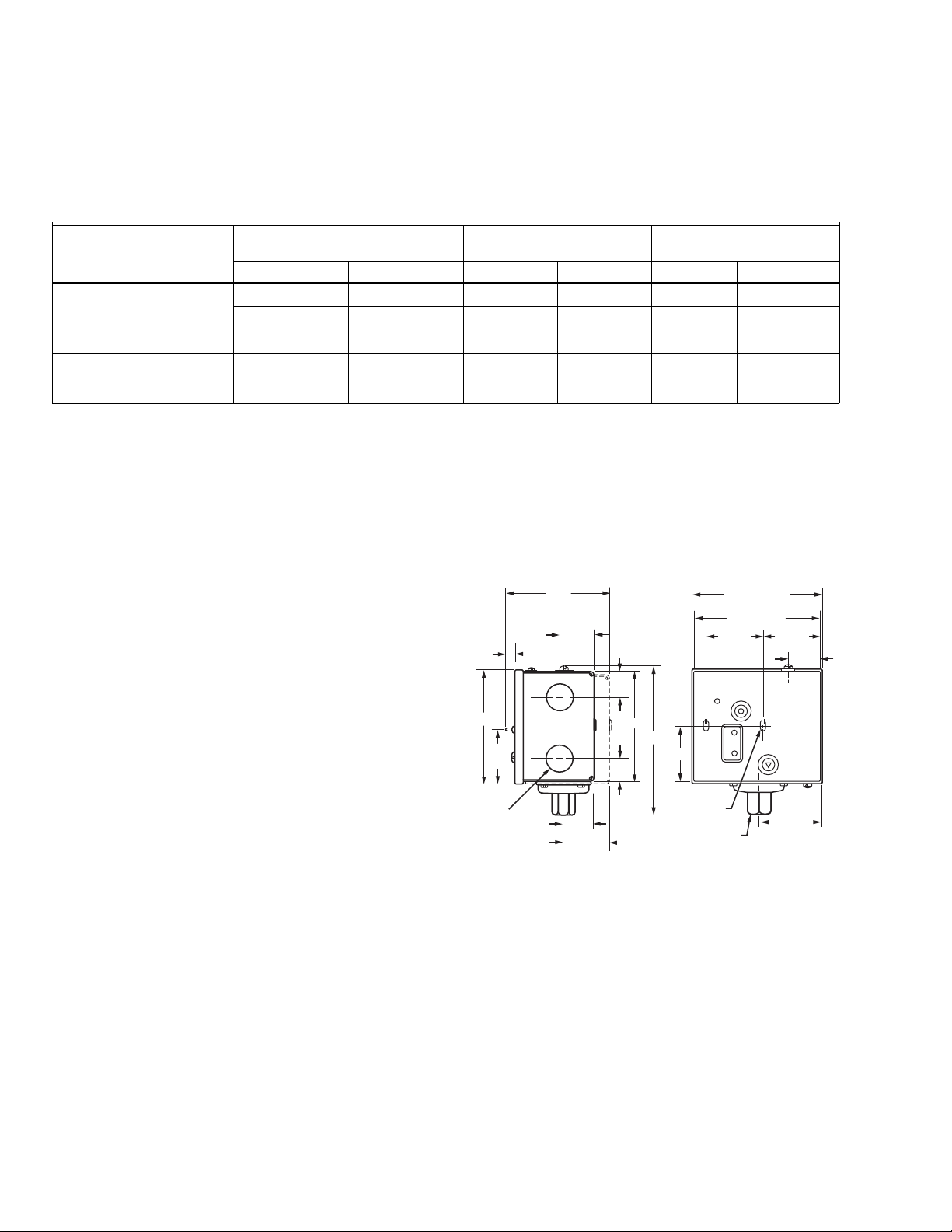
3-7/8
1/4
(2-15 PSI ONLY)
KNOCKOUT
FOR 1/2 INCH
CONDUIT (2)
1/4
4-15/16
KNOCKOUT
(2) FOR NO.
10 SCREW
1/4 - 18 NPT
1-
1/16
M22435
2-1/8
1-
13/16
1-
13/16
13/16
13/16
3-1/2
1-1/2
3/16
1-13/16
4-1/2 (COVER)
4-3/8 (CASE)
1-15/16
1-15/16
SPECIFICATIONS
Models: See Table 1.
Pressure Ratings: See Table 1.
Table 1. Pressure Ratings.
Range
Model Number
L4079A
a
and L4079B
b
psi kPa psi kPa psi kPa
2 to 15 15 to 100 25 170
5 to 50 35 to 350 85 590 10
10 to 150 70 to 1035 225 1550 30
L4079B1066
L4079W1000
a
Ratings apply to each of two separate circuits.
b
One circuit only.
b
b
20 to 300 140 to 2070 350 2410 60
10 to 150 70 to 1035 225 1550 30
Switching Action:
L4079A—Snap-switch. Breaks two circuits automatically on
pressure rise. Each circuit must be manually reset.
L4079B,W—Snap-switch. Breaks one circuit automatically on
pressure rise. Circuit must be manually reset.
Adjustment means: External adjustment screw. Scale is
calibrated in psi and kPa.
Electrical Ratings:
120 Vac: 9.8 Amps for full load; 58.8 Amps for locked rotor
240 Vac: 4.9 Amps for full load; 29.4 Amps for locked rotor
Maximum Diaphragm
Pressure Differentials
3 20.7
68.9
206.8
413.7
206.8
Accessories:
50024585-001 Brass Steam Trap.
14026 Steel Steam Trap.
33312B Knurled adjustment knob.
Dimensions: See Fig. 1.
Maximum Ambient Temperature: 150°F (66°C).
Mounting Means:
Pipe fitting—1/4-18 NPT. Connection on diaphragm assembly.
These devices may be either boiler mounted directly to a
boiler fitting, or may be surface mounted, such as on a wall,
by using the knockouts in the case.
Approvals:
Underwriters Laboratories Inc. (UL) Listed: File No. MP466,
Guide No. MBPR.
Canadian Standards Association (CSA): File No. LR95329,
Certificate No. 1720340
Fig. 1. L4079A,B,W PressureTrol
®
Limit Control
dimensions in inches.
ORDERING INFORMATION
When purchasing replacement and modernization products from your TRADELINE® wholesaler or distributor, refer to the
TRADELINE® Catalog or price sheets for complete ordering number. If you have additional questions, need further information,
or would like to comment on our products or services, please write or phone:
1. Your local Honeywell Environmental and Combustion Controls Sales Office (check white pages of your phone directory).
2. Honeywell Customer Care
1885 Douglas Drive North
Minneapolis, Minnesota 55422-4386
3. http://customer.honeywell.com or http://customer.honeywell.ca
International Sales and Service Offices in all principal cities of the world. Manufacturing in Belgium, Canada, China, Czech
Republic, Germany, Hungary, Italy, Mexico, Netherlands, United Kingdom, and United States.
60-2156—05 2
Page 3

INSTALLATION
WARNING
M22436
LINE VOLTAGE
THERMOSTAT
L4079A
L4079B, W
L1 (HOT)
L2
POWER
SUPPLY
TO
THERMOSTAT
(HOT)
TO POWER
SUPPLY
MOTOR
TO
MOTOR
RISE
RISE
RISE
1
PROVIDE DISCONNECT MEANS AND OVERLOAD
P
ROTE
CTION
AS REQUIRED.
1
M22437
PRESSURE
ADJUSTING
SCREW
PRESSURE
SETTING
INDICATOR
SCALEPLATE
MANUAL
RESET
BUTTONS
When Installing This Product…
1. Read these instructions carefully. Failure to follow them
could damage the product or cause a hazardous
condition.
2. Check on the ratings given in the instructions and
marked on the product to make sure the product is
suitable for your application.
3. Installer must be a trained, experienced service
technician.
4. After installation is complete, check out the product operation as provided in these instructions.
Location
PressureTrol® Limit Controllers must be mounted above the
water line in steam boilers. They can be mounted alongside the
pressure gauge, at a remote location, in a fitting provided by
the boiler manufacturer, or in special mountings on
low-water cutoffs.
Mounting
See Fig. 1 for mounting dimensions.
L4079A,B,W PRESSURETROL® LIMIT CONTROL
A steam trap must always be connected between the
PressureTrol
®
unit and the boiler. The steam trap prevents
boiler scale and corrosive vapors from attacking the
diaphragm.
Pressure Gauge Mounting
To mount the limit control beside a pressure gauge, remove the
gauge and install in its place a steam trap with a tee on top.
Mount the PressureTrol® unit and pressure gauge on the side
of the tee by means of nipples and elbows.
Remote Mounting
If excessive vibration seems likely to affect the operation of the
control, it may be located remotely, as long as all piping is
suitable and properly pitched to drain all condensation back to
the boiler.
Boiler Mounting
If it is not convenient to mount the control adjacent to the
pressure gauge, install a steam trap at a location on the boiler
recommended by the boiler manufacturer and screw the unit
directly to the steam trap.
WIRING
All wiring must comply with local codes and ordinances. See
Fig. 2 for internal schematics and wiring.
Electrical Shock Hazard.
Can cause severe injury, death or property damage.
Disconnect the power supply before beginning wiring.
More than one power supply disconnect may be
required.
Fig. 2. Schematics and wiring. L4079A breaks both sides
of power supply; L4079B,W breaks hot side only.
Setting
To set the control, turn the pressure adjusting screw (see Fig.
3) until the pressure setting indicator on the front of the case is
in line with the required control pressure setpoint. The indicator
setting is the point at which the switch breaks contact.
Fig. 3. Controls and indicators on L4079A. L4079B,W is the
same except for having only one reset button.
3 60-2156—05
Page 4

L4079A,B,W PRESSURETROL® LIMIT CONTROL
Manual Resetting
When the circuits have broken automatically, they must be
manually reset. After the pressure returns to setpoint, minus
the differential (shown in Table I), manually reset by firmly
depressing the manual reset button(s) and releasing.
NOTES:
— The circuit is not complete until the reset button is
released.
— The trip-free manual reset mechanism prevents
the limit controller from operating as an automatic
controller (self-resetting) even if the manual reset
button has been tied down.
CHECKOUT
After the control has been installed and wired, test as follows:
1. Note the boiler pressure by checking the boiler pressure
gauge (boiler pressure should be near the middle of the
PressureTrol® pressure scale to perform this test properly).
2. Rotate the PressureTrol
FIg. 3) until the pressure setting indicator on the front of
the case corresponds to the boiler pressure gauge
reading.
NOTE: The limit control should break the control circuit(s)
when the boiler pressure gauge reading equals or
slightly exceeds the PressureTrol
3. If the limit control is operating properly, manually reset it
and adjust the pressure adjusting screw until the pressure setting indicator is in line with the required limit setpoint.
®
pressure adjusting screw (see
®
pressure setting.
Automation and Control Solutions
Honeywell International Inc.
1985 Douglas Drive North
Golden Valley, MN 55422
customer.honeywell.com
® U.S. Registered Trademark
© 2013 Honeywell International Inc.
60-2156—05 KK. Rev. 07-13
Printed in United States
 Loading...