

Page 1
L’
ii
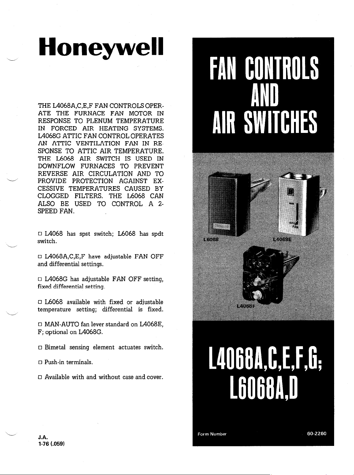
Honeywell
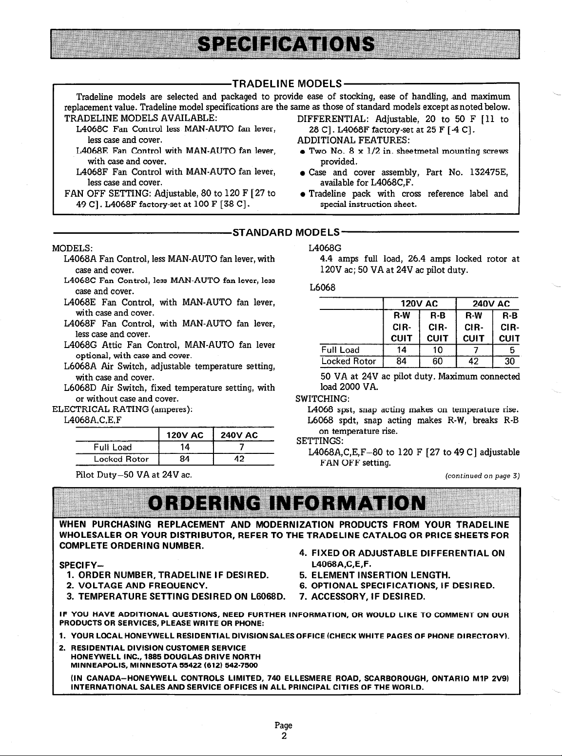
THE L4068A,C,E,F FAN CONTROLS OPERATE THE FURNACE FAN MOTOR IN
RESPONSE TO PLENUM TEMPERATURE
IN FORCED AIR HEATING SYSTEMS.
L4068G ATTIC FAN CONTROL OPERATES
AN ATTIC VENTILATION FAN IN RESPONSE TO ATTIC AIR TEMPERATURE.
THE L6068 AIR SWITCH IS USED IN
DOWNFLOW FURNACES TO PREVENT
REVERSE AIR CIRCULATION AND TO
PROVIDE PROTECTION AGAINST EXCESSIVE TEMPERATURES CAUSED BY
CLOGGED FILTERS. THE L6068 CAN
ALSO BE USED TO CONTROL A 2SPEED FAN.
q L4068 has spst switch; L6068 has spdt
switch.
q L4068A,C,E,F have adjustable FAN OFF
and differential settings.
q L4068G has adjustable FAN OFF setting,
fixed differential setting.
(3 L6068 available with fixed or adjustable
temperature setting; differential is fixed.
q MAN-AUTO fan lever standard on L4068E,
F; optional on L4068G.
q Bimetal sensing element actuates switch.
q Push-in terminals.
q Available with and without case and cover.
L
J.A.
1-76 t.059)
Page 2
TRADELINE MODELS
Tradeline models are selected and packaged to provide ease of stocking, ease of handling, -and maximum
replacement value. Tradeline model specifications are the same as those of standard models except as noted below.
TRADELINE MODELS AVAILABLE:
L4068C Fan Control less MAN-AUTO fan lever,
DIFFERENTIAL: Adjustable, 20 to 50 F [ 11 to
28 C] . L4068F factory-set at 25 F [ -4 C] .
less case and cover. ADDITIONAL FEATURES:
L4068E Fan Control with MAN-AUTO fan lever,
with case and cover.
l Two No. 8 x l/2 in. sheetmetal mounting screws
provided.
L4068F Fan Control with MAN-AUTO fan lever, l Case and cover assembly, Part No. 132475E,
less case and cover.
FAN OFF SETTING: Adjustable, 80 to 120 F [ 27 to
49 C] . L4068F factory-set at 100 F [38 C] .
available for L4068C,F.
l Tradeline pack with cross reference label and
special instruction sheet.
STANDARD MODELS
MODELS:
L4068A Fan Control, less MAN-AUTO fan lever, with
case and cover.
L4068C Fan Control, less MAN-AUTO fan lever, less
case and cover.
L4068G
4.4 amps full load, 26.4 amps locked rotor at
120V ac; 50 VA at 24V ac pilot duty.
L6068
L4068E Fan Control, with MAN-AUTO fan lever,
with case and cover.
L4068F Fan Control, with MAN-AUTO fan lever,
less case and cover.
L4068G Attic Fan Control, MAN-AUTO fan lever
::,-,,
optional, with case and cover.
L6068A Air Switch, adjustable temperature setting,
with case and cover.
L6068D Air Switch, fixed temperature setting, with
or without case and cover.
ELECTRICAL RATING (amperes):
L4068A.C.E.F
240V AC
7
42
Full Load
Locked Rotor
120V AC
14
84
Pilot Duty-50 VA at 24V ac.
50 VA at 24V ac pilot duty. Maximum connected
load 2000 VA.
SWITCHING:
L4068 spst, snap acting makes on temperature rise.
L6068 spdt, snap acting makes R-W, breaks R-B
on temperature rise.
SETTINGS:
L4068A,C,E,F-80 to 120 F [27 to 49 C] adjustable
FAN OFF setting.
(continued on page 3)
COMPLETE ORDERING NUMBER.
I
SPECIFY-
1. ORDER NUMBER, TRADELINE IF DESIRED.
2. VOLTAGE AND FREQUENCY.
3. TEMPERATURE SETTING DESIRED ON L6068D.
IF YOU HAVE ADDITIONAL QUESTIONS, NEED FURTHER INFORMATION, OR WOULD LIKE TO COMMENT ON OUR
PRODUCTS OR SERVICES, PLEASE WRITE OR PHONE:
1. YOUR LOCAL HONEYWELL RESIDENTIAL DIVISION SALES OFFICE (CHECK WHITE PAGES OF PHONE DIRECTORY).
2. RESIDENTIAL DIVISION CUSTOMER SERVICE
HONEYWELL INC., 1885 DOUGLAS DRIVE NORTH
MINNEAPOLIS, MINNESOTA 55422 (812) 542-7500
(IN CANADA-HONEYWELL CONTROLS LIMITED, 740 ELLESMERE ROAD, SCARBOROUGH, ONTARIO MlP 2V9)
INTERNATIONAL SALES AND SERVICE OFFICES IN ALL PRINCIPAL CITIES OF THE WORLD.
4. FIXED OR ADJUSTABLE DIFFERENTIAL ON
L4068A,C,E,F.
5. ELEMENT INSERTION LENGTH.
6. OPTIONAL SPECIFICATIONS, IF DESIRED.
7. ACCESSORY, IF DESIRED.
Page
2
Page 3
L4068G-70 to 110 F [21 to 43 C] adjustable FAN
OFF setting.
L6068A-125 to 165 F [52 to 74 C] adjustable
temperature setting.
L6068D-fixed at 150, 165, or 200 F [66, 74, or
93 C] temperature setting (200 F [93 C] model
less case and cover).
DIFFERENTIAL:
WIRING KNOCKOUTS:
L4068A,E; L6068 with case and cover only-one
in top and one in bottom of case for l/2 inch
conduit.
L4068G-one in top of case for l/2 inch conduit.
FINISH (models with cover only): Gray.
DIMENSIONS:
L4068A,C,E,F-20 to 50 F [ll to 28 C] adjustable
differential, or 35 F [ 20 C] fixed.
L4068G-12 F [ 7 C] nominal fixed differential.
L6068-20 F [44 C] nominal fixed differential.
SENSING ELEMENT: Flat blade bimetal on all models.
ELEMENT INSERTION LENGTH: 3 or 7 inches.
L4068A,C,E,F-3 or 7 inches.
L4068G-3 inches.
L6068A-3 or 7 inches.
L6068D-3 inches.
L4068F
L6068A
L6068Da
L6068D
awith case and cover.
2-314 l-718
3-314 2-5116
3-314 2-5116
2-314 I-718
2-318
2
2
I-311 6
ADJUSTING MEANS (L4068 only): Knobs on the face
of control for models with adjustable FAN OFF
and fan differential settings.
MOUNTING MEANS:
L4068A,C,E,F; L6068
ii
With case and cover-two screw holes in back of
case.
Less case and cover-two notches for screws in
back of switch.
L4068G
Four screw holes in back of case.
MAXIMUM AMBIENT TEMPERATURE: All models-
at switch 190 F, at bimetal350 F.
CANADIAN STANDARDS ASSOCIATION COMPO-
NENT RECOGNIZED: File No. LR1322, Guide
No. 400-E-0.
OPTIONAL SPECIFICATIONS:
1. L4068A with Celsius scale-25 to 50 C FAN OFF
setting range, 10 to 25 C adjustable differential.
2. L4068G with MAN-AUTO fan lever.
ACCESSORY: Case and cover assembly, Part No.
132475E, for L4068C,F. Assembly includes case,
cover, decal, one self-tapping screw for mounting
control in case, and two sheetmetal screws for
mounting case.
L-
Installer must be a trained, experienced
serviceman.
Disconnect power supply before connecting
wiring to prevent electrical shock or equipment
damage.
Do not exceed ambient temperature limitations
in any application; see SPECIFICATIONS.
Always conduct a thorough checkout when
installation is complete.
On L4068A,C,E,F and L6068 follow instructions
furnished by the furnace or burner manufacturer, if
available. Otherwise, proceed as follows. On L4068G
follow instructions given below.
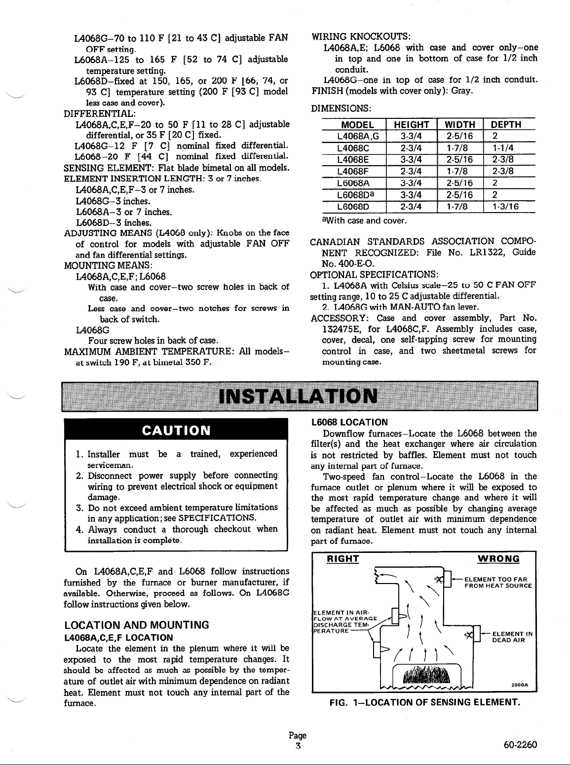
LOCATION AND MOUNTING
L4068A,C,E,F LOCATION
Locate the element in the plenum where it will be
exposed to the most rapid temperature changes. It
should be affected as much as possible by the temperature of outlet air with minimum dependence on radiant
heat. Element must not touch any internal part of the
furnace.
L6068 LOCATION
Downflow furnaces-Locate the L6068 between the
filter(s) and the heat exchanger where air circulation
is not restricted by baffles. Element must not touch
any internal part of furnace.
Two-speed fan control-Locate the L6068 in the
furnace outlet or plenum where it will be exposed to
the most rapid temperature change and where it will
be affected as much as possible by changing average
temperature of outlet air with minimum dependence
on radiant heat. Element must not touch any internal
part of furnace.
ELEMENT TOO FAR
FROM HEAT SOURCE
ELEMENT IN AIR
FLOW AT AVERA
ELEMENT IN
FIG. I-LOCATION OF SENSING ELEMENT.
Page
3
60-2260
Page 4

MOUNTING L4068A,C,E,F; L6068
NOTE: If the existing element mounting is suitable,
proceed to step 7. If existing mounting is unsuitable,
install the case as follows.
1. Make opening in plenum. See Figs. 2 and 3 for
dimensions. If modifying existing opening which is
too small, enlarge it. If existing opening is too large,
use an asbestos gasket to decrease hole size, or cover
opening with a piece of sheetmetal and cut a new hole.
NOTE: Manual fan lever on L4068E,F has a break-
awav arm. If cover to be used has no fan lever
opening, snap off lever by bending with fingers before placing cover on control.
L4068G LOCATION AND MOUNTING
The L4068G is mounted on any convenient stud or
rafter in the attic. Mount the L4068G at the selected
location using two screws through the mounting holes at
the back of the case. Mount as shown in Fig. 4.
FIG. S-MOUNTING DIMENSIONS IN INCHES [MIL-
LIMETRES IN BRACKETS] FOR L4068A,E
AND L6068A WITH CASE AND COVER.
FIG. 3-MOUNTING DIMENSIONS IN INCHES LMIL-
LIMETRES IN BRACKETS] FOR L4068C.F
AND L6068D WITHOUT CASE AND COVER.
2. Remove cover from case.
3. Position case over plenum opening and mark
mounting holes.
4. Drill or punch holes for mounting screws.
5. Remove knockouts from case.
6. Using two sheetmetal screws furnished, fasten
case to plenum or furnace.
7. Insert element into plenum.
8. Fasten control securely to furnace or case using
backplate mounting screw.
9. After wiring and adjustments are complete,
replace cover.
6748
FIG. 4-MOUNTING THE L4068G IN THE ATTIC.
WIRING
All wiring must agree with applicable electrical codes
and ordinances.
L4068A,C,E,F; L6068
Follow any wiring instructions furnished with heating
system. In a replacement installation, make certain the
L4068 or L6068 is wired in the system to operate the
same way as the old control.
NOTE: Two common terminals (with internal jumper)
are provided so that power may be provided to the
line voltage limit switch without splicing. Connect
the “hot” wire from the power supply to the upper
left terminal. On L4068, connect the fan motor to
the bottom terminal (marked LOAD); connect limit
switch, if wired in the line voltage circuit, to the
upper right terminal. Figs. 5-10 show typical wiring
diagrams.
Page
4
Page 5

FIG. 5-TYPICAL WIRING FOR L4066A,C,E,F
USED IN FORCED AIR HEATING SYSTEM.
24 VOLT
THERMOSTAT
COMBINATION
FAN AND LIMIT
TO GAS VALVE
PROVIDE DISCONNECT MEANSAND OVERLOAD PROTECTION
A
AS REQUIRED.
CONTROLCIRCUIT
Z001A
FIG. 8-TYPICAL WIRING CONNECTIONS FOR
16068 USED AS A SECONDARY LIMIT AT
THE FILTER OF A DOWNFLOW FURNACE.
R-W MAKES, R-B BREAKS ON TEMPERA-
TURE RISE TO SET POINT.
ONTROLLER
NTERMITTENT
GNITION OIL
IURNER PRIMAR
BURNER MOTOR FAN MOTOR
PROVIDE DISCONNECT MEANS AND OVERLOAD PROTECTION
AS REQUIRED.
2 FOR 24 VOLT GAS SYSTEMS. CONNECT THE PRIMARY SIDE
n
OF THE TRANSFORMER AT THE MARKED LOCATIONS. SEE
GAS VALVE INSTRUCTIONS FOR COMPLETlON OF WIRING.
2803A
FIG. 6-TYPICAL OIL BURNER SYSTEM WITH
LIMIT SWITCH IN LINE VOLTAGE CIRCUIT.
POWERPILE
PI LOT
GENERATOR
CONTROLLER
L4068
FAN
CONTROLLER
r
A FAN
/\
CONTROLLER
FAN MOTOR
28008
L6068 2
POWER
SUPPLY
HIGH LIMIT
CONTROLLER
TRANSFORMER
TO GAS-VALVE
CONTROL CIRCUIT
PROVIDE DISCONNECT MEANS AND OVERLOAD PROTECTION
A
AS REQUIRED.
2 L6068 SET POINT MUST BE HIGHER THAN FAN CONTROLLER
A
SET POINT.
FIG. g-TYPICAL WIRING CONNECTIONS FOR
L6068 USED TO CONTROL A TWO-SPEED
FAN MOTOR. R-W MAKES, R-B BREAKS ON
TEMPERATURE RISE TO SET POINT.
L4068G
Wire L4068G to turn on the fan when attic tempera-
ture rises to control point. See Fig. 4.
~~~~~T~
TWO WIRE
POWERPILE
THERMOSTAT
1 PROVlDE DISCONNECT MEANS AND OVERLOAD PROTECTION
n
AS REQUIRED.
FIG. 7-TYPICAL SELF-POWERED GAS SYSTEM
WITH LIMIT SWITCH IN MILLIVOLT CIRCUIT AND FAN SWITCH IN LINE CIRCUIT.
MOTOR
ppp:Y
POWER
2802A
Page
5 60-2260
1 POWER SUPPLY. PROVIDE OVERLOAD PROTECTION AND DISCONNECT
n
MEANS AS REQUIRED.
rra,
FIG. IO-WIRING L4068G TO CONTROL AN ATTIC
FAN.
Page 6

CONNECTING TO PUSH-IN TERMINALS
To connect the push-in terminals use the following
procedure:
1. No. 14, 16, or 18 solid or No. 14 or 16 stranded
wire may be connected to these terminals. Do not connect aluminum wire to the push-in terminals on this
device.
2. Strip insulation from wires the exact length shown
by the strip gauge on the front of the switch.
3. If stranded wire is used, insert a small screwdriver
into the rectangular hole (marked ,) on the front of
the switch above the round terminal hole; push inward
and hold. Insert wire into round terminal hole and remove screwdriver (Fig. 5). If solid wire is used, it may
be inserted into the round terminal hole without using a
screwdriver.
To disconnect either stranded or solid wire, proceed
as follows:
1. Insert a screwdriver into the rectangular hole
(marked ,) on the front of the switch. Push inward
to release grip on wire.
2. With grip released, pull wire out of round terminal
hole.
PUSH SCREWDRIVER IN AND
“OLD TO RELEASE WIRE
MOUNTING HOLE (2)
(CASE AND COVER
PUSH-IN RELEASE
PVSH-IN
TERMINALS
“FAN OFF”
ADJUSTMENT KNOB
A
FAN DIFFERENTIAL
KNOB
FIG. II-INTERNAL VIEW OF L4068 FAN CON-
TROL, SHOWING USE OF PUSH-IN
TERMINALS.
BEFORE ADJUSTING SET POINT KNOB, MAKE
SURE INSULATOR FLAP COVERS TERMINAL
SCREW BELOW KNOB.
PUSH IN TERMINAL (31
R AND RARE COMMbf.4
-SET PO, NT
BACKPLATE
MOUNTING SCREW
WIRING KNOCKOUT (2)
FIG. 12-INTERNAL VIEW OF L6068,SHOWING USE
OF PUSH-IN TERMINALS.
L4068G
On L4068G, the fan differential is fixed at 12 F [ 7 C]
nominal. The fan will start when attic temperature rises
about 12 F [7 C] above the FAN OFF setting. For
example, when the FAN OFF setting is 85 F [29 C] , the
fan will start at about 85 F [ 29 C] plus 12 F [ 7 C] , or
about 97 F [36 C] .
L4068 SETTINGS
FIXED DIFFERENTIAL
L4068A,C,E,F
On some models, the differential is fixed at approxi-
mately 35 F [ 20 C] . The fan starts when the plenum
temperature rises 35 [ 20 C] degrees above the FAN OFF
setting. For example, when the FAN OFF setting is
100 F [38 C], the fan starts at approximately 100 plus
35 or 135 F [38 plus 20 or 58 C] .
ADJUSTABLE DIFFERENTIAL (L4068A,C,E,F)
Models with adjustable differential may be set between
20 and 50 F [ 11 to 28 C] . Differential is factory-set at
25 F [ 14 C] . The fan starts when the plenum temperature
rises to the FAN OFF setting plus the differential
setting. For example, when the FAN OFF setting is
100 F [38 C] and the differential is set at 25 F [ 14 C] ,
fan starts when temperature rises to 125 F [52 C] and
stops when temperature drops to 100 F [ 38 C] . Changing
the differential changes the FAN ON temperature only.
Page
6
Page 7

‘v
FAN OFF SET POINT
Set FAN OFF to temperature recommended by burner
or attic fan manufacturer. On replacement installations,
use temperature set on old control.
NOTE (L4068A,C,E,F): If the fan runs too long after
burner shutdown (as evidenced by cold drafts), raise
the FAN OFF setting. Raising the FAN OFF setting
simultaneously raises the FAN ON setting by the same
amount. If the fan does not run long enough after
burner shutdown (as evidenced by recycling), lower
the FAN OFF setting.
L6068 SETTING
The L6068 switch makes R-W and breaks R-B when
the temperature at the sensing element rises to the
set point. When the temperature falls 20 F [ 11 C] below
the set point, the switch breaks R-W and remakes R-B.
On the L6068A the set point is adjustable from 125
to 165 F [52 to 74 C] ; turn the knob on front of the
switch until indicator points to the temperature, at
which the switch should break R-B and make R-W.
heat. The burner should come on and the limit control
should shut off the burner when the plenum temperature
reaches the limit control set point. Reconnect the fan.
Again set the thermostat to call for heat. The burner
should come on and the fan should come on when the
plenum temperature reaches the FAN ON set point.
L4068G -
After mounting and wiring are complete, turn on the
power supply and turn FAN OFF setting more than 12 F
[7 C] below attic temperature. Fan should come on.
Turn setting dial above attic temperature. Fan should go
off. Reset control to desired FAN OFF setting.
L6068 USED AS A SECONDARY LIMIT CONTROL
After completing mounting and wiring, turn on the
power supply and let the system operate through one
complete cycle. Actuate the control by blocking the
filter until the temperature reaches the set point of
the L6068. At this point the furnace should cut out
and the fan should start or continue operating.
\--_/
CHECKOUT
L4068A,C,E,F
After mounting and wiring are complete, turn on the
power supply and allow the system to operate through
one complete cycle. To check the furnace limit control,
disconnect the fan and set the thermostat to call for
L6068 USED AS A TWO-SPEED FAN CONTROL
After mounting and wiring are completed, turn on
power supply. Set thermostat to call for heat. Fan
should first come on low speed. After a short period
of operation, the L6068 should change the fan speed to
high.
HONEYWELL MINNEAPOLIS, MINN. 55408 INTERNATIONAL Sales Offices in all principal cities of the world. Manufacturing in
Australia, Canada, Finland, France, Germany, Japan, Mexico, Netherlands, Spain, Taiwan, United Kingdom, U.S.A.
PRINTED IN U.S.A.
 Loading...