

Page 1
KS20S
Read carefully before starting up!
Leggere attentamente prima della messa in servizio!
Keep instructions for later use!
Conservare le istruzioni per uso futuro!
32303398 Rev. A
Operation Manual Manuale operativo
KaltecSoft Evolution
Water softener Addolcitore d’acqua
Page 2

Page 3

Honeywell GmbH 1 MU5H-1419GE23 R0815
Table of Content
1 Introduction ...........................................................................................................................3
2 Safety guidelines ...................................................................................................................3
3 Scope of delivery ...................................................................................................................4
4 Description of function ...........................................................................................................4
4.1 Meter regeneration .....................................................................................................4
4.2 Valve operation ..........................................................................................................4
4.3 Application ..................................................................................................................4
4.4 Sodium concentration limit .........................................................................................5
5 Technical data .......................................................................................................................5
6 Installation Instructions ..........................................................................................................8
6.1 General advices .........................................................................................................8
6.2 Mounting .....................................................................................................................8
6.3 Residential installation ................................................................................................9
7 Start-up .................................................................................................................................9
7.1 Start-up instructions ....................................................................................................9
7.2 Valve positions .........................................................................................................10
8 Setting .................................................................................................................................11
8.1 General parameters ..................................................................................................11
8.2 Time of the day .........................................................................................................11
8.3 Basic settings ...........................................................................................................12
8.4 Programming - Advanced Installers .........................................................................13
8.5 Basic settings ...........................................................................................................13
8.6 System parameters ..................................................................................................14
9 History .................................................................................................................................15
9.1 History data mode ....................................................................................................15
9.2 Flow rate ...................................................................................................................16
9.3 Regeneration data ....................................................................................................16
9.4 Error log ....................................................................................................................16
10 Maintenance ........................................................................................................................16
10.1 Preparation ............................................................................................................... 16
10.2 Cleaning ...................................................................................................................17
10.3 Spare part sets .........................................................................................................17
10.4 Maintenance log .......................................................................................................18
11 Troubleshooting ..................................................................................................................19
12 Disassembly .......................................................................................................................21
13 Disposal .............................................................................................................................21
Page 4

Honeywell GmbH 2 MU5H-1419GE23 R0815
Contenuto
1 Introduzione ........................................................................................................................23
2 Avvertenze di sicurezza ......................................................................................................23
3 Fornitura ..............................................................................................................................24
4 Descrizione del funzionamento ...........................................................................................24
4.1 Rigenerazione tramite contatore ..............................................................................24
4.2 Funzionamento della valvola ....................................................................................24
4.3 Modalità di impiego ...................................................................................................24
4.4 Concentrazione massima di sodio ............................................................................25
5 Dati tecnici ...........................................................................................................................25
6 Istruzioni di installazione .....................................................................................................28
6.1 Avvertenze generali ..................................................................................................28
6.2 Montaggio .................................................................................................................28
6.3 Installazione domestica ............................................................................................29
7 Messa in servizio .................................................................................................................29
7.1 Istruzioni per la messa in servizio .............................................................................29
7.2 Posizioni della valvola ..............................................................................................30
8 Configurazione ....................................................................................................................31
8.1 Parametri generali ....................................................................................................31
8.2 Ora del giorno ...........................................................................................................32
8.3 Impostazioni di base .................................................................................................32
8.4 Programmazione (per installatori esperti) .................................................................33
8.5 Impostazioni di base .................................................................................................33
8.6 Parametri di sistema .................................................................................................35
9 Storico .................................................................................................................................36
9.1 Modalità dati dello storico .........................................................................................37
9.2 Portata ......................................................................................................................37
9.3 Dati relativi alla rigenerazione ..................................................................................37
9.4 Registro degli errori ..................................................................................................38
10 Manutenzione ......................................................................................................................38
10.1 Preparazione ............................................................................................................ 38
10.2 Pulizia .......................................................................................................................38
10.3 Set di ricambi ............................................................................................................38
10.4 Libretto di manutenzione ..........................................................................................39
11 Guasti / Ricerca guasti ........................................................................................................40
12 Smontaggio ........................................................................................................................43
13 Smaltimento .......................................................................................................................43
Page 5
MU5H-1419GE23 R0815 3 Honeywell GmbH
English
We would like to thank you for choosing the KS2 0S softener.
We are convinced that our product will serve you to your
complete satisfaction as it has been manufactured with
extreme care.
The KS20S softener is delivered in a box and includes a
bypass valve. Please carefully inspect the device in presenc e
of deliveryman for transportation damages.
Your Honeywell team
1. Introduction
This manual is intended for professional installers. Please
read this manual to ensure a danger-free, safe and correct
commissioning of the KS20S softener.
Safety information and notes are characterised b y symbols in
this manual.
2. Safety guidelines
Warning! Indicates a potentially hazardous situation
which, if not avoided, could result in death or serious
injury.
Caution! Indicates a potentially hazardous situation
which, if not avoided, could result in minor or moderate
injury or damage to property.
Note! Provides supplementary information or gives
tips for easier operation
Note! Environment protection guidelines
Caution! Before starting up the softener, read this
manual carefully. Handle the softener carefully.
Caution! Keep this instructions for later use.
Caution! Use the softener only according to desig-
nated application.
Caution! Do not perform a total reset of settings. The
device can be used in its full performance only with the
factory settings.
Caution! Keep the softener in proper working order.
Caution! Any malfunctions must be repaired at once
by a professional installer.
Caution! Install a pressure reducer ahead of the
softener, if the input pressure is more than 6bar.
Caution! Ensure that installation is not subject to free-
zing or extreme heat. Avoid exposure to sun.
Caution! Install the softener in a chos en place on a flat
firm and clean surface.
Warning! Do not touch any electrical parts with wet
hands! Disconnect the softener for any electrical works
Warning! Place the power cord carefully to avoid tripping hazard!
Warning! Beware of tripping or slipping hazard due to
escaping media!
Note! Both the softener and the associated packaging
consist mostly of recyclable raw materials. Dipose of
packing and recyclable materials separately, properly
and in environmentally friendly way.
Page 6
Honeywell GmbH 4 MU5H-1419GE23 R0815
3. Scope of delivery
All models of the KS20S softener are delivered in a box
containing:
• KS20S water softener
• Installation instruction
• Chlorinator (mounted ex works)
• Bypass valve with blending
• Inlet check valve (mounted ex works)
• Reinforced hose for inlet/outlet connection
- 2 hoses, length 650 mm, 1" felmale/female
-4 washers
- Connection pieces
• Pipe for drain and regeneration water
- Length 3000 mm
- Diameter 1/2"
- Connection kit (2 screw lamps, hose coupling, washer)
• Test kit for water hardness
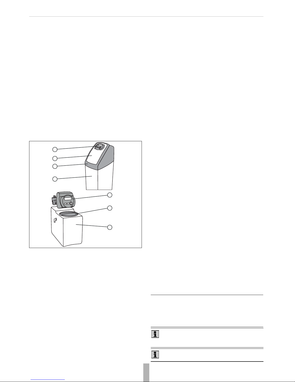
Main components
Img. 1 KS20S main components
The KS20S softener consists of the following main components:
1. Controller
2. Brine lid
3. Main hood
4. Brine tank
4. Description of function
4.1. Meter regeneration
In normal use the LCD display alternates between following
indications:
• Time of day
• Remaining capacity (m
3
)
•Flow rate
• Number of days until next regeneration
• Installer name
• Softener name.
At the time of regeneration the controller compares the remaining capacity with the reserve and decides if it is necessary to
start the regeneration. KS20S softener is equipped with a
blending device to insure a residual hardness in softened
water.
Controller
During regeneration the LCD display alternates between
following indications:
• Cycle number
•Cycle name
• Remaining time for the current cycle.
When all the cycles are finished, the valve comes bac k to the
service position.
The controller of KS20S softener can manage:
• Normal brining
• Proportional brining
• Counter current regeneration (upflow ).
4.2. Valve operation
The bypass valve of KS20S softener can be set in different
positions (see 7.2. Valve positions):
• Normal operation
• Bypass
• Diagnostic bypass
• Shut off.
Setting Mode
To enter the program mode put the valve to the normal operation position. During and after the sett ing (see 8. Setting), the
valve will continue to operate normally monitoring all information. The settings are stored in permanent memory.
Power failure
During a power failure the controller of KS20S softener will be
inoperative and any calls for regeneration will be delayed.
The controller will continue normal operation fr om the point of
interruption once the power supply is resumed.
All control display s an d programming will be stored during a
power failure for a later use when the power supply is
resumed. The control will retain these values without loss, if
necessary, for years.
4.3. Application
Honeywell recommends the following applications of KS20S
softener:
1
2
4
3
1
2
4
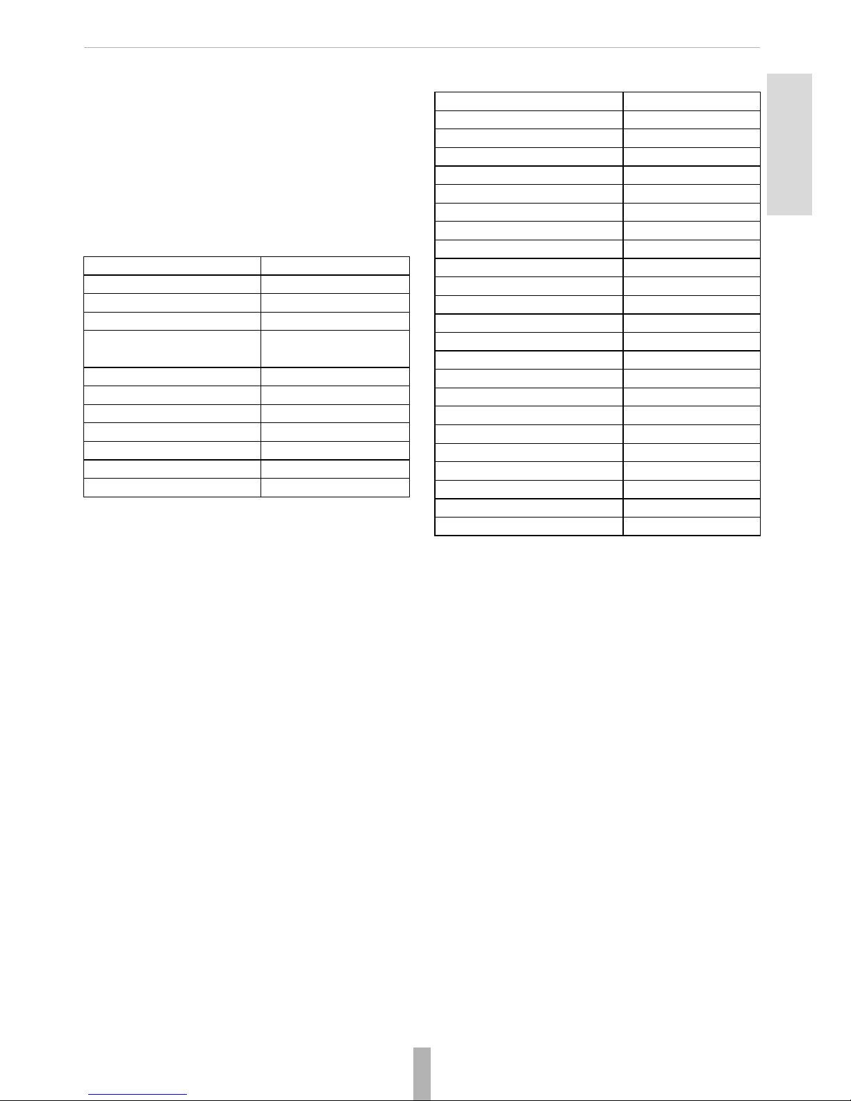
Type Size Honeywell recommendations
KS20S-15 5 liters 1 point-of-use application (e. g. one sin k)
KS20S-45 14 liters 1-4 family dwelling
KS20S-55 18 liters 3-8 family dwelling
KS20S-85 25 liters 6-21 family dwelling
Note! Values recommended for households with a
water hardness of 30 f°H and an average daily
consuption of 0,1m3 water per person.
Note! Honeywell recommends to install a 100µcartridge filter.
Page 7
MU5H-1419GE23 R0815 5 Honeywell GmbH
English
4.4. Sodium concentration limit
When operating a KS20S softener, the limit value for the
sodium concentration (acc. drinking water ordinance) of
200 mg/l may not be exceeded.
To reduce the water hardness by 1°fH, add about 4,5 mg/l
sodium to the water. Additionally, take into ac count the basi c
sodium content of the raw water. The maximum possible
softening results from these values.
5. Technical data
Remarks
(*) without nods and open at athmospheric pressure
(**) under normal circumstances
KS20S Models:
The further technical paramete rs differ from the size and the
model of the KS20S softener.
Connection IN&OUT 1"
Drain connection (*) 3/4"
Electrical rating 230V, 50Hz, 12 V
Max power rating 6W
IP protection class IP 51, double isolated
transformer
Nominal pressure PN10
Min inlet pressure 2 bar
Max inlet pressure 8 bar
Vacuum no allowance
Average pressure loss (**) 1 bar
Min water temperature 5 °C
Max water temperature 35 °C
KS20S-15
height 530mm
width 230mm
depth 430mm
height IN&OUT 513mm
max. weight 30kg
KS20S-45
height 730mm
width 320mm
depth 530mm
height IN&OUT 50mm
max. weight 70kg
KS20S-55
height 1070mm
width 320mm
depth 530mm
height IN&OUT 82mm
max. weight 129kg
KS20S-85
height 1180mm
width 320mm
depth 530mm
height IN&OUT 96mm
max. weight 178kg
Page 8

Honeywell GmbH 6 MU5H-1419GE23 R0815
Technical data:
KS20S-15
Ion exchange
Capacity kg CaCO
3
0,15
°F x m
3
15
°dH x m
3
8
salt consumption kg salt/regen. 0,5
kg CaCO
3
/kg salt 0,3
Flow rate
nomial m
3
/h 0,30
peak m
3
/h 0,4
minimum L/h 60
Rinse water consuption
brining & slow rinse liters 15
backwash liters 5
fast rinse liters 20
total liters 40
L/kg CaCO
3
267
KS20S-45
Ion exchange
Capacity kg CaCO
3
0,83
°F x m
3
83
°dH x m
3
47
salt consumption kg salt/regen. 1,8
kg CaCO
3
/kg salt 0,4
Flow rate
nomial m
3
/h 1,2
peak m
3
/h 1,7
minimum L/h 60
Rinse water consuption
brining & slow rinse liters 25
backwash liters 40
fast rinse liters 20
total liters 85
L/kg CaCO
3
102
Page 9

MU5H-1419GE23 R0815 7 Honeywell GmbH
English
Technical data:
KS20S-55
Ion exchange
Capacity kg CaCO
3
1,04
°F x m
3
104
°dH x m
3
58
salt consumption kg salt/regen. 2,2
kg CaCO
3
/kg salt 0,4
Flow rate
nomial m
3
/h 1,4
peak m
3
/h 1,7
minimum L/h 60
Rinse water consuption
brining & slow rinse liters 35
backwash liters 30
fast rinse liters 20
total liters 85
L/kg CaCO
3
82
KS20S-85
Ion exchange
Capacity kg CaCO
3
1,61
°F x m
3
161
°dH x m
3
90
salt consumption kg salt/regen. 3,4
kg CaCO
3
/kg salt 0,4
Flow rate
nomial m
3
/h 1,8
peak m
3
/h 2,3
minimum L/h 60
Rinse water consuption
brining & slow rinse liters 45
backwash liters 5
fast rinse liters 35
total liters 120
L/kg CaCO
3
75
Page 10
Honeywell GmbH 8 MU5H-1419GE23 R0815
6. Installation Instructions
6.1. General advices
Location
When you choose the softener location, please take into
account the following parameters:
• Install the KS20S softener in a chose n plac e on a f lat firm
and clean surface.
• The KS20S softener must be close to a drain line to allow
an easy connection.
• Make sure there is an electrical earth grounded plug to
power the unit.
Pressure
A minimum pressure of 2 bar is needed to allow the valve to
regenerate properly. Please do not operate over 8bars.
If this is the case, use a pressure reducer upstream of the
installation.
Power connection
Be sure that power cannot be switched off accidentally at
a wall switch. If the power cable is damaged, please ask a
professional electrician to change it.
Plumbing
The plumbing must be in good state. In case of doubt, please
change it. We advise the use of prefilter upstream the installation.
All plumbing for the water inlet, distribution and drain lines
should be done correctly in accordance with the legis lation in
force at the time of the inst allation. The pipe size for the drain
line should be a minimum of 20mm (3/4’’).
To prepare for any maintenance:
1. Shut down water inlet
2. Unplug the KS20S soft ener
3. Drain the installation by opening the taps at the highest
and the lowest level of your house.
Water Temperature
6.2. Mounting
1. Thoroughly flush pipework.
2. Install the KS20S sof tener.
• Note flow direction (indicated by arrow).
• Install without tension or bending stresses.
3. Establish the conn ections to the KS20S softener.
4. Connect the sew e rage tube to the discharge connection
(inner tube ømin. 13 mm, 1/2").
Caution! The installation must be performed by a
professional installer only.
Caution! It is seriously recommended to ins tall a pressure reducer ahead of the softener, if the input pressure is more than 6 bar. Failing to adhere to this saf ety
note can cause irreversible damage.
Caution! During cold weather, bring the softener to
room temperature before operation.
Caution! During hot weather, do not install t he softener
in direct sunlight or in a room with a temperature
above 45°C.
Warning! All electrical and plumbing installations
should be performed by professional electric ians and
installers in accordance with all local codes.
Caution! Finish all the soldering on t he main plumbing
and on the drain, before connecting the softener.
Failing to adhere to this safety note can cause irreversible damage to the KS20S.
Caution! Inlet water temperature must not exceed
35° C. Complete installation must not be allowed to
freeze. Failing to adhere to this safet y note can cause
irreversible damage to the KS20S.
Caution! Finish all welding and soldering works in the
near vicinity to the softener before mounting.
Failing to adhere to this saftey note can cause irreversible damage.
Caution! Make sure the seal is fitted properly!
Page 11
MU5H-1419GE23 R0815 9 Honeywell GmbH
English
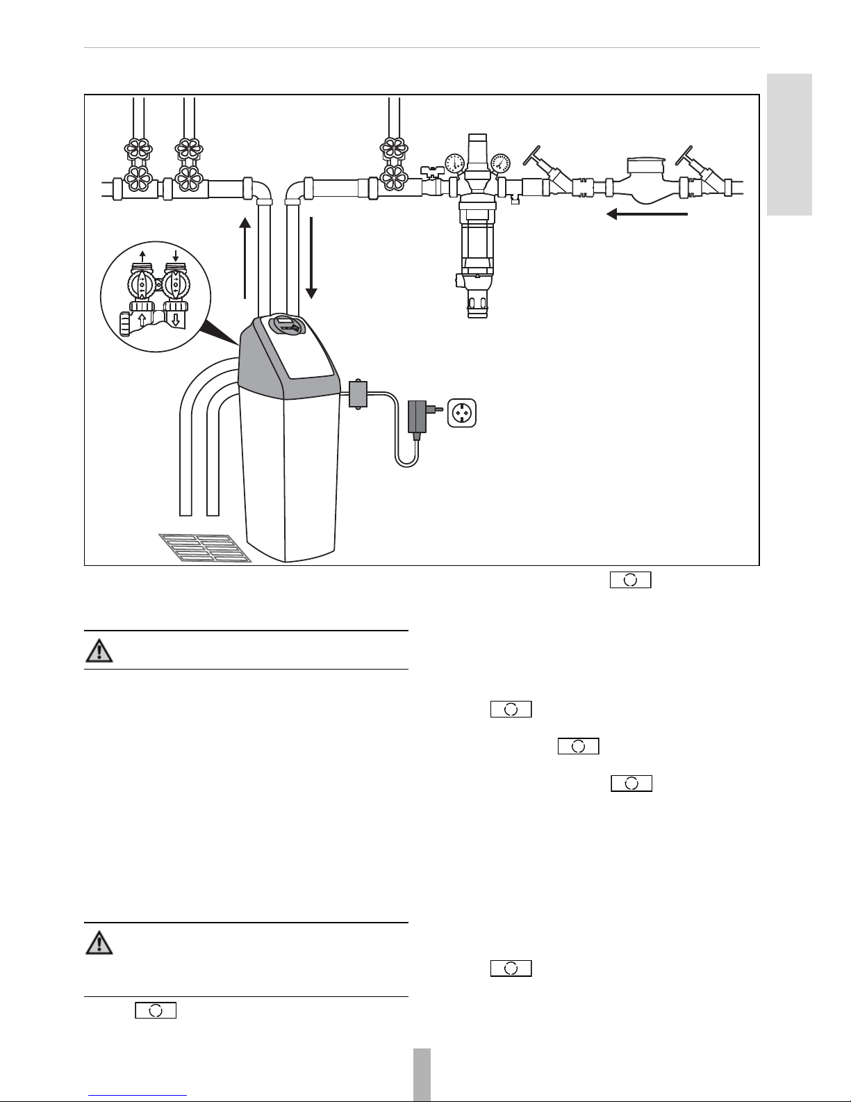
6.3. Residential installation
Img. 2 Residential installation (Example)
The black lines represent the direction of water f low.
7. Start-up
7.1. Start-up instructions
1. Manually add water in brine tank above the aircheck
(around 10 liters)
Do not fill with salt at the moment.
2. Place the valves int o the byp ass po sition (s ee 7.2 . Valve
positions).
3. Turn on the main water supply.
4. Open a cold water tap downstream of the KS20S
softener. Let the water run a few minutes until the KS20S
softener is free from any foreign material (usua lly solder)
that may have resulted from the installation.
5. Once the softener is clean, close the water tap.
6. Switch on the power.
7. Push and hold it down for 3seconds. The system
will advance to the "first" position
8. When the moto r stops, pu sh repeatedly until the
display shows "RINSE".
9. Slowly t urn the bypass valve to close the outlet and open
the system inlet.
10. Run water to the drain until it runs clear.
11. Place the KS20S softener in the bypass position (syst em
inlet-outlet closed – full bypass).
12. Push until the KS20S softener is back in to
softening mode.
13. Once again, push and hold it down for
3 seconds.
14. When the motor stops, push repeatedly until the
display shows "BACKWASH".
15. Slowly open the inlet bypass valve 1/2 way to feed the
softener with water. Allow water to slowly fill the tank.
16. When a solid stream of water starts coming out of the
drain line, open the inlet b ypass valve all the w ay. Let the
water drain until its clean.
17. Slowly place the bypass valve into "Normal position" (see
7.2. Valve positions) by opening the outlet side of bypass
valve. Now the system inlet-outlet is open.
18. Push until the display shows "REGENERANT
DRAW DN" or "REGENERANT DRAW UP".
19. Carefully check the water level in the brine tank.
If it decreases, skip to the next step or see the section
“Troubleshooting” on page19.
Caution! The start-up must be performed by a professional installer only.
Note! Once put under electrical power, the valve may
automatically run a cycle in order to ge t into the service
position. Display will alternate between installer name,
time of day, flow rate and remaining capacity.
Page 12
Honeywell GmbH 10 MU5H-1419GE23 R0815
20. Push again until the display shows "RINSE".
Allow the rinse cycle to run its full course.
21. While the rinse cycle is finishing, load brine tank with salt.
22. If the refill cycle is at the end of the regeneration cycle,
add around 10 liters of water to allow the first regeneration.
23. Go to section “Programming - Advanced Installers” on
page 13.
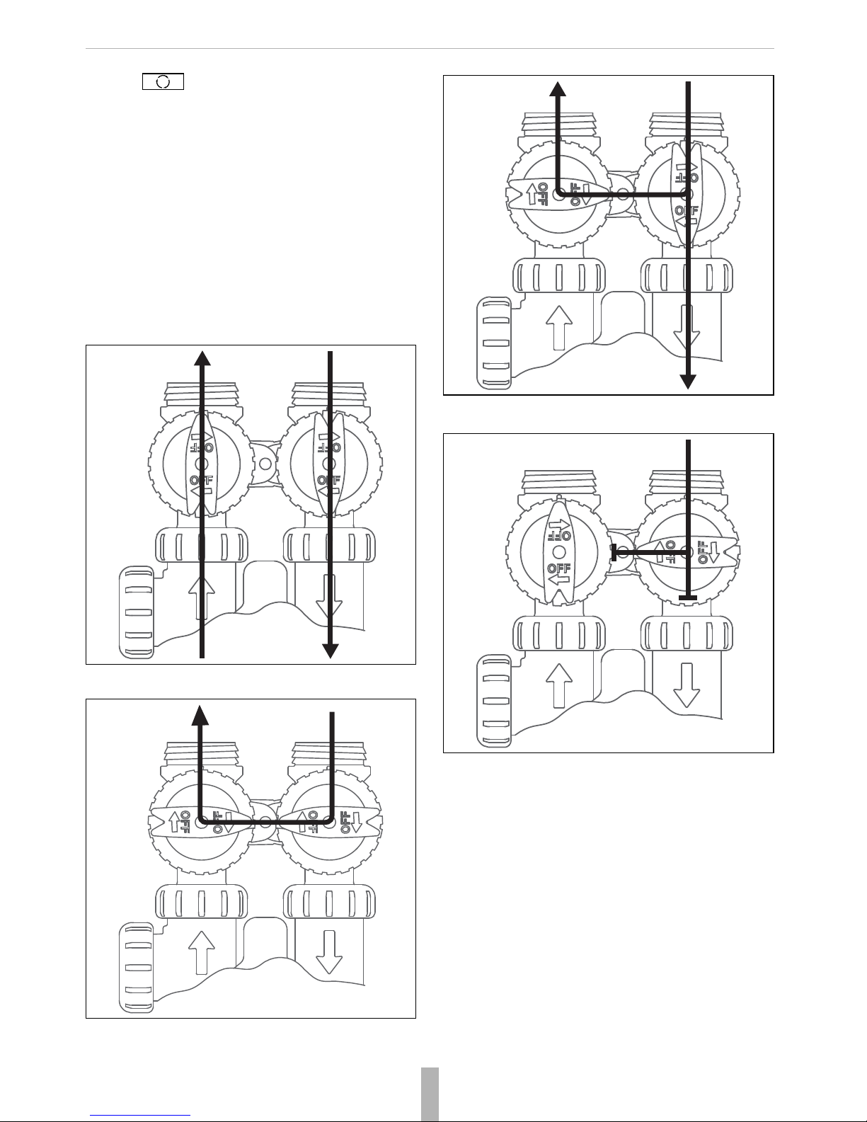
7.2. Valve positions
The bypass valve provided by with the KS20S softener can
be set into four different positions dep ending on th e selected
mode. The following four images depict the valve positions
and the water ways (in/out) within the valve.
Img. 3 Normal position operation
Img. 4 Bypass position
Img. 5 Diagnostic position
Img. 6 Shut-off position
Page 13

MU5H-1419GE23 R0815 11 Honeywell GmbH
English
8. Setting
Display and operating keys
Img. 7 Display and operating keys
1. Confirmation of water flow (detected from water meter)
2. Name of parameter
3. Value of parameter
4. "Confirm and Go ahead" but ton
5. Decreasing butt on
6. Increasing button
7. Regeneration but ton / back button
8. Clock button
8.1. General parameters
The initial display shows general parameters alternating
between TIME OF DAY, CAPACITY REMAINING, DAYS TO
A REGEN, FLOW RATE and Installer name and phone
number, if set
1. Push to start scrolling through the parameters.
2. Each push on displays another parameter in the
following sequence:
• CAPACITY REMAINING
• DAYS TO REGEN
•FLOW RATE
• Installer name and phone number, if set.
8.1.1. CAPACITY REMAINING
You can change the remaining capacity of the KS20S
softener.
1. Push to go to the next parameter
The display shows CAPACITY REMAINING.
2. Push to decrease the capacity.
Each push decreases the capacity by 0.01m³
8.1.2. DAYS TO REGEN
You can change the number of days till the next regeneration .
1. Push to go to the next parameter
The display shows DAYS TO REGEN
2. Push to decrease the number of days.
Each push decreases the days until the next regeneration
by 1.
8.1.3. FLOW RATE
The current flow rate of the KS20S softener is shown in LPM
(liters per minute).
8.1.4. Installer data
The display will show the name and the phone nu mber of the
installer, if set.
8.2. Time of the day
1. Push to set the time
The display shows TIME HOUR and the current hour flas hes.
2. Push or to adjust the hours.
3. Push to go to the next parameter.
Note! An asterix (*) is displayed, if the water meter
detects a water flow.
Note! TIME OF DAY alternates with REGEN TODAY,
if a regeneration is expected today.
1 2 3
4568 7
Page 14

Honeywell GmbH 12 MU5H-1419GE23 R0815
The display shows TIM E M INUTES and the current minutes
flash.
4. Push or to adjust the minutes.
5. Push to exit the settings.
The display shows TIME OF DAY or another general parameter (see 8.1. General parameters).
8.3. Basic settings
8.3.1. Water hardness
1. Push and hold for 3 seconds both buttons and
until the display shows RAW HARDNESS.
2. Push or to change raw water hardness.
3. Push to go to the next parameter.
8.3.2. Service (Residual) hardness
The display shows SERVICE HARDNESS
1. Push or to change raw water hardness in
the unit selected during the start-up. 15°fH is set as
default parameter.
2. Push to go to the next parameter.
8.3.3. Regeneration time
The display shows DAYS BETWEEN REGEN.
1. Push or to set up number of days between
two regenerations.
• Default setting is "4".
• Maximum number of days is "28"
• Display indication "Off" means there is no forced regeneration.
2. Push to go to the next parameter.
The display shows REGEN TIME HOUR and the numbers
indicating the current time in hours start flashing.
1. Push or to set the regeneration time (hour).
2. Push to go to the next parameter.
The display shows REGEN TIME MINUTES and the numbers
indicating the current time in minutes start flashing..
3. Push or to set the regeneration time
(minute).
4. Push to exit the settings.
The display shows TIME OF DAY or another general parameter (see 8.1. General parameters).
8.3.4. Setting the residual water hardness
1. Set the residual water hard ness by turning the screw at
the outlet side of the control valve block
Img. 8 Water hardness screw
• Turn the screw anti-clockwise to decrease water hardness
on the output side
• Turn the screw clockwise to increase water hardness on
the output side
2. Check the mixed water hardness at a tapping point
Caution! These changings are recommended for experienced users and professional installers only.
Note! After 5 minutes without action, the contro ller switches back to the operating mode.
Caution! Do not decrease th e service hardness to less
than 15°fH to avoid corrosion.
Caution! Do not decrease the numb er of days betwee n
regenerations for hygienic reasons .
°
°
Caution! Do not decrease the service hardness to less
than 15°fH to avoid corrosion.
The manufacturer recommends to check the output
water hardness regularly (2 times a year).
Page 15
MU5H-1419GE23 R0815 13 Honeywell GmbH
English
• Open the tapping point completely to ensure a sufficient
flow
3. Readjust by turning the screw if necessary
4. Repeat the above steps until the measured value is equal
to the value set under 8.3.2. (default 15°fH).
8.4. Programming - Advanced Installers
8.5. Basic settings
The basic settings such as changing water hardness and
regeneration time are described in detail in 8.3.
8.5.1. Unlocking the set mode
To unlock the set mode press following buttons one af ter
another .
8.5.2. Locking the set mode
To lock the set mode press following buttons one after
another .
8.5.3. Setting parameters
The KS20S softener can be programmed by defining the
following parameters:
• Operating mode
•Cycle times
• Capacity
• Brine tank refill type
• Regeneration start time
• Reserve type
• Service alarm
8.5.4. Set mode
1. Push and hold for 3seconds both buttons and
until the display shows "SOFTENING".
2. Push to go to the next parameter.
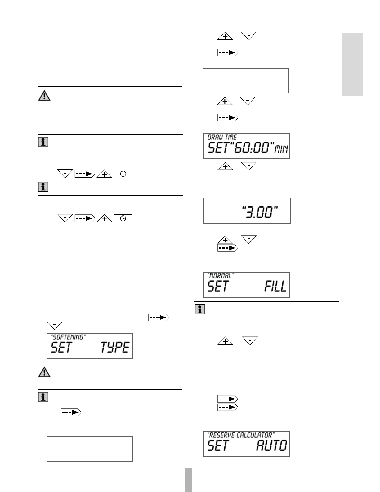
8.5.5. Cycle times
The display shows FILL TIME.
1. Push or to set up the amount of salt in kg
for cycle1 (see 8.6.4. Operation cycles).
2. Push to go to the next parameter.
The display shows SOFTENING TIME
3. Push or to set up the number of minutes for
cycle 2 (see 8.6.4. Operation cycles).
4. Push to go to the next parameter.
The display shows DRAW TIME
5. Push or to set up the parameters for
cycles 3, 4 and 5 (see 8.6.4. Operation cycles).
8.5.6. Capacity
The display shows SOFTENING CAPACITY.
• If hardness unit is f°H then capacity unit is m
3
.
6. Push or to set up the softener capacity.
7. Push to go to the next parameter.
8.5.7. Brine tank refill
The display shows FILL.
You can select between "NORMAL" and "PROPORTIONA L"
brine tank refill.
8. Push or to change between the brine tank
refill types.
• NORMAL: the unit regenerates completely.
• PROPORTIONAL (default): corresponds with ratio of
used capacity on total capacity multiplied
by refill for a complete regeneration
of resin bed.
9. Push to go to the parameter "Reserve type".
10. Push to go to the next parameter.
8.5.8. Reserve calculator
The display shows RESERVE CALCULATOR
Caution! Programming must be perfomed by
authorized personnel only.
Note! To set the parameters the setting mode must be
unlocked!
Note! Remember to lock the set mode after the setting
of the parameters.
Caution! Do not change any settings in the FI LTERING
mode. Any changes in the FILTERING mode will
prevent the device from functioning correctly.
Note! In this manual, only the SOFTENING operating
mode is described.
Note! This pa rameter is o nly available if con figured
as a 25 mm Pre-Fill Up-Flow brining softener.
Page 16

Honeywell GmbH 14 MU5H-1419GE23 R0815
11. Push or to change between the reserve
types:
• AUTO (default): capacity and reserve are automatically
calculated.
• OFF: reserve calculato r is not active.
8.5.9. Regeneration start time
1. Push to go to the next parameter.
The display shows DELAYED.
2. Push or to select the regeneration start
time between:
• DELAYED: regeneration on a specific time
• IMMEDIATE:immediate regeneration when volume
is at 0
• DELAY+IMMEDIATE (default): delayed regeneration
with override on 0 volume
8.5.10.Service alarm
1. Push to go to the next parameter.
The display shows SERVICE ALARM.
You can set the service alarm basing on time, volume or both.
2. Push or to set the unit:
• TIME: based on time
• m³: based on volume
• BOTH: based on time and volume
• OFF: no service alarm defined
Example:
Service alarm every 3months
If set up service alarm is based on time ea ch push inc reases
or decreases the time by 3 months.
The display shows SERVICE ALARM if setting is based on
volume or both.
Example: Service alarm every 500m³
Push to go to the next parameter.
8.5.11.Scheduled service
The display shows SCHEDULED SERVICE.
For more information on scheduled service go to paragraph
10. Maintenance.
3. Push to exit the settings.
The display shows TIME OF DAY or another general parameter (see 8.1. General parameters).
8.6. System parameters
Push and hold for 3 seconds both buttons and
and repeat this for further 3 seconds until the display
shows DISPLAY and the system language flashes.
8.6.1. Language settings
1. Push or to change the language.
2. Push to go to the next parameter.
8.6.2.
Valve parameters
The display shows VALVE TYPE and the type number
flashes.
Example:
25 mm is set as default.
8.6.3. Valve body and hardness unit
1. Push or to set up the size.
2. Push to go to the next parameter.
The display shows HARDNESS UNITS.
3. Push or to set the hardness unit:
• ppm: parts per million
• °dH: German degree
• °fH: French degree, default
• NA: no hardness setting
4. Push to go to the next parameter.
°
Page 17

MU5H-1419GE23 R0815 15 Honeywell GmbH
English
8.6.4. Operation cycles
First cycle
The display shows set CYCLE 1 and the cycle type flashes.
Push to scroll through the cylces.
WS1CI Only Upflow Regenerant Refill After Rinse
• 1st cycle: Fill
• 2nd cycle: Softening
• 3rd cycle: Draw up
• 4th cycle: Backwash
• 5th cycle: Rinse
• 6th cycle: End
Last cycle
Push to go to the last cylce.
The display shows END.
Setting the contact data of the installer
1. Push and for 3 seconds to enter the level
to set the contact data of the installer.
2. Push or to change the first digit of the
telephone number of the installer.
3. Push to go to the next digit.
4. Push to set the name of the installer.
5. Push or to change the first letter of the
name of the installer.
6. Push to go to the next letter .
7. Push to exit the settings.
The display shows TIME OF DAY or another general parameter (see 8.1. General parameters).
To lock the set mode please see 8.5.2. Locking th e set mode.
9. History
The KS20S softener saves the follwing parameters in controller history:
• Number of days since the last regeneration
• Salt consumtion since the last regenetation
• Salt consumption since start-up
• Total number of regenerations since start-up
• Reserve history
• Usage history
• Maximum flow rate in the last 7 days
9.1. History data mode
Push and hold for 3secondes both buttons and
until the display shows DAYS SINCE REGEN, the
number of days since the last regeneration.
9.1.1. Consumption - last regeneration
Push to go to the next parameter.
The display shows SINCE LAST REGEN, the consumption in
m³ since last regeneration.
Push to go to the next parameter.
9.1.2. Usage history
The display shows USAGE HISTORY.
1. Push or to show the usage history on a
certain day. You can choose between day 1 and 63.
2. Push to go to the next parameter.
Caution! Do not change the operation cycles or their
order. Any changes of the oper ation cycles will prevent
the device from functioning correctly.
Caution! Do not change t he contro l valves from downflow to upflow brining or vice versa.
The valve bodies for downflow and upflow are unique
to the regeneration type and should not be interchanged. A mismatch of valve body and regeneration
piston will result in hard water bypass during service.
Note! Maximum number of digits to set is eleven.
Note! Maximum number of digits to set is eighteen.
Note! Remember to lock the set mode after the setting
of the parameters.
Day 1
Day 2
:
Day 63
Yesterday
The day before yesterday
:
63 days before
Page 18

Honeywell GmbH 16 MU5H-1419GE23 R0815
9.1.3. Reserve history
The display shows RESERVE HISTORY.
Reserve history (at the time of regeneration):
3. Push to exit the settings.
The display shows TIME OF DAY or another general parameter (see 8.1. General parameters).
9.2. Flow rate
The display shows MAX FLOW.
The display shows the maximum flow rate of the last 7days.
1. Push and hold for 5seconds both buttons and
to reset the flow rate.
2. Push to exit the settings.
The display shows TIME OF DAY or another general parameter (see 8.1. General parameters).
9.3. Regeneration data
1. Push and hold twic e for 3seconds both buttons
and .
The display shows TOTAL DAYS - the total number of days
since start up.
2. Push to go to the next parameter.
The display shows TOTAL REGENS - the total number of
regenerations since start up.
3. Push to go to the next parameter
The display shows TOTAL CUBIC METERS - the total
amount of used water in m³ since the start up. -
9.4. Error log
1. Push to go to the next parameter.
The display shows ERROR LOG. .
The error log includes the last10 errors generated by the
controller.
2. Push or to scroll through the list of 10.
3. Push to exit the settings.
The display shows TIME OF DAY or another general parameter (see 8.1. General parameters).
10. Maintenance
The completed maintenance wo rk needs to be documented in
the “Maintenance log” on page18.
10.1.Preparation
1. Shut down water inlet
2. Unplug the KS20S soft ener
3. Drain the installation by opening the taps at the highest
and the lowest level of your house.
Day 0
Day 1
Day 2
:
Day 6
Today
Yesterday
The day before yesterday
:
(max)
Note! Not visible in time mode, when the volume
setting is 0. The function day override triggers the regeneration.
Note! "R" is displayed if regeneration has occured in
the last 24 hours.
Note! Only available when controller is switched on.
Caution! All the maintenance works must be performed
by authorized personnel only.
Warning! Switch off the softener before the maintenance and prevent switching on without authorisation
(mains disconnection)!
Page 19

MU5H-1419GE23 R0815 17 Honeywell GmbH
English
10.2.Cleaning
Clean inside and the outside of the housing with damp cloth.
10.3.Spare part sets
Maintenance interval: 2 and 6 years
The sets of spare parts for the 2 years interval maintenance
differ from the size of the KS20S softener.
The set of the spare parts for the 6 years interval maintenace
is the same for all KS20S softeners.
Caution! Do not use cleaning agents that contain
solvents when cleaning the plastic parts!
Note! Do not let detergents to enter the environment or
the sewerage system!
Caution! Use only original spare parts.
Note! Two different types of maintenance are to be
conducted in a time interval of two and six years
Spare part sets for maintenance every 2 years
KS20S-15
Honeywell part no.
WS1 Injector Asy A Black
EK20S-215A WS1 DLFC 013 (1,3 gpm) For 3/4''
WS1 Refill Flow Control 80.5 gpm)
KS20S-45
Honeywell part no.
WS1 Injector Asy B Brown
EK20S-245A WS1 DLFC 027 (2,7 gpm) For 3/4''
WS1 Refill Flow Control (0.5 gpm)
KS20S-55
Honeywell part no.
WS1 Injector Asy C Violet
EK20S-255A WS1 DLFC 017 (1,7 gpm) For 3/4''
WS1 Refill Flow Control 80.5 gpm)
KS20S-85
Honeywell part no.
WS1 Injector Asy D Red
EK20S-285A WS1 DLFC 022 (2,2 gpm) For 3/4''
WS1 Refill Flow Control (0.5 gpm)
Spare part sets for maintenance every 6 years
KS20S-15/45/55/85
Honeywell part no.
WS1 Spacer Stack Asy
EK20S-6UA WS1 Piston Upflow Asy
WS1 Regenerant Piston
Chlorinator
Page 20

Honeywell GmbH 18 MU5H-1419GE23 R0815
10.4.Maintenance log
Installation date: _________________________
Network pressure: _________________________
Notes:
Date:
Raw water hardness (°fH) measured
Mix water harndess (°fH)
Suction pump maintained
Disinfection unit replaced
Housing cleaned
Page 21

MU5H-1419GE23 R0815 19 Honeywell GmbH
English
11. Troubleshooting
Problem Cause Remedy
Error Code 101
Unable to recognize start of regeneration
Not reading piston position Resynchronize software with piston pos ition.
Push and
for 3 seconds
Incorrect Assembly Disassemble dri ve bracket,verify wires are in
guides & reassemble
Error Code 102
Unexpected stall
Mechanical binding Check Piston and spacer stack assembly for
foreign matter
Error Code 103
Motor ran too long, timed out trying to
reach home position
High drive forces on piston Loosen drive cap gear ¼ turn or replace.
Address high drive forces.
Error Code 104
Motor ran too long, timed out trying to
reach home position
IF OTHER ERROR CODES DISPLAY
CONTACT THE AUTHORIZED
INSTALLER
Control valve piston not in home position Push and
for 3 seconds
Motor not inserted fully to engage pinion,
motor wires broken or disconnected, motor
failure
Check motor and wiring. Replace motor if
necessary
Drive gear label dirty or damaged, missing
or broken gear
Replace or clean drive gear
Drive bracket incorrectly aligned to back
plate
Reseat drive bracket
PC Board is damaged or defective Replace PC board
PC board incorrectly aligned to drive
bracket
Ensure PC board is correctly sna pped on t o
drive bracket
Control valve stalled in regeneration Motor not operating Replace motor
No electric power at outlet Repair outlet or use working outlet
Defective transformer Replace transformer
Defective PC board Replace PC Board
Broken drive gear or drive cap assembly Replace drive gear or drive cap assembly
Broken piston retainer Replace drive cap assembly
Broken main or regenerant piston Replace main or regenerant piston
Control valve does not regenerate
automatically when Regeneration
button is depressed and held
Transformer unplugged Connect transformer
No electric power at outlet Repair outlet or use working outlet
Broken drive gear or drive cap assembly Replace drive gear or drive cap assembly
Defective PC Board Replace PC Board
Water softener delivers hard water Bypass valve in Bypass position Put bypass valve in position service
Defective meter Test meter and clean or replace meter
Restricted/stalled mete r tu rb in e Remove meter and check for rotation or
foreign matter
Set-up error Check control valve set up procedure
No salt or low salt level in brine tank Add salt to brine tank and maintain salt level
above water level
Excessive water usage Check capacity settings
Insussicient brine level in brine tank Check brine refill setting and refill flow
restrictor for blockage
Raw water hardness fluctuation Test raw water hardness and adjust set tings
to highest known hardness
Defective PC board CONTACT THE AUTHORIZED INSTALLER
Time of day flashes on and off. Battery back up maintains time of day up to
2 years in event of power outage and
battery is discharged. Time of day flashes
when battery is discharged
Reset time of day and replace battery on PC
Board (Lithium coin type Battery2032)
Page 22

Honeywell GmbH 20 MU5H-1419GE23 R0815
Unit uses too much salt Improper brine refill setting Check brine refill setting for proper salt
dosage
Improper settings Check water hardness and reevaluate capa-
city setting specifica ti on
Excessive water usage See problem "Excessive water in br ine tan k"
Leaking faucets, toilets, … Repair or replace those items
Softener delivers salt water Low water pressure Check incoming water pressure.
Minimum is 2 bar
Excessive water in brine tank See problem "Excessive water in brine tan k"
Wrong size injector Install correct injector
Excessive water in brine tank Injector is plugged Remove injector and clean ports
Faulty piston/seal assembly Replace piston/seal assembly
Plugged or kinked drain line Correct any kinking or plugging of drain line
Backwash flow controller closed off Check backwash flow controller
Defective brine line flow control Remplace brine line flow controller
Softener fails to draw brine Injector is plugged Remove injector and clean ports
Faulty piston assembly Replace piston assembly
Brine line conntection leak Inspect brine line during refill cycle for leaks
Drain line plugged creating excess back
pressure
Inspect drain line for blokkage
Drain Line too high or too long Refer to drain line specification
Low inlet pressure Increase inlet pressure to a minimum of
2 bar
Continuous flow to drain Piston assembly failure Remplace piston assembly
Motor failure Remplace motor
Circuit board failure Remplacer circuit board
Iron in softened water Iron has fouled resin b ed Use iron reducing resin cleaner to clean
resin bed, and increase salt dosage or rege-
nerate more frequently.
Iron is not in a soluble state Install iron reduction system
Prefilter failure Check prefilter
Iron level excessive Install iron reduction system
Loss of water pressure Iron built up in resin See problem above
Resin bed fouled with sand and sediment Rebed softener and install prefilter
Absent or incomplete LED display Transformer unplugged Plug transformer into uninterrupted outlet
No electric power at outlet Repair outlet or use working outlet
Defective transformer Change transformer
Defective meter Unplug meter from PC board, if LED displays
lights appropriately, replace meter
Defective PC board Replace PC board
Defective or unplugged Ethernet cable Plug or change Ethernet cable
Control does not display correct time
of day
Power outage > 2 years Reset time of day
Power outage < 2 years - Time of day flashing - Battery discharged
Replace lithium battery
No "softening" display when water is
flowing
Bypass valve in bypass position Put bypas s valve in service position
Meter connection disconnected Connect meter to PC board
Restricted/stalled meter turbine Remove meter and ch eck for rotation, clean
foreign material
Defective meter Replace meter
Defective PC board Replace PC board
Problem Cause Remedy
Page 23

MU5H-1419GE23 R0815 21 Honeywell GmbH
English
Control valve regenerates at wrong
time of day
Power outage > 24 h Reset control valve to correct time of day
Time of day not set properly Reset to correct time of day
Time of regeneration incorrect Reset regeneration time
Control valve set up for immediate regeneration
Check control valve set up procedure - rege-
neration time option
Control set up for delayed regeneration or if
capacity is equal to0
Check control valve set up procedure - rege-
neration time option
Customer services tel. .......................
Problem Cause Remedy
Page 24

Honeywell GmbH 22 MU5H-1419GE23 R0815
12. Disassembly
1. Disconnect the sewerage tube to the discharge connection (inner tube ø min. 13 mm, 1/2")
2. Disconnect the connections to the KS20 softener
3. Remove the KS20S softener
4. Thoroughly f lush pipework.
13. Disposal
Both the KS20S softener and the associated packaging
consist mostly of recyclable raw materials.
Caution! The disassembly must be performed by a
professional installer only.
Note! Do not dispose the waste of the electrical or
electronic equipment (EEE) as unsorted municipal
waste. Bring it to the container for separate collection
of used EEE.
Note! Dispose of packing and recyclable materials
separately, properly and in environmentally friendly
way.
Note! Observe the local requirements regarding
correct waste recycling and disposal.
Page 25

MU5H-1419GE23 R0815 23 Honeywell GmbH
Italiano
Grazie per avere scelto un addolcitore d'acqua KS20S.
Siamo convinti che il nostro prodotto soddisferà pienamente
le esigenze dei nostri clienti, poiché è stato costruito con
estrema cura.
L'addolcitore d'acqua KS20S viene fornito all'interno della
sua confezione e include una valvola di bypass. Si consiglia
di ispezionare attentamente il dispositivo in presenza
dell'addetto alla consegna per verificare la presenza di eventuali danni causati dal trasporto.
Il team Honeywell
1. Introduzione
Il presente manuale è destinato a installatori professionisti. Si
prega di leggerlo attentamente al fine di garantire una messa
in funzione sicura, corretta e priva di rischi dell'addolcitore
d'acqua KS20S.
Nel manuale le avvertenze di sicurezza e le note sono
evidenziate con pittogrammi.
2. Avvertenze di sicurezza
Attenzione! Indica una situazione potenzialmen te
pericolosa che, se ignorata, potrebbe causare la morte
o gravi lesioni.
Avviso! Indica una situazione potenzialmente pericolosa che, se ignorata, potrebbe causare lesioni di entità
minore o moderata o danni alle proprietà.
Nota! Fornisce suggerimenti o informazioni supplementari per un migliore utilizzo dell'apparecchiatura.
Nota! Linee guida per il rispetto dell'ambiente.
Avviso! Prima di avviare l'addolcitore d'acqua, si
prega di leggere attentamente il presente manuale.
Maneggiare l'addolcitore d'acqua con attenzione.
Avviso! Conservare le presenti istruzioni per un uso
successivo.
Avviso! Usare l'addolcitore d'acqua solo in modo
conforme alla destinazione d'uso.
Avviso! Non eseguire un ripristino totale delle impostazioni. Il dispositivo può essere utilizzat o a pieno ritmo
solo con le impostazioni di fabbrica.
Avviso! Accertarsi che l'addolcitore d'acqua funz ioni
sempre correttamente.
Avviso! Fare riparare immediatamente qualsiasi
guasto da un installatore professionista.
Avviso! Installare un riduttore di pressione a monte
dell'addolcitore d'acqua, se la pressione in ingresso è
superiore a 6bar.
Avviso! Accertarsi che il luogo di installazione non sia
soggetto a gelo o calore eccessivo. Evita re l'esposizione ai raggi solari.
Avviso! Installare l'addolcitore d'acqua su una superficie piana stabile e pulita.
Attenzione! Non toccare le parti elettriche con le mani
bagnate! Scollegare l'addolcitore d'acqua dall'alimentazione elettrica prima di eseguire qualsiasi lavoro
all'impianto elettrico.
Attenzione! Posizionare il cavo di alimentazione in
modo da evitare qualunque rischio di inciampo!
Attenzione! Fare attenzione a non scivolare o inciampare a causa della fuoriuscita di materiali!
Nota! Sia l'addolcitore d'acqua che la relativa confezione sono costruiti per la maggior parte con materiali
grezzi riciclabili. Smaltire la confezione e i materiali
riciclabili osservando le regole previste per la raccolta
differenziata e la protezione dell'ambiente.
Page 26

Honeywell GmbH 24 MU5H-1419GE23 R0815
3. Fornitura
Tutti i modelli dell'addolcitore d'acqua KS20S sono forniti
all'interno di una confezione
contenente:
• Addolcitore d'acqua KS20S
• Istruzioni di installazione
• Cloratore (montato in loco)
• Valvola di bypass con valvola di miscelazione
• Valvola di ritegno lato ingresso (montata in loco)
• Tubo flessibile rinforzato per l'attacco di ingresso/uscita
- 2 tubi flessibili lunghi 650 mm, 1", femmina/femmina
- 4 rondelle
- Elementi di collegamento
• Tubo per l'acqua di rigenerazione e di scarico
- Lunghezza 3000 mm
- Diametro 1/2"
- Kit di collegamento (2 lampade a vite, raccordo per tubo
flessibile, rondella)
• Kit di analisi del grado di durezza dell'acqua
Componenti principali
Img. 1 Componenti principali di KS20S
L'addolcitore d'acqua KS20S consiste nei seguenti componenti principali:
1. Controller
2. Coperchio del serbatoio di salamoia
3. Copertura prin cipale
4. Serbatoio di salamoia
4. Descrizione del funzionamento
4.1. Rigenerazione tramite contatore
Durante la modalità di funzionamento normale sul display
LCD vengono visualizzati i seguenti parametri in sequenza:
• Ora del giorno
• Capacità residua (m
3
)
• Portata
• Numero di giorni fino alla rigenerazione successiva
• Nome dell'installatore
• Nome dell'addolcitore d'acqua.
Al momento stabilito per la rigenerazione il controller
confronta la capacità residua con la riserva e decide se è
necessario avviare la rigenerazione. L'addolcitore d'acqu a
KS20S è dotato di un dispositivo di miscelazione che garantisce un determinato grado d i durez za residua dell'acqua
addolcita.
Controller
Durante la rigenerazione sul display LCD vengono visualizzati i seguenti parametri in sequenza:
• Numero del ciclo
• Nome del ciclo
• Tempo rimanente del ciclo in corso.
Quando tutti i cicli sono terminati, la valvola torna nella posizione di servizio.
Il controller dell'addolcitore d'acqua KS20S è in grado di
gestire le seguenti funzioni:
• Addolcimento normale
• Addolcimento proporzionale
• Rigenerazione controcorrente (upflow).
4.2. Funzionamento della valvola
La valvola di bypass dell'addolcitore d'acqua KS20S può
essere impostata in diverse posizioni (vedere 7.2. Posizioni
della valvola):
• Funzionamento normale
• Bypass
• Bypass diagnostico
• Intercettazione.
Modalità di configurazione
Per accedere alla modalità di configurazione, mettere la
valvola in posizione di funzionamento normale. Durante e
dopo la configurazione (vedere 8. Configurazione) la valvola
continua a funzionare normalmente monitorando tutte le
informazioni. Le impostazioni vengono conservate nella
memoria permanente.
Assenza di corrente
Durante un'interruzione dell'alimentazione elettrica il controller dell'addolcitore d'acqua KS20S non è operativo. Tutti i
cicli di rigenerazione previsti vengono posticipati. Una volta
ripristinata la corrente, il controller riprende il suo funzionamento normale a partire dal momento in cui si è verificata
l'interruzione.
Durante l'assenza di corrente tutti i v alori visualizzati a display
e i cicli programmati vengono memorizzati, per essere utilizzati di nuovo una volta ripristinata l'alimentazione elettrica. Se
necessario, il controller mantiene in memoria quest i valori per
anni, senza alcuna perdita di dati.
1
2
4
3
1
2
4
Page 27

MU5H-1419GE23 R0815 25 Honeywell GmbH
Italiano
4.3. Modalità di impiego
Honeywell consiglia le seguenti modalità di impiego per
l'addolcitore d'acqua KS20S
:
4.4. Concentrazione massima di sodio
Durante il funzionamento dell'addolcitore d'acqua KS20S, la
concentrazione di sodio non deve superare la soglia di
200 mg/l (secondo la legge sulle acque potabili).
Per ridurre la durezza dell'acqua di 1fH, aggiungere ad essa
circa 4,5 mg/l di sodio. Occorre inoltre considerare il contenuto di sodio naturale dell'acqua non trattata. Da questi va lori
risulta il massimo addolcimento possibile.
5. Dati tecnici
Spiegazioni
(*) Senza oscillazioni e aperta a pressione atmosferica
(**) In circostanze normali
Modelli KS20S:
Eventuali parametri tecnici diversi non si riferiscono alle
dimensioni dei modelli dell'addolcitore d'acqua KS20S.
Tipo Dimen-
sioni
Impiego consigliato da Honeywell
KS20S-15 5 litri 1 punto di applicazione (ad es. un lavan-
dino)
KS20S-45 14 litri Casa da 1-4 famiglie
KS20S-55 18 litri Casa da 3-8 famiglie
KS20S-85 25 litri Casa da 6-21 famiglie
Nota! Valori consigliati per abitazioni con grado di
durezza dell'acqua di 30 fH e consumo medio giornaliero di 0,1 m3 di acqua a persona.
Nota! Honeywell consiglia di installare un filtro a
cartuccia da 100 µ.
Connessioni di ingresso e uscita1"
Connessione di scarico (*) 3/4"
Potenza nominale 230 V, 50 Hz, 12 V
Potenza nominale max 6W
Classe di protezione IP IP 51, trasformatore con
doppio isolamento
Pressione nominale PN10
Pressione min di ingresso 2 bar
Pressione max di ingresso 8 bar
Vuoto Non consentito
Perdita media di pressione (**) 1 bar
Temperatura min acqua 5 °C
Temperatura max acqua 35 °C
KS20S-15
Altezza 530 mm
Larghezza 230mm
Profondità 430mm
Altezza ingresso e uscita 513mm
Peso massimo 30 kg
KS20S-45
Altezza 730mm
Larghezza 320mm
Profondità 530 mm
Altezza ingresso e uscita 50mm
Peso massimo 70kg
KS20S-55
Altezza 1070mm
Larghezza 320mm
Profondità 530 mm
Altezza ingresso e uscita 82mm
Peso massimo 129kg
KS20S-85
Altezza 1180mm
Larghezza 320mm
Profondità 530 mm
Altezza ingresso e uscita 96mm
Peso massimo 178kg
Page 28

Honeywell GmbH 26 MU5H-1419GE23 R0815
Dati tecnici:
KS20S-15
Scambio ionico
Capacità kg CaCO
3
0,15
°F x m
3
15
°dH x m
3
8
Consumo di sale kg sale/rigen. 0,5
kg CaCO
3
/kg sale 0,3
Portata
Nominale m
3
/h 0,30
Di picco m
3
/h 0,4
Minima L/h 60
Consumo acqua di risciacquo
Addolcimento e risciacquo lento litri 15
Controlavaggio litri 5
Risciacquo rapido litri 20
Totale litri 40
L/kg CaCO
3
267
KS20S-45
Scambio ionico
Capacità kg CaCO
3
0,83
°F x m
3
83
°dH x m
3
47
Consumo di sale kg sale/rigen. 1,8
kg CaCO
3
/kg sale 0,4
Portata
Nominale m
3
/h 1,2
Di picco m
3
/h 1,7
Minima L/h 60
Consumo acqua di risciacquo
Addolcimento e risciacquo lento litri 25
Controlavaggio litri 40
Risciacquo rapido litri 20
Totale litri 85
L/kg CaCO
3
102
Page 29

MU5H-1419GE23 R0815 27 Honeywell GmbH
Italiano
Dati tecnici:
KS20S-55
Scambio ionico
Capacità kg CaCO
3
1,04
°F x m
3
104
°dH x m
3
58
Consumo di sale kg sale/rigen. 2,2
kg CaCO
3
/kg sale 0,4
Portata
Nominale m
3
/h 1,4
Di picco m
3
/h 1,7
Minima L/h 60
Consumo acqua di risciacquo
Addolcimento e risciacquo lento litri 35
Controlavaggio litri 30
Risciacquo rapido litri 20
Totale litri 85
L/kg CaCO
3
82
KS20S-85
Scambio ionico
Capacità kg CaCO
3
1,61
°F x m
3
161
°dH x m
3
90
Consumo di sale kg sale/rigen. 3,4
kg CaCO
3
/kg sale 0,4
Portata
Nominale m
3
/h 1,8
Di picco m
3
/h 2,3
Minima L/h 60
Consumo acqua di risciacquo
Addolcimento e risciacquo lento litri 45
Controlavaggio litri 5
Risciacquo rapido litri 35
Totale litri 120
L/kg CaCO
3
75
Page 30

Honeywell GmbH 28 MU5H-1419GE23 R0815
6. Istruzioni di installazione
6.1. Avvertenze generali
Scelta della posizione
Nella scelta della posizione dell'addolcitore d'acqua tenere
presenti i seguenti criteri:
• Installare l'addolcitore d'acqua KS20S su una superficie
piana stabile e pulita.
• Posizionare l'addolcitore d'acqua KS20S vicino a una linea
di scarico per consentirne un attacco rapido.
• Accertarsi che sia presente una presa elettrica con messa
a terra per alimentare l'unità.
Pressione
Deve essere garantita una pressione minima di 2bar per
consentire alla valvola di eseguire la rigenerazione correttamente. Non operare il dispositivo a una pressione superiore
a 8 bar.
In questo caso installare un ridut tore di pressione a monte del
dispositivo.
Allacciamento all'elettricità
Accertarsi che sia impossibile interrompere l'alimentazione
elettrica premendo per errore
un interruttore da parete. Se il cavo dell'alimentazione risulta
danneggiato, chiedere a un elettricist a professionista di sostituirlo.
Attacchi idraulici
Gli attacchi idraulici devono essere in buono stato. In caso di
dubbi si prega di sostituirli. Si consiglia di installare un prefiltro
a monte del dispositivo.
Tutti gli attacchi idraulici per l'ingresso, la distribuzione e lo
scarico dell'acqua devono essere eseguiti correttamente in
conformità alla legislazione vigente al momento dell'installazione. Le dimensioni minime del tubo di scarico devono
essere pari a 20 mm (3/4’’).
In preparazione di ogni intervento di manutenzione è necessario:
1. Chiudere l'acqua di ingresso.
2. Scollegare l'addolcitore d'acqua KS20S dall'alimentazione elettrica.
3. Svuotare il dispositivo aprendo i rubinetti posti al livello
più alto e più basso dell'abitazione.
Temperatura dell'acqua
6.2. Montaggio
1. Lavare bene le tubazioni.
2. Installare l'addolcitore d'acqua KS20S.
• Osservare la direzione di flusso (direzione della
freccia).
• Durante l'installazione assicurarsi che i tubi non siano
flessi o tesi.
3. Eseguire il collegamento agli attacchi dell'addolcitore
KS20S.
4. Collegare il flessibile di scarico all'attacco di scarico (ø
interno min. del flessibile 13mm, 1/2").
Avviso! Il montaggio deve essere eseguito esclusiva mente da un installatore professionista.
Avviso! Si raccomanda di installare un riduttore di
pressione a monte dell'addolcitore d'acqua, se la pressione in ingresso è superiore a 6bar. L'inosservanza di
questa regola di sicurezza può causare danni irreversibili.
Avviso! Quando il tempo è freddo, portare l'addolcitore d'acqua alla temperatura ambiente, prima di
metterlo in funzione.
Avviso! Quando il tempo è caldo, non installare
l'addolcitore d'acqua alla luce diretta del sole o in una
stanza con temperatura superiore a45°C.
Attenzione! Tutte le installazioni idrauliche ed elettriche devono essere eseguite da elettricisti e installatori professionisti in conformità a tutte le norme locali.
Avviso! Portare a termine tutti i lavori di brasatura riguardanti i principali attacchi idraulici e lo scarico prima di
collegare l'addolcitore d'acqua. L'inosservanza di
questa regola di sicurezza può causare danni irreversibili al KS20S.
Avviso! La temperatura di ingresso dell'acqua non
deve superare i 35° C. Occorre evitare il congelamento
dell'intero dispositivo. L'inosservanz a di questa regola
di sicurezza può causare danni irreversibili al KS20S.
Avviso! Portare a termine tutti i lavori di saldatura e
brasatura in prossimità dell'addolcitore d'acqua prima
dell'installazione.
L'inosservanza di questa regola di sicurezza p uò
causare danni irreversibili.
Avviso! Accertarsi che la guarnizione sia inserita
correttamente!
Page 31

MU5H-1419GE23 R0815 29 Honeywell GmbH
Italiano
6.3. Installazione domestica
Img. 2 Installazione domestica (esempio)
Le linee nere rappresentano la direzione del flusso d'acqua.
7. Messa in servizio
7.1. Istruzioni per la messa in servizio
1. Versare manualmente acqua nel serbatoio di salamoia
fino a superare il livello del pescante salamoia (circa
10 litri).
Non aggiungere sale per il momento.
2. Mettere le valvole in posizione di bypass (vedere 7.2.
Posizioni della valvola).
3. Aprire la condotta principale dell'acqua.
4. Aprire un rubinetto di acqua fredda a valle dell'addolcitore
d'acqua KS20S. Lasciare scorrere l'acqua per alcuni
minuti fino a rimuovere dall'addolcitore d'acqua KS20S
ogni residuo di materiale estraneo (normalme nte lega per
saldature) che potrebbe essere rimasto dall'installaz ione.
5. Quando l'addolcitore d'acqua appare pulito, chiudere il
rubinetto dell'acqua.
6. Allacciare l'alimentazione elettrica.
7. Premere il pulsante e tenerlo premuto per
3 secondi. Il sistema avanza verso la "prima" posizione.
8. Quando il motore si arresta, premere ripetutamente
fino a quando sul display viene visualizzato
"RISCIACQUO".
9. Ruotare lentamente la valvola di bypass fino a chiudere
l'uscita e aprire l'ingresso del sistema.
10. Lasciare scorrere l'acqua verso lo scarico fino a quando
non appare pulita.
11. Mettere l'addolcitore d'acqua KS20S in posizione di
bypass (ingresso-uscita del sistema chiusi – bypass
completo).
12. Premere fino a quando l'addolcitore d'acqua
KS20S non torna nella modalità di addolcimento.
13. Premere ancora una volta il pulsante e tenerlo
premuto per 3secondi.
14. Quando il motore si arresta, premere ripetutamente
fino a quando sul display viene visualizzato
"CONTROLAVAGGIO".
Avviso! La messa in servizio deve essere eseguita
esclusivamente da un installatore professionista.
Nota! Quando viene allacciata l'alimentazione ele tt rica, la valvola potrebbe eseguire automatic amente un
ciclo per mettersi in posizione di servizio. Il display
visualizza in sequenza il nome dell'installatore, l'ora del
giorno, la portata e la capacità residua.
Page 32

Honeywell GmbH 30 MU5H-1419GE23 R0815
15. Aprire lentamente fino a metà la valvola di bypass di
ingresso per aggiungere acqua all'add olcitore. Riempire
lentamente il serbatoio di acqua.
16. Quando dalla linea di scarico comincia a uscire un getto
d'acqua continuo, ap rire completamente la va lv ola di
bypass di ingresso. Lasciare scorrere l'acqua fino a
quando non appare pulita.
17. Mettere lentamente la valvola di bypass in "Posizione
normale" (vedere 7.2. Posizioni della valvola) aprendo il
lato esterno della valvola. Ora l'ingresso e l'uscita del
sistema sono aperti.
18. Premere fino a quando sul display viene visualizzato "PRELIEVO RIGENERANTE EQUICORRENTE"
o "PRELIEVO RIGENERANTE CONTROCORRENTE".
19. Controllare attentamente il livello dell'acqua nel serbatoio
di salamoia.
Se diminuisce, passare alla fase successiva o consultare
la sezione 11. "Guasti / Ricerca guasti".
20. Premere di nuovo fino a quando sul display
viene visualizzato "RISCIACQUO".
Lasciare che il ciclo di risciacquo venga completato
interamente.
21. Quando il ciclo di risciacquo è quasi al termine, riempire
di sale il serbatoio di salamoia.
22. Se il ciclo di riempimento è al termine del ciclo di rigenerazione, aggiungere circa 10 litri di acqua per consentire
l'avvio della prima rigenerazione.
23. Accedere alla sezione 8.4. "Programmazione (per installatori esperti)".
7.2. Posizioni della valvola
La valvola di bypass fornita in dotazione con l'addolcitore
d'acqua KS20S può essere impostata in quattro posizioni
diverse a seconda della modalità selezionata. Le quattro
immagini riportate di seguito raffigurano le posizioni della
valvola e i flussi di acqua (in ingresso e in usc ita) all'interno di
essa.
Img. 3 Posizione di funzionamento normale
Img. 4 Posizione di bypass
Page 33

MU5H-1419GE23 R0815 31 Honeywell GmbH
Italiano
Img. 5 Posizione diagnostica
Img. 6 Posizione di intercettazione
8. Configurazione
Display e pulsanti di comando
Img. 7 Display e pulsanti di comando
1. Conferma del flusso d'acqua (rilevato dal contatore
d'acqua)
2. Nome del parametro
3. Valore del parametro
4. Pulsante "Conferma e procedi"
5. Pulsante "Più"
6. Pulsante "Meno"
7. Pulsante di rigenera zione / Pulsante Indietro
8. Pulsante dell'orologio
8.1. Parametri generali
Il display mostra inizialmente in sequenza i parametri generali
ORA DEL GIORNO, CAPACITÀ RESIDUA, GIORNI ALLA
RIGENERAZIONE e PORTATA, come pure il nome e il
numero di telefono dell'installatore, se impostati.
1. Premere per iniziare a sfogliare i parametri.
2. Ogni volta che si preme viene visualizzato un
parametro diverso in base a questa sequenza:
• CAPACITÀ RESIDUA
• GIORNI ALLA RIGENERAZIONE
•PORTATA
• Nome e numero di telefono dell'installatore, se impostati.
Nota! Se il contatore d'acqua rileva un flusso d'acqua,
viene visualizzato un asterisco (*).
Nota! Se nel giorno attuale è prevista una rigenerazione, sul display vengono visualizzati in sequenza
ORA DEL GIORNO e RIGENERAZIONE OGGI.
ORA DEL GIORNO
21:00
*
1 2 3
4568 7
ORA DEL GIORNO
12:01
/
Page 34

Honeywell GmbH 32 MU5H-1419GE23 R0815
8.1.1. CAPACITÀ RESIDUA
È possibile modificare la capacità residua dell'addolcitore
d'acqua KS20S.
1. Premere per accedere al parametro successivo .
Sul display viene visualizzato CAPACITÀ RESIDUA.
2. Premere per diminuire la capacità.
Ogni volta che si preme il pulsante la capacità viene diminuita
di 0,01 m³.
8.1.2. GIORNI ALLA RIGENERAZIONE
È possibile modificare il numero di giorni che ci separano
dalla rigenerazione successiva.
1. Premere per accedere al parametro successivo.
Sul display viene visualizzato GIORNI ALLA RIGENERAZIONE.
2. Premere per diminuire il numero dei giorni.
Ogni volta che si preme il pulsante i giorni che ci separano
dalla rigenerazione successiva vengono diminuiti di1 unità.
8.1.3. PORTATA
La portata attuale dell'addolcitore d'ac qua KS20S è espressa
in LPM (litri per minuto).
8.1.4. Dati dell'installatore
Sul display LCD vengono visualizzati il nome e il numero di
telefono dell'installatore, se impostati.
8.2. Ora del giorno
1. Premere per impostare l'ora.
Sul display viene visualizzato ORA e il numero corrispondente all'ora attuale inizia a lampeggiare.
2. Premere o per regolare l'ora.
3. Premere per accedere al parametro successivo.
Sul display viene visualizzato MINUTI e il numero corrispondente ai minuti attuali inizia a lampeggiare.
4. Premere o per regolare i minuti.
5. Premere per uscire dalle impostazioni.
Sul display viene visualizzato ORA DEL GIORNO o un altro
parametro generale (vedere 8.1. Parametri generali).
8.3. Impostazioni di base
8.3.1. Durezza dell'acqua
1. Premere contemporaneamente i pulsanti e
e tenerli premuti per 3 secondi fino a quando sul
display viene visualizzato DUREZZA ACQUA.
2. Premere o per modificare il grado di
durezza dell'acqua non trattata.
3. Premere per accedere al parametro successivo.
8.3.2. Durezza (residua) in servizio
Sul display viene visualizzato DUREZZA IN SERVIZIO
1. Premere o per modificare il grado di
durezza dell'acqua non trattata nell'unità di misura selezionata durante la messa in servizio. 15°fH è impostato
come parametro predefinito.
2. Premere per accedere al parametro successivo.
8.3.3. Intervallo di rigenerazione
Sul display viene visualizzato GIORNI F RA DUE RIGENERAZIONI.
m³
CAPACITÀ RESIDUA
4.41
/
m³
CAPACITÀ RESIDUA
4.41
/
GIORNI ALLA RIGENERAIONE
14
/
l/m
PORTATA
0
XXXXXXXXXXXXX
XXXXX
TEL
ORA
12:00
Set
Avviso! Queste impostazioni sono riservate esclusivamente agli utenti esperti e agli installato ri professionisti.
Nota! Dopo 5 minuti di inattività il controller torna automaticamente alla modalità operativa.
Avviso! No n diminuire la durezza in servizio portandola
a un valore inferiore a 15°fH per evitare fenomeni di
corrosione.
MINUTI
12:01
Set
ORA DEL GIORNO
12:01
/
DUREZZA ACQUA
34
Set
°fH
DUREZZA IN SERVIZIO
0
Set
°fH
GIORNI FRA DUE RIGENERAZIONI
14Set
Page 35

MU5H-1419GE23 R0815 33 Honeywell GmbH
Italiano
1. Premere o per impostare il numero di giorni
che deve intercorrere tra un a rigenerazione e l'altra.
• L'impostazione predefinita è "4".
• Il numero massimo di giorni è "28".
• Se sul display appare "Off", non è prevista alcuna rige-
nerazione forzata.
2. Premere per accedere al parametro successivo.
Sul display viene visualizzato ORA (ORARIO RIGENERAZIONE) e il numero corrispondente all'ora attuale inizia a
lampeggiare.
1. Premere o per impostare il tempo di rigenerazione (ora).
2. Premere per accedere al parametro successivo.
Sul display viene visualizzato MINUTI (ORARIO RIGENERAZIONE) e il numero corrispondente ai minuti attuali inizia a
lampeggiare.
3. Premere o per impostare il tempo di rigenerazione (minuti).
4. Premere per uscire dalle impostazioni.
Sul display viene visualizzato ORA DEL GIORNO o un altro
parametro generale (vedere 8.1. Parametri generali).
8.3.4. Regolazione della durezza residu a dell'acqua
1. Impostare la durezza residua dell'acqua, girando la vite
dal lato di uscita del blocco della valvola di controllo
• Girare la vite in senso antiorario per diminuire la durezza
dell'acqua dal lato di uscita
• Girare la vite in senso orario per aumentare la durezza
dell'acqua dal lato uscita
Img. 8 Vite durezza dell'acqua
2. Controllare la durez za dell'acqua miscelata in un punto di
prelievo
• Aprire completamente il punto di prelievo, in modo da
garantire una sufficiente portata
3. Eventualme nte correggere la durez za interve nendo sulla
vite
4. Ripetere i passaggi in alto fino a quando il valo re misurato
non è uguale al valore impostato nella sezione 8.3.2.
(valore predefinito: 15°fH).
8.4. Programmazione (per installatori esperti)
8.5. Impostazioni di base
Le impostazioni di base, quali la modifica del grado di
durezza dell'acqua e l'impostazione dell'orario di rigenerazione, sono illustrate dettagliatamente nel paragrafo 8.3.
8.5.1. Sblocco della modalità di configurazione
Per sbloccare la modalità di configurazione, premere in
sequenza i pulsanti seguenti .
8.5.2. Blocco della modalità di configurazione
Per bloccare la modalità di configurazione, premere in
sequenza i pulsanti seguenti .
8.5.3. Parametri di configurazione
È possibile programmare l'addolcitore d'acqua KS20S definendo i seguenti parametri:
• Modalità operativa
• Orari dei cicli
• Capacità
• Tipo di riempimento del serbatoio di salamoia
• Orario di avvio della rigenerazione
• Tipo di riserva
• Allarme di servizio
Avviso! Non diminuire il numero di giorni che intercorre
tra due rigenerazioni per motivi igienici.
Avviso! Non diminuire la durezza in servizio portandola
a un valore inferiore
a 15°fH per evitare fenomeni di corrosione.
Il produttore consiglia di controllare regolarmente (2
volte all'anno) la durezza dell'acqua di scarico.
ORA (ORARIO RIGENERAZIONE)
21:00
Set
MINUTI(ORARIO RIGENERAZIONE)
21:00
Set
ORA DEL GIORNO
12:01
/
Avviso! La programmazione deve essere eseguita
esclusivamente da
personale autorizzato.
Nota! Per configurare i parametri, è necessario configurare la modalità di impostazione.
Nota! Dopo aver configurato i parametri, bloccare la
modalità di configurazione.
Page 36

Honeywell GmbH 34 MU5H-1419GE23 R0815
8.5.4. Modalità di configurazione
1. Premere contemporaneamente i pulsanti e
e tenerli premuti per 3 secondi fino a quando sul
display viene visualizzato ADDOLCIMENTO.
2. Premere per accedere al parametro successivo.
8.5.5. Orari dei cicli
Sul display viene visualizzato TEMPO RIEMPIMENTO.
1. Premere o per impostare la quantità di sale
(espressa in kg) per il ciclo1 (vedere 8.6.4. Cicli operativi).
2. Premere per accedere al parametro successivo.
Sul display viene visualizzato TEMPO ADDOLCIMENTO.
3. Premere o per impostare il numero di
minuti per il ciclo 2 (vedere 8.6.4. Cicli operativi).
4. Premere per accedere al parametro successivo.
Sul display viene visualizzato TEMPO DI SCARICO.
5. Premere o per impostare i parametri per i
cicli 3, 4 e 5 (vedere 8.6.4. Cicli operativi).
8.5.6. Capacità
Sul display viene visualizzato CAPACITÀ ADDOLCIMENTO.
• Se l'unità di misura della durezza è fH, l'unità di misura
della capacità sarà m
3
.
6. Premere o per impostare la capacità
dell'addolcitore d'acqua.
7. Premere per accedere al parametro successivo.
8.5.7. Riempimento del serbatoio di salamoia
Sul display viene visualizzato RIEMPIMENTO.
È possibile scegliere tra le seguenti modalit à di riempimento
del serbatoio di salamoia: "NORMALE" e "PROPORZIONALE".
8. Premere o per modificare il tipo di riempimento desiderato.
• NORMALE: l'unità avvia una rigenerazione completa.
• PROPORZIONALE (predefinito): corrisponde al
rapporto
tra la capacità utilizzata e quella totale
moltiplicato
per il riempimento necessario per una
rigenerazione
completa del letto di resina.
9. Premere per accedere al parametro "Tipo di
riserva".
10. Premere per accedere al parametro successivo.
Avviso! Non modificare alcuna impostazione nella
modalità FILTRAGGIO. Qualunque modifica apportata
nella modalità FILTRAGGIO può impedire il corretto
funzionamento del dispositivo.
Nota! Nel presente manuale viene descritt a solamente
la modalità operativa ADDOLCIMENTO.
ADDOLCITORE
TIPO
Set
TEMPO RIEMPIMENTO
4.25
Set kg
ADDOLCIMENTO
240:00
Set min
TEMPO DI SCARICO UP
60:00
Set min
Nota! Questo parametro è disponibile solo se viene
configurato come un pre-riempimento di addolcimento
controcorrente per 25mm.
CAPACITÀ ADDOLCIMENTO
160 m³
Set °fH
NORMALE
RIEMPIMEN
TO
Set
Page 37

MU5H-1419GE23 R0815 35 Honeywell GmbH
Italiano
8.5.8. Calcolatore della riserva
Sul display viene visualizzato CALCOLATORE RISERVA.
11. Premere o per scegliere il tipo di riserva:
• AUTO (predefinito): la capacità e la riserva vengono
calcolate
automaticamente.
• OFF: il calcolatore della riserva risulta inattivo.
8.5.9. Orario di avvio della rigenerazione
1. Premere per accedere al parametro successivo.
Sul display viene visualizzato RITARDATA.
2. Premere o per scegliere l'orario di avvio
della rigenerazione tra:
• RITARDATA:la rigenerazione viene avviata a un orario
specifico
• IMMEDIATA:la rigenerazione viene avviata immedia-
tamente non appena il volume
è pari a 0
• RITARDA+IMMEDIATA (predefinito): la rigenerazione
viene ritardata
con funzione di override quando il volume
è pari a0
8.5.10.Allarme di servizio
1. Premere per accedere al parametro successivo.
Sul display viene visualizzato ALLARME SERVIZIO.
È possibile impostare un allarme di servizio basato sul tempo,
sul volume o su entra m bi i parametri.
2. Premere o per impostare l'unità:
• TEMPO:basato sul tempo
• m³: basato sul volume
• ENTRAMBI:basato su tempo e volume
• OFF: non viene definito alcun allarme di servizio
Esempio:
Allarme di servizio ogni 3mesi
Se l'allarme di servizio impostato è basato sul tempo, ogni
volta che si preme il pulsante il tempo verrà aumentato o diminuito di 3 mesi.
Sul display viene visualizzato ALLARME SERVIZIO se
l'impostazione è basata sul volume o su tempo e volume
.
Esempio: allarme di servizio ogni 500m³
Premere per accedere al parametro successivo.
8.5.11.Programma di lavoro
Sul display viene visualizzato PROGRAMMA DI LAVORO.
Per ulteriori informazioni sul programma di lavoro consultare
il paragrafo 10. Manutenzione.
3. Premere per uscire dalle impostazioni.
Sul display viene visualizzato ORA DEL GIORNO o un altro
parametro generale (vedere 8.1. Parametri generali).
8.6. Parametri di sistema
Premere contemporaneamente i pulsanti e e
tenerli premuti per 3 secondi. Ripetere l'operazione per altri
3 secondi fino a quando sul display viene visualizzato
DISPLAY e l'indicatore della lingua di sistema inizia a
lampeggiare.
8.6.1. Impostazioni relative alla lingua
1. Premere o per modificare la lin g ua .
2. Premere per accedere al parametro successivo.
8.6.2.
Parametri relativi alle valvole
Sul display viene visualizzato TIPO DELLA VALVOLA e il
numero indicante il tipo di valvola inizia a lampeggiare.
Esempio:
25 mm è impostato come valore predefinito.
CALCULATORE RISERVA
AUTO
Set
RITARDATA
REGEN
Set
ALARME SERVIZIO
m³
Set
PROGRAMMA DI LAVORO
0.25
Set yr
ALARME SERVIZIO
m³
Set
PROGRAMMA DI LAVORO
500
m³
Set
PROGRAMMA DI LAVORO
1
Set
yr
ORA DEL GIORNO
12:01
/
ITALIANO
Lingua
Set
TIPO DELLA VALVOLA
25
Set
mm
Page 38

Honeywell GmbH 36 MU5H-1419GE23 R0815
8.6.3. Corpo valvola e unità di misura della durezza
1. Premere o per impostare le dimensioni.
2. Premere per accedere al parametro successivo.
Sul display viene visualizzato UNITÀ MISURA DUREZZA.
3. Premere o per impostare l'unità di misura
della durezza:
• ppm: parti per milione
• °dH: gradi tedeschi
• °fH: gradi francesi (impostazione predefinita)
• NA: nessuna impostazione relativa alla durezza
4. Premere per accedere al parametro successivo.
8.6.4. Cicli operativi
Primo ciclo
Sul display viene visualizzato IMPOSTA CICLO 1 e l'indicatore del tipo di ciclo inizia a lampeggiare.
Premere per scegliere il ciclo desiderato.
Riempimento rigenerante controcorrente solo WS1CI
dopo il risciacquo
• 1° ciclo: Riempimento
• 2° ciclo: Addolcimento
• 3° ciclo: Prelievo controcorrente
• 4° ciclo: Controlavaggio
• 5° ciclo: Risciacquo
• 6° ciclo: Fine
Ultimo ciclo
Premere per accedere all'ultimo ciclo.
Sul display viene visualizzato FINE.
Impostazione dei dati di contatto dell'installatore
1. Premere e per 3 secondi per accedere al
livello in cui è possibile impostare i dati di contatto
dell'installatore.
2. Premere o per modificare la prima cifra
del numero di telefono dell'installatore.
3. Premere per accedere alla cifra successiva.
4. Premere per impostare il nome dell'installatore.
5. Premere o per modificare la prima lettera
del nome dell'installatore.
6. Premere per accedere alla lettera successiva.
7. Premere per uscire dalle impostazioni.
Sul display viene visualizzato ORA DEL GIORNO o un altro
parametro generale (vedere 8.1. Parametri generali).
Per bloccare la modalità di configurazione, vedere 8.5.2.
Blocco della modalità di configurazione.
9. Storico
L'addolcitore d'acqua KS20S salva i seguenti parametri nello
storico del controller:
• Numero di giorni dall'ultima rigenerazione
• Consumo di sale dall'ultima rigenerazione
• Consumo di sale dalla messa in servizio
• Numero totale di rigenerazioni dalla messa in servizio
• Storico della riserva
• Storico di utilizzo
• Portata massima negli ultimi 7 giorni
Avviso! Non modificare i cicli operativi o il loro ordine.
Qualunque modifica apportata ai cicli operativi può
impedire il corretto funzionamento del dispositivo.
Avviso! Non modificare le valvole di controllo da equicorrente (downflow) a controcorrente (upflo w) (o vic e versa) durante l'addolcimento.
I corpi delle valvole per equicorrente e controcorrente
dipendono strettamente dal tipo di rigenerazione e non
devono essere scambiati tra loro. L'errato abbinamento di un corpo valvola a un pistone di rigenerazione può causare il bypass di acqua non trattata
durante il funzionamento.
UNITÀ MISURA DUREZZA
°fH
Set
REIMPIMENTO
Ciclo 1
Set
FINE
Ciclo 6
Set
Nota! Il numero massimo di cifre che è possibile
impostare è sette.
Nota! Il numero massimo di caratteri ch e è possibile
impostare è diciotto.
Nota! Dopo aver configurato i parametri, bloccare la
modalità di configurazione.
NOME
TEL
555555
ORA DEL GIORNO
12:01
/
Page 39

MU5H-1419GE23 R0815 37 Honeywell GmbH
Italiano
9.1. Modalità dati dello storico
Premere contemporaneamente i pulsanti e e
tenerli premuti per 3secondi fino a quando sul display viene
visualizzato GIORNI PER INIZIO RIGENERAZIONE, che
indica il numero di giorni intercorsi dall'ultima rigenerazione.
9.1.1. Consumo dall'ultima rigenerazione
Premere per accedere al parametro successivo.
Sul display viene visualizzato VOLUME PER INIZIO RIGENERAZIONE, che indica il consumo espresso in m³
dall'ultima rigenerazione.
Premere per accedere al parametro successivo.
9.1.2. Storico di utilizzo
Sul display viene visualizzato STORICO USO.
1. Premere o per visualizzare lo storico di
utilizzo in un dato giorno. È possibile scegliere un giorno
a scelta tra 1 e 63.
2. Premere per accedere al parametro successivo.
9.1.3. Storico della riserva
Sul display viene visualizzato STORICO RISERVA.
Storico della riserva (al momento della rigenerazione):
3. Premere per uscire dalle impostazioni.
Sul display viene visualizzato ORA DEL GIORNO o un altro
parametro generale (vedere 8.1. Parametri generali).
9.2. Portata
Sul display viene visualizzato STORICO PORTATA DI
PUNTA.
Sul display viene visualizz at a la por tata mass ima negli ultimi
7giorni.
1. Premere contemporaneamente i pulsanti e
e tenerli premuti per 5secondi per azzerare il
valore della portata.
2. Premere per uscire dalle impostazioni.
Sul display viene visualizzato ORA DEL GIORNO o un altro
parametro generale (vedere 8.1. Parametri generali).
9.3. Dati relativi alla rigenerazione
1. Premere contemporaneamente i pulsanti e
e tenerli premuti per 3secondi.
Sul display viene visualizzato GIORNI TOTALI, che indica il
numero complessivo dei giorni trascorsi dalla messa in
servizio.
2. Premere per accedere al parametro successivo.
Sul display viene visualizzato TOTALE RIGENERAZIONI che
indica il numero totale di rigenerazioni dalla me ssa in servizio.
3. Premere per accedere al parametro successivo.
Sul display viene visualizzato TOTALE METRI CUBI, che
indica la quantità totale di acqua utilizzata (espressa in m³)
dalla messa in servizio. -
Giorno 1
Giorno 2
:
Giorno 63
Ieri
Ieri l'altro
:
63 giorni prima
Giorno 0
Giorno 1
Giorno 2
:
Giorno 6
Oggi
Ieri
Ieri l'altro
:
(max)
Nota! Non visibile nella modalità temporale, quando il
volume è impostato su 0. La funzione Ignora giorno
avvia la rigenerazione.
Nota! Il display visualizza "R" se la rigenerazione è
avvenuta nelle ultime 24 ore.
GIORNI X INIZIO RIGENERAZION
E
2
VOLUME X INIZIO RIGENERAZIONE
0.00
m³
STORICO USO R
0.00
Giorno m³
STORICO RISERVA
1.47
0m³
Nota! Questa funzione è disponibile solo quando il
controller è acceso.
STORICO PORTATA DI PUNTA
12
3 l/m
ORA DEL GIORNO
12:01
/
GIORNI TOTALI
970
TOTALE RIGENERAZIONI
235
TOTALE METRI CUBI
50.0
Page 40

Honeywell GmbH 38 MU5H-1419GE23 R0815
9.4. Registro degli errori
1. Premere per accedere al parametro successivo.
Sul display viene visualizzato ERRORE REGISTRO. .
Il registro degli errori comprende gli ultimi10 errori generati
dal controller.
2. Premere o per sfogliare l'elenco degli ultimi
10 errori.
3. Premere per uscire dalle impostazioni.
Sul display viene visualizzato ORA DEL GIORNO o un altro
parametro generale (vedere 8.1. Parametri generali).
10. Manutenzione
Una volta completato, l'intervento deve essere documentato
nel 10.4. "Libretto di manutenzione".
10.1.Preparazione
1. Chiudere l'acqua di ingresso.
2. Scollegare l'addolcitore d'acqua KS20S dall'alimentazione elettrica.
3. Svuotare il dispositivo aprendo i rubinetti posti al livello
più alto e più basso dell'abitazione.
10.2.Pulizia
Pulire internamente ed esternamente la scatola utilizzando
un panno umido.
10.3.Set di ricambi
Tipi di manutenzione previsti ogni 2 e 6 anni
Il set di ricambi previsto per la manutenzione da eseguire ogn i
2 anni dipende dalle dimensioni dell'addolcitore d'acqua
KS20S.
Il set di ricambi previsto per la manutenzione da eseguire ogn i
6 anni è invece lo stesso per tutti gli addolcitori d'acqua
KS20S.
Avviso! Tutti gli interventi di manutenzione devono
essere eseguiti esclusivamente da personale auto rizzato.
Attenzione! Spegnere l'addolcitore d'acqua prima di
ogni intervento di manutenzione e assicurarsi che non
venga acceso senza autorizzazione (scollegare
l'alimentazione elettrica)!
Avviso! Per pulire i componenti in plastica non utilizzare detergenti contenenti solventi!
Nota! Non permettere che alcun detergente venga
scaricato nell'ambiente o nelle fogne!
Avviso! Utilizzare solamente pezzi di ricambio originali.
Nota! Ogni due e sei anni è necessario condurre due
tipi di manutenzione diversi.
ERRORE REGISTRO
403
1
ORA DEL GIORNO
12:01
/
Set di ricambi previsto per la manutenzi one da eseguire
ogni 2 anni
KS20S-15
N. art. Honeywell
Gruppo iniettore WS1 A nero
EK20S-215A Controllo di portata di scarico 013 (1,3
gpm) WS1 per 3/4''
Controllo di portata di riempimento
(80,5 gpm) WS1
KS20S-45
N. art. Honeywell
Gruppo iniettore WS1 B marrone
EK20S-245A Controllo di portata di scarico 027 (2,7
gpm) WS1 per 3/4''
Controllo di portata di riempimento (0,5
gpm) WS1
KS20S-55
N. art. Honeywell
Gruppo iniettore WS1 C viola
EK20S-255A Controllo di portata di scarico 017 (1,7
gpm) WS1 per 3/4''
Controllo di portata di riempimento
(80,5 gpm) WS1
KS20S-85
N. art. Honeywell
Gruppo iniettore WS1 D rosso
EK20S-285A Controllo di portata di scarico 022 (2,2
gpm) WS1 per 3/4''
Controllo di portata di riempimento (0,5
gpm) WS1
Set di ricambi previsto per la manutenzione da
eseguire ogni 6 anni
KS20S-15/45/55/85
N. art. Honeywell
Gruppo distanziale WS1
EK20S-6UA Gruppo pistone controcorrente WS1
Pistone rigenerante WS1
Cloratore
Page 41

MU5H-1419GE23 R0815 39 Honeywell GmbH
Italiano
10.4.Libretto di manutenzione
Data di installazione: _________________________
Pressione di rete: _________________________
Note:
Data:
Misurazione della durezza dell'acqua
non trattata (°fH)
Durezza dell'acqua miscelata (°fH)
Manutenzione della pompa aspirante
Sostituzione dell'unità disinfettante
Pulizia della scatola
Page 42

Honeywell GmbH 40 MU5H-1419GE23 R0815
11. Guasti / Ricerca guasti
Guasto Causa Risoluzione
Codice errore 101
Impossibile rilevare l'avvio della rigenerazione
Impossibile leggere la posizione del pistone Sincronizzare nuovamente il software con la
posizione del pistone.
Premere e
per 3 secondi.
Errore di assemblaggio Smontare la staffa dell'ingranaggio, verifi-
care che i cavi siano nelle guide e riassem-
blare
Codice errore 102
Blocco inatteso
Inceppamento meccanico Accertarsi che il pistone e il gruppo distan-
ziale non contengano materiali estranei
Codice errore 103
Motore troppo lento: time-out prima di
giungere nella posizione iniziale
Forze motrici elevate sul pistone Allentare il coperchio dell'ingranaggio
ruotandolo di ¼ o sostituirlo. Risolvere il
problema delle forze motrici elevate.
Codice errore 104
Motore troppo lento: time-out prima di
giungere nella posizione iniziale
SE VENGONO VISUALIZZATI ALTRI
CODICI DI ERRORE, RIVOLGERSI
ALL'INSTALLATORE AUTORIZZATO
Il pistone della valvola di controllo non è in
posizione iniziale
Premere e
per 3 secondi.
Motore non inserito completamente fino a
innestare il pignone, cavi del motore guasti
o scollegati, motore guasto
Controllare il motore e i cavi. Sostituire il
motore, se necessario
Etichetta ingranaggio principale sporc a o
danneggiata, ingranaggio assente o guasto
Sostituire o pulire l'ingranaggio principale
Staffa dell'ingranaggio allineata in modo
scorretto alla piastra di supporto
Riposizionare la staffa dell'ingranaggio
Scheda PC danneggiata o difettosa Sostituire la scheda PC
Scheda PC allineata in modo scorretto alla
staffa dell'ingranaggio
Accertarsi che la scheda PC sia corretta-
mente inserita nella staffa dell'ingranaggio
Valvola di controllo bloccata nella fase
di rigenerazione
Motore non funzionante Sostituire il motore
Alimentazione elettrica assente in uscita Riparare l'uscita o usare un'uscita funzio-
nante
Trasformatore difettoso Sostituire il trasformatore
Scheda PC difettosa Sostituire la scheda PC
Ingranaggio principale o gruppo coperchio
ingranaggio guasto
Sostituire l'ingranaggio principale o il gruppo
coperchio ingranaggio
Fermo pistone guasto Sostituire il gruppo coperchio ingranaggio
Pistone principale o pistone del rigenerante
guasto
Sostituire il pistone principale o il pistone del
rigenerante
La valvola di controllo non avvia automaticamente la rigenerazione quando
si tiene premuto il relativo pulsante
Trasformatore scollegato dall'alimentazione
Collegare il trasformatore
Alimentazione elettrica assente in uscita Riparare l'uscita o usare un'uscita funzio-
nante
Ingranaggio principale o gruppo coperchio
ingranaggio guasto
Sostituire l'ingranaggio principale o il gruppo
coperchio ingranaggio
Scheda PC difettosa Sostituire la scheda PC
Page 43

MU5H-1419GE23 R0815 41 Honeywell GmbH
Italiano
L'addolcitore d'acqua produce acqua
dura
Valvola di bypass in posizione di bypass Mettere la valvola di bypass in posizione di
servizio
Contatore difettoso Controllare il contatore, pulirlo o sostituirlo
Turbina contatore interamente o parzialmente inceppata
Rimuovere il contatore e controllare il movi-
mento di rotazione o la presenza di mat eriali
estranei
Errore di configurazione Controllare la procedura di configurazione
della valvola di controllo
Basso livello o assenza di sale nel serbatoio
di salamoia
Aggiungere sale al serbatoio e mantenere il
livello del sale al di sopra di quello dell'acqua
Consumo eccessivo di acqua Controllare le impostazioni relative alla
capacità
Livello di salamoia insufficiente nel serbatoio relativo
Controllare l'impostazione di riempimento
della salamoia e rimuovere eventuali blocchi
del riduttore di flusso
Valori di durezza dell'acqua non trattata fluttuanti
Verificare il grado della durezza dell'acqua
non trattata e impostare il valore più alto
Scheda PC difettosa RIVOLGERSI ALL'INSTALLATORE AUTO-
RIZZATO
L'ora del giorno lampeggia Il backup della batteria mantiene in
memoria l'ora per un tempo massimo di
2 anni, se viene a mancare la corrente e la
batteria è scarica. L'ora del giorno
lampeggia quando la batteria è scarica.
Azzerare l'ora del giorno e sostituire la
batteria della scheda PC (batteria al litio a
bottone2032)
L'unità consuma troppo sale Impostazione di riempimento della sala-
moia errata
Verificare il dosaggio dell'impostazione di
riempimento della salamoia
Impostazioni errate Controllare il grado di durezza dell'acqua e
valutare nuovamente le specifiche relative
alle impostazioni di capacità
Consumo eccessivo di acqua Vedere il guasto "Acqua in eccesso nel
serbatoio di salamoia"
Sanitari, rubinetti ecc. che perdono Riparare o sostituire tali oggetti
L'addolcitore produce acqua salata Pressione dell'acqua bassa Controllare la pressione dell'acqua in
ingresso.
La pressione minima è pari a 2 bar.
Acqua in eccesso nel serbatoio di salamoia Vedere il guasto "Acqua in eccesso nel
serbatoio di salamoia"
Iniettore di dimensioni errate Installare l'iniettore corretto
Acqua in eccesso nel serbatoio di
salamoia
Iniettore ostruito Rimuovere l'iniettore e pulire le aperture
Gruppo pistone/guarnizioni guasto Sostituire il gruppo pistone/guarnizioni
Linea di scarico ostruita o piegata Rimuovere ogni tipo di ostruzione o piega-
tura
Controllo di portata di controlavaggio
chiuso
Controllare il controllo di portata di controla-
vaggio
Controllo di portata della linea di salamoia
guasto
Sostituire il controllo di portata della linea di
salamoia
Guasto Causa Risoluzione
Page 44

Honeywell GmbH 42 MU5H-1419GE23 R0815
L'addolcitore non riesce a prelevare la
salamoia
Iniettore ostruito Rimuovere l'iniettore e pulire le aperture
Gruppo pistone guasto Sostituire il gruppo pistone
L'attacco alla linea di salamoia perde Durante il ciclo di riempimento verificare se
ci sono delle perdite nella linea di salamoia
L'ostruzione della linea di scarico crea una
pressione di ritorno eccessiva
Verificare se ci sono dei blocchi nella linea di
scarico
Linea di scarico troppo alta o troppo lunga Consultare le specifiche relative alla linea di
scarico
Pressione di ingresso bassa Aumentare la pressione di ingresso f ino a un
minimo di 2bar
Flusso di scarico continuo Gruppo pistone guasto Sostituire il gruppo pistone
Motore guasto Sostituire il motore
Scheda di circuito guasta Sostituire la scheda di circuito
Presenza di ferro nell'acqua addolcita Il ferro ha contaminato il letto di resin a Usare un detergente per resine in grado di
ridurre le incrostazioni di ferro per pulire il
letto di resina e aumentare il dosaggio di
sale o eseguire cicli di rigenerazione più
frequenti.
Il ferro non è in stato solubile Installare un sistema di riduzione del ferro
Prefiltro guasto Controllare il prefiltr o
Livelli di ferro eccessivi Installare un sistema di riduzione del ferro
Perdita di pressione dell'acqua Incrostazioni di ferro nella resina Vedere il problema riportato sopra
Letto di resina incrostato da sabbia e sedimenti
Ricreare il letto dell'addolcitore d'acqua e
installare un prefiltro
Display LED assente o incompleto Trasformatore scollegato dall'alimenta-
zione
Collegare il trasformatore a un'uscita a
corrente continua
Alimentazione elettrica assente in uscita Riparare l'uscita o usare un'uscita funzio-
nante
Trasformatore difettoso Sostituire il trasformatore
Contatore difettoso Scollegare il contatore dalla scheda PC. Se
il LED visualizza correttamente i simboli
luminosi, sostituire il contat ore
Scheda PC difettosa Sostituire la scheda PC
Cavo Ethernet difettoso o scollegato dalla
rete elettrica
Collegare il cavo Ethernet alla rete elettrica o
sostituirlo
Il controller non visualizza l'ora del
giorno esatta
Assenza di corrente > 2anni Azzerare l'orario
Assenza di corrente < 2 anni - L'ora del
giorno lampeggia - Batteria scarica
Sostituire la batteria al litio
Sul display non viene visualizzato
"Addolcimento" mentre l'acqua scorre
Valvola di bypass in posizione di bypass Mettere la valvola di bypass in posizione di
servizio
Attacco contatore non connesso Connettere il contatore alla scheda PC
Turbina contatore interamente o parzialmente inceppata
Rimuovere il contatore e controllare il movi-
mento di rotazione, verificare la p resenz a di
materiali estranei
Contatore difettoso Sostituire il contatore
Scheda PC difettosa Sostituire la scheda PC
Guasto Causa Risoluzione
Page 45

MU5H-1419GE23 R0815 43 Honeywell GmbH
Italiano
La valvola di controllo avvia la rigenerazione nell'ora del giorno sbagliata
Assenza di corrente > 24 h Azzerare la va lv ola di controllo per cor re g -
gere l'ora del giorno
Ora del giorno non impostata correttamenteAzzerare per correggere l'ora del giorno
Orario di rigenerazione errato Azzerare l'orario di rigenerazione
Valvola di controllo impostata per la rigenerazione immediata
Controllare la procedura di configurazione
della valvola di controllo e scegliere
l'opzione che consente di impostare l'orario
di rigenerazione
Controllare se la configurazione prevede
una rigenerazione ritardata o se la capacità
è pari a 0
Controllare la procedura di configurazione
della valvola di controllo e scegliere
l'opzione che consente di impostare l'orario
di rigenerazione
Tel. servizio di assistenza .......................
Guasto Causa Risoluzione
Page 46

Honeywell GmbH 44 MU5H-1419GE23 R0815
12. Smontaggio
1. Scollegare il fl essibile di sc arico dall' attacco di scarico (ø
interno min. del flessibile 13mm, 1/2").
2. Rimuovere gli attacchi all' addolcitore KS20.
3. Rimuovere l'addolcitore d'acqua KS20S.
4. Lavare bene le tubazioni.
13. Smaltimento
Sia l'addolcitore d'acqua che la relativa confezione sono costruiti per la maggior parte con materiali grezzi riciclabili.
Avviso! Le operazioni di smontaggio devono essere
eseguite esclusivamente da un installatore professionista.
Nota! È vietato smaltire le apparecchiature elettriche
ed elettroniche (AEE) nella raccolta urbana indifferenziata. Occorre invece portarle nell'apposito centro per
la raccolta differenziata di AEE (isola ecologica).
Nota! Smaltire la confezione e i materiali ric ic labili
osservando le regole previste per la raccolta differenziata e la protezione dell'ambiente.
Nota! Rispettare le norme locali relative al r iciclaggio
o allo smaltimento dei rifiuti.
Page 47

MU5H-1419GE23 R0815 45 Honeywell GmbH
Page 48

Environmental and Combustion Control
Honeywell GmbH
Hardhofweg
74821 MOSBACH
GERMANY
Phone: (49) 6261 810
Fax: (49) 6261 81309
http://ecc.emea.honeywell.com
Manufactured for and on behalf of the
Environmental and Combustion Controls Division of Honeywell
Technologies Sàrl, Z.La Pièce 16, 1180 Rolle, Switzerland
by its Authorised Representative Honeywell GmbH
MU5H-1419GE23 R0815
Subject to change
© 2015 Honeywell GmbH
 Loading...