

Page 1

SYSTEM INSTALLATION
MANUAL
KMH 880/KTA 870
MULTI-HAZARD AWARENESS
SYSTEM/TRAFFIC ADVISORY
SYSTEM
MANUAL NUMBER 006-10609-0000
REVISION 0 OCTOBER, 2000
PRELIMINARY - SUBJECT TO CHANGE WITHOUT NOTICE
Page 2

WARNING
PRIOR TO THE EXPORT OF THIS DOCUMENT, REVIEW FOR EXPORT LICENSE
REQUIREMENT IS NEEDED.
COPYRIGHT NOTICE
©2000 HONEYWELL INTERNATIONAL INC.
Reproduction of this publication or any portion thereof by any
means without the express written permission of Honeywell International Inc. is prohibited. For further information contact the
Manager, Technical Publications,Honeywell International Inc., ONE
TECHNOLOGY CENTER, 23500 West 105th Street, Olathe KS 66061 Telephone: (913) 782-0400.
PRELIMINARY - SUBJECT TO CHANGE WITHOUT NOTICE
Page 3

SYSTEM INSTALLATION
MANUAL
KMH 880/KTA870
MULTI-HAZARD AWARENESS
SYSTEM/TRAFFIC ADVISORY
SYSTEM
PRELIMINARY - SUBJECT TO CHANGE WITHOUT NOTICE
Page 4

The binder(s) required to hold this publication(s) are available at an additional cost and
may be ordered from:
Honeywell
One Technology Center
23500 West 105th Street
Olathe, Kansas, 66061
Telephone 1-800-757-8999
Orders must specify part number, description, and the quantity. Use the following list to
complete the order
PART NUMBER DESCRIPTION
006-03140-0001 (1) inch Binder.
006-03140-0002 (1.5) inch Binder.
006-03140-0003 (2) inch Binder.
006-03140-0004 (3) inch Binder.
006-03140-0005 (4) inch Post Binder.
WAR NING
Prior to Export of this Document, review for export license requirement is needed.
COPYRIGHT NOTICE
©2000 Honeywell International Inc.
Reproduction of this publication or any portion thereof by any means without the express written
permission of Honeywell International Inc. is prohibited. For further information contact the Manager, Technical Publications, Honeywell International Inc., One Technology Center, 23500 West
105th Street Olathe KS 66061 Telephone: (913) 782-0400.
PRELIMINARY - SUBJECT TO CHANGE WITHOUT NOTICE
Page 5

B
B KMH880/KTA 870
BB
REVISION HISTORY AND INSTRUCTIONS
MANUAL KMH 880/KTA 870 System Install Manual
REVISION 0, October, 2000
PART NUMBER 006-10609-0000
Add, delete or replace pages as indicated below and retain all tabs and dividers. Insert
this page immediately behind the title page as a record of revisions. This revision level of
this manual consists of the following individual publications:
PAGE ACTION
Initial Release Insert Entire Manual
PRELIMINARY - SUBJECT TO CHANGE WITHOUT NOTICE
Rev 0, October/2000 10609I00.ZIPCDL Page R- 1
Page 6

B
B KMH880/KTA 870
BB
THIS PAGE IS RESERVED
PRELIMINARY - SUBJECT TO CHANGE WITHOUT NOTICE
Page R- 2 10609I00.ZIPCDL Rev 0, October/2000
Page 7

B
B KMH 880/KTA 870
BB
SECTION I
GENERAL INFORMATION
1.0 INTRODUCTION .................................................................................... 1.1
1.1 PURPOSE .............................................................................................. 1-1
1.2 APPLICABILITY OF THE SYSTEM MANUAL ....................................... 1-2
1.2.1 Equipment Applicability .......................................................................... 1-2
1.3 SYSTEM DESCRIPTION ....................................................................... 1-2
1.3.1 Basic EGPWS System ........................................................................... 1-2
1.3.2 Basic TAS System ................................................................................. 1-3
1.3.3 System Components .............................................................................. 1-3
1.3.4 System Operation .................................................................................. 1-5
1.4 TECHNICAL CHARACTERISTICS ........................................................ 1-9
1.5 UNIT AND ACCESSORIES SUPPLIED ................................................ 1-12
1.5.1 TAS Processor Unit ................................................................................ 1-12
1.5.2 Configuration Module ............................................................................. 1-12
1.5.3 Antennas ................................................................................................ 1-13
1.6 INSTALLATION ACCESSORIES SUPPLIED ........................................ 1-14
1.6.1 KMH 820/KTA 810 Installation Kit .......................................................... 1-14
1.6.2 Antenna Installation Kits.......................................................................... 1-15
1.6.3 Databases............................................................................................... 1-15
1.7 ACCESSORIES REQUIRED BUT NOT SUPPLIED .............................. 1-16
1.7.1 Temperature Probe ................................................................................ 1-16
1.7.2 GPS Antenna Splitter.............................................................................. 1-16
1.7.3 Miscellaneous ........................................................................................ 1-17
1.7.4 Cable And Wire ...................................................................................... 1-17
1.8 LICENSE REQUIREMENTS .................................................................. 1-17
1.9 INSTRUCTIONS FOR CONTINUED AIRWORTHINESS ...................... 1-17
1.9.1 KMH 820/KTA 810 Unit........................................................................... 1-18
1.9.2 Annunciators/Relays ............................................................................... 1-18
1.9.3 GPS Antenna .......................................................................................... 1-18
1.9.4 Gps Antenna Splitter............................................................................... 1-18
1.9.5 Temperature Probe................................................................................. 1-18
1.9.6 Wire and Coax Cables ............................................................................ 1-19
1.9.7 Terrain Data Base Updates..................................................................... 1-19
PRELIMINARY - SUBJECT TO CHANGE WITHOUT NOTICE
Rev 0, October/2000 10609I00.ZIPCDL TOC- i
Page 8

B
B KMH 880/KTA 870
BB
LIST OF ILLUSTRATIONS
Figure 1-1 KMH 880/KTA 870 System ......................................................... 1-5
LIST OF TABLES
Table 1-1 KMH 880/KTA 870 Applicable Versions ...................................... 1-2
Table 1-2 KMH 880 LRUs ........................................................................... 1-4
Table 1-3 KTA 870 LRUs ............................................................................ 1-4
Table 1-4 KMH 820 w/o GPS Multi-Hazard Unit Technical Specifications .. 1-9
Table 1-5 KMH 820 w/ GPS Multi-Hazard Unit Technical Specifications..... 1-9
Table 1-6 KTA 810 Traffic Advisory Unit Technical Specifications .............. 1-10
Table 1-7 CM 805 Configuration Module Technical Specifications ............. 1-10
Table 1-8 KA 815 Traffic Antenna Technical Specifications ........................ 1-11
Table 1-9 KA 92 GPS Antenna Technical Specifications ............................ 1-11
Table 1-10 KMH 820/KTA 810 Processor Units ............................................ 1-12
Table 1-11 CM 805 Configuration Module ..................................................... 1-12
Table 1-12 KA 815/KA 92 Antennas .............................................................. 1-13
Table 1-13 GPS Cable Run Lengths ............................................................. 1-13
Table 1-14 KMH 820/KTA 810 Installation Kit .............................................. 1-14
Table 1-15 KA 815 Installation Kit ................................................................ 1-15
Table 1-16 KA 92 Installation Kit .................................................................. 1-15
Table 1-17 Data Bases................................................................................... 1-15
Table 1-18 Temperature Probe ..................................................................... 1-16
Table 1-19 GPS Antenna Splitter................................................................... 1-16
Table 1-20 Miscellaneous Accessories ......................................................... 1-17
Table 1-21 Cable and Wire ............................................................................ 1-17
SECTION II
INSTALLATION
2.0 INTRODUCTION .................................................................................... 2-1
2.1 UNPACKING AND INSPECTING EQUIPMENT .................................... 2-1
2.2 EQUIPMENT INSTALLATION ............................................................... 2-1
2.2.1 General ................................................................................................ 2-1
2.2.2 Avionics Cooling Requirements ........................................................... 2-2
2.2.3 Processor Installation ........................................................................... 2-2
2.2.3.1 Cooling Considerations ..................................................................... 2-2
2.2.3.2 Installation Considerations ................................................................ 2-2
2.2.3.3 Installation Procedure ....................................................................... 2-4
2.2.4 Configuration Module Installation.......................................................... 2-9
PRELIMINARY - SUBJECT TO CHANGE WITHOUT NOTICE
2.2.4.1 Cooling Considerations ..................................................................... 2-9
TOC- ii 10609I00.ZIPCDL Rev 0, October/2000
Page 9

B
B KMH 880/KTA 870
BB
2.2.4.2 Installation Considerations ................................................................ 2-9
2.2.4.3 Installation Procedure ....................................................................... 2-9
2.2.5 Directional Antenna Installation ............................................................ 2-13
2.2.5.1 KA 815 Antenna Installation Considerations ..................................... 2-13
2.2.6 GPS Antenna Installation ..................................................................... 2-17
2.2.6.1 KA 92 antenna Installation Considerations (KMH 820 EGPWS only) . 2-17
2.2.6.2 Installation Procedure ....................................................................... 2-17
2.2.7 TAS Coaxial Cable Fabrication............................................................. 2-26
2.2.8 GPS Coaxial Cable Fabrication ............................................................ 2-27
LIST OF ILLUSTRATIONS
Figure 2-1 KMH 820/KTA 810 Installation Drawing....................................... 2-5
Figure 2-2 Configuration Module Installation Drawing................................... 2-11
Figure 2-3 KA 815 Antenna Outline and Mounting Drawing ......................... 2-15
Figure 2-4 KA 815 Antenna Installation Drawing........................................... 2-19
Figure 2-5 KA 815 Doubler Plate Drawing..................................................... 2-21
Figure 2-6 KA 92 Outline and Mounting Drawing ......................................... 2-23
Figure 2-7 GPS Antenna Splitter ................................................................... 2-25
Figure 2-8 Coax Cable Treatment ................................................................. 2-28
Figure 2-9 Standard Coax Cable................................................................... 2-28
Figure 2-10 Bulkhead/In-Line Connection Coax Cable ................................... 2-28
Figure 2-11 TNC Antenna Coax/Connector Assembly.................................... 2-29
Figure 2-12 TNC Antenna Coax/Connector Assembly.................................... 2-30
LIST OF TABLES
Table 2-1 Signal Losses.............................................................................. 2-27
SECTION III
SYSTEM PLANNING
3.0 INTRODUCTION ................................................................................... 3-1
3.0.1 Applicable Part Numbers Subsection Description ................................ 3-1
3.0.2 Function Subsection Description .......................................................... 3-1
3.0.3 Requirements and Limitations Subsection Description. ....................... 3-1
3.0.4 Electrical Characteristics Subsection Description. ............................... 3-1
3.0.5 Interface Subsection Description ......................................................... 3-1
3.1 GENERAL INTERCONNECT INFORMATION ...................................... 3-5
3.1.1 Power Inputs ..................................................................................... 3-5
3.1.2 Air/Ground Discrete Input ................................................................. 3-5
3.1.3 Landing Gear Discrete Input ............................................................. 3-6
3.1.4 Above/Below/Normal Input ............................................................... 3-6
3.1.5 Baro Altitude (ARINC 429) Input ....................................................... 3-7
PRELIMINARY - SUBJECT TO CHANGE WITHOUT NOTICE
3.1.6 Advisory Inhibit Input ........................................................................ 3-7
Rev 0, October/2000 10609I00.ZIPCDL TOC- iii
Page 10

B
B KMH 880/KTA 870
BB
3.1.7 TAS Valid Output .............................................................................. 3-7
3.1.8 Visual Annunciate Traffic (Lamp Output) .......................................... 3-8
3.1.9 Synthesized Voice Output ................................................................ 3-8
3.1.10 Air Temperature Input ....................................................................... 3-9
3.1.11 GPS Input ......................................................................................... 3-9
3.1.12 Factory Test Input ............................................................................. 3-10
3.1.12.1 TAS ATE Enable Input ................................................................... 3-10
3.1.12.2 TAS Built In Test Equipment (BITE) .............................................. 3-10
3.1.12.3 EGPWS Self Test Input ................................................................. 3-11
3.1.12.4 Display Select Input ....................................................................... 3-12
3.1.12.5 Terrain Awareness Inhibit Discrete ................................................ 3-12
3.1.13 Terrain Warning ................................................................................ 3-12
3.1.14 Terrain Caution.................................................................................. 3-12
3.1.15 Weather Select Output ..................................................................... 3-12
3.1.16 EGPWS Audio On Discrete .............................................................. 3-13
3.1.17 EGPWS Terrain Inop and Terrain Not Available Output.................... 3-13
LIST OF ILLUSTRATIONS
Figure 3-1 KMH 880/KTA 870 Interconnect Family ...................................... 3-3
Figure 3-2 KMH 820/KTA 810 Pinout Diagram ............................................. 3-15
Figure 3-3 KMH 820/KTA 810 System Interconnect Block Diagram ............. 3-29
Figure 3-4 KMH 820/KTA 810 Power Interface ............................................ 3-33
Figure 3-5 KMH 820/KTA 810 Discrete Interface ......................................... 3-35
Figure 3-6 KMH 820/KTA 810 Configuration Module Interconnect ............... 3-37
Figure 3-7 KMH 820/KTA 810 Attitude/Heading Interface............................. 3-39
Figure 3-8 KMH 820/KTA 810 Radar/Barometric Altitude Interface ............. 3-41
Figure 3-9 KMH 820/KTA 810 Antenna/Suppression Interface .................... 3-49
Figure 3-10 KMH 820/KTA 810 EFS 40/50 Interface .................................... 3-51
Figure 3-11 KMH 820/KTA 810 GS 362A Interface ....................................... 3-53
Figure 3-12 KMH 820/KTA 810 Honeywell GS 362A Interface ....................... 3-59
Figure 3-13 KMH 820/KTA 810 Collins GS 362A Interface ............................. 3-65
Figure 3-14 KMH 820/KTA 810 Honeywell Primus 1000 Interface.................. 3-69
Figure 3-15 KMH 820/KTA 810 Honeywell SPZ-805 Interface........................ 3-73
Figure 3-16 KMH 820/KTA 810 Diagnostic/Data Recorder Interface ............. 3-77
Figure 3-17 KMH 820/KTA 810 TAS ATE Interface ....................................... 3-79
Figure 3-18 KMH 820/KTA 810 CP 66B Interface ........................................... 3-81
Figure 3-19 KMH 820/KTA 810 KFS 578A Interface....................................... 3-83
Figure 3-20 KMH 820/KTA 810 Display Interface............................................ 3-87
Figure 3-21 KMH 820/KTA 810 Processor Front Connector .......................... 3-95
Figure 3-22 KMH 820/KTA 810 Front Connector Cable.................................. 3-96
LIST OF TABLES
PRELIMINARY - SUBJECT TO CHANGE WITHOUT NOTICE
Table 3-1 KMH 820/KTA 810 Connector Pin Assignment ........................... 3-97
TOC- iv 10609I00.ZIPCDL Rev 0, October/2000
Page 11

B
B KMH 880/KTA 870
BB
SECTION IV
POST INSTALLATION CONFIGURATION AND CHECK OUT
4.0 INTRODUCTION .................................................................................... 4-1
4.1 LINE SELECT KEYS .............................................................................. 4-1
4.2 CONFIGURATION PROCEDURE ......................................................... 4-1
4.2.1 Power On ............................................................................................. 4-1
4.2.2 Aircraft Configuration ........................................................................... 4-1
4.2.3 EGPWS Configuration Instructions....................................................... 4-1
4.2.3.1 Equipment needed................................................................................ 4-1
4.2.3.2 Configuration Module Programming ..................................................... 4-2
4.2.3.3 Configuration String Format.................................................................. 4-2
4.2.3.4 RS-232 Maintenance Port (Port SMC1)................................................ 4-3
4.2.3.5 RS-232 Diagnostic Port ........................................................................ 4-3
4.2.3.6 Configuration Sequence of Events ....................................................... 4-4
4.2.3.7 Configuration Types.............................................................................. 4-4
4.2.3.8 Configuration Tables............................................................................. 4-5
4.2.3.8.1 Category 1, Aircraft/Mode Type Select............................................... 4-6
4.2.3.8.2 Category 2, Air Data Input Select ....................................................... 4-6
4.2.3.8.3 Category 3, Position Input Select........................................................ 4-7
4.2.3.8.4 Category 4, Terrain Display Select ..................................................... 4-8
4.2.3.8.5 Category 5, Input/Output Discrete Type Select .................................. 4-9
4.2.3.8.6 Category 6, Audio Menu Select .......................................................... 4-9
4.2.3.8.7 Category 7, Audio Output Level.......................................................... 4-9
4.2.3.8.8 Category 8, Altitude Monitor Options.................................................. 4-10
4.2.3.8.9 Category 9, Terrain Display Alternate Pop Up Option ........................ 4-10
4.2.4 TAS Configuration Options .................................................................. 4-11
4.2.4.1 TAS RS-232 Maintenance Port.............................................................. 4-13
4.2.4.2 TAS RS-422 Data Recorder .................................................................. 4-14
4.3 GROUND TEST PROCEDURES ........................................................... 4-14
4.3.2 EGPWS Ground Test Procedures ......................................................... 4-14
4.3.3 TAS Ground Test Procedures................................................................ 4-17
LIST OF ILLUSTRATIONS
Figure 4-1 TAS Bearing Measurements............................................................ 4-34
LIST OF TABLES
Table 4-1 Configuration Identification........................................................... 4-4
Table 4-2 Aircraft/Mode Type Select............................................................ 4-6
PRELIMINARY - SUBJECT TO CHANGE WITHOUT NOTICE
Table 4-3 Air Data Input Select .................................................................... 4-6
Rev 0, October/2000 10609I00.ZIPCDL TOC- v
Page 12

B
B KMH 880/KTA 870
BB
Table 4-4 Position Input Select..................................................................... 4-7
Table 4-5 Terrain Display Select .................................................................. 4-8
Table 4-6 Input/Output DiscreteType Select ................................................ 4-9
Table 4-7 Audio Menu Select....................................................................... 4-9
Table 4-8 Audio Output Level....................................................................... 4-10
Table 4-9 Altitude Monitor Option................................................................. 4-10
Table 4-10 Terrain Display Alternate Pop Up Option ..................................... 4-11
SECTION V
CERTIFICATION
5.0 INTRODUCTION .................................................................................... 5-1
5.1 CERTIFICATION PROCEDURE ............................................................ 5-1
5.1.1 Equipment Compatibility ........................................................................ 5-1
5.1.2 Equipment Location ............................................................................... 5-1
5.1.3 Federal Communication Commission Rules .......................................... 5-1
5.1.4 TSO Category ........................................................................................ 5-2
5.1.5 FTZ Requirement ................................................................................... 5-2
5.1.6 FAA Requirements ................................................................................. 5-2
5.1.7 FAA Form 337 ........................................................................................ 5-2
5.1.8 Flight Manual Revision ........................................................................... 5-2
5.1.9 Pilot Briefing ........................................................................................... 5-3
SECTION VI
OPERATION
6.0 INTRODUCTION..................................................................................... 6-1
LIST OF APPENDICES
APPENDIX A Mode C..................................................................................... A-1
APPENDIX B STC .......................................................................................... B-1
APPENDIX C Cert .......................................................................................... CERT-1
APPENDIX D TASDiag................................................................................... D-1
APPENDIX E TSO.......................................................................................... TSO-1
PRELIMINARY - SUBJECT TO CHANGE WITHOUT NOTICE
TOC- vi 10609I00.ZIPCDL Rev 0, October/2000
Page 13

B KMH 880/KTA 870
SECTION 1
GENERAL INFORMATION
1.0 INTRODUCTION .................................................................................... 1.1
1.1 PURPOSE .............................................................................................. 1-1
1.2 APPLICABILITY OF THE SYSTEM MANUAL ....................................... 1-2
1.2.1 Equipment Applicability .......................................................................... 1-2
1.3 SYSTEM DESCRIPTION ....................................................................... 1-2
1.3.1 Basic EGPWS System ........................................................................... 1-2
1.3.2 Basic TAS System ................................................................................. 1-3
1.3.3 System Components .............................................................................. 1-3
1.3.4 System Operation .................................................................................. 1-5
1.4 TECHNICAL CHARACTERISTICS ........................................................ 1-9
1.5 UNIT AND ACCESSORIES SUPPLIED ................................................ 1-12
1.5.1 TAS Processor Unit ................................................................................ 1-12
1.5.2 Configuration Module ............................................................................. 1-12
1.5.3 Antennas ................................................................................................ 1-13
1.6 INSTALLATION ACCESSORIES SUPPLIED ........................................ 1-14
1.6.1 KMH 820/KTA 810 Installation Kit .......................................................... 1-14
1.6.2 Antenna Iinstallation Kits......................................................................... 1-15
1.6.3 Databases............................................................................................... 1-15
1.7 ACCESSORIES REQUIRED BUT NOT SUPPLIED .............................. 1-16
1.7.1 Temperature Probe ................................................................................ 1-16
1.7.2 GPS Antenna Splitter.............................................................................. 1-16
1.7.3 Miscellaneous ........................................................................................ 1-17
1.7.4 Cable And Wire ...................................................................................... 1-17
1.8 LICENSE REQUIREMENTS .................................................................. 1-17
1.9 INSTRUCTIONS FOR CONTINUED AIRWORTHINESS ...................... 1-17
1.9.1 KMH 820/KTA 810 Unit........................................................................... 1-18
1.9.2 Annunciators/Relays ............................................................................... 1-18
1.9.3 GPS Antenna .......................................................................................... 1-18
1.9.4 Gps Antenna Splitter............................................................................... 1-18
1.9.5 Temperature Probe................................................................................. 1-18
1.9.6 Wire and Coax Cables ............................................................................ 1-19
1.9.7 Terrain Data Base Updates..................................................................... 1-19
PRELIMINARY - SUBJECT TO CHANGE WITHOUT NOTICE
Rev 0, October/2000 10609I00.ZIPCDL TOC 1-i
Page 14

B
B KMH 880/KTA 870
BB
LIST OF ILLUSTRATIONS
Figure 1-1 KMH 880/KTA 870 System .......................................................... 1-5
LIST OF TABLES
Table 1-1 KMH 880/KTA 870 Applicable Versions ...................................... 1-2
Table 1-2 KMH 880 LRUs ........................................................................... 1-4
Table 1-3 KTA 870 LRUs ............................................................................ 1-4
Table 1-4 KMH 820 w/o GPS Multi-Hazard Unit Technical Specifications .. 1-9
Table 1-5 KMH 820 w/ GPS Multi-Hazard Unit Technical Specifications..... 1-9
Table 1-6 KTA 810 Traffic Advisory Unit Technical Specifications .............. 1-10
Table 1-7 CM 805 Configuration Module Technical Specifications ............. 1-10
Table 1-8 KA 815 Traffic Antenna Technical Specifications ........................ 1-11
Table 1-9 KA 92 GPS Antenna Technical Specifications ............................ 1-11
Table 1-10 KMH 820/KTA 810 Processor Units ............................................ 1-12
Table 1-11 CM 805 Configuration Module ..................................................... 1-12
Table 1-12 KA 815/KA 92 and Monopole Antennas ...................................... 1-13
Table 1-13 GPS Cable Run Lengths ............................................................. 1-13
Table 1-14 KMH 820/KTA 810 Installation Kit .............................................. 1-14
Table 1-15 KA 815 Installation Kit ................................................................ 1-15
Table 1-16 KA 92 Installation Kit .................................................................. 1-15
Table 1-17 Data Bases................................................................................... 1-15
Table 1-18 Temperature Probe ..................................................................... 1-16
Table 1-19 GPS Antenna Splitter................................................................... 1-16
Table 1-20 Miscellaneous Accessories ......................................................... 1-17
Table 1-21 Cable and Wire ............................................................................ 1-17
PRELIMINARY - SUBJECT TO CHANGE WITHOUT NOTICE
TOC 1-ii 10609I00.ZIPCDL Rev 0, October/2000
Page 15

B KMH 880/KTA 870
SECTION 1
GENERAL INFORMATION
1.0 INTRODUCTION
This manual contains information relative to the physical, mechanical and electrical characteristics of the KMH 880/KTA 870 Multi-Hazard Awareness System. It
includes the basic guidelines, considerations and recommendations for the installation and ground checkout of KMH 880/KTA 870 Multi-Hazard Awareness System
and associated components. It is intended to provide the detail required to assist
the installer in preparation for installation and appropriate work instructions to
ensure a proper installation and checkout.
This manual assumes a familiarity with avionics installation practices, with systems on board the aircraft and access to manuals and regulations commensurate
with the installation of such equipment.
The information contained herein, together with the general procedures outlined in
FAA AC.43.13-1B and AC.4313- 2A should be followed carefully to ensure a safe
and electrically sound system installation.
The contents of this manual are for information and reference use only and must
not be construed as a formal FAA approved work authorization.
It is highly recommended that prior to beginning the installation of the KMH 880/
KTA 870 system that this manual is carefully reviewed. Upon review the necessary
configuration items and system requirements will be identified allowing a speedy
installation.
Operational information is contained in the KMH 880/KTA 870 Operators Manual
supplied with each unit.
1.1 PURPOSE
This manual will describe the detailed system requirements for the Bendix/King KMH 880
Multi-Hazard Awareness System and KTA 870 Traffic Advisory System . The KMH 880
combines TAS (Traffic Advisory System) with EGPWS (Enhanced Ground Proximity
Warning System). The KTA 870 has TAS only.
PRELIMINARY - SUBJECT TO CHANGE WITHOUT NOTICE
Rev 0, October/2000 10609I00.ZIPCDL Page1-1
Page 16

B
B KMH 880/KTA 870
BB
1.2 APPLICABILITY OF THE SYSTEM MANUAL
1.2.1 Equipment Applicability
This manual is applicable only to KMH 880/KTA 870 Multi-Hazard Awareness Sys-
tem part numbers displayed in the table below:
UNIT NOMENCLATURE PART NUMBER
KTA 810 Traffic Advisory Unit 066-01152-0101
KMH 820 w/o GPS Multi-hazard Awareness Unit 066-01175-0101
KMH 820 w/GPS Multi-hazard Awareness Unit 066-01175-2101
Table 1-1 KMH 880/KTA 870 Applicable Versions
1.3 SYSTEM DESCRIPTION
1.3.1 Basic EGPWS System
The KMH 880 EGPWS is a revolutionary new step in Controlled Flight Into Terrain
(CFIT) protection. It is capable of producing advanced alerting for prevention of
CFIT accidents. In addition to the alerting protection the system will also produce
a terrain display. This display depicts relative terrain in reference to the lateral and
vertical positions of the aircraft.
The EGPWS is intended for Light Turbine and Piston Aircraft Operations. It has
effective operational performance in providing timely alerts and operational terrain
display to enhance situational awareness. This performance, coupled to the system's simplicity, practicality, small size and weight, with a minimum number of
required aircraft sensors, provides a formidable safety value.
The EGPWS portion of the KMH 820 is not suitable for helicopter operation.
No Radio Altimeter, Landing Gear or Flap discretes, or Glideslope receiver are
necessary. This significantly lowers the installation costs.
NOTE
The KMH 880 is a system designed to minimize the system requirements down to
a level economical to the private pilot. It is the central component in the system
providing timely alerts and optional display of impending terrain incursions.
PRELIMINARY - SUBJECT TO CHANGE WITHOUT NOTICE
The KMH 880 is a TSO C151A class B compliant system.
Page1-2 10609I00.ZIPCDL Rev 0, October/2000
Page 17

B KMH 880/KTA 870
1.3.2 Basic TAS System
The Airborne TAS system is capable of surveillance of aircraft equipped with transponders (i.e., Mode S and Mode C) able to reply to ATCRBS Mode C interrogations in their operational environments. This is a step toward determining
potential collisions and displaying traffic advisory information to the pilot. The TAS
system will interoperate with the U.S. National Standard Air Traffic Control Radar
Beacon System (ATCRBS) and perform reliably out to a range of ten nautical
miles for densities up to 0.08 aircraft per square nautical mile while complying with
all ATCRBS signals-in-space requirements. The TAS equipment will not degrade
either the electromagnetic or the air traffic environment.
When all features are implemented the equipment has the capabilities of the Traffic Advisory System (TAS) defined by TSO-C147.
The TAS system will provide:
(1) An alert to the pilot using an audible and visual advisory of the proximity of
an intruder aircraft.
(2) The range to ± 0.1 nautical mile, altitude (if reported by surveilled aircraft),
and relative bearing of intruder aircraft with maximum installed accuracy of
± 30° with high reliability. If the intruder aircraft is transponder equipped,
within ten nautical miles, ± 10,000 feet relative altitude, and TAS is not in
interference limiting, it will be reliably detected and reported.
(3)Timely data that does not lag more than 2 seconds behind the actual rela-
tive position as seen by the pilot during normal flight operations.
(4) Probability of displaying false targets will be less than 2%. If they are dis-
played, they will not persist for more than a few seconds.
(5) No increase of traffic on the Secondary Surveillance Radar radio frequen-
cies in a manner that degrades the ATC system.
(6) Display of indications that do not encourage the pilot to maneuver without
first visually acquiring the other aircraft and determining that a maneuver is
required.
1.3.3 System Components
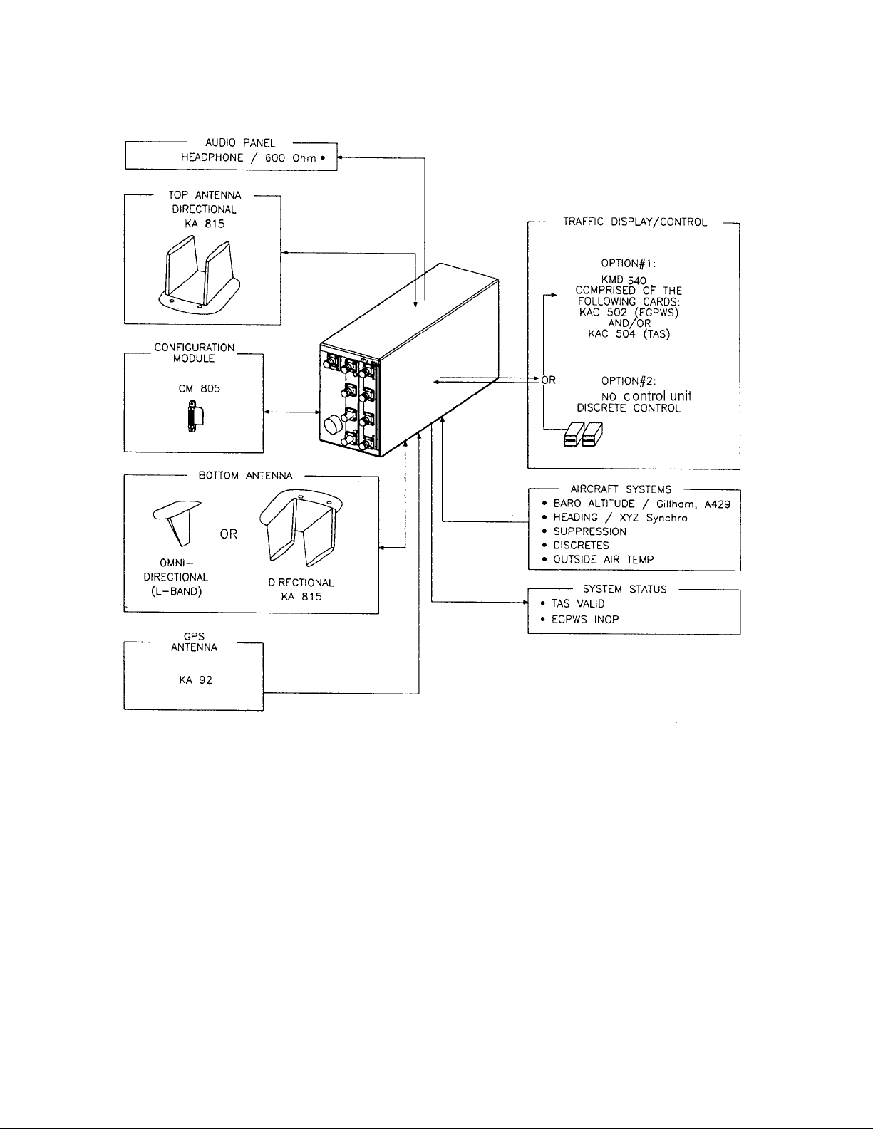
The KMH 880 Multi-Hazard Awareness System shall be composed of the KMH
820 (TAS/EGPWS Processor), a top mounted directional antenna (KA 815), a bottom mounted antenna (monopole or directional antenna which shall provide estimated bearing of target aircraft), a top mounted GPS antenna (KA 92), and a
Configuration Module (CM 805).
PRELIMINARY - SUBJECT TO CHANGE WITHOUT NOTICE
Rev 0, October/2000 10609I00.ZIPCDL Page1-3
Page 18

B
B KMH 880/KTA 870
BB
A Multifunctional Display Unit, KMD 540, shall provide control and display of traffic
(via the KAC 504 Traffic Card) and control and display of EGPWS data (via the
KAC 502 Adapter Card). Other displays that are compatible with ARINC 735A
may be used for traffic with this system. See Figure 1-1.
The KTA 870 Traffic Advisory System is similar to the KMH 880 except the KTA
810 Traffic Advisory Unit has only TAS and not EGPWS. The KTA 870 system
does not use a KA 92 GPS antenna. See Table 1-2 and Table 1-3 for a complete
description and part number listing for both systems.
KMH 880 SYSTEM PRIMARY LRUs
System Component LRU Manufacturer/
Model Designator
TA S/ G A E G P W S
Processor
Directional Antenna Bendix/King KA 815 TAS Directional Antenna 071-01599-0100
GPS Antenna Bendix/King KA 92 GPS Antenna 071-01553-0200
Configuration Module Bendix/King CM 805 Configuration Module 071-00112-0100
Control Panel/Display Bendix/King KMD 540 Multi-function Display 066-04035-0X01
Bendix/King KMH 820 Multi-Hazard Awareness
Bendix/King KAC 502 EGPWS Card 071-00158-0211
Bendix/King KAC 504 Traffic Card 071-00166-0411
LRU Description LRU Part Number
066-01175-0101
Processor
066-01175-2101
Table 1-2 KMH 880 LRUs
KTA 870 SYSTEM PRIMARY LRUs
System Component LRU Manufacturer/
Model Designator
LRU Description LRU Part Number
TAS Processor Bendix/King KTA 810 TAS Processor 066-01152-0101
Directional Antenna Bendix/King KA 815 TAS Directional
Antenna
Configuration Module Bendix/King CM 805 Configuration Module 071-00112-0100
Control Panel/Display Bendix/King KMD 540 Multi-function Display 066-04035-0X01
Bendix/King KAC 504 Traffic Card 071-00166-0411
071-01599-0100
Table 1-3 KTA 870 LRUs
PRELIMINARY - SUBJECT TO CHANGE WITHOUT NOTICE
Page1-4 10609I00.ZIPCDL Rev 0, October/2000
Page 19
B KMH 880/KTA 870
Figure 1-1 KMH 880/KTA 870 System
1.3.4 System Operation
A. EGPWS System
1. EGPWS Modes of Operation
a. TSO Mode
The EGPWS has provisions to allow the selection of alerting/warning curves
which comply with the requirements of TSO C151a class B or an alternate set
PRELIMINARY - SUBJECT TO CHANGE WITHOUT NOTICE
Rev 0, October/2000 10609I00.ZIPCDL Page1-5
of warning curves which are optimized for some General Aviation operations
which do not require compliance with TSO C151a-class B.
Page 20

B
B KMH 880/KTA 870
BB
This option is programmed into the EGPWS configuration module during system installation and thus remains specific to the aircraft. Once set up, any
Enhanced Ground Proximity Warning Computer installed in the aircraft will
access the configuration module and provide the appropriate mode of operation.
NOTE
All aircraft, which are required by Federal Aviation Regulations to have
Terrain Awareness and Warning System (TAWS) comply with TSO
C151a-class B, must be configured with the TSO curves. Additionally,
the alternate Audio Menu must be selected to meet the alert/warning
aural requirements of the TSO.
b. Non-TSO Mode
If this installation is intended to provide the operator with a non-required Terrain Awareness and Warning System to enhance safety of flight, it may be
appropriate to select the Non-TSO Mode of operation. As a general rule,
higher performance aircraft, especially ones flown primarily IFR and operating into larger airports may find the TSO curves most appropriate. Slower
performance aircraft operating primarily VFR and operating at low altitudes
AGL into small airports may find the Non-TSO curves better suit their operation. Any installation not required to comply with TSO C151a-class B may
select either the Basic Audio menu or the Alternate Audio menu.
The EGPWS may also be installed in aircraft that do not require FAA approved
TAWS Systems, and may be utilized with an optional set of alerting and warning
parameters that are designed especially for smaller piston aircraft and their normal flight characteristics.
c. GPS Sensor
The KMH 880 contains an embedded GPS-XPRESS Card sensor that produces validated navigational position data by continuous signal acquisition
and tracking of the navigational satellite network. The GPS Sensor receives
the C/A code signals transmitted by the satellite network on the L1 frequency
of 1575.42 MHz. The sensor has 8 signal processing channels allowing 8 satellites to be tracked simultaneously. At least 4 satellites must be in view of the
antenna for the sensor to operate. The GPS Sensor uses data in the satellites’ navigation messages to solve for latitude, longitude, altitude, horizontal
velocity, vertical velocity and current UTC.
PRELIMINARY - SUBJECT TO CHANGE WITHOUT NOTICE
Page1-6 10609I00.ZIPCDL Rev 0, October/2000
Page 21

B KMH 880/KTA 870
GPS Data can also be supplied via the ARINC 743, 743A and RS 232
(KLN94) interfaces.
A GPS Antenna Splitter could be used in liew of installing another antenna.
B. TAS System
1. TAS Modes of Operation
a. Setup Mode
The system shall be configured using an external PC via the Diagnostic
(RS 232) Interface. Reference the Appendices for the programming proce-
dures.
b. Standby Mode
When the Standby mode is selected, the TAS Processor shall disable
surveillance and tracking operations.
The Standby mode may be activated by any of the following: discrete
selection, self-test, aircraft on ground (configuration option), or system failure.
c. Functional Test Mode
When the Functional Test mode is selected, the unit shall be placed into the
Standby mode and the Functional Test portion of BITE shall be performed.
d. TAS Operation (Traffic Advisory) Mode
When the TAS Operation mode is selected, the TAS Processor shall perform
all the surveillance functions and shall provide for the generation of traffic
advisories . The information conveyed in the traffic advisories is intended to
assist the flight crew in sighting nearby traffic.
e. TAS Processor
The TAS Processor shall provide intruder surveillance and tracking, generating traffic advisories for both Altitude-Reporting and Non-Altitude-Reporting
intruders to display potential conflicts and advisories to the flight crew.
The TAS Processor shall track intruders under surveillance and analyze
range and range rate data, and altitude of the traffic to determine whether
that intruder represents a threat.
PRELIMINARY - SUBJECT TO CHANGE WITHOUT NOTICE
Rev 0, October/2000 10609I00.ZIPCDL Page1-7
Page 22

B
B KMH 880/KTA 870
BB
The TAS Processor shall also select "proximate traffic" and "other traffic"
intruders to be displayed on the basis of their altitude relative to own aircraft.
The "other traffic" intruders are those that do not qualify to be TA or proximate
traffic but are displayed.
NOTE
Optional (The TAS Processor may be controlled using discrete inputs).
C. Options
1. Display Option
TSO C151a-class B does not require a display for terrain data, however, if at
all possible, terrain data should be displayed for the aircraft operator. The terrain display greatly improves situational awareness. The EGPWS supports
numerous displays including traditional Radar displays as well as mode modern MFD’s.
Installations, which include a display, will also need to provide the EGPWS
with range data via ARINC 429 format.
2. Altitude Monitor Option
The EGPWS has the ability to monitor altitude sources and provide cautionary messages should an altitude source be suspected of being in error. This
feature compares barometric altitude with GPS altitude and generates a
“Check Altitude” message when an error is detected. This is a highly recommended option, which can alert a pilot to problems such as a stuck altimeter
or plugged static port. This option requires no additional hardware and is
enabled during the system installation by programming the configuration
module. This feature can provide both audio and display messages.
3. Outside Air Temperature (OAT) (Recommended)
The EGPWS supports an OAT probe for aircraft operated in cold environments. Very cold air temperatures cause an increase in the density of the air
mass and can result in barometric altimeter errors, both in sensitive altimeters/encoders and blind encoders. Aircraft normally operated in very cold climates can benefit from the addition of an OAT probe interfaced to the
EGPWS. If the aircraft is equipped with an Air Data Computer which outputs
Digital data with Corrected Altitude on an ARINC 429 port, this can be used
instead of an encoder and external OAT Probe. OAT is programmed into the
configuration module during system installation.
PRELIMINARY - SUBJECT TO CHANGE WITHOUT NOTICE
Page1-8 10609I00.ZIPCDL Rev 0, October/2000
Page 23

B KMH 880/KTA 870
1.4 TECHNICAL CHARACTERISTICS
KMH 820 w/o GPS MULTI-HAZARD AWARENESS UNIT
P/N 066-01175-0101
TSO COMPLIANCE:
PHYSICAL DIMENSIONS:
WEIGHT:
Installation Kit
POWER REQUIREMENTS:
See TSO Appendix E
See Figure 2-1
9.32 lbs.
050-03361-0000
Voltage Nominal: +28 Vdc
Range: +22 to +30 Vdc
Current Nominal: 1.3 ± 0.2 A
Max Operating 1.65 ± 0.2 A
Bootup: 3.3 ± 0.5 Α
Power 46 ± 2.3 Watts
Table 1-4 KMH 820 w/o GPS Multi-Hazard Awareness Unit Technical Specifications
KMH 820 w/ GPS MULTI-HAZARD AWARENESS UNIT
P/N 066-01175-2101
TSO COMPLIANCE:
PHYSICAL DIMENSIONS:
WEIGHT:
Installation Kit
POWER REQUIREMENTS:
PRELIMINARY - SUBJECT TO CHANGE WITHOUT NOTICE
Table 1-5 KMH 820 w/ GPS Multi-Hazard Awareness Unit Technical Specification
See TSO Appendix E
See Figure 2-1
9.68 lbs.
050-03361-0000
Voltage Nominal: +28 Vdc
Range: +22 to +30 Vdc
Current Nominal: 1.3 ± 0.2 A
Max Operating 1.65 ± 0.2 A
Bootup: 3.3 ± 0.5 Α
Power 46 ± 2.3 Watts
Rev 0, October/2000 10609I00.ZIPCDL Page1-9
Page 24

B
B KMH 880/KTA 870
BB
KTA 810 TRAFFIC ADVISORY UNIT
P/N 066-01152-0101
TSO COMPLIANCE:
PHYSICAL DIMENSIONS:
WEIGHT:
Installation Kit
POWER REQUIREMENTS:
Table 1-6 KTA 810 Traffic Advisory Unit Technical Specifications
See TSO Appendix E
See Figure 2-1
8.75 lbs
050-03361-0000
Voltage Nominal: +28 Vdc
Range: +22 to +30 Vdc
Current Nominal: 1.15 ± 0.2 A
Max Operating 1.45 ± 0.2 A
Bootup: 2.9 ± 0.5 Α
Power 41 ± 2.3 Watts
CM 805 CONFIGURATION MODULE
P/N 071-00112-0100
TSO COMPLIANCE:
PHYSICAL DIMENSIONS:
WEIGHT:
POWER REQUIREMENTS
See TSO Appendix E
See Figure 2-2
0.1 lbs.
5 Vdc from KMH 820/KTA 810.
Table 1-7 CM 805 Configuration Module Technical Specifications
PRELIMINARY - SUBJECT TO CHANGE WITHOUT NOTICE
Page1-10 10609I00.ZIPCDL Rev 0, October/2000
Page 25

B KMH 880/KTA 870
KA 815 TRAFFIC ANTENNA
P/N 071-01599-0100
TSO COMPLIANCE:
PHYSICAL DIMENSIONS:
WEIGHT:
Installation Kit
MOUNTING:
POWER REQUIREMENTS
Table 1-8 KA 815 Traffic Antenna Technical Specifications
See TSO Appendix E
See Figure 2-3
0.95 lbs.
050-03622-0000
See Figure 2-4 and 2-5
None
KA 92 GPS ANTENNA
P/N 071-01553-0200
TSO COMPLIANCE:
PHYSICAL DIMENSIONS:
WEIGHT:
Installation Kit
MOUNTING:
POWER REQUIREMENTS
See TSO Appendix E
See Figure 2-6
0.27 lbs.
050-03318-0000
See Figure 2-6
5v supplied by the GPS receiver.
Table 1-9 KA 92 GPS Antenna Technical Specifications
PRELIMINARY - SUBJECT TO CHANGE WITHOUT NOTICE
Rev 0, October/2000 10609I00.ZIPCDL Page1-11
Page 26

B
B KMH 880/KTA 870
BB
1.5 UNIT AND ACCESSORIES SUPPLIED
1.5.1 TAS Processor Unit
The TAS Processor will provide intruder surveillance and tracking, generating traf-
fic advisories for both Altitude-Reporting and Non-Altitude-Reporting intruders to
display potential conflicts and advisories to the flight crew.
The TAS Processor will track intruders under surveillance and analyze range and
range rate data, and altitude of the traffic to determine whether that intruder represents a threat.
SYSTEM
COMPONENT
TA S/ G A E G P W S
Processor
TA S
Processor
MANUFACTURER/
MODEL DESIGNER
Bendix/King
KMH 820
Bendix/King KTA
810
Table 1-10 KMH 820/KTA 810 Processor Units
1.5.2 Configuration Module
The Configuration Module contains two EEPROMs, one for the TAS Processor
and one for the EGPWS.
The Configuration Module will be remotely mounted in the airframe. It will be
mapped with the Configuration at the installation of the system. An external PC
program will be available to the installer to initialize/program the configuration
module. Reference this Install Manual, Section IV for the programming procedures. A system failure will be annunciated if the configuration module is not programmed, not compatable with the current TAS processor software or if the CRC
read from the module is incorrect.
DESCRIPTION
Multi-Hazard
Awareness Processor
TA S
Processor
PA R T N U M B E R
066-011750101
066-011752101
066-011520101
TSO
COMPLIANCE
TSO C147
TSO C151a
TSO C147
SYSTEM
COMPONENT
Configuration
Module
MANUFACTURER/
MODEL DESIGNER
Bendix/King
CM 805
DESCRIPTION PART NUMBER
Configuration Module 200-00112-0100 TSO C147
TSO
COMPLIANCE
TSO C151a
Table 1-11 CM 805 Configuration Module
PRELIMINARY - SUBJECT TO CHANGE WITHOUT NOTICE
Page1-12 10609I00.ZIPCDL Rev 0, October/2000
Page 27

B KMH 880/KTA 870
1.5.3 Antennas
Full bearing coverage will be achieved by the use of a top and bottom directional
antenna system. The TAS Processor will also be capable of supporting a top
directional and bottom monopole antenna configuration. In the latter configuration,
only intruders being tracked via the top directional antenna will have bearing information.
The antennas will be vertically polarized and cover 360 degrees in azimuth and at
least -10 to +20 degrees in elevation.
SYSTEM
COMPONENT
Directional
Antenna
GPS Antenna Bendix/King
Omni-Directional
Antenna
MANUFACTURER/
MODEL DESIGNER
Bendix/King
KA 815
KA 92
Dorne and Margolin L-Band Antenna DM NI50-2-2* TSO C66a
DESCRIPTION PART NUMBER
TAS Directional
Antenna
GPS Antenna 071-01553-0200 TSO C129
071-01599-0100 TSO C147
COMPLIANCE
TSO C74
Table 1-12 KA 815/KA 92 Antennas
* This antenna has not been tested for direct effects of lightning and the installer
must determine the suitability of the antenna for the specific installation.
CABLE TYPES AND PERMISSABLE GPS CABLE RUN LENGTHS
(8dB allowable loss, including splitter.)
CABLE TYPE
CABLE RUN LENGTH
(W/O Splitter)
TSO
* R/G 142B/U
P/N 024-00002-0000
* R/G 400/U
P/N 024-00051-0060
* These cables use R/G 142/400 style connectors.
Note:
When using Non-KPN or Non-standard P/N cables, connectors etc., the installer has the responsibility of
proving airworthiness.
Up to 46 ft.
Up to 46 ft.
Table 1-13 GPS Cable Run Lengths
PRELIMINARY - SUBJECT TO CHANGE WITHOUT NOTICE
Rev 0, October/2000 10609I00.ZIPCDL Page1-13
Page 28

B
B KMH 880/KTA 870
BB
1.6 INSTALLATION ACCESSORIES SUPPLIED
1.6.1 KMH 820/KTA 810 Installation Kit
SYMBOL PART NUMBER DESCRIPTION [UOM] -0000
200-09894-0000 Rack, KMH 820/ KTA 810 [EA] 1
J10 D38999/26FJ35SN 128 Pin I/O Connector [EA] 1
M85049/38-25N Strain Relief for 128 Pin I/O Connector [EA] 1
J4,J8 030-00005-0002 TAS Antenna Ports, BNC Connectors [EA] 2
J1-J3,
J5-J7, J9
030-01171-0000 Conn Sub-D HSG 9S (Female Pins) [EA] 2
030-00134-0000 Connector, TNC [EA] 7
071-00112-0100 CM 805 Configuration Module [EA] 1
010-00135-0000 Terminals [EA] 2
010-00068-0026 Terminals [EA] 8
150-00072-0000 Solder Sleeve [EA] 8
030-01157-0011 Socket Contact [EA] 6
030-01451-0000 Socket Contact 22 ga [EA] 15
030-01464-0000 9 Pin Plastic Hood [EA] 2
030-01428-0001 EMI Hood W/ Lock 15 Pin High Density [EA] 1
030-03447-0001 High Density 15 Pin Female DSub [EA] 1
155-06060-0000 KMH 820/KTA 810 Installation Drawing REF
Table 1-14 KMH 820/KTA 810 Installation Kit P/N 050-03361-0000
PRELIMINARY - SUBJECT TO CHANGE WITHOUT NOTICE
Page1-14 10609I00.ZIPCDL Rev 0, October/2000
Page 29

B KMH 880/KTA 870
1.6.2 Antenna Installation Kits
SYMBOL PART NUMBER DESCRIPTION [UOM] -0000
071-01599-0100 KA 815 Antenna [EA] 1
M39012/30-0101 Connector, TNC Rt Angle [EA] 4
MS29513-148 KA 815 O-Ring [EA] 1
MS24693-C54 Screw PHP 8-32x.875 [EA] 4
155-06059-0000 KA 815 Installation Drawing REF
Table 1-15 KA 815 Installation Kit P/N 050-03622-0000
SYMBOL PART NUMBER DESCRIPTION [UOM] -0000
030-00134-0001 Connector, TNC Rt Angle [EA] 1
047-10735-0002 Antenna DBLR Complete [EA] 1
089-05909-0012 Screw PHP 8-32x3/4 [EA] 4
187-01831-0000 Antenna Gasket [EA] 1
155-06019-0000 KA 92 INstallation Drawing REF
Table 1-16 KA 92 Installation Kit P/N 050-03318-0000
1.6.3 Databases
PART NUMBER DESCRIPTION [UOM]
071- 00167-0101 America’s Database [EA]
071-00167-0102 Atlantic Database [EA]
071-00167-0103 Pacific Database [EA]
Table 1-17 KMH 880/KTA 870 Databases
PRELIMINARY - SUBJECT TO CHANGE WITHOUT NOTICE
Rev 0, October/2000 10609I00.ZIPCDL Page1-15
Page 30

B
B KMH 880/KTA 870
BB
1.7 ACCESSORIES REQUIRED BUT NOT SUPPLIED
1.7.1 Temperature Probe
The EGPWS is capable of interfacing directly to a standard 500 ohm temperature
probe for aircraft operated in cold environments. Very cold air temperatures cause
an increase in the density of the air mass and can result in barometric altimeter
errors, both in sensitive altimeters/encoders and blind encoders. Aircraft normally
operated in very cold climates can benefit from the addition of an OAT probe interfaced to the EGPWS
SYMBOL PART NUMBER DESCRIPTION [UOM] -0001
137-00042-0001 OAT Probe [EA] 1
MS3106E12S-3S OAT Probe Connector [EA] 1
090-01034-0001 OAT Probe Mounting Kit [EA] 1
010-00068-0016 Crimp Terminal [EA] 1
Table 1-18 Temperature Probe P/N 050-03610-0002
NOTE
The EGPWS Processor does not require a Temperature Probe input if a Digital Air
Data Computer, with an OAT Label present on the bus, is available as an interface.
1.7.2 GPS Antenna Splitter
To have the flexibility of using an existing KA 92 GPS Antenna, Honeywell offers a
splitter that will greatly simplify the installation procedure. One of the split ports is
DC blocked from the common port so that equipment voltage regulators do not
conflict.
SYMBOL PART NUMBER DESCRIPTION [UOM] QTY
050-03610-0003 GPS Antenna Splitter Kit [EA] 1
030-00134-0000 TNC Connector Straight [EA] 3
030-00134-0001 TNC Connector Rt Angle [EA] 1
Table 1-19 GPS Antenna Splitter P/N 071-01600-0001
PRELIMINARY - SUBJECT TO CHANGE WITHOUT NOTICE
Page1-16 10609I00.ZIPCDL Rev 0, October/2000
Page 31

B KMH 880/KTA 870
1.7.3 Miscellaneous
SYMBOL PART NUMBER DESCRIPTION [UOM] QTY
050-03610-0000 Basic Annunciator Kit [EA] 1
050-03610-0001 Terrain Switching Kit [EA] 1
Table 1-20 Miscellaneous Accessories
NOTE:
Specification Drawing 031-00810-01 defines all of the sub-assembly parts
and spacers to cover different panel thicknesses (Sheet 2). Artwork definitions
for associated items are also covered (Sheet 3).
1.7.4 CABLE AND WIRE
SYMBOL PART NUMBER DESCRIPTION [UOM] QTY
M17/158-RG400 Coaxial Cable [FT] AR
MIL-W-22759/16 or Equivalent. Wire [FT] AR
M17/176-00002 Shielded Wire [FT] AR
MIL-C-27500 or Equivalent. Shielded Wire [FT] AR
Table 1-21 Cable and Wire
1.8 LICENSE REQUIREMENTS
There are no license requirements for the KMH 880/KTA 870 Multi-Hazard/Traffic
Advisory System.
1.9 INSTRUCTIONS FOR CONTINUED AIRWORTHINESS
FAR Part 23.1529, 25.1529, 27.1529, AND 29.1529 Instructions for Continued
Airworthiness is met per the following Instructions:
Design and manufacture of the equipment will provide for installation so as not to
impair the airworthiness of the aircraft.
PRELIMINARY - SUBJECT TO CHANGE WITHOUT NOTICE
Rev 0, October/2000 10609I00.ZIPCDL Page1-17
Page 32

B
B KMH 880/KTA 870
BB
1.9.1 KMH 820/KTA 810 Unit
If the unit should require maintenance, remove the unit and have it repaired by an
appropriately rated Honeywell approved Instrument Service Center. If the aircraft
is to fly with the KMH 820/KTA 810 removed, secure the connector(s) as necessary and placard the aircraft accordingly. After re-installation of the unit, accomplish the appropriate Post Installation Checkout in Section IV.
During each annual or 100 hour inspection of the aircraft, perform a Level 2 Self
Test of the KMH 820/KTA 810 as defined in the Post Installation Checkout in Section IV.
1.9.2 Annunciators/Relays
If an annunciator bulb needs replacement, use a bulb with with the same type and
voltage rating as originally installed. If a relay malfunctions, replace it with an airworthy relay having the same part number. If a combination annunciator/relay unit
is used, e.g. MD41-1208/1308, remove the unit and have it repaired by a factoryrated service center. If the aircraft is to fly with a relay or annunciator removed,
secure the connector(s) as necessary and placard the aircraft accordingly. After
re-installation of the unit, accomplish the appropriate Post Installation Checkout in
Section IV.
1.9.3 GPS Antenna
If the GPS Antenna should fail, replace it with an airworthy antenna having the
same part number. Verify good electrical bonding surfaces before installing the
antenna. Ensure that antenna radome is clean and not covered with paint. After
re-installation of the antenna, accomplish the appropriate Post Installation Checkout in Section IV.
1.9.4 GPS Antenna Splitter
If the GPS Antenna Splitter should fail, replace it with an airworthy antenna splitter
having the same part number. The signal loss between the GPS Antenna and the
GPS Receiver cannot exceed 8 dB. After re-installation of the GPS Antenna Splitter, accomplish the appropriate Post Installation Checkout in Section IV.
1.9.5 Temperature Probe
If the KMH 820/KTA 810 Self Test indicates a failure of the temperature probe,
replace the temperature probe with an airworthy temperature probe having the
same part number. after installation of the temperature probe, accomplish the
appropriate Post Installation Checkout in Section IV.
PRELIMINARY - SUBJECT TO CHANGE WITHOUT NOTICE
Page1-18 10609I00.ZIPCDL Rev 0, October/2000
Page 33

B KMH 880/KTA 870
1.9.6 Wires and Coax Cables
During ON-condition or regularly scheduled maintenance, inspect the wires and
coax cables following the guidelines listed in AC 43.13-1B Chapter 11 as necessary.
1.9.7 Terrain Data Base Updates
To order database updates contact Honeywell International Inc., Navigation Services:
Honeywell International Inc.
Aerospace Electronic Systems
One Technology Center
23500 West 105th Street
Olathe, Kansas 66061 USA
Attn: Navigation Services MS 66
Phone:(800) 247-0230 within the United States or Canada
(913) 712-3145 outside of the United States or Canada
FAX: (913) 712-3904
e-mail:nav.database@honeywell.com
PRELIMINARY - SUBJECT TO CHANGE WITHOUT NOTICE
Rev 0, October/2000 10609I00.ZIPCDL Page1-19
Page 34

B KMH 880/KTA 870
THIS PAGE IS RESERVED
PRELIMINARY - SUBJECT TO CHANGE WITHOUT NOTICE
Rev 0, October/2000 10609I00.ZIPCDL Page1-20
Page 35

B
B KMH 880/KTA 870
BB
SECTION II
INSTALLATION
2.0 INTRODUCTION .............................................................................. 2-1
2.1 UNPACKING AND INSPECTING EQUIPMENT .............................. 2-1
2.2 EQUIPMENT INSTALLATION .......................................................... 2-1
2.2.1 General ............................................................................................. 2-1
2.2.2 Avionics Cooling Requirements ........................................................ 2-2
2.2.3 Processor Installation ....................................................................... 2-2
2.2.3.1 Cooling Considerations ..................................................................... 2-2
2.2.3.2 Installation Considerations ................................................................ 2-2
2.2.3.3 Installation Procedure ....................................................................... 2-4
2.2.4 Configuration Module Installation ...................................................... 2-9
2.2.4.1 Cooling Considerations ..................................................................... 2-9
2.2.4.2 Installation Considerations ................................................................ 2-9
2.2.4.3 Installation Procedure ....................................................................... 2-9
2.2.5 DIRECTIONAL ANTENNA INSTALLATION ..................................... 2-13
2.2.5.1 KA 815 Antenna Installation Considerations .................................... 2-13
2.2.6 GPS ANTENNA INSTALLATION ..................................................... 2-17
2.2.6.1 KA 92 Antenna Installation Considerations (KMH 820 EGPWS only) 2-17
2.2.6.2 Installation Procedure ....................................................................... 2-17
2.2.7 TAS Coaxial Cable Fabrication.......................................................... 2-26
2.2.8 GPS Coaxial Cable Fabrication......................................................... 2-27
LIST OF ILLUSTRATIONS
Figure 2-1 KMH 820/KTA 810 Installation Drawing....................................... 2-5
Figure 2-2 Configuration Module Installation Drawing................................... 2-11
Figure 2-3 KA 815 Antenna Outline Drawing ................................................ 2-15
Figure 2-4 KA 815 Antenna Installation Drawing........................................... 2-19
Figure 2-5 KA 815 Doubler Plate Drawing..................................................... 2-21
Figure 2-6 KA 92 Outline and Mounting Drawing ......................................... 2-23
Figure 2-7 GPS Antenna Splitter ................................................................... 2-25
Figure 2-8 Coax Cable Treatment ................................................................. 2-28
Figure 2-9 Standard Coax Cable................................................................... 2-28
Figure 2-10 Bulkhead/In-Line Connection Coax Cable ................................... 2-28
Figure 2-11 TNC Antenna Coax/Connector Assembly.................................... 2-29
Figure 2-12 TNC Antenna Coax/Connector Assembly.................................... 2-30
LIST OF TABLES
Table 2-1 Signal Losses............................................................................... 2-27
PRELIMINARY - SUBJECT TO CHANGE WITHOUT NOTICE
Rev 0, October/2000 10609I00.ZIPCDL TOC 2-i
Page 36

B
B KMH 880/KTA 870
BB
THIS PAGE IS RESERVED
PRELIMINARY - SUBJECT TO CHANGE WITHOUT NOTICE
TOC 2-ii 10609I00.ZIPCDL Rev 0, October/2000
Page 37

B
B KMH 880/KTA 870
BB
SECTION II
INSTALLATION
2.0 INTRODUCTION
This section contains suggestions and factors to consider before installing the KMH 880/
KTA 870 System. Close adherence to these suggestions will assure satisfactory performance from the equipment.
NOTE
The conditions and tests performed on the system components are minimum performance standards. It is the responsibility of those desiring to
install the KMH 880/KTA 870 either on or within a specific type or class of
aircraft to determine that the aircraft installation conditions are within the
TSO standards. The KMH 880/KTA 870 may be installed only if further
evaluation by the applicant documents an acceptable installation and is
approved by the administrator.
2.1 UNPACKING AND INSPECTING EQUIPMENT
Exercise extreme caution when unpacking equipment. Perform a visual inspection of the
unit for evidence of damage incurred during shipment. If a damage claim must be filed,
save the shipping container and all the packing materials to substantiate your claim. The
claim should be filed as soon as possible. The shipping container and all packing material should be retained in the event that storage or re-shipment of the equipment is necessary.
2.2 EQUIPMENT INSTALLATION
2.2.1 General
The following paragraphs contain information pertaining to the installation of the
KMH 880/KTA 870 System, including instructions concerning location and mounting of the antennas.
The equipment should be installed in the aircraft in a manner consistent with
acceptable workmanship and engineering practices, and in accordance with the
instructions set forth in this publication. To ensure the system has been properly
and safely installed in the aircraft, the installer should make a thorough visual
inspection and conduct an overall operational check of the system, on the ground,
prior to flight.
PRELIMINARY - SUBJECT TO CHANGE WITHOUT NOTICE
Rev 0, October/2000 10609I00.ZIPCDL Page 2-1
Page 38

B
B KMH 880/KTA 870
BB
CAUTION
AFTER INSTALLATION OF THE CABLING AND BEFORE
INSTALLATION OF THE EQUIPMENT, A CHECK SHOULD
BE MADE WITH THE AIRCRAFT PRIMARY POWER SUPPLIED TO THE MOUNTING CONNECTOR, TO ENSURE
THAT POWER IS APPLIED ONLY TO THE PINS SPECFIED
IN THE INTERWIRING DIAGRAMS IN SECTION III.
The KMH 880/KTA 870 System installation will conform to standards designated
by the customer, installing agency, and existing conditions as to the unit location
and type of installation. However, the following suggestions should be carefully
considered before installing your system.
2.2.2 Avionics Cooling Requirements
The most important contribution to improved reliability of all avionics equipment is
to limit the maximum operating temperature of the individual unit, whether panel
mounted or remote mounted. While modern circuit designs consume less total
energy, the heat dissipated per unit volume (Watts/cubic inch) remains much the
same due to contemporary high density packaging techniques. While each individual unit may not require forced air cooling, the combined heat generated by
several units operating in a typical panel or rack, can significantly degrade the reliability of the equipment. Consequently, the importance of providing force air cooling to avionics equipment mounted in either a panel or rack, is essential to the life
span of the equipment. Adequate provisions for cooling should be incorporated
during the installation.
2.2.3 Processor Installation
2.2.3.1 Cooling Considerations
The KMH 820/KTA 810 requires no external forced air cooling.
2.2.3.2 Installation Considerations
Consideration should be given to the following items affected by the choice of
installation location within the aircraft:
A. Environmental Considerations
PRELIMINARY - SUBJECT TO CHANGE WITHOUT NOTICE
Page 2-2 10609I00.ZIPCDL Rev 0, October/2000
B. Ease of Interface to aircraft systems
Page 39

B
B KMH 880/KTA 870
BB
C. GPS Antenna location and coaxial cable length
D. Ability to extract and insert new terrain/obstacle Data Bases supplied on a
CompactFlash Card.
If possible, install the KMH 820/KTA 810 in a dry, temperature-controlled area
such as within the passenger compartment of the aircraft. Standard avionics bays
are accepable as well.
If possible, the KMH 820/ KTA 810 should NOT be located in close proximity to
equipment which produce considerable heat.
Locations, which require disassembly of the aircraft to gain access, are less desir-
able.
Any location that is exposed to moisture and/or temperature extremes should be
avoided.
Select a mounting location that allows sufficient clearance at the front of the unit
for connectors and cables.
Do not bundle data lines or antenna cable with any power cables.
No more than 8.0dB signal loss is allowed in the GPS antenna cable run, including the antenna splitter, (if used). Refer to Note 5 on the Antenna Interface Drawing and Table 1-13 in Section 1 for information on cable types and lengths.
Mount the unit to provide good electrical bonding to airframe ground. Lightning
strike protection and RF susceptibility and emission characteristics depend on
good electrical grounding of the unit and cable shield returns.
Refer to Figures 2-11 and 2-12 for TNC connector assembly guidelines.
NOTE
The KMH 820/KTA 810 will need to interface to the aircraft audio system, aircraft DC power, panel mounted warning lamps and switches, a
source of barometric altitude (usually an encoding altimeter or blind
encoder), a GPS antenna and a panel mounted display.
PRELIMINARY - SUBJECT TO CHANGE WITHOUT NOTICE
Rev 0, October/2000 10609I00.ZIPCDL Page 2-3
Page 40

B
B KMH 880/KTA 870
BB
If possible, clearance to the top of the KMH 820 should be provided to facilitate
removal and installation of the terrain database CompactFlash card. The terrain
database card is removed and installed with power NOT applied to the system.
The KMH 820 may be removed from the aircraft to extract and install database
cards if the mounting location does not provide enough clearance.
Updating the Terrain DataBase is accomplished by:
Moving the aluminum cover over the CompactFlash card out of the way.
Pressing the flash card ejector button located within the unit.
Removing the old flash card.
Inserting the new flash card and replacing the cover.
If possible, mount the KMH 820 such that the above can be accomplished without
requiring disassembly of the aircraft or removal of the KMH 820.
The KMH 820 drives three lamps and accepts input from two switches. The lamps
should be identified as:
FUNCTION COLOR LEGEND
Not Available Amber Terrain N/A or Terr N/A
Caution Amber Terrain
Warning Red Terrain
The RED Warning lamp must be located in the pilot’s primary field of view.
The EGPWS provides a single 600 ohm audio output which should be connected
to a un-switched/un-muted auxiliary audio input on the aircraft’s audio control
panel. The audio output power level is set by programming the configuration module.
2.2.3.3 Installation Procedure
A. Slide the unit into the rack and secure it.
B. Attach the harness to the front mating connector of the unit.
PRELIMINARY - SUBJECT TO CHANGE WITHOUT NOTICE
Page 2-4 10609I00.ZIPCDL Rev 0, October/2000
C. Attach coax cables J1 thru J10 to the front of the unit.
Page 41

B
B
BB
KMH 880/KTA 870
Figure 2-1 KMH 820/KTA 810 Installation Drawing
Dwg. No. 300-05639-0000 R-0 (Sheet 1 of 2)
PRELIMINARY - SUBJECT TO CHANGE WITHOUT NOTICE
Rev 0, October/2000 10609I00.ZIPCDL Page 2-5
Page 42

B
B
BB
KMH 880/KTA 870
THIS PAGE IS RESERVED
PRELIMINARY - SUBJECT TO CHANGE WITHOUT NOTICE
Page 2-6 10609I00.ZIPCDL Rev 0, October/2000
Page 43

B
B
BB
KMH 880/KTA 870
Figure 2-1 KMH 820/KTA 810 Installation Drawing
Dwg. No. 300-05639-0000 R0 (Sheet 2 of 2)
PRELIMINARY - SUBJECT TO CHANGE WITHOUT NOTICE
Rev 0, October/2000 10609I00.ZIPCDL Page 2-7
Page 44

B
B
BB
KMH 880/KTA 870
THIS PAGE IS RESERVED
PRELIMINARY - SUBJECT TO CHANGE WITHOUT NOTICE
Page 2-8 10609I00.ZIPCDL Rev 0, October/2000
Page 45

B
B KMH 880/KTA 870
BB
2.2.4 Configuration Module Installation
System configuration is defined via a Configuration Module which contains the aircraft
interface and functionality definitions specific to the installed aircraft.
2.2.4.1 Cooling Considerations
A. Make sure that the unit is installed in a location where the ambient tem-
peratures are -67°F to +158°F (-55°C to +70°C).
2.2.4.2 Installation Considerations
A. The Configuration Module must be mounted to the airframe within maxi-
mum cable/harness length of 2 feet. Make sure to leave adequate space
to mount the Configuration Module when installing the Processor Unit.
2.2.4.3 Installation Procedure
A. Install the Configuration Module into the airframe. Refer to figure 2- 2 .
B. Tighten the mounting screws to secure the Configuration Module.
PRELIMINARY - SUBJECT TO CHANGE WITHOUT NOTICE
Rev 0, October/2000 10609I00.ZIPCDL Page 2-9
Page 46

B
B KMH 880/KTA 870
BB
THIS PAGE IS RESERVED
PRELIMINARY - SUBJECT TO CHANGE WITHOUT NOTICE
Page 2-10 10609I00.ZIPCDL Rev 0, October/2000
Page 47

B
B
BB
KMH 880/KTA 870
Figure 2-2 Configuration Module Installation Drawing
Dwg. No. 300-06161-0000 R-0
PRELIMINARY - SUBJECT TO CHANGE WITHOUT NOTICE
Rev 0, October/2000 10609I00.ZIPCDL Page 2-11
Page 48

B
B
BB
KMH 880/KTA 870
THIS PAGE IS RESERVED
PRELIMINARY - SUBJECT TO CHANGE WITHOUT NOTICE
Page 2-12 10609I00.ZIPCDL Rev 0, October/2000
Page 49

B
B KMH 880/KTA 870
BB
2.2.5 DIRECTIONAL ANTENNA INSTALLATION
2.2.5.1 KA 815 Antenna Installation Considerations
A. Antenna Location
NOTE
The following antenna location procedure is provided for guidance purposes and to outline a method of achieving certifiable system performance.
The KMH 880/KTA 870 System uses a top-mounted directional antenna and
either a bottom-mounted directional or an L-band omni-directional antenna.
Refer to directional antenna outline drawings in Figure 2-3. Mounting the
directional antenna MUST include the appropriate doubler plate.The installing agency is required to fabricate the doubler plate for the antenna installations.
NOTE
The L-band omni-directional has not been tested for the direct effects of lightning
and the installer (TC or STC applicant) must determine the suitability of the
antenna for the specific installation.
NOTE
KMH 880/KTA 870 Systems REQUIRE that the antenna installation
guidelines be followed. Adherence to these guidelines will assure that critical specifications are considered. Optimum bearing accuracy can be
achieved by following these directions.
Antenna locations should be chosen so that both antennas appear to be at
the same range and bearing from the intruder.
The centerline of the top and bottom-mounted TAS Antenna should be
located as close as possible to the aircraft centerline.
The top directional TAS Antenna should be the most forward antenna and as
PRELIMINARY - SUBJECT TO CHANGE WITHOUT NOTICE
Rev 0, October/2000 10609I00.ZIPCDL Page 2-13
far forward on the constant radius portion on the fuselage as possible.
Page 50

B
B KMH 880/KTA 870
BB
Obstructions and ground plane discontinuities, such as door hatches, cowlings and unriveted airframe skin overlaps must be 18 inches from the nearest edge of the TAS Antenna. Other antennas, particularly high profile and Lband transponder antennas, cannot be located in front of or within 30 inches
(edge to edge) of the top mounted TAS directional antenna. This will ensure
a minimum of 20 dB of isolation at 1090 MHz, while minimizing far-field path
distortion in the forward quadrants.
B. Mount the antenna on the aircraft skin which is horizontal during enroute
flight. Antenna baseplate must be level within + or - 5° in longitudinal and lateral axes when the aircraft is in level flight. See Figure 2-4.
C. The antenna must be mounted on a nearly flat surface such that the antenna
contacts the bare metal skin all around the perimeter without gaps when normal mounting screw torque is applied.
NOTE
Aircraft with fixed landing gear must be equipped with a bottom mono-
pole antenna. Furthermore, the landing gear discrete must be strapped
to the retracted position. The bearing from a bottom directional is invalidated when landing gear is extended, so it would always be invalidated
on a fixed-gear aircraft. (Therefore, there would be no use for a directional
antenna.)
PRELIMINARY - SUBJECT TO CHANGE WITHOUT NOTICE
Page 2-14 10609I00.ZIPCDL Rev 0, October/2000
Page 51

B
B KMH 880/KTA 870
BB
Figure 2-3 KA 815 Antenna Outline Drawing
PRELIMINARY - SUBJECT TO CHANGE WITHOUT NOTICE
Rev 0, October/2000 10609I00.ZIPCDL Page 2-15
Page 52

B
B KMH 880/KTA 870
BB
THIS PAGE IS RESERVED
PRELIMINARY - SUBJECT TO CHANGE WITHOUT NOTICE
Page 2-16 10609I00.ZIPCDL Rev 0, October/2000
Page 53

B
B KMH 880/KTA 870
BB
2.2.6 GPS ANTENNA INSTALLATION
2.2.6.1 KA 92 Antenna Installation Considerations (KMH 820 P/N 066-011752101 only)
A. The KA 92 GPS Antenna should be mounted on top of the fuselage near the
cockpit and in the centerline of the aircraft. Avoid mounting the antenna near
any projections, and the tail of the aircraft, where shadows could occur. It is
recommended that there be a separation of at least 3 feet between the GPS
antenna and any VHF Comm, HF Comm, etc. on the aircraft. A minimum of 3
feet from any satcomm antenna should also be observed. Refer to Figure 2-
6.
B. Mount the GPS antenna on the aircraft skin which is horizontal during
enroute flight. Antenna baseplate must be level within + or - 5° in the longitudinal and lateral axes when the aircraft is in level flight.
2.2.6.2 Installation Procedure
A. Make sure the antenna is well bonded to the aircraft skin.
B. Make sure the antenna is sealed to the aircraft to prevent corrosion from
forming between the skin of the aircraft and the antenna.
C. Install the optional GPS Antenna Splitter, if aircraft is already equipped with a
GPS antenna.
D. Make sure the antenna cable is connected to the antenna, splitter and unit
prior to system checkout.
E. Perform system checkout using instructions in Section 4.3.
PRELIMINARY - SUBJECT TO CHANGE WITHOUT NOTICE
Rev 0, October/2000 10609I00.ZIPCDL Page 2-17
Page 54

B
B KMH 880/KTA 870
BB
THIS PAGE IS RESERVED
PRELIMINARY - SUBJECT TO CHANGE WITHOUT NOTICE
Page 2-18 10609I00.ZIPCDL Rev 0, October/2000
Page 55

B
B
BB
KMH 880/KTA 870
Figure 2-4 KA 815 Installation and Mounting Drawing
Dwg No. 155-06059-0000
Rev 0, October/2000 10609I00.ZIPCDL Page 2-19
PRELIMINARY - SUBJECT TO CHANGE WITHOUT NOTICE
Page 56

B
B
BB
KMH 880/KTA 870
THIS PAGE IS RESERVED
PRELIMINARY - SUBJECT TO CHANGE WITHOUT NOTICE
Page 2-20 10609I00.ZIPCDL Rev 0, October/2000
Page 57

B
B
BB
KMH 880/KTA 870
Figure 2-5 KA 815 Doubler Plate
Rev 0, October/2000 10609I00.ZIPCDL Page 2-21
PRELIMINARY - SUBJECT TO CHANGE WITHOUT NOTICE
Page 58

B
B
BB
KMH 880/KTA 870
THIS PAGE IS RESERVED
PRELIMINARY - SUBJECT TO CHANGE WITHOUT NOTICE
Page 2-22 10609I00.ZIPCDL Rev 0, October/2000
Page 59

B
B
BB
KMH 880/KTA 870
Figure 2-6 KA 92 Outline and Mounting Drawing
Dwg. No. 155-06019-0000 R-AA
Rev 0, October/2000 10609I00.ZIPCDL Page 2-23
PRELIMINARY - SUBJECT TO CHANGE WITHOUT NOTICE
Page 60

B
B
BB
KMH 880/KTA 870
THIS PAGE IS RESERVED
PRELIMINARY - SUBJECT TO CHANGE WITHOUT NOTICE
Page 2-24 10609I00.ZIPCDL Rev 0, October/2000
Page 61

B KMH 880/KTA 870
Figure 2-7 GPS Antenna Splitter
Dwg. No. 071-01600-0001
PRELIMINARY - SUBJECT TO CHANGE WITHOUT NOTICE
Rev 0, October/2000 10609I00.ZIPCDL Page 2-25
Page 62

B KMH 880/KTA 870
2.2.7 TAS Coaxial Cable Fabrication
The TAS cables must have an attenuation of 2.0 ± 1.0 dB within the frequency band of
1030-1090 MHZ. To ensure proper phase matching, each of the four cables of a set must
be of the same type. The lengths in each set of four must be within 2.0” of each other.
Color bands on the cable ends to match the antenna color bands is suggested as an aid
to hook up. Cables can be fabricated or purchased from a cable vendor.
NOTE
The nominal length of each set of four cables should be recorded for the
particular installation in the event a cable should require replacement. If
rework is required, a cable may be cut a maximum of 6”.
The following defines the characteristics of the 50 ohm coaxial cable types that can be
used with the KA 815 Antenna. Connectors are also defined. All lengths are defined as
end to end. Any in-line or bulkhead penetrations must be evaluated separately. It is recommended that the installer purchase prefabricated cable assemblies when using in-line
or bulkhead disconnects. Prefabricated cables can be purchased from Pic Wire & Cable
or ECS. These vendors have expertise in providing the aviation industry reliable cable
assemblies that meet the requirements for the various collision avoidance systems. It is
the installing agency’s responsibility to show airworthiness of the fabricated cable assem-
blies.
When determining cable type and length make the following assumptions.
A. Attenuation of each straight TNC male connector is 0.06 dB @ 1GHz
(using a 030-00134-0000 RF Connector)
B. Attenuation of each right angle TNC male connector is 0.07 dB @ 1 GHz
(using a 030-00134-0001 RF Connector)
C. Attenuation of each TNC female panel mount connector is 0.06 dB @
1 GHZ (using a 030-00101-0002 RF Connector)
D. Attenuation of M17/128-RG 400 Coaxial Cable is 0.13 dB/ft @ 1 GHz
Using the above information, a RG 400 cable with a right angle TNC (antenna end) and a
straight TNC (KMH/KTA end) must be no longer than 22 feet long as measured from end
to end. If longer length is required, then a lower loss cable with appropriate connectors
must be selected. Reference the diagram below.
PRELIMINARY - SUBJECT TO CHANGE WITHOUT NOTICE
Page 2-26 10609I00.ZIPCDL Rev 0, October/2000
Page 63

B KMH 880/KTA 870
2.2.8 GPS Coaxial Cable Fabrication
The GPS Antenna Splitter allows the existing KA 91 or KA 92 GPS antenna to be interfaced to the
KMH 820 EGPWS.
The following criteria must be observed when using the antenna splitter:
1. The length of an M17/128-RG400 coaxial cable cannot exceed 18 feet.
2. The maximum allowable signal loss between the KA 91/92 antenna and the KLN
series GPS receiver cannot exceed 8.0 dB. Refer to the appropriate KLN series GPS
receiver Installation Manual for determination of loss.
3. The maximum allowable signal loss between the KA 91/92 antenna and the KMH 820
cannot exceed 8.0 dB. Refer to the following table to determine the loss between the
antenna and the KMH 820.
Part Number Description Signal Loss
per Item
071-01600-001 GPS Antenna Splitter 3.4 dB 1 ea 3.4 dB
M17/128-RG400 Coaxial Cable (18 ft max) 0.2dB/ft 10 ft 2.0 dB
030-00134-0000 Straight TNC Connector 0.1dB 2 ea 0.2 dB
030-00134-0001 Rt Angle YNC Connector 0.1dB 2 ea 0.2 dB
030-00101-0002 Panel Mount Plug 0.1dB 0 0
M39012/28-0504 Bulkhead TNC Connector 0.1dB 0 0
M39012/29-0504 Panel TNC Connector 0.1dB 0 0
TOTAL SIGNAL LOSS (8.0 dB max.) 5.8 dB
Table 2-1 Signal Loss
Example
Quantity
Example
Signal Loss
Actual
Quantity
Actual
Signal Loss
PRELIMINARY - SUBJECT TO CHANGE WITHOUT NOTICE
Rev 0, October/2000 10609I00.ZIPCDL Page 2-27
Page 64

B KMH 880/KTA 870
Figure 2-8 Coax Cable Treatment
Figure 2-9 Standard RG-400 Coax Cable
Figure 2-10 Bulkhead/In-Line Connection RG-400 Coax Cable
PRELIMINARY - SUBJECT TO CHANGE WITHOUT NOTICE
Rev 0, October/2000 10609I00.ZIPCDL Page 2-28
Page 65

B KMH 880/KTA 870
PRELIMINARY - SUBJECT TO CHANGE WITHOUT NOTICE
Figure 2-11 TNC Antenna Coax/Connector Assembly
Rev 0, October/2000 10609I00.ZIPCDL Page 2-29
Page 66

B KMH 880/KTA 870
Figure 2-12 TNC Antenna Coax/Connector Assembly
PRELIMINARY - SUBJECT TO CHANGE WITHOUT NOTICE
Rev 0, October/2000 10609I00.ZIPCDL Page 2-30
Page 67

B
B KMH 880/KTA 870
BB
SECTION III
SYSTEM PLANNING
3.0 INTRODUCTION .............................................................................. 3-1
3.0.1 Applicable Part Numbers Subsection Description ............................ 3-1
3.0.2 Function Subsection Description ...................................................... 3-1
3.0.3 Requirements and Limitations Subsection Description. ................... 3-1
3.0.4 Electrical Characteristics Subsection Description. ............................ 3-1
3.0.5 Interface Subsection Description ...................................................... 3-1
3.1 GENERAL INTERCONNECT INFORMATION ................................. 3-5
3.1.1 Power Inputs ..................................................................................... 3-5
3.1.2 Air/Ground Discrete Input ................................................................. 3-5
3.1.3 Landing Gear Discrete Input ............................................................. 3-6
3.1.4 Above/Below/ Normal Input .............................................................. 3-6
3.1.5 Baro Altitude (ARINC 429) Input ....................................................... 3-7
3.1.6 Advisory Inhibit Input ........................................................................ 3-7
3.1.7 TAS Valid Output .............................................................................. 3-7
3.1.8 Visual Annunciate Traffic (Lamp Output) .......................................... 3-8
3.1.9 Synthesized Voice output ................................................................. 3-8
3.1.10 Air Temperature Input ....................................................................... 3-9
3.1.11 GPS Input ......................................................................................... 3-9
3.1.12 Factory Test Input ............................................................................. 3-10
3.1.12.1 TAS ATE Enable Input ................................................................... 3-10
3.1.12.2 TAS Built In Test Equipment (BITE) .............................................. 3-10
3.1.12.3 EGPWS Self Test Input ................................................................. 3-11
3.1.12.4 Display Select Input ....................................................................... 3-12
3.1.12.5 Terrain Awareness Inhibit Discrete ................................................ 3-12
3.1.13 Terrain Warning ................................................................................ 3-12
3.1.14 Terrain Caution.................................................................................. 3-12
3.1.15 Weather Select Output ..................................................................... 3-12
3.1.16 EGPWS Audio On Discrete .............................................................. 3-13
3.1.17 EGPWS Terrain Inop and Terrain Not Available Output.................... 3-13
LIST OF ILLUSTRATIONS
Figure 3-1 KMH 880/KTA 870 Interconnect Family ...................................... 3-3
Figure 3-2 KMH 820/KTA 810 Pinout Diagram ............................................. 3-15
Figure 3-3 KMH 820/KTA 810 System Interconnect Block Diagram ............. 3-29
Figure 3-4 KMH 820/KTA 810 Power Interface ............................................ 3-33
Figure 3-5 KMH 820/KTA 810 Discrete Interface ......................................... 3-35
Figure 3-6 KMH 820/KTA 810 Configuration Module Interconnect ............... 3-37
Figure 3-7 KMH 820/KTA 810 Attitude/Heading Interface............................. 3-39
PRELIMINARY - SUBJECT TO CHANGE WITHOUT NOTICE
Figure 3-8 KMH 820/KTA 810 Radar/Barometric Altitude Interface ............. 3-41
Rev 0, Octobert/2000 10609I00.ZIPCDL TOC 3-i
Page 68

B
B KMH 880/KTA 870
BB
Figure 3-9 KMH 820/KTA 810 Antenna/Suppression Interface .................... 3-49
Figure 3-10 KMH 820/KTA 810 EFS 40/50 Interface .................................... 3-51
Figure 3-11 KMH 820/KTA 810 GS 362A Interface ....................................... 3-53
Figure 3-12 KMH 820/KTA 810 Honeywell GS 362A Interface ....................... 3-59
Figure 3-13 KMH 820/KTA 810 Collins GS 362A Interface ............................. 3-65
Figure 3-14 KMH 820/KTA 810 Honeywell Primus 1000 Interface.................. 3-69
Figure 3-15 KMH 820/KTA 810 Honeywell SPZ-805 Interface........................ 3-73
Figure 3-16 KMH 820/KTA 810 Diagnostic/Data Recorder Interface ............. 3-77
Figure 3-17 KMH 820/KTA 810 TAS ATE Interface ....................................... 3-79
Figure 3-18 KMH 820/KTA 810 CP 66B Interface ........................................... 3-81
Figure 3-19 KMH 820/KTA 810 KFS 578A Interface....................................... 3-83
Figure 3-20 KMH 820/KTA 810 Display Interface............................................ 3-87
Figure 3-21 KMH 820/KTA 810 Processor Front Connector .......................... 3-95
Figure 3-22 KMH 820/KTA 810 Front Connector Cable.................................. 3-96
LIST OF TABLES
Table 3-1 KMH 820/KTA 810 Connector Pin Assignment ........................... 3-97
PRELIMINARY - SUBJECT TO CHANGE WITHOUT NOTICE
TOC 3-ii 10609I00.ZIPCDL Rev 0, October/2000
Page 69

B
B
BB
KMH 880/KTA 870
SECTION III
SYSTEM PLANNING
3.0 INTRODUCTION
You will find information relative to the KMH 880/KTA 870 system requirement options
available to the system planner and the electrical characteristics of the various interfaces
in Section III. You will also find pin function lists and interconnect diagrams in this section.
Section III contains interconnect family diagrams for the KMH 880/KTA 870 system.
Refer to figure 3-3 for the KMH 880/KTA 870 system diagram. There are several interconnect drawings for popular equipment that interface with the KMH 880/KTA 870. The
installing agency should contact Honeywell International Inc. Product Support at (800)
257-0726 for information regarding the compatibility of equipment not listed in this manual. Normal business hours are 8:00 A.M. to 5:00 P.M. CST, Monday through Friday.
3.0.1 Applicable Part Numbers Subsection Description
Information given in this section pertains only to the KMH 880/KTA 870 System
using part numbers. Refer to Section 1.4.1 for complete part number descriptions.
3.0.2 Function Subsection Description
Detailed information concerning the purpose and operation of the interface are
described in this section.
3.0.3 Requirements and Limitations Subsection Description.
Any operational requirements or limitations relating to the interface are described
in this section. Widely followed regulatory requirements may also be described
here. Regionally enforced requirements vary greatly and adherence to them
remains the responsibility of the installing agency.
3.0.4 Electrical Characteristics Subsection Description.
The electrical characteristics and format of the interface signals are described in
this section. Any flavor-related differences in signal format are also described
here. Overlined pin names generally indicate active low signals, although the
absence of an overline does not necessarily indicate an active high signal.
3.0.5 Interface Subsection Description
The harness techniques for shielding and shield termination described in this
manual are identical to those specified for the test harness used during HIRF and
Lightning testing. Adherence to the information in this manual is essential in
establishing an installation environment equivalent to the test environment used
during HIRF and Lightning testing.
PRELIMINARY - SUBJECT TO CHANGE WITHOUT NOTICE
Rev 0, October/2000 10609I00.ZIPCDL Page 3-1
Page 70

B
B
BB
Should grounding the shields, as shown in the interconnect diagrams, cause
unacceptable interference due to noise sources on the aircraft, double shielded
wire may be substituted for single shielded wire shown in this manual. The outer
shield must be grounded at both ends to comply with HIRF and Lightning requirements. The inner shield may then be grounded at a single end to protect against
the aircraft noise source. Normally the inner shield is grounded at the source end
of the signal carried by the wire. Planning to install double shielded wire for low
level signals known to have a history of interference may be easier than later adding the double shielded wire into the aircraft harness.
KMH 880/KTA 870
PRELIMINARY - SUBJECT TO CHANGE WITHOUT NOTICE
Page 3-2 10609I00.ZIPCDL Rev 0, October/2000
Page 71

B KMH 880/KTA 870
Figure 3-1 KMH 880/KTA 870 Interconnect Family
Dwg. No. 155-01735-0000 (08/18/2000)
Rev0, October/2000 10609I00.ZIPCDL Page 3-3
PRELIMINARY - SUBJECT TO CHANGE WITHOUT NOTICE
Page 72

B KMH 880/KTA 870
THIS PAGE IS RESERVED
PRELIMINARY - SUBJECT TO CHANGE WITHOUT NOTICE
Rev0, October/2000 10609I00.ZIPCDL Page 3-4
Page 73

B
B KMH 880/KTA 870
BB
3.1 GENERAL INTERCONNECT INFORMATION
3.1.1 Power Inputs
The Processor is powered with +28 VDC and is protected by a circuit breaker
(5 Ampere) in the Aircraft distribution center.
A. 28 Volts Direct Current
J10 - 59 & 82 → Nominal: + 28 Vdc A/C Power In.
Range: + 22 Vdc to + 30 Vdc.
1.3 ± 0.2 Amps @ 28 VDC typical current
1.65 ± 0.2 Amps @28 VDC Max operating
3.3 Amps @ 18 VDC maximum current
Power: 46 ± 2.3 Watts
B. DC Return
J10 - 127 & 128
These pins connect to airframe ground with 22 gauge wire minimum.
The KMH 820/KTA 810 will shut down when the power line dips below +15
VDC. The KMH 820/KTA 810 will resume normal operation (i.e. surveilling
targets) on power restoration (when the power line meets +18 VDC minimum).
3.1.2 Air/Ground Discrete Input
The Air/Ground Discrete, if used, is wired to a logic source in the aircraft that
presents a standard “open” circuit while the aircraft is airborne and a standard
“ground” when the aircraft is on the ground. The Air/Ground Discrete is filtered
to allow takeoff and landings. The discrete will remain in the same state for 10
seconds before changing states.
NOTE
AIRBORNE = >100Kohms , or +18.5 to +36 VDC.
ON GROUND = < 10 ohms, or 0 to +3.5 VDC.
J10-4 Air_Gnd*
PRELIMINARY - SUBJECT TO CHANGE WITHOUT NOTICE
Rev 0, October/2000 10609I00.ZIPCDL Page 3-5
Page 74

B
B KMH 880/KTA 870
BB
NOTE
The normal mechanical failure mode will be the “airborne” condition
3.1.3 Landing Gear Discrete Input
The Landing Gear Discrete, if used, will present a standard “open” circuit when
the gear is retracted and a standard ground when the gear is extended.
RETRACTED = > 100Kohms to airframe DC GND or +18.5 to +36 VDC.
EXTENDED = <10 ohms to airframe DC GND or 0 to +3.5 VDC
J10-3 Landing_gear*.
NOTE
Aircraft with fixed landing gear must be equipped with a bottom monopole
antenna. Furthermore, the landing gear discrete must be strapped to the
retracted position.
The normal mechanical failure mode is the “retracted” condition.
3.1.4 Above/Below/Normal Input
This input defines the Altitude Select for the display. Momentary (250 msec.
minimum) application of a “ground” at this input will cause a transistion
between the three states in a cyclical manner ; Normal- Below-Above. The
default mode is “Normal”.
J10-71 ABV_BEL_NORM*
NOTE
PRELIMINARY - SUBJECT TO CHANGE WITHOUT NOTICE
Page 3-6 10609I00.ZIPCDL Rev 0, October/2000
Page 75

B
B KMH 880/KTA 870
BB
3.1.5 Baro Altitude (ARINC 429) Input
Baro Altitude will be input to the TAS Processor via the Baro Altitude ARINC
429 low speed input bus. This bus may also be used as an ARINC 419 low
speed input bus. The ARINC 706 Air Data Computer will interface to the TAS
Processor using the ARINC 429 input ports and the ARINC 575 Air Data Computer will interface to the TAS Processor using the ARINC 419 input ports.
3.1.6 Advisory Inhibit Input
The Advisory Inhibit into the TAS Processor will cause annunciations to be
inhibited when higher priority events occur (i.e., wind-shear alerts, terrain alert
warnings.)
NOTE
The TAS Computer Unit will inhibit certain functions which would tend to
distract the pilot when faced with a potentially hazardous condition such as
windshear or terrain alerts. These conditions are presumed to have a more
immediate possibility and higher probability of harm than the threat of a collision. Thus, TAS functions such as aural announcements and aural alerts
are to be inhibited by placing the TAS Computer Unit in a mode which
would preclude its issuing the unwanted information.
If the Advisory Inhibit has been activated, no new voice or annunciator outputs
can be activated by the TAS computer unit during the deferment period. If
already activated, these outputs will be discontinued within 250 milliseconds. If
an advisory condition is present when the deferment is removed, it will be
annunciated.
ADVISORY INHIBIT = GROUND
NORMAL ADVISORY/ALERT = OPEN
J10-22 ADV_INHIBIT*
3.1.7 TAS Valid Output
This output is provided as a primary indicator of valid system operation. This
output is driven to the valid state during normal operation. The TAS Valid discrete will go invalid during power up self tests and operator commanded self
tests.
VALID = GROUND ( < 10 ohms to ground)
PRELIMINARY - SUBJECT TO CHANGE WITHOUT NOTICE
INVALID = OPEN
J10-25 TAS_VALID*
Rev 0, October/2000 10609I00.ZIPCDL Page 3-7
Page 76

B
B KMH 880/KTA 870
BB
3.1.8 Visual Annunciate Traffic (Lamp Output)
The “Visual Annuciator Traffic” output is activated whenever a traffic advisory is
issued. This output will remain in the activated state for the duration of the
advisory unless cancelled or inhibited.
ACTIVE = GROUND ( < 10 ohms to ground), VOLTAGE 0 to +3.5 VDC.
INACTIVE = OPEN
Current Capability = 200 milliamps., when activated.
Voltage Capability = +36 VDC, when not activated.
J10-24 VIS_ANNUN_TRAFFIC*
3.1.9 Synthesized Voice output
KMH 820/KTA 810 will supply low level audio signals of up to 100 milliwatts at
1000 Hz into a 600 ohm audio distribution system. The outputs are on pins
“PH_HI” and “PH_LO”.
J 10-20 = PH_HI
J 10-21 = PH_ LO
The power output will be adjustable based on the audio level inputs.
The TAS messages available for output are as follows:
1. “TAS System Test OK”
2. “TAS System Test Fail”
3. “Traffic, Traffic”
4. “Traffic”
NOTE
A 1 kHz tone is available for calibration adjustments only.
PRELIMINARY - SUBJECT TO CHANGE WITHOUT NOTICE
Page 3-8 10609I00.ZIPCDL Rev 0, October/2000
Page 77

B
B KMH 880/KTA 870
BB
3.1.10 Air Temperature Input
Outside Air Temperature is an optional input. This can come from a number of
sources such as ARINC 429/575 Air Data or a dedicated AOT probe. EGPWS
is capable of interfacing directly to a standard 500 ohm temperature probe for
low temperature operations.
J10-109 OAT_H, J10-110 OAT_L, J10-111 OAT_Ref.
3.1.11 GPS Input
GPS information is furnished in ARINC 429 and RS-232 (NEMA or RNAV) formats. The following Information is required from the GPS:
1. Latitude/Longitude
2. Ground Speed
3 . Tr u e Tr a ck A n g l e
4. GPS Altitude
5. Indication of the quality of the navigation solution. (VFOM and HFOM
prefered).
Optional information to be used, if available, are:
1. GPS Vertical Velocity
2. Number of satelites tracked
3. Results of RAIM
4. Altitude aiding flag
NOTE
An internal GPS xpress Card provides all the needed signals for proper
operation.
PRELIMINARY - SUBJECT TO CHANGE WITHOUT NOTICE
Rev 0, October/2000 10609I00.ZIPCDL Page 3-9
Page 78

B
B KMH 880/KTA 870
BB
3.1.12 Factory Test Input
When active, the EGPWS will go into the Factory Test Mode. The TAS Processor and the Automatic Test Equipment will interface via RS-232 and the ATE
Test Pins.
J10-113 GSE_PRES# (Factory Test) (Factory Only)
3.1.12.1 TAS ATE Enable Input
The ATE Enable is used to enable the ATE lines for the Anechoic Chamber and
the RGS stations. The TAS Automated Test Equipment will fully test the TAS
system closing the loop around the TAS antenna system by emulating the
functions of an intruder aircraft.
3.1.12.2 TAS Built In Test Equipment (BITE)
BITE enables the TAS Processor to provide internal system performance monitoring under normal bench conditions, under environmental extremes and during normal operation. All BITE functions are an integral part of the normal
operational TAS system and do not interfere with normal TAS operations. The
TAS Processor BITE function is responsible for executing the test outlined
below (during cold start or functional test) to ensure that the TAS Processor
and inputs from interfacing components are functional.
1. Automatic System Performance Monitoring (SPM) and Functional Test
The TAS Processor SPM and functional test functions will test the TAS Pro-
cessor for correct operation (detection of internal faults) and test inputs
provided by external system components for correct operation (detection of
external faults). The SPM function and functional test are capable of
detecting and initiating the appropriate response to all faults that would
affect the ability of the TAS Processor to meet TAS system safety and performance requirements.
System Performance Monitoring is performed on a continuous basis. The
tests outlined below are accomplished to ensure correct operation of the
TAS Processor and interfacing components during normal operation.
NOTE
The purpose of the TAS Processor automatic system performance
monitoring (SPM) and Self Test is to detect malfunctions that degrade
or preclude TAS protection.
PRELIMINARY - SUBJECT TO CHANGE WITHOUT NOTICE
Page 3-10 10609I00.ZIPCDL Rev 0, October/2000
Page 79

B
B KMH 880/KTA 870
BB
2. Failure Processing
After each functional test or monitoring cycle is complete, the failures
detected are prioritized and logged in fault memory if the severity of the
fault allows. The fault memory will keep the three highest priority faults per
power cycle.
When a fault is detected that would cause the TAS Processor to declare
TAS inoperative or failed the following responses, regardless of failure category will be initiated:
A. Set the ‘TAS Valid Output’ discrete to invalid.
B. Inhibit ATCRBS interrogations from TAS.
C. Deactivate the ‘normal’ TAS display functions.
D. Cancel any TA voice message.
If a fault is detected that would invoke one of the above responses, then
that response will be accomplished within one second of detecting the fault.
3. Failure Categories
A. Catastrophic
The severity of a catastrophic failure will preclude any software from exe-
cuting.
B. Fatal
The severity of a fatal failure will preclude any TAS surveillance software
from executing.
C. Critical
The severity of a critical failure will force the system to run in a failed
state.
D. System
This type of failure is used for inputs from system sources external to the
TAS Processor.
3.1.12.3 EGPWS Self Test Input
Level 1 cockpit self-test will annunciate “System OK” when the system is operating properly.
J10-121 GND_DISC_07 (Self Test)
PRELIMINARY - SUBJECT TO CHANGE WITHOUT NOTICE
Rev 0, October/2000 10609I00.ZIPCDL Page 3-11
Page 80

B
B KMH 880/KTA 870
BB
3.1.12.4 Display Select Input
An input supplied by a momentarily actuated cockpit manual switch that toggles between activating and de-activating the Terrain Awareness Display
(TAD).
J10-123 GND_DISC_12 (Disp. Sel.)
3.1.12.5 Terrain Awareness Inhibit Discrete
Terrain awareness will be provided via Terrain and Runway Databases. All runways >2000 feet are provided. The nominal terrain database resolution around
the airport will be 15 arc-seconds where available. This resolution is not
needed for flat areas.
J10-126 GND_DISC_15 (Terrain Awareness Inhibit)
3.1.13 Terrain Warning
This is a means of displaying to the flight crew that there is a critical situation
involving terrain clearance and corrective action is required.
J10-116 TERRAIN WARNING
3.1.14 Terrain Caution
This is a means of displaying to the flight crew that there is a terrain clearance
situation developing that needs to be monitored.
J10-117 (TERRAIN CAUTION)
3.1.15 Weather Select Output
A discrete output for controlling the terrain display. It can be used either to control a picture bus switching relay or connected directly to a symbol generator.
J10-118 (WX/EGPWS DISPLAY SELECT)
PRELIMINARY - SUBJECT TO CHANGE WITHOUT NOTICE
Page 3-12 10609I00.ZIPCDL Rev 0, October/2000
Page 81

B
B KMH 880/KTA 870
BB
3.1.16 EGPWS Audio On Discrete
The Audio On Discrete goes true whenever any voice message is being
annunciated. It will stay true until the voice is completed. This output can be
used to inhibit other audio systems (e.g., TAS) during EGPWS audio or used to
drive the audio key line input provided on some aircraft audio systems. This
discrete is internally wired to the TAS advisory inhibit and is available on:
J10-22 ADV_INHIBIT*
3.1.17 EGPWS, Terrain Inop and Terrain not available Output
The EGPWS produces one monitor output. This discrete reflects the EGPWS
Inop and Terrain Inop / Terrain Not Available functions. This discrete activates
with the loss of EGPWS power. The status of this discrete is also contained on
an ARINC 429 output word.
J10-120 (EGPWS Inop)
PRELIMINARY - SUBJECT TO CHANGE WITHOUT NOTICE
Rev 0, October/2000 10609I00.ZIPCDL Page 3-13
Page 82

B
B KMH 880/KTA 870
BB
THIS PAGE IS RESERVED
PRELIMINARY - SUBJECT TO CHANGE WITHOUT NOTICE
Rev 0, October/2000 10609I00.ZIPCDL Page 3-14
Page 83

B
B
BB
KMH 880/KTA 870
Figure 3-2 KMH 820/KTA 810 Pinout Diagram
Dwg. No. 155-01735-0001 (Sheet 1 of 7) (08/10/2000)
PRELIMINARY - SUBJECT TO CHANGE WITHOUT NOTICE
Rev 0, October/2000 10609I00.ZIPCDL Page 3-15
Page 84

B
B
BB
KMH 880/KTA 870
THIS PAGE IS RESERVED
PRELIMINARY - SUBJECT TO CHANGE WITHOUT NOTICE
Page 3-16 10609I00.ZIPCDL Rev 0, October/2000
Page 85

B
B
BB
KMH 880/KTA 870
Figure 3-2 KMH 820/KTA 810 Pinout Diagram
Dwg. No. 155-01735-0001 (Sheet 2of 7) (08/10/2000)
Rev 0, October/2000 10609I00.ZIPCDL Page 3-17
PRELIMINARY - SUBJECT TO CHANGE WITHOUT NOTICE
Page 86

B
B
BB
KMH 880/KTA 870
THIS PAGE IS RESERVED
PRELIMINARY - SUBJECT TO CHANGE WITHOUT NOTICE
Page 3-18 10609I00.ZIPCDL Rev 0, October/2000
Page 87

B
B
BB
KMH 880/KTA 870
Figure 3-2 KMH 820/KTA 810 Pinout Diagram
Dwg. No. 155-01735-0001 (Sheet 3of 7) (07/11/2000)
Rev 0, October/2000 10609I00.ZIPCDL Page 3-19
PRELIMINARY - SUBJECT TO CHANGE WITHOUT NOTICE
Page 88

B
B
BB
KMH 880/KTA 870
THIS PAGE IS RESERVED
PRELIMINARY - SUBJECT TO CHANGE WITHOUT NOTICE
Page 3-20 10609I00.ZIPCDL Rev 0, October/2000
Page 89

B
B
BB
KMH 880/KTA 870
Figure 3-2 KMH 820/KTA 810 Pinout Diagram
Dwg. No. 155-01735-0001 (Sheet 4of 7) (08/10/2000)
Rev 0, October/2000 10609I00.ZIPCDL Page 3-21
PRELIMINARY - SUBJECT TO CHANGE WITHOUT NOTICE
Page 90

B
B
BB
KMH 880/KTA 870
THIS PAGE IS RESERVED
PRELIMINARY - SUBJECT TO CHANGE WITHOUT NOTICE
Page 3-22 10609I00.ZIPCDL Rev 0, October/2000
Page 91

B
B
BB
KMH 880/KTA 870
Figure 3-2 KMH 820/KTA 810 Pinout Diagram
Dwg. No. 155-01735-0001 (Sheet 5of 7) (08/10/2000)
Rev 0, October/2000 10609I00.ZIPCDL Page 3-23
PRELIMINARY - SUBJECT TO CHANGE WITHOUT NOTICE
Page 92

B
B
BB
KMH 880/KTA 870
THIS PAGE IS RESERVED
PRELIMINARY - SUBJECT TO CHANGE WITHOUT NOTICE
Page 3-24 10609I00.ZIPCDL Rev 0, October/2000
Page 93

B
B
BB
KMH 880/KTA 870
Figure 3-2 KMA 820/KTA 810 Pinout Diagram
Dwg. No. 155-01735-0001 (Sheet 6 of 7) (08/10/2000)
Rev 0, October/2000 10609I00.ZIPCDL Page 3-25
PRELIMINARY - SUBJECT TO CHANGE WITHOUT NOTICE
Page 94

B
B
BB
KMH 880/KTA 870
THIS PAGE IS RESERVED
PRELIMINARY - SUBJECT TO CHANGE WITHOUT NOTICE
Page 3-26 10609I00.ZIPCDL Rev 0, October/2000
Page 95

B
B
BB
KMH 880/KTA 870
Figure 3-2 KMH 820/KTA 810 Pinout Diagram
Dwg. No. 155-01735-0001(Sheet 7 of 7) (08/11/2000)
Rev 0, October/2000 10609I00.ZIPCDL Page 3-27
PRELIMINARY - SUBJECT TO CHANGE WITHOUT NOTICE
Page 96

B
B
BB
KMH 880/KTA 870
THIS PAGE IS RESERVED
PRELIMINARY - SUBJECT TO CHANGE WITHOUT NOTICE
Page 3-28 10609I00.ZIPCDL Rev 0, October/2000
Page 97

B
B
BB
KMH 880/KTA 870
Figure 3-3 KMH 820/KTA 810 System Interconnect Block Diagram
Dwg. No. 155-01735-0002 (Sheet 1 of 2) (08/22/2000)
Rev 0, October/2000 10609I00.ZIPCDL Page 3-29
PRELIMINARY - SUBJECT TO CHANGE WITHOUT NOTICE
Page 98

B
B
BB
KMH 880/KTA 870
THIS PAGE IS RESERVED
PRELIMINARY - SUBJECT TO CHANGE WITHOUT NOTICE
Page 3-30 10609I00.ZIPCDL Rev 0, October/2000
Page 99

B
B
BB
KMH 880/KTA 870
Figure 3-3 KMH 820/KTA 810 System Interconnect Block Diagram
Dwg. No. 155-01735-0002 (Sheet 2 of 2) (08/22/2000)
PRELIMINARY - SUBJECT TO CHANGE WITHOUT NOTICE
Rev 0, October/2000 10609I00.ZIPCDL Page 3-31
Page 100

B
B
BB
KMH 880/KTA 870
THIS PAGE IS RESERVED
PRELIMINARY - SUBJECT TO CHANGE WITHOUT NOTICE
Page 3-32 10609I00.ZIPCDL Rev 0, October/2000
 Loading...