

Page 1
N
B
KMD 250
Multi-Function Display/GPS
Pilot’s Guide
Page 2

Covered by US Pat. 6512975
WARNING
The enclosed technical data is eligible for export under License Designation NLR
and is to be used solely by the individual/organization to whom it is addressed.
Diversion contrary to U.S. law is prohibited.
COPYRIGHT NOTICE
Copyright © 2003-2007 Honeywell International Inc. All rights reserved.
Reproduction of this publication or any portion thereof by any means without the
express written permission of Honeywell International Inc. is prohibited. For further information contact Technical Publications; Honeywell; One Technology
Center; 23500 West 105th Street; Olathe, Kansas 66061. Telephone: (913) 712-
0400.
Page 3

KMD 250 Multi-Function Display
and
KMD 250 Multi-Function Display with GPS
Software Version 02/01 or later
Page 4

Revision History and Instructions
Manual KMD 250 Pilot’s Guide
Revision 4, August 2007
Part Number 006-18281-0000
Summary
S/W 02/01: Added XM functionality to the KMD 250
R-1
Page 5

Revision History and Instructions
Manual KMD 250 Pilot’s Guide
Revision 3, December 2005
Part Number 006-18281-0000
Summary
S/W 01/08: Added Airport Type on Airport Info Screen on page 1-25
Added TIS patent statement on inside front cover.
Changed Awareness to Avoidance on page 1-1.
Changed 100L to 100LL on page 1-27.
Added Definition for Heading on TIS screen on page 3-12.
Corrections to Index pages I-1 and I-12.
R-2
Page 6

Revision History and Instructions
Manual KMD 250 Pilot’s Guide
Revision 2, April 2004
Part Number 006-18281-0000
Summary
Added:
Internal GPS
Flight planning capability
Nearest function
User Waypoints
Direct-To function
Quick Tuning capability
Airspace Alerting
Airspace depiction
Waypoint Alerting
Turn Anticipation
R-3
Page 7

Revision History and Instructions
Manual KMD 250 Pilot’s Guide
Revision 1, November 2003
Part Number 006-18281-0000
Summary
Change in text on Startup Caution Page.
R-4
Page 8

Revision History and Instructions
Manual KMD 250 Pilot’s Guide
Revision 0, November 2003
Part Number 006-18281-0000
Summary
This is the original release of this publication.
R-5
Page 9

Intentionally left blank
R-6
Page 10

SECTION 1
BASIC KMD 250 OPERATION
INTRODUCTION . . . . . . . . . . . . . . . . . . . . . . . . . . . . . . . . . . . . . . . . . . . . .1-1
GENERAL INFORMATION . . . . . . . . . . . . . . . . . . . . . . . . . . . . . . . . . . . .1-3
FUNCTION SELECT KEYS . . . . . . . . . . . . . . . . . . . . . . . . . . . . . . . . . .1-4
MENU KEY . . . . . . . . . . . . . . . . . . . . . . . . . . . . . . . . . . . . . . . . . . . . .1-4
RANGE KEYS . . . . . . . . . . . . . . . . . . . . . . . . . . . . . . . . . . . . . . . . . . .1-4
DIRECT-TO/NRST (NEAREST) KEY . . . . . . . . . . . . . . . . . . . . . . . . . . .1-4
SOFT KEYS . . . . . . . . . . . . . . . . . . . . . . . . . . . . . . . . . . . . . . . . . . . . .1-4
JOYSTICK . . . . . . . . . . . . . . . . . . . . . . . . . . . . . . . . . . . . . . . . . . . . . .1-5
ROTARY KNOB . . . . . . . . . . . . . . . . . . . . . . . . . . . . . . . . . . . . . . . . . .1-5
STORMSCOPE®OPTION . . . . . . . . . . . . . . . . . . . . . . . . . . . . . . . . . .1-5
DEMO MODE . . . . . . . . . . . . . . . . . . . . . . . . . . . . . . . . . . . . . . . . . . .1-5
FUNCTION STATUS ICONS . . . . . . . . . . . . . . . . . . . . . . . . . . . . . . . . .1-5
STARTUP DISPLAYS . . . . . . . . . . . . . . . . . . . . . . . . . . . . . . . . . . . . .1-8
POP-UP HELP DISPLAYS . . . . . . . . . . . . . . . . . . . . . . . . . . . . . . . . .1-10
POWER DOWN . . . . . . . . . . . . . . . . . . . . . . . . . . . . . . . . . . . . . . . . .1-10
DATA FIELDS . . . . . . . . . . . . . . . . . . . . . . . . . . . . . . . . . . . . . . . . . .1-10
COURSE DEVIATION INDICATOR (CDI) . . . . . . . . . . . . . . . . . . . . . .1-12
GREAT CIRCLE COURSES AND MAGNETIC VARIATION . . . . . . . . .1-14
MINIMUM ENROUTE SAFE ALTITUDE . . . . . . . . . . . . . . . . . . . . . . .1-14
INTERNAL GPS STATUS . . . . . . . . . . . . . . . . . . . . . . . . . . . . . . . . .1-16
QUICKTUNE™ . . . . . . . . . . . . . . . . . . . . . . . . . . . . . . . . . . . . . . . . . .1-16
MAP OPERATION . . . . . . . . . . . . . . . . . . . . . . . . . . . . . . . . . . . . . . . . .1-17
SELECTING A MAP DISPLAY . . . . . . . . . . . . . . . . . . . . . . . . . . . . . .1-18
VFR Map . . . . . . . . . . . . . . . . . . . . . . . . . . . . . . . . . . . . . . . . . . . .1-18
IFR Map . . . . . . . . . . . . . . . . . . . . . . . . . . . . . . . . . . . . . . . . . . . .1-19
Relative Terrain Map . . . . . . . . . . . . . . . . . . . . . . . . . . . . . . . . . . .1-19
Baro Correction . . . . . . . . . . . . . . . . . . . . . . . . . . . . . . . . . . . .1-21
OBSTACLE LABELS . . . . . . . . . . . . . . . . . . . . . . . . . . . . . . . . . . . . .1-22
Table of Contents
i
KMD 250 Pilot's Guide
Rev 4 Aug/2007
Page 11

USING THE MAP . . . . . . . . . . . . . . . . . . . . . . . . . . . . . . . . . . . . . . . .1-23
Map Data Interrogation . . . . . . . . . . . . . . . . . . . . . . . . . . . . . . . . .1-24
Airport Information . . . . . . . . . . . . . . . . . . . . . . . . . . . . . . . . . . . .1-25
Navaid Information . . . . . . . . . . . . . . . . . . . . . . . . . . . . . . . . . . . .1-27
Airspace Interrogation . . . . . . . . . . . . . . . . . . . . . . . . . . . . . . . . .1-28
Airspace Alerting . . . . . . . . . . . . . . . . . . . . . . . . . . . . . . . . . . . . .1-29
Display Flight Plan Data on Map . . . . . . . . . . . . . . . . . . . . . . . . . .1-33
Temporarily Decluttering the Map . . . . . . . . . . . . . . . . . . . . . . . .1-34
Find Nearest (Units Without Internal GPS) . . . . . . . . . . . . . . . . . .1-35
Find Nearest (Units With Internal GPS) . . . . . . . . . . . . . . . . . . . .1-37
Waypoint Alert . . . . . . . . . . . . . . . . . . . . . . . . . . . . . . . . . . . . . . .1-38
Turn Anticipation . . . . . . . . . . . . . . . . . . . . . . . . . . . . . . . . . . . . .1-38
USER WAYPOINTS . . . . . . . . . . . . . . . . . . . . . . . . . . . . . . . . . . . . . . . .1-41
ENTERING A USER WAYPOINT . . . . . . . . . . . . . . . . . . . . . . . . . . . .1-41
ENTERING A USER AIRPORT . . . . . . . . . . . . . . . . . . . . . . . . . . . . . .1-47
EDITING A USER WAYPOINT . . . . . . . . . . . . . . . . . . . . . . . . . . . . . .1-52
DELETING A USER WAYPOINT . . . . . . . . . . . . . . . . . . . . . . . . . . . .1-53
DIRECT-TO OPERATION . . . . . . . . . . . . . . . . . . . . . . . . . . . . . . . . . . . .1-55
DIRECT-TO A DATABASE OR STORED WAYPOINT . . . . . . . . . . . . .1-55
DIRECT-TO USING THE JOYSTICK POINTER . . . . . . . . . . . . . . . . . .1-56
OBS COURSE MODE . . . . . . . . . . . . . . . . . . . . . . . . . . . . . . . . . . . . .1-56
FLIGHT PLAN OPERATION . . . . . . . . . . . . . . . . . . . . . . . . . . . . . . . . . .1-59
VIEWING THE ACTIVE FLIGHT PLAN . . . . . . . . . . . . . . . . . . . . . . . .1-59
VIEWING FLIGHT PLAN DATA . . . . . . . . . . . . . . . . . . . . . . . . . . . . .1-60
Fuel Flow . . . . . . . . . . . . . . . . . . . . . . . . . . . . . . . . . . . . . . . . . . .1-61
Changing the Data Columns . . . . . . . . . . . . . . . . . . . . . . . . . . . . .1-61
CREATING A FLIGHT PLAN . . . . . . . . . . . . . . . . . . . . . . . . . . . . . . .1-62
ACTIVATING A STORED FLIGHT PLAN . . . . . . . . . . . . . . . . . . . . . . .1-64
EDITING A STORED FLIGHT PLAN . . . . . . . . . . . . . . . . . . . . . . . . . .1-66
Deleting a Waypoint in the Stored Flight Plan . . . . . . . . . . . . . . . .1-66
Inserting a Waypoint in the Flight Plan . . . . . . . . . . . . . . . . . . . . .1-67
Table of Contents
ii
KMD 250 Pilot's Guide
Rev 4 Aug/2007
Page 12

Changing the Name of the Flight Plan . . . . . . . . . . . . . . . . . . . . . .1-69
Deleting a Stored Flight Plan . . . . . . . . . . . . . . . . . . . . . . . . . . . . .1-70
DELETING THE ACTIVE FLIGHT PLAN . . . . . . . . . . . . . . . . . . . . . . .1-71
USING DIRECT-TO IN THE ACTIVE FLIGHT PLAN . . . . . . . . . . . . . .1-72
Proceeding Direct-To an Active Flight Plan Waypoint . . . . . . . . . .1-72
Manually Selecting an Active Flight Plan Leg . . . . . . . . . . . . . . . .1-73
Deleting a Direct-To Within the Active Flight Plan . . . . . . . . . . . . .1-74
USING OBS COURSE MODE IN THE ACTIVE FLIGHT PLAN . . . . . . .1-75
Setting an OBS Course to an Active Flight Plan Waypoint . . . . . .1-75
Deleting an OBS Course Within the Active Flight Plan . . . . . . . . .1-77
TRIP PLANNING USING PRESENT POSITION . . . . . . . . . . . . . . . . .1-78
SYSTEM SETUP . . . . . . . . . . . . . . . . . . . . . . . . . . . . . . . . . . . . . . . . . .1-81
MAP SETUP . . . . . . . . . . . . . . . . . . . . . . . . . . . . . . . . . . . . . . . . . . .1-81
NAVIGATION SETUP . . . . . . . . . . . . . . . . . . . . . . . . . . . . . . . . . . . . .1-84
DEMO MODE & SETUP . . . . . . . . . . . . . . . . . . . . . . . . . . . . . . . . . . .1-86
Demo Mode for Non-GPS Versions . . . . . . . . . . . . . . . . . . . . . . .1-87
Demo Mode for GPS Versions . . . . . . . . . . . . . . . . . . . . . . . . . . .1-88
Changing Demo Mode Settings . . . . . . . . . . . . . . . . . . . . . . . . . .1-88
SOFTWARE VERSIONS . . . . . . . . . . . . . . . . . . . . . . . . . . . . . . . . . . .1-89
DATABASE VERSIONS . . . . . . . . . . . . . . . . . . . . . . . . . . . . . . . . . . .1-90
MAP DISPLAY ICONS . . . . . . . . . . . . . . . . . . . . . . . . . . . . . . . . . . . . . .1-91
DATACARDS . . . . . . . . . . . . . . . . . . . . . . . . . . . . . . . . . . . . . . . . . . . . .1-95
DATA AREAS . . . . . . . . . . . . . . . . . . . . . . . . . . . . . . . . . . . . . . . . . .1-95
INSERTING A NEW DATACARD . . . . . . . . . . . . . . . . . . . . . . . . . . . .1-96
TRANSFERRING DATA BETWEEN DATACARDS . . . . . . . . . . . . . . . .1-97
Store Current User Data on Another Datacard . . . . . . . . . . . . . . .1-97
Retrieve User Data from Another Datacard . . . . . . . . . . . . . . . . . .1-98
DATABASE INFORMATION . . . . . . . . . . . . . . . . . . . . . . . . . . . . . . .1-100
DATABASE CYCLE INFORMATION . . . . . . . . . . . . . . . . . . . . . . . . .1-100
Table of Contents
iii
KMD 250 Pilot's Guide
Rev 4 Aug/2007
Page 13

SECTION 2
FIS VDL OR XM OPERATION
INTRODUCTION . . . . . . . . . . . . . . . . . . . . . . . . . . . . . . . . . . . . . . . . . . .2-1
CONCEPT OF OPERATION . . . . . . . . . . . . . . . . . . . . . . . . . . . . . . . . .2-1
EQUIPMENT OVERVIEW . . . . . . . . . . . . . . . . . . . . . . . . . . . . . . . . . . .2-4
DATALINK WEATHER FUNCTION STATUS ICONS . . . . . . . . . . . . . . .2-5
BASIC WEATHER PRODUCTS . . . . . . . . . . . . . . . . . . . . . . . . . . . . . . . .2-7
METAR . . . . . . . . . . . . . . . . . . . . . . . . . . . . . . . . . . . . . . . . . . . . . . . .2-7
SPECI . . . . . . . . . . . . . . . . . . . . . . . . . . . . . . . . . . . . . . . . . . . . . . . . .2-8
TAF . . . . . . . . . . . . . . . . . . . . . . . . . . . . . . . . . . . . . . . . . . . . . . . . . .2-8
PIREP (VDL ONLY) . . . . . . . . . . . . . . . . . . . . . . . . . . . . . . . . . . . . . . .2-9
AIRMET . . . . . . . . . . . . . . . . . . . . . . . . . . . . . . . . . . . . . . . . . . . . . .2-10
SIGMET . . . . . . . . . . . . . . . . . . . . . . . . . . . . . . . . . . . . . . . . . . . . . .2-11
CONVECTIVE SIGMET . . . . . . . . . . . . . . . . . . . . . . . . . . . . . . . . . . .2-11
ALERT WEATHER WATCHES (VDL ONLY) . . . . . . . . . . . . . . . . . . . .2-12
VALUE ADDED SERVICE WEATHER PRODUCTS . . . . . . . . . . . . . . . . .2-13
NEXRAD . . . . . . . . . . . . . . . . . . . . . . . . . . . . . . . . . . . . . . . . . . . . . .2-13
NEXRAD Abnormalities . . . . . . . . . . . . . . . . . . . . . . . . . . . . . . . . .2-14
NEXRAD Limitations . . . . . . . . . . . . . . . . . . . . . . . . . . . . . . . . . . .2-15
Intensity . . . . . . . . . . . . . . . . . . . . . . . . . . . . . . . . . . . . . . . . . . . .2-16
GRAPHICAL METAR . . . . . . . . . . . . . . . . . . . . . . . . . . . . . . . . . . . . .2-17
GRAPHICAL AIRMET . . . . . . . . . . . . . . . . . . . . . . . . . . . . . . . . . . . .2-18
GRAPHICAL SIGMET . . . . . . . . . . . . . . . . . . . . . . . . . . . . . . . . . . . .2-19
GRAPHICAL CONVECTIVE SIGMET . . . . . . . . . . . . . . . . . . . . . . . . .2-19
GRAPHICAL ALERT WEATHER WATCHES (VDL ONLY) . . . . . . . . . .2-20
SUBSCRIPTIONS . . . . . . . . . . . . . . . . . . . . . . . . . . . . . . . . . . . . . . . . .2-21
VDL SUBSCRIPTIONS . . . . . . . . . . . . . . . . . . . . . . . . . . . . . . . . . . .2-21
Setting Up a VDL Subscription . . . . . . . . . . . . . . . . . . . . . . . . . . .2-23
Checking FIS VDL Subscriptions . . . . . . . . . . . . . . . . . . . . . . . . .2-25
Table of Contents
iv
KMD 250 Pilot's Guide
Rev 4 Aug/2007
Page 14

Table of Contents
v
KMD 250 Pilot's Guide
Rev 4 Aug/2007
XM WX SUBSCRIPTIONS . . . . . . . . . . . . . . . . . . . . . . . . . . . . . . . . .2-26
Setting Up An XM WX Subscription . . . . . . . . . . . . . . . . . . . . . . .2-26
Checking XM WX Subscriptions . . . . . . . . . . . . . . . . . . . . . . . . . .2-27
NORMAL OPERATION . . . . . . . . . . . . . . . . . . . . . . . . . . . . . . . . . . . . .2-29
NEXRAD PAGE . . . . . . . . . . . . . . . . . . . . . . . . . . . . . . . . . . . . . . . . .2-31
NEXRAD Page Operational Controls . . . . . . . . . . . . . . . . . . . . . . .2-32
Using the NEXRAD Page . . . . . . . . . . . . . . . . . . . . . . . . . . . . . . . .2-32
GRAPHICAL METARS PAGE . . . . . . . . . . . . . . . . . . . . . . . . . . . . . . .2-34
Graphical METARs Page Operational Controls . . . . . . . . . . . . . . .2-35
Using the Graphical METARs Page . . . . . . . . . . . . . . . . . . . . . . . .2-35
GRAPHICAL AIRMETS PAGE . . . . . . . . . . . . . . . . . . . . . . . . . . . . . .2-37
Graphical AIRMETs Page Operational Controls . . . . . . . . . . . . . . .2-38
Using the Graphical AIRMETs Page . . . . . . . . . . . . . . . . . . . . . . .2-38
GRAPHICAL SIGMETS PAGE . . . . . . . . . . . . . . . . . . . . . . . . . . . . . .2-40
Graphical SIGMETs Page Operational Controls . . . . . . . . . . . . . . .2-41
Using the Graphical SIGMETs Page . . . . . . . . . . . . . . . . . . . . . . .2-41
GRAPHICAL CONVECTIVE SIGMETS PAGE . . . . . . . . . . . . . . . . . . .2-43
Graphical Convective SIGMETs Page Operational Controls . . . . .2-44
Using the Graphical Convective SIGMETs Page . . . . . . . . . . . . . .2-44
GRAPHICAL ALERT WEATHER WATCHES PAGE (AWW)
(VDL ONLY) . . . . . . . . . . . . . . . . . . . . . . . . . . . . . . . . . . . . . . . . . . .2-46
Graphical Weather Watches Page Operational Controls . . . . . . . .2-47
Using the Graphical Weather Watches Page . . . . . . . . . . . . . . . . .2-47
FIS NETWORK STATUS PAGE (VDL ONLY) . . . . . . . . . . . . . . . . . . .2-49
FIS Network Status Page Operational Controls . . . . . . . . . . . . . . .2-50
Using the FIS Network Status Page . . . . . . . . . . . . . . . . . . . . . . .2-50
FIS TEXTUAL WEATHER PRODUCTS . . . . . . . . . . . . . . . . . . . . . . . .2-52
FIS Textual Products Operational Controls . . . . . . . . . . . . . . . . . .2-53
Using the FIS Text Page . . . . . . . . . . . . . . . . . . . . . . . . . . . . . . . .2-54
Changing Weather Products
. . . . . . . . . . . . . . . . . . . . . . . . . . .2-55
Changing Filter Area
. . . . . . . . . . . . . . . . . . . . . . . . . . . . . . . . .2-56
Page 15

Table of Contents
vi
KMD 250 Pilot's Guide
Rev 4 Aug/2007
FIS NOTIFICATIONS . . . . . . . . . . . . . . . . . . . . . . . . . . . . . . . . . . . . . . .2-63
(GRAPHICAL PRODUCT) DATA HAS NOT BEEN RECEIVED . . . . . . .2-63
NO METARS AVAILABLE IN SELECTED AREA . . . . . . . . . . . . . . . . .2-63
NO METARS AVAILABLE, DATA NOT RECEIVED . . . . . . . . . . . . . . .2-64
INVALID SUBSCRIPTION CODE, PLEASE CHECK AND RE-ENTER CODE
(VDL ONLY) . . . . . . . . . . . . . . . . . . . . . . . . . . . . . . . . . . . . . . . . . . . . . . . . . . . . . .2-64
UNDERSTANDING AVIATION WEATHER REPORTS . . . . . . . . . . . . . . .2-65
UNDERSTANDING METARS . . . . . . . . . . . . . . . . . . . . . . . . . . . . . . .2-65
UNDERSTANDING TAFS . . . . . . . . . . . . . . . . . . . . . . . . . . . . . . . . . .2-68
UNDERSTANDING PIREPS . . . . . . . . . . . . . . . . . . . . . . . . . . . . . . . .2-70
UNDERSTANDING AIRMETS . . . . . . . . . . . . . . . . . . . . . . . . . . . . . .2-72
UNDERSTANDING SIGMETS . . . . . . . . . . . . . . . . . . . . . . . . . . . . . .2-74
UNDERSTANDING CONVECTIVE SIGMETS . . . . . . . . . . . . . . . . . . .2-76
UNDERSTANDING ALERT WEATHER WATCHES (AWW) . . . . . . . . .2-78
SECTION 3
TRAFFIC AVOIDANCE OPERATION
INTRODUCTION . . . . . . . . . . . . . . . . . . . . . . . . . . . . . . . . . . . . . . . . . . .3-1
TRAFFIC FUNCTION STATUS ICONS . . . . . . . . . . . . . . . . . . . . . . . . .3-2
TAS/TCAS . . . . . . . . . . . . . . . . . . . . . . . . . . . . . . . . . . . . . . . . . . . . . . . .3-3
TAS/TCAS NORMAL OPERATION . . . . . . . . . . . . . . . . . . . . . . . . . . . .3-3
OPERATIONAL CONTROLS FOR TAS/TCAS . . . . . . . . . . . . . . . . . .3-4
TAS/TCAS SYMBOLOGY . . . . . . . . . . . . . . . . . . . . . . . . . . . . . . . . .3-5
Non-Threat Traffic . . . . . . . . . . . . . . . . . . . . . . . . . . . . . . . . . . .3-5
Proximity Intruder Traffic . . . . . . . . . . . . . . . . . . . . . . . . . . . . . .3-5
Traffic Advisory (TA) . . . . . . . . . . . . . . . . . . . . . . . . . . . . . . . . . .3-5
Resolution Advisory (RA) . . . . . . . . . . . . . . . . . . . . . . . . . . . . . .3-5
“Off Scale” Traffic . . . . . . . . . . . . . . . . . . . . . . . . . . . . . . . . . . . .3-6
“No Bearing” Traffic . . . . . . . . . . . . . . . . . . . . . . . . . . . . . . . . . .3-6
Page 16

TA/RA WHILE IN MAP OR WEATHER DISPLAY . . . . . . . . . . . . . . .3-6
AUTO-POP-UP . . . . . . . . . . . . . . . . . . . . . . . . . . . . . . . . . . . . . . . .3-7
VIEWING TRAFFIC IN A DATA FIELD . . . . . . . . . . . . . . . . . . . . . . .3-7
TAS/TCAS SYSTEM FAULTS . . . . . . . . . . . . . . . . . . . . . . . . . . . . . . .3-8
NO DATA RECEIVED . . . . . . . . . . . . . . . . . . . . . . . . . . . . . . . . . . . .3-8
SYSTEM TEST . . . . . . . . . . . . . . . . . . . . . . . . . . . . . . . . . . . . . . . .3-8
TRAFFIC INFORMATION SERVICE (TIS) . . . . . . . . . . . . . . . . . . . . . . . .3-9
TIS LIMITATIONS . . . . . . . . . . . . . . . . . . . . . . . . . . . . . . . . . . . . . . .3-10
TIS NORMAL OPERATION . . . . . . . . . . . . . . . . . . . . . . . . . . . . . . . .3-12
TIS OPERATIONAL CONTROLS . . . . . . . . . . . . . . . . . . . . . . . . . .3-13
TIS SYMBOLOGY . . . . . . . . . . . . . . . . . . . . . . . . . . . . . . . . . . . . .3-14
Proximity Intruder Traffic . . . . . . . . . . . . . . . . . . . . . . . . . . . . .3-14
Proximity Intruder Non-Altitude Reporting (NAR) Traffic . . . . .3-14
Traffic Advisory (TA) . . . . . . . . . . . . . . . . . . . . . . . . . . . . . . . . .3-14
Traffic Advisory Non-Altitude Reporting (NAR) . . . . . . . . . . . .3-14
“Off Scale” Traffic . . . . . . . . . . . . . . . . . . . . . . . . . . . . . . . . . . .3-14
TRAFFIC ADVISORY WHILE IN MAP DISPLAY . . . . . . . . . . . . . . .3-15
AUTO-POP-UP . . . . . . . . . . . . . . . . . . . . . . . . . . . . . . . . . . . . . . .3-15
VIEWING TRAFFIC IN A DATA FIELD . . . . . . . . . . . . . . . . . . . . . .3-15
COAST MODE . . . . . . . . . . . . . . . . . . . . . . . . . . . . . . . . . . . . . . . .3-16
TIS SYSTEM FAULTS . . . . . . . . . . . . . . . . . . . . . . . . . . . . . . . . . .3-17
System Off . . . . . . . . . . . . . . . . . . . . . . . . . . . . . . . . . . . . . . . .3-17
No Data Received . . . . . . . . . . . . . . . . . . . . . . . . . . . . . . . . . . .3-17
Transponder Not Reporting Altitude . . . . . . . . . . . . . . . . . . . . .3-17
Table of Contents
vii
KMD 250 Pilot's Guide
Rev 4 Aug/2007
Page 17

SECTION 4
WX-500 STORMSCOPE® OPERATION
INTRODUCTION . . . . . . . . . . . . . . . . . . . . . . . . . . . . . . . . . . . . . . . . . . .4-1
FUNCTIONAL DESCRIPTION . . . . . . . . . . . . . . . . . . . . . . . . . . . . . . . . .4-1
STORMSCOPE® FUNCTIONS STATUS ICONS . . . . . . . . . . . . . . . . . . . .4-1
OPERATION . . . . . . . . . . . . . . . . . . . . . . . . . . . . . . . . . . . . . . . . . . . . . .4-2
POWER-UP . . . . . . . . . . . . . . . . . . . . . . . . . . . . . . . . . . . . . . . . . . . . .4-2
HEADING STABILIZATION . . . . . . . . . . . . . . . . . . . . . . . . . . . . . . . . .4-2
CLEAR ALL DISCHARGE POINTS . . . . . . . . . . . . . . . . . . . . . . . . . . . .4-2
SWITCH BETWEEN WEATHER VIEWS . . . . . . . . . . . . . . . . . . . . . . . .4-3
SWITCH BETWEEN DISPLAY MODES . . . . . . . . . . . . . . . . . . . . . . . .4-3
Cell Display Mode . . . . . . . . . . . . . . . . . . . . . . . . . . . . . . . . . . . . . .4-3
Strike Display Mode . . . . . . . . . . . . . . . . . . . . . . . . . . . . . . . . . . . .4-4
CHANGING DISPLAY RANGE . . . . . . . . . . . . . . . . . . . . . . . . . . . . . . .4-4
OPERATION IN STORMSCOPE® MODE WITH FLIGHT PLAN . . . . . .4-5
OPERATION IN MAP DISPLAY . . . . . . . . . . . . . . . . . . . . . . . . . . . . . .4-5
SECTION 5
SYSTEM MESSAGES
VIEWING SYSTEM MESSAGES . . . . . . . . . . . . . . . . . . . . . . . . . . . . . . .5-1
APPENDIX A
DEFINITIONS, ACRONYMS AND ABBREVIATIONS . . . . . . . . . . . . . . . .A-1
DEFINITIONS . . . . . . . . . . . . . . . . . . . . . . . . . . . . . . . . . . . . . . . . . . .A-1
ACRONYMS AND ABBREVIATIONS . . . . . . . . . . . . . . . . . . . . . . . . . .A-2
Table of Contents
viii
KMD 250 Pilot's Guide
Rev 4 Aug/2007
Page 18

APPENDIX B
COMMON WEATHER ABBREVIATIONS . . . . . . . . . . . . . . . . . . . . . . . . .B-1
APPENDIX C
GPS Primer . . . . . . . . . . . . . . . . . . . . . . . . . . . . . . . . . . . . . . . . . . . . . .C-1
BACKGROUND . . . . . . . . . . . . . . . . . . . . . . . . . . . . . . . . . . . . . . . . . .C-1
GPS POSITION DETERMINING CONCEPT . . . . . . . . . . . . . . . . . . . . .C-1
GPS DATA SIGNALS . . . . . . . . . . . . . . . . . . . . . . . . . . . . . . . . . . . . .C-1
GPS SYSTEM SEGMENTS . . . . . . . . . . . . . . . . . . . . . . . . . . . . . . . . .C-2
APPENDIX D
NAVIGATION TERMS . . . . . . . . . . . . . . . . . . . . . . . . . . . . . . . . . . . . . . .D-1
INDEX . . . . . . . . . . . . . . . . . . . . . . . . . . . . . . . . . . . . . . . . . . . . . . . . . .I-1
Table of Contents
ix
KMD 250 Pilot's Guide
Rev 4 Aug/2007
Page 19

Table of Contents
x
KMD 250 Pilot's Guide
Rev 4 Aug/2007
Intentionally left blank
Page 20

Introduction
SECTION 1
BASIC KMD 250 OPERATION
INTRODUCTION
All of us at Honeywell congratulate you on choosing this product. You
are now the owner of one of the most sophisticated yet simple-to-use
multifunction displays available today. We understand you probably
can’t wait to see it in action but before you try to use it do please take
the time to read through this manual and understand its many interesting
and useful features. Time spent in familiarizing yourself with your new
KMD 250 unit will be more than repaid by trouble-free operation later,
and more importantly safe and accurate navigation.
We have made the operation of this unit as intuitive as possible through
the use of Softkeys, menus, and on-screen help, thus reducing pilots’
dependence on the manual. You should very quickly find that handling it
efficiently and expertly becomes second nature to you. Don’t be afraid
to experiment.
We thank you for your decision to purchase a KMD 250 and wish you
many happy and safe hours flying.
The KMD 250 MFD is a panel mounted Multi-Function Display system
that is available with an optional internal VFR GPS navigator. The KMD
250 is a component of the Bendix/King Integrated Hazard Avoidance
System (IHAS) family of products that are designed to improve the pilot's
ability to manage four major safety hazards: situational awareness
(moving maps), weather, traffic, and terrain avoidance.
Basic Operation
Section 1
The KMD 250 features a 3.8 inch diagonal color LCD display. It includes
a high capacity data card for storing Jeppesen aviation data as well as
cartographic map data including terrain elevation, roads, lakes, rivers,
railroads, obstacles, political boundaries, cities, and urban areas. The
card is updated on a 28 day cycle. Application software is also included
on this card.
The KMD 250 is available in two versions. One version has an internal
GPS and the other requires GPS information from an external source,
such as the KLN 94. The internal GPS is certified only for VFR operations. The functions of both versions will be discussed in this pilot’s
guide. Functions that are related to the use of the optional internal GPS
are marked with this symbol.
Rev 4 Aug/2007 KMD 250 Pilot's Guide
1-1
Page 21

Introduction
The KMD 250 performs the following functions:
• Configurable Moving Map Display with aeronautical and cartographic
database
• User Entered Waypoints
• Flight Planning and Direct-To
Section 1
Basic Operation
• Terrain awareness display (Terrain color coded by relative altitude)
• FIS weather data display and overlays
• TCAS/TAS/TIS traffic display and overlay
• L-3 WX-500 Stormscope® display and overlay
This Pilot’s Guide is divided into five sections and four appendices. Each
section addresses a specific function as follows:
Section 1 Basic KMD 250
Operation
Section 2 FIS VDL or XM
Operation
Section 3 Traffic Avoidance
System Operation
Section 4 WX-500 Stormscope®
Operation
Section 5 System Messages Explains accessing and the meaning of system mes-
Appendix A Definitions, Acronyms,
Abbreviations
Appendix B Common Weather
Abbreviations
Appendix C GPS Primer An overview of how GPS works.
Appendix D Navigation Terms Definitions and examples of common navigation
Explains the use of the Map Display, Flight Planning,
Joystick, Functions Keys, Softkeys and Rotary
Knob.
Explains the operation of the Flight Information
Services VHF Datalink (VDL) or XM weather products.
Explains operation of TCAS I, TCAS II and TIS systems as they pertain to the KMD 250. Refer to the
TCAS I or TCAS II user’s manual for more information.
Explains operation of the Stormscope® as it pertains
to the KMD 250. Refer to the Stormscope® user’s
manual for more information.
sages that may be presented by the various systems.
Explains various terms and abbreviations.
Explains weather abbreviations commonly seen in
aviation weather reports.
terms.
Rev 4 Aug/2007
1-2
KMD 250 Pilot's Guide
Page 22
General Information
GENERAL INFORMATION
This portion of the manual provides an overview of the user interface
controls and display presentation of the KMD 250 Multifunction Display.
This manual also provides an explanation of each of the individual displays that the KMD 250 unit presents.
The operating system of the Bendix/King KMD 250 keeps to a minimum
the number of key presses necessary to activate the various functions,
especially those most frequently used in the air. The provision of a joystick makes it considerably easier to operate the unit and allows for fast
and efficient access to most functions.
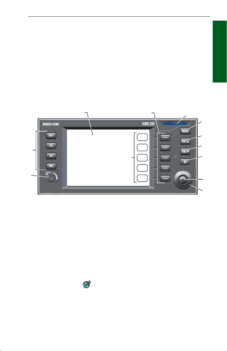
3
2
12
1
4
5
6
7
8
9
Basic Operation
Section 1
10
11
1. On/Off/Brightness Control
2. Function Select Keys
3. Display
4. Softkeys
5. Data Card
6. Menu Key
7. Range Up Key
8. Range Down Key
9. Direct-To Key
NRST (Nearest) Key
10. Joystick
11. Rotary Knob
12. Softkey Labels
Rev 4 Aug/2007 KMD 250 Pilot's Guide
1-3
Page 23

General Information
FUNCTION SELECT KEYS
These keys are used to select available data sources (as indicated on
the key) for display on the LCD. Pressing the same Function Select Key
multiple times will sequence through the available pages associated with
that function. The following diagram shows the available pages under
Section 1
each function. Note that not all pages will be available in all installations.
Basic Operation
WX TRFCFPLMAP
VFR Map
(Absolute
Terrain)
IFR Map
(No
Terrain)
Relative
Terrain Map
Active
Flightplan
Flightplan
Index
Datalink Wx
Graphical
Products
Datalink Wx
Textual
Products
Stormscope®
TAS/TCAS/TIS
MENU KEY
Displays the available Softkey options for the currently selected function.
RANGE KEYS
RNGΔ- Pressing this key will increase the range scale one level on the
displayed page. Range scales on other pages will not be affected.
RNG∇- Pressing this key will decrease the range scale one level on the
displayed page. Range scales on other pages will not be affected.
DIRECT-TO/NRST (NEAREST) KEY
The Direct-To Key (D) is found on units containing the optional
internal VFR GPS navigator. When pressed the Direct-To function is initiated. Direct-To will only function when the internal GPS is selected as
the current navigation source.
The NRST (Nearest) Key is found on units without the internal GPS
option. When pressed the Find Nearest Window will be displayed.
SOFTKEYS
When active, the description indicated in the label describes the key’s
present function related to the displayed page. Whenever a new option
is selected, a new display is shown along with its new key labels. This
Rev 4 Aug/2007
1-4
KMD 250 Pilot's Guide
Page 24

General Information
capability of displaying operations that are only applicable to a particular
screen is referred to as ‘Soft Keying’, and allows one key to perform multiple functions without the complications of multiple key presses on a
conventional keypad.
JOYSTICK
This is a pointing device which moves a mouse-like pointer around the
display. It is primarily used for pointing at items on the map for further
information and for measuring range and bearing to specific points. It is
also used to move through menu lists.
ROTARY KNOB
The Rotary Knob, located in the lower right of the unit, has various functions as indicated by a soft label when active. It is also used to move
through menu lists and change data within data fields.
STORMSCOPE®OPTION
The KMD 250 has the ability to interface and control an L-3 WX-500
Stormscope® ‘black box’ thunderstorm sensor. When the Stormscope®
interface is on and the overlay is enabled, lightning icons will also appear
on the display.
Basic Operation
Section 1
DEMO MODE
The Demo Mode can be used to practice using the KMD 250. This will
allow you to utilize it to the maximum extent.
When the KMD 250 is in the Demo Mode, it performs as if it is receiving
adequate sensor signals to use the various functions. See DEMO
MODE & SETUP later in this section.
FUNCTION STATUS ICONS
The Function Status Icons are used to show the current status of Traffic
Avoidance, Flight Information Services Weather Products and WX-500
Stormscope® functions. These icons are displayed in the lower left of
the screen. If a function is not enabled, or is not installed, that function’s
icon will not be displayed.
In general, if a Status Icon has a gray background the function is not
being displayed on the current display. This may be due to the setting
on the Map Setup Overlays Group Page. If the map display range is
beyond that set on the Map Setup Overlays Group Page, then the Status
Rev 4 Aug/2007 KMD 250 Pilot's Guide
1-5
Page 25
General Information
Icon background will be gray because that function will not be displayed
at that range setting.
If a Status Icon has a light blue (cyan) background the function is currently being displayed. This does not necessarily mean that data is visible because there may be nothing to view.
Section 1
For example, if traffic icons are set to display at 30nm on the Map Setup
Overlays Group Page and the VFR Map range is increased to beyond
Basic Operation
30nm, then traffic will no longer be overlayed on the VFR Map display
and the traffic Status Icon background will change from light blue to gray.
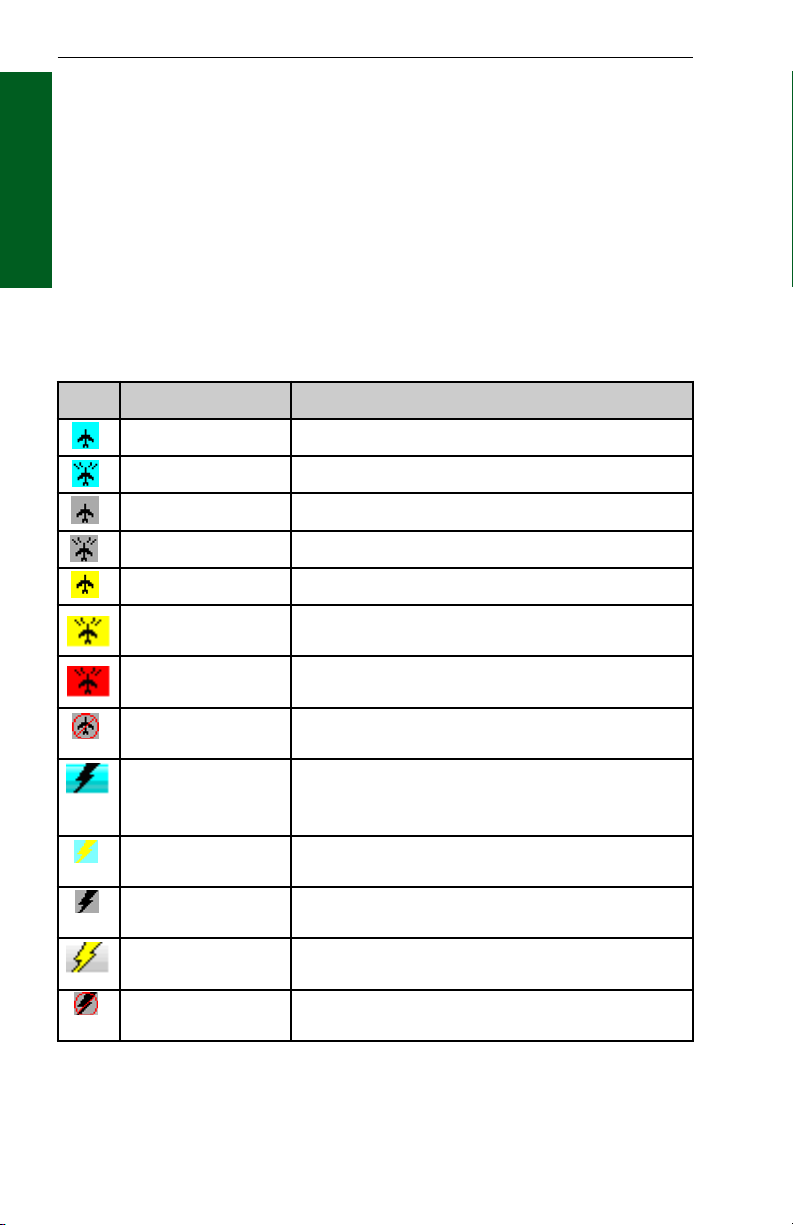
The following table illustrates the Function Status Icons and their meanings in more detail.
Icon Colors Description
Black on cyan Traffic sensor in standby mode being displayed.
Black on cyan Active traffic information being displayed.
Black on gray Traffic sensor in standby mode, not being displayed.
Black on gray Traffic sensor active, not being displayed.
Black on yellow TIS service not available.
Flashing black on
yellow
Flashing black on red A Resolution Advisory (RA) alert is active. The icon will
Black on gray with red
slash
Black on cyan
Yellow on cyan
Black on gray
Yellow on gray
Black on gray with red
slash
Rev 4 Aug/2007
A Traffic Advisory (TA) alert is active. The icon will be
flashing.
be flashing.
Traffic sensor data invalid / not being displayed.
Stormscope®information being received and displayed.<MODE> is either STRK (Strike) or CELL
depending on mode selected on Stormscope®page.
Stormscope®information being received and displayed.
Strikes have occurred within 25 nm.
Stormscope®information being received but not displayed.
Stormscope®information being received but not displayed. Strikes have occurred within 25 nm.
Stormscope®information not being received; data is
invalid.
1-6
KMD 250 Pilot's Guide
Page 26
General Information
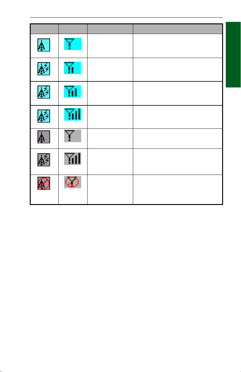
VDL Icon XM Icon Colors Description
Black on a cyan
background.
Black on a cyan
background.
Black on a cyan
background.
Black on a cyan
background.
Black on gray. Weather data not being received nor dis-
Black on gray. Weather data is currently being received
Black on gray with
red slash
No weather data is currently being
received but previously received data is
being displayed on the present page.
Weather data is currently being received
from a signal and displayed on the present page. XM signal is weak.
Weather data is currently being received
from a signal and displayed on the present page. XM signal is marginal.
Weather data is currently being received
from a signal and displayed on the present page. XM signal is good.
played on the present page.
from a signal but not displayed on the
present page.
Fault with connection or data link radio.
Basic Operation
Section 1
Rev 4 Aug/2007 KMD 250 Pilot's Guide
1-7
Page 27
General Information
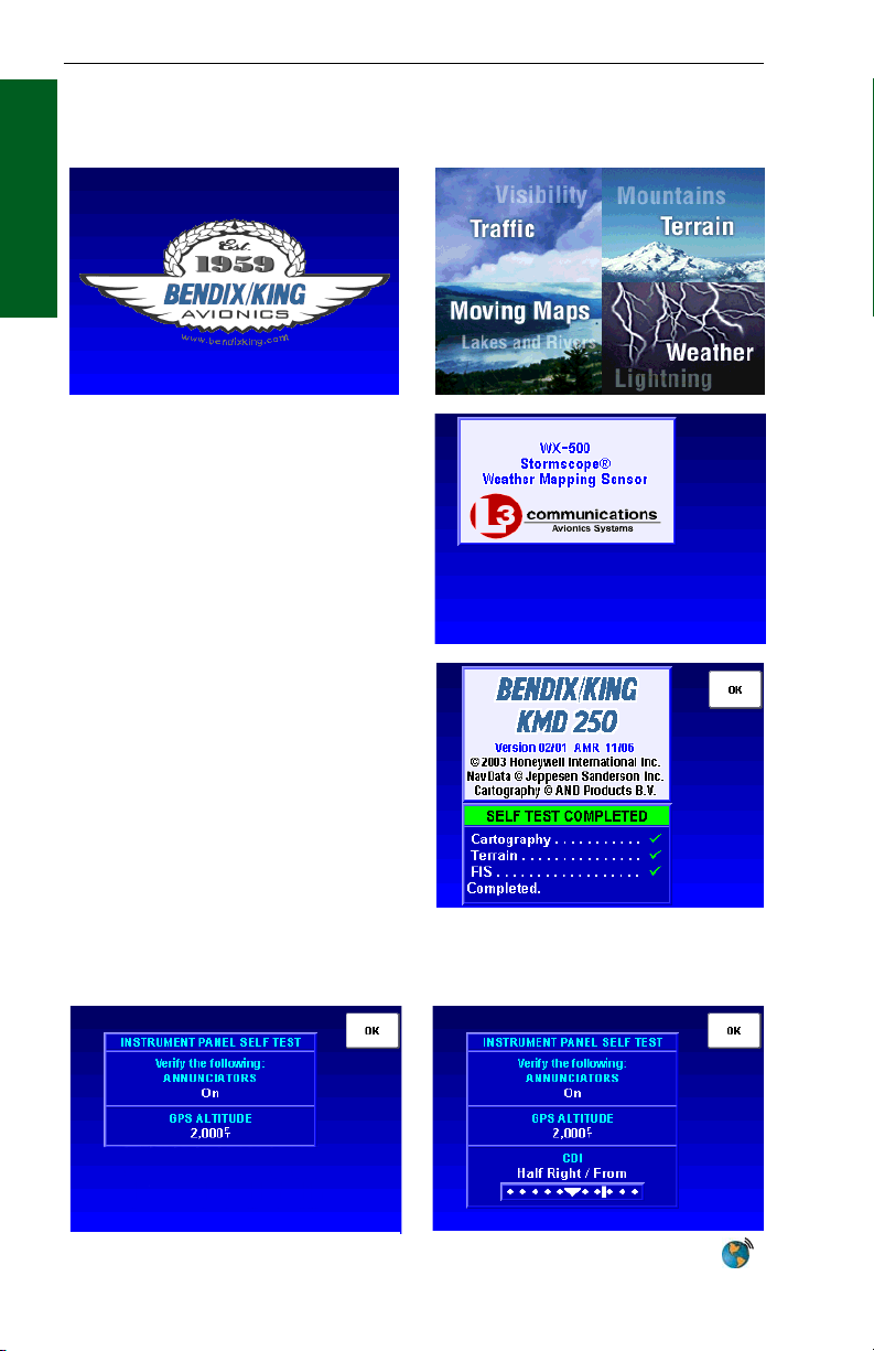
STARTUP DISPLAYS
At power-up, the startup logo displays will be seen.
Section 1
Basic Operation
If Stormscope® is installed with the
system, a display similar to the one at
the right will be seen.
After the completion of the Self Test,
press the OK Softkey.
One of the following Instrument Panel Self Test Pages will be displayed
depending on whether the unit is equipped with an internal GPS or is the
non-GPS version.
Non-GPS KMD 250
Rev 4 Aug/2007
KMD 250 with Internal GPS
1-8
KMD 250 Pilot's Guide
Page 28
General Information
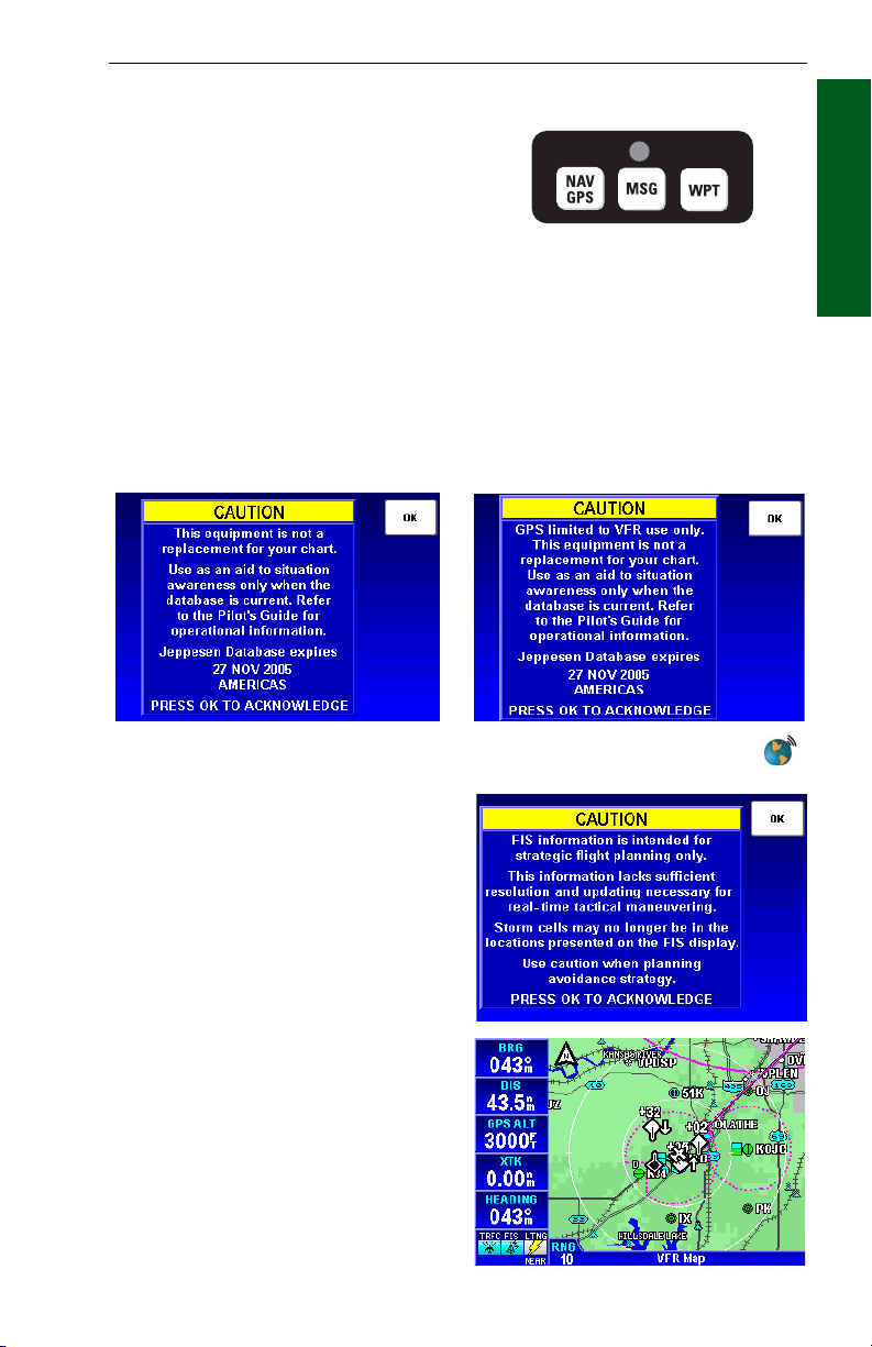
Verify that the Message and Waypoint Alert annunciator lamps are on.
These annunciators are external to the KMD 250, mounted elsewhere
on the instrument panel as shown
here represented as MSG and
WPT. However, they are optional
and may not be installed. Verify
the GPS ALTITUDE (BARO ALTI-
TUDE will be displayed if the
system is configured to use a barometric altitude source) is consistent with the altimeter. If the KMD 250 is
configured to use the optional internal GPS as “sole source” or “backup”
verify the Course Deviation Indicator (CDI) is showing half scale right
deflection with a FROM indication. If all is correct after verification, press
the OK Softkey.
One of the following caution screens will now be displayed depending on
whether the unit is the non-GPS version or the unit is equipped with the
internal GPS . Acknowledge by pressing the OK Softkey.
Typical External Annunciator Unit
Basic Operation
Section 1
Non-GPS KMD 250
Acknowledge the next caution page
by pressing the OK Softkey.
The KMD 250 is now ready for use
and will be showing the VFR Map
Display.
Rev 4 Aug/2007 KMD 250 Pilot's Guide
KMD 250 with Internal GPS
1-9
Page 29
General Information
POP-UP HELP DISPLAYS
Pop-up status displays are shown
if a Function Select Key is pressed
and held for longer than 2 seconds.
These can help provide a refer-
Section 1
ence for monitoring the status of
Basic Operation
selected functions. The first
example is a MAP Function Select
Key pop-up. Second is the pop-up
displayed when pressing and
holding the WX Function Select
Key.
Map Display Pop-Up Help
Weather Display Pop-Up Help
POWER DOWN
When power is turned off a display
similar to that shown here will be
seen. The system will shut down
in 5 seconds. This allows for inadvertently turning off the system.
Push the ON/OFF/Brightness
Control back in before the countdown is over and the system will
continue where it left off with no
loss of data.
Power Down Display
DATA FIELDS
Data Fields may be used to display various types of information in windows on the left side of the screen, as shown here. This makes it easy
to get quick access to desired information.
The Data Fields can be turned on or off and customized separately in
each of the MAP, WX or TRFC Displays. The system will remember the
last selected parameters in each function display and will maintain this
configuration until changed.
Rev 4 Aug/2007
1-10
KMD 250 Pilot's Guide
Page 30

General Information
Map Display-Data Fields OffMap Display-Data Fields On
Each field can be customized to display any of the following:
ALT Altitude
BRG Bearing to Waypoint
CDI Course Deviation Indicator
DIS Distance to Waypoint
DEP TIME Departure Time
DTK Desired Track
ESA En Route Safe Altitude
ETA WPT Estimated Time of Arrival at Waypoint
ETE WPT Estimated Time Enroute to Waypoint
FLT TIME Flight Time
GNDSPD Ground Speed
HEADING Heading
MSA Minimum Safe Altitude
NEAR POS Near Position Display
PPOS Present Position
TIME Time
TKE Track Angle Error
TRFC Traffic
TRK Actual Track
WPT Active Waypoint
XTK Cross Track Error
Basic Operation
Section 1
NOTE: Some fields may not have valid data depending on the installation.
The CDI (Course Deviation Indicator) Display has scaling of 5nm, 1nm
and .3nm depending on the setting on the Navigation Setup Page (see
Navigation Setup in this section).
Rev 4 Aug/2007 KMD 250 Pilot's Guide
1-11
Page 31

General Information
The Near Position (NEAR POS) display is intended to provide an easy
method of reporting aircraft position to Air Traffic Control. This is done
by always displaying the nearest reporting position to the aircraft’s present position in the Data Field. The position criteria can be set to display
the nearest VORs, VORs plus airports or all data (airports, VORs,
VOR/DME, VORTAC, NDB, VRP). Settings are made on the Navigation
Section 1
Setup Page discussed later in this section.
Basic Operation
To turn the Data Fields on or off,
perform the follow steps:
1. Press the MENU Key to display Figure 1-1.
2. Press the CHANGE FIELDS
Softkey to display Figure 1-2. If
the Data Fields were on to begin
with, a FIELDS OFF Softkey will
be available. If the Data Fields
were off, a FIELDS ON Softkey
will be available. Pressing this
Softkey will toggle the Data Fields
on and off.
3. When finished press the
DONE Softkey.
Figure 1-1
To change Data Fields, perform
the follow steps:
1. Perform steps 1 and 2 above.
With the Data Fields turned on,
use the Joystick to select the
desired Data Field as shown in
Figure 1-3. In this case the top
Data Field is selected and displays
BRG as indicated in the list.
2. When the desired Data Field
is selected, use the Rotary Knob to
select data from the list to be displayed in that Data Field.
These settings will be maintained
until changed by the user.
3. When finished press the DONE
Softkey.
Pressing the RESTORE DEFAULT Softkey will reset the Data Fields
back to the factory settings.
Rev 4 Aug/2007
1-12
Figure 1-2
Figure 1-3
KMD 250 Pilot's Guide
Page 32

General Information
COURSE DEVIATION INDICATOR (CDI)
A Course Deviation Indicator (CDI)
graphically displays left and right
deviation from a desired course. A
CDI can be displayed in any of the
Data Fields as shown in Figure 1-
4. The CDI’s vertical bar operates
like a navigation deviation needle
on a conventional CDI or HSI
using VOR/Localizer navigation.
An on-course indication is displayed when the vertical deviation
bar is centered on the triangle in the
middle of the CDI. In enroute use,
each dot represents one nautical
mile deviation from the desired
track (full scale deviation is ± 5
NM). Different CDI scales can be
set on the Navigation Setup Page.
A vertical deviation bar positioned
two dots to the right of the center
triangle indicates the aircraft is two
nautical miles to the left of course
as shown in Figure 1-5. The center
triangle also serves as the CDI’s
TO/FROM indicator and operates
in the same manner as a conventional CDI TO/FROM indicator; a
triangle pointing up indicates “to”
the active waypoint while a “down” triangle
(Figure 1-6) indicates “from” the active waypoint.
The word FLAG is displayed over the CDI when
the CDI is not usable for navigation as seen in
Figure 1-7.
CNU
2 NM
TUL
Basic Operation
Section 1
Figure 1-4
Figure 1-5
Figure 1-6
Figure 1-7
Rev 4 Aug/2007 KMD 250 Pilot's Guide
1-13
Page 33

General Information
GREAT CIRCLE COURSES AND MAGNETIC VARIATION
Due to “great circle” courses and magnetic variation differences between
present position and the active waypoint, the To bearing and From radial
may not be exactly 180° different from each other. This condition is
most likely to occur when long distances are involved, and/or you are
Section 1
operating in very northerly or southerly latitudes.
Basic Operation
N
N
72°
KPHX
269°
Figure 1-8
See Figure 1-8 for an example depicting a case like this. The aircraft is
somewhere over Georgia, and the active waypoint is KPHX. The bearing
to steer is 269°, and radial is 72°. Generally, bearing (not radial) will be
used when long distances are involved.
MINIMUM AND ENROUTE SAFE ALTITUDE
The Minimum Safe Altitude (MSA) displayed is the altitude defined by
Jeppesen as “Grid Minimum Off-Route Altitude (Grid MORA)”. This altitude is derived by Jeppesen for sectors which are one degree of latitude
by one degree of longitude in size. One degree of latitude is 60 nautical
miles. One degree of longitude is 60 nautical miles at the equator and
progressively less than 60 nautical miles as one travels away from the
equator. One degree of longitude is approximately 50 nautical miles at
the southern most parts of the U.S. and is approximately 40 nautical
miles at the northern most parts of the U.S. The MSA altitude information is contained in the database and is updated when the datacard is
updated.
Rev 4 Aug/2007
1-14
KMD 250 Pilot's Guide
Page 34

General Information
The MSA provides “reference point” clearance within these one degree
latitude by one degree longitude sectors. Jeppesen defines a reference
point as “a natural (Peak, Knoll, Hill, etc.) or man-made (Tower, Stack,
Tank, Building, etc.) object”. Jeppesen states the following about the
Grid Minimum Off-Route altitude: “Grid MORA values clear all reference
points by 1000 feet in areas where the highest reference points are 5000
feet MSL or lower. MORA values clear all reference points by 2000 feet
in areas where the highest reference points are 5001 feet MSL or
higher”. The KMD 250 displays dashes for areas outside the database
coverage area or for areas where the Grid MORA is not defined.
The Enroute Safe Altitude (ESA) is the highest MSA sector altitude from
the present position to the active waypoint, then to the destination waypoint along the active flight plan. See Figure 1-9. When the KMD 250 is
in the OBS Course Mode, the minimum en route safe altitude is the
highest MSA sector altitude from the present position to the active waypoint.
ESA (MSL)
MSA (MSL)
1°
LAT.
Basic Operation
Section 1
1° LONG.
Figure 1-9
CAUTION
The MSA and ESA altitudes displayed are advisory only. They
should not be relied upon as the sole source of obstacle and terrain avoidance information. Refer to current aeronautical charts for
appropriate minimum clearance altitudes.
Rev 4 Aug/2007 KMD 250 Pilot's Guide
1-15
Page 35

General Information
INTERNAL GPS STATUS
For an overview on how the
Global Positioning System works,
refer to Appendix C, GPS Primer.
Section 1
Such parameters as present posi-
Basic Operation
tion, altitude, date, time, satellite
state, DOP, satellites tracked,
signal strength and elevation for
the internal GPS can be monitored
on the Internal GPS Status Page.
To access this page perform the
following:
1. Press the MENU Key to display Figure 1-10.
2. Press the AUX MENU Softkey
to display Figure 1-11.
3. Using the Rotary Knob or the
Joystick to select Internal GPS
Status as shown in Figure 1-11.
Figure 1-10
4. Press the SELECT Softkey to
display Figure 1-12.
5. Press the RCVR INFO
Softkey to view information such
as the GPS receiver software part
number, software version, software revision and serial number
as shown in Figure 1-13.
QUICKTUNE™
The KMD 250 is capable of tuning
the KX 155A/165A Nav/Comm.
The KMD 250 is capable of tuning
up to four Nav/Comm systems,
depending on the installation. Use
of this feature will be discussed
later in Map Operation and Flight
Planning.
Rev 4 Aug/2007
1-16
Figure 1-11
Figure 1-12
Figure 1-13
KMD 250 Pilot's Guide
Page 36

Map Operation
MAP OPERATION
The following illustration describes the data that appears on the Map
Display.
3
4
5
6
7
2
8
9
1
11
10
Basic Operation
Section 1
1 Function Status Icons - Displays icons representing data available and
displayed as well as sensor status.
2 Data Fields - These can be turned on or off. Each of the 5 windows can
be set to display one of the following; ALT, BRG, CDI, DIS, DEP TIME, DTK,
ESA, ETA WPT, ETE WPT, FLT TIME, GNDSPD, HEADING, MSA, NEAR
POS, PPOS, TIME, TKE, TRFC, TRK, WPT, XTK.
3 North Pointer
4 Aircraft Symbol - Indicates present position. Stylized airplane when heading
or track input is present, a plus symbol with no heading or track.
5 Range Rings - Outer ring radius is selected range, inner ring radius is one
half the selected range.
6 RESET STICK Soft Label
7 Traffic Symbol Overlay - Displayed when traffic avoidance system is installed.
8 Graphical METAR Icon Overlay - Displayed when FIS is installed and
subscription is valid.
9 LEGEND Soft Label
10 Current MAP Selection - VFR MAP (absolute altitude terrain shading), IFR
MAP (no terrain shading) or Relative Terrain Map (relative altitude terrain
shading).
11 Display Range - RNG:####.
Rev 2 Apr/2004
1-17
KMD 250 Pilot's Guide
Page 37

Map Operation
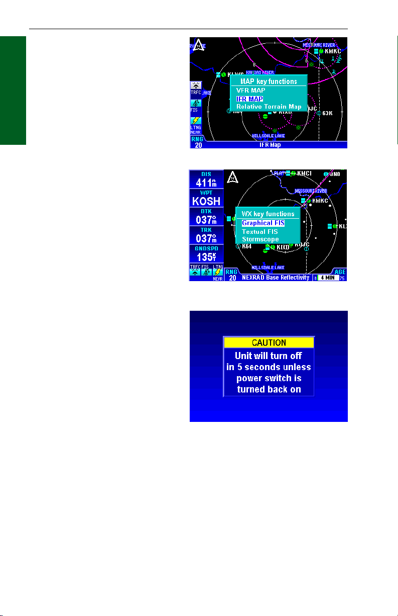
SELECTING A MAP DISPLAY
Press the MAP Function Select Key to sequence through the VFR Map,
IFR Map and Relative Terrain Map Display. With the IFR Map displayed,
no topographic data is displayed. With the Relative Terrain Map displayed, topographic data is displayed as colors corresponding to eleva-
Section 1
tion relative to the aircraft’s present altitude. See Tables 1-1 and 1-2 on
Basic Operation
Absolute and Relative Altitudes.
VFR Map
☞
IFR Map
Relative Terrain
Map
VFR MAP
With the VFR Map displayed,
topographic data is displayed
as colors corresponding to the
absolute altitude stored in the
database (see Figure 1-14).
The VFR Map displays terrain
similar to a VFR sectional
chart. Table 1-1 shows the
levels and terrain shading used
on the VFR Map.
A color key can be displayed
by moving the Joystick Pointer
pressing the LEGEND Softkey
as shown in Figure 1-15. To
exit, press the CLEAR Softkey
then press the RESET STICK
Softkey.
Rev 2 Apr/2004
Figure 1-14 - VFR Map
Figure 1-15
Absolute Terrain Color Key
1-18
KMD 250 Pilot's Guide
Page 38

Map Operation
Absolute Terrain Altitude (feet) Color
13000+ Dark Brown
11500-12999
10000-11499
9000-9999
8000-8999
7000-7999 Light Brown
6000-6999 Dark Tan
5000-5999
4000-4999
3000-3999
2500-2999
2000-2499 Light Tan
1500-1999 Dark Green
1000-1499
500-999
<499 Light Green
Water Blue
Table 1-1 Absolute Terrain (VFR Map)
IFR MAP
Terrain is not displayed on the
IFR Map display as shown in
Figure 1-16. In addition, all
built up or urban areas are
shaded light gray. Oceans,
rivers and lakes are blue.
Basic Operation
⇓
⇓
⇓
⇓
⇓
⇓
⇓
⇓
⇓
⇓
Section 1
RELATIVE TERRAIN MAP
With Relative Terrain Map displayed, topographic data and
obstructions are displayed as
colors corresponding to elevation relative to the aircraft’s
present altitude as shown in
Figure 1-17. This feature is
useful in providing awareness
to possible terrain hazards at
the present aircraft altitude.
Table 1-2 shows the levels and
terrain shading used on the
Relative Terrain Map.
Rev 2 Apr/2004
Figure 1-16 - IFR Map
Figure 1-17 - Relative Terrain Map
1-19
KMD 250 Pilot's Guide
Page 39

Map Operation
Aircraft Altitude Relative to
Terrain (feet)
250 ft. or more below sur-
rounding terrain
Between 249 ft. below & 250
ft. above surrounding terrain
Section 1
Between 251 ft. & 750 ft.
Basic Operation
above surrounding terrain
Between 751 ft. & 1250 ft.
above surrounding terrain
Between 1251 ft. & 2000 ft.
above surrounding terrain
2001 ft. or more above sur-
rounding terrain
Aircraft Altitude Relative to
Obstacle (feet)
250 ft. or less above obstacle
Between 251 ft. & 750 ft.
above obstacle
Between 751 ft. & 1250 ft.
above obstacle
Between 1251 ft. & 1750 ft.
above obstacle
Between 1751 ft. & 2000 ft.
above obstacle
2001 ft. or more above
obstacle
Table 1-2 Relative Terrain and Obstacles (Relative Terrain Map)
Color
100% Black
Figure 1-18
Relative Terrain Color Key
Relative Obstacle Color Key
Figure 1-19
A color key can be displayed by
moving the Joystick Pointer and
pressing the LEGEND Softkey.
Notice there are two legends when
viewing the Relative Terrain Map
Display. The first page shows the
color key for terrain (Figure 1-18)
and the second (Figure 1-19)
shows the color key for obstacles.
The airplane icon conveys what
colors would be below current aircraft altitude and what would be
above. The airplane icon itself,
Figure 1-20
however, does not represent current aircraft altitude. Press the NEXT
and PREV Softkeys to toggle between the two displays. To exit, press
the CLEAR Softkey then press the RESET STICK Softkey.
Figure 1-20 depicts obstacles displayed on the Relative Terrain Map.
Note the differences in color between terrain and obstacles based on an
aircraft altitude of 2,000 ft MSL. Obstacles are enhanced on the Relative
Rev 2 Apr/2004
1-20
KMD 250 Pilot's Guide
Page 40

Map Operation
Terrain display to provide situational awareness by displaying a 1/2 nm
ring around the obstacle. For example, the obstacles displayed with a
red ring, as shown in Figure 1-20, are easily identifiable and are within
250 ft. of the present aircraft altitude.
NOTE: The color scale for obstacles is more severe than terrain so that
they stand out on the map.
CAUTION
NEVER USE THE TOPOGRAPHIC ELEVATION DISPLAYED ON
THIS EQUIPMENT AS YOUR SOLE REFERENCE FOR TERRAIN
AVOIDANCE.
The KMD 250 must be receiving altitude information from an altitude
source for the Relative Terrain Map to function. Altitude sources may be
GPS altitude, pressure altitude (ARINC 429 or Gillham) or baro-corrected altitude. The altitude
source options are determined
at installation. If no altitude
information is received a caution will be displayed as in
Figure 1-21.
NOTE: If a baro-corrected or
pressure altitude source is
used, the Relative Terrain Map
may not display colors accurately in operations above
18,000 feet when the altimeter
setting is 29.92 in. Hg.
Figure 1-21
Basic Operation
Section 1
Baro Correction
If the altitude information
source is Gillham pressure altitude, then a baro correction
must be entered manually. If
the baro correction is not kept
current the Relative Terrain
Map will not display the proper
color coding for the aircraft’s
actual altitude.
When on the Relative Terrain
Map the KMD 250 will prompt for an entry every 30 minutes as shown in
Figure 1-22. Turn the Rotary Knob to enter the desired barometric setting. After the desired setting is entered, press the OK Softkey.
Figure 1-22
NOTE: The manual baro correction entry must be kept current on both
the KMD 250 and the altimeter for the Relative Terrain Map to function
properly.
Rev 2 Apr/2004
1-21
KMD 250 Pilot's Guide
Page 41

Map Operation
The baro correction may also
be entered through the AUX
MENU as follows:
1. Press the MENU Key to
display the Menu Softkeys as
in Figure 1-23.
Section 1
Basic Operation
2. Press the AUX MENU
Softkey to display Figure 1-24.
Use the Joystick to select Baro
Entry as shown.
3. Press the SELECT
Softkey and Figure 1-25 will be
displayed.
4. Turn the Rotary Knob to
select the desired entry.
5. Press the OK Softkey.
OBSTACLE LABELS
Figure 1-23
Obstacles are labeled with two
numbers. The first number is
the height of the obstacle in
FEET ABOVE MSL. The
second number (in brackets) is
the height of the obstacle in
FEET AGL.
Rev 2 Apr/2004
1-22
Figure 1-24
Figure 1-25
KMD 250 Pilot's Guide
Page 42

Map Operation
USING THE MAP
After power-up, the map
will initially be displayed at
a range setting of 20nm.
If there is no valid GPS or
FMS position fix data
available, the words
CAUTION, No position
data will be shown across
the center of the display in
a box as seen in Figure 1-
26. If the fix is lost at any time during normal operation of the unit, the
same CAUTION, No position data box will be overlayed on the map.
CAUTION: Do not use the map for navigation while this notification
is displayed.
The map will be shown in either North Up, Track Up or Heading Up
orientation depending upon the setting selected in the Map Setup and is
reflected by the North Pointer in the upper left of the display.
The displayed data is updated every second. Press the
RNGΔΔ(range up) or RNG∇∇(range down) key at any time
to zoom the map in and out to whichever one of the twelve
pre-set scales desired. The available range settings are 1,
2.5, 5, 10, 15, 20, 30, 50, 100, 150, 200, 300, 500 and
1000 nm. The levels of detail appearing at each zoom
level can be changed in the Map Setup menu. See Map
Setup.
Figure 1-26
Basic Operation
Section 1
When active, Auto Zoom automatically adjusts the range setting up or
down as needed to keep the flight plan active waypoint within the viewable area of the Map display.
Auto Zoom is enabled in either of the following ways:
1. Pressing RNG
minimum setting of 1 nm.
2. Pressing and holding
either RNG Key for 2 seconds
or more. While Auto Zoom is
enabled, AUTO is displayed in
light blue text above the current
range setting (see Figure 1-
27).
Auto Zoom will be canceled if
the flight plan becomes invalid
or either RNG Key is pressed.
Rev 2 Apr/2004
∇∇
past the
1-23
Figure 1-27
KMD 250 Pilot's Guide
Page 43

Map Operation
MAP DATA
INTERROGATION
As soon as the joystick is
moved, a display similar to
Figure 1-28 will be displayed.
Section 1
The map freezes in its present
Basic Operation
position with respect to the
joystick pointer (inset). The
reason the map is made to
stop moving is that this makes
accurate positioning of the joystick pointer much easier.
The aircraft icon will still be
displayed in the proper location and will move in relation
to the stationary map.
The latitude and longitude of
the pointer position is displayed at the bottom of the
display. The bearing (PBRG)
and distance (PDIS) are also
displayed. These show the
distance and bearing from the
aircraft present position to the
joystick pointer. This function
can be used to measure distance and bearing to any point
on the map. The window
formed by the extremities of
the display can be moved
(panned) around the map by
"bumping" the display borders
left, right, up or down with the
pointer. The RNGΔΔand RNG
∇∇
keys can still be used to
zoom the map in and out.
Press RESET STICK and the
joystick pointer will vanish, the display will return to the moving map,
and the map will be placed back in its present position at the zoom
level that was selected prior to activating the joystick. If the joystick is
not moved for 30 seconds, the display will time-out back to the moving
map.
Figure 1-28
Figure 1-29
Figure 1-30
In addition to finding it useful for measuring distances and bearings,
the joystick can be used for other tasks. By placing the pointer over
any data icon a window will pop up similar to that shown in Figure 1-
29. Pressing the MORE INFO Softkey, a display similar to Figure 1-30
will appear.
Rev 2 Apr/2004
1-24
KMD 250 Pilot's Guide
Page 44

Map Operation
Press the CLEAR Softkey to return to the map display.
If the FIS INFO Softkey is pressed, the textual METAR page will be
displayed for the closest reporting station to the current selection.
AIRPORT INFORMATION
As shown in Figure 1-31, you
can display airport information
by placing the joystick pointer
over an airport icon. Pressing
the MORE INFO Softkey will
display more detailed runway
information as shown in
Figure 1-32. The RNG Keys
can be used to zoom in or out
on the airport diagram. The
information given here is
derived from the database.
The airport type is shown to
the right of the airport identifier
(KOSH). The airport type is
either MILITARY, PRIVATE
or blank for others (public).
The airport elevation (808ft) is
shown to the right of the airport type. Runway orientation
and lengths are displayed to
the right of the airport diagram. Runway surfaces are
shown as an H for hard and
an S for soft. Lighting is
shown as an L for lit and a U
for unlit.
Figure 1-31
Figure 1-32
Basic Operation
Section 1
Pressing the NEXT Softkey
will display more details like
radio frequencies and services, similar to Figure 1-33.
In the window with the airport
identifier, airport airspace
information and approach
types will be shown. The next
window to the right shows the
difference between UTC and
local standard and daylight
times. The next window will display the available fuel types at this airport. See Figure 1-35 for details regarding these fields.
Rev 2 Apr/2004
1-25
Figure 1-33
KMD 250 Pilot's Guide
Page 45

Map Operation
If the FIS INFO Softkey is pressed, the textual METAR page will be displayed with the current METAR report (if available) for this airport or
the nearest report to the airport.
Pressing the QUICK TUNE
Softkey will tune the appropriate KX 155A/165A
Section 1
Nav/Comm to the selected
Basic Operation
frequency. Use the Joystick
or Rotary Knob to place the
cursor over the desired frequency in the list. If the
system contains only one KX
155A/165A, simply pressing
the QUICK TUNE Softkey will
tune the Nav/Comm to the
selected frequency. If multiple
KX 155A/165A systems are contained in the installation, pressing the
QUICK TUNE Softkey will display the Nav or Comm selection display
as shown in Figure 1-34. Use the Joystick or Rotary Knob to select the
desired Nav or Comm for tuning. Press the OK Softkey to tune the
radio.
Figure 1-34
Rev 2 Apr/2004
1-26
KMD 250 Pilot's Guide
Page 46

Map Operation
2
1
3
4
5
1 Airport ICAO Identifier
2 Airspace Enviroment - The following may be displayed in this field:
CL B Class B airspace
CL C Class C airspace
CTA Control Area
TMA Terminal Area
TRSA Terminal Radar Service Area
3 Non GPS Approach Availability - The following may be displayed in this
field:
NO APR No approaches are available
NP APR Non-precision approach available
MLS MLS approach available
ILS ILS approach available
ILS/MLS ILS and MLS approaches available
4 GPS Approach Availability - If an approved non-precision GPS approach
is available GPS will be displayed.
5 Comm Frequency List - Lists the available communications frequencies for
the airport being displayed. See Appendix A for abbreviations.
6 Fuel Availability - The following fuel types may be displayed:
80 80 to 87 octane
100 100 to 130 octane
100LL 100 octane, low lead
JET Jet fuel, any type
AUTO Automotive fuel (also known as MOGAS)
7 Time Zone - Displays the difference between local standard time and UTC
for the selected airport. The difference in local daylight time and UTC is in
parenthesis.
8 Radar Indicator - If (R) is displayed, this indicates an approach/departure
radar environment.
Figure 1-35 Airport Info Field Definitions
NAVAID INFORMATION
Basic Operation
6
Section 1
7
8
As explained previously, you
can access additional Navaid
information by placing the joystick pointer over a VOR or
NDB icon to display information similar to Figure 1-35.
Pressing the MORE INFO
Softkey will display more information as in Figure 1-36. Full
details of the Navaid are listed,
Rev 2 Apr/2004
1-27
Figure 1-36
KMD 250 Pilot's Guide
Page 47

Map Operation
type, frequency and ident as
shown in Figure 1-37.
As discussed previously in
Airport Information, pressing
the QUICK TUNE Softkey will
tune the appropriate KX
Section 1
155A/165A Nav/Comm to the
Basic Operation
navaid frequency. If the
system contains only one KX
155A/165A, simply pressing
the QUICK TUNE Softkey will
tune the Nav radio. If multiple
KX 155A/165A systems are
contained in the installation,
pressing the QUICK TUNE
Softkey will display the Nav
selection display as shown in
Figure 1-38. Use the Joystick
or Rotary Knob to select the
desired Nav or Comm for
tuning. Press the OK Softkey
to tune the radio.
Figure 1-37
AIRSPACE
INTERROGATION
In order to interrogate a piece
of airspace on the Map display,
move the joystick pointer to
one of the airspace boundaries
to display an information
window as shown in Figure 1-
39.
IMPORTANT:
When a single airspace
boundary line is shared by
two different pieces of airspace (which is very common), the airspace with the lower vertical
limit will always be highlighted.
Once it is determined the piece of airspace highlighted is the piece for
which information is wanted (you may have to zoom out to verify this, but
beware, some airspace switches off as you zoom out dependent on the
settings made in Map Setup), press the MORE INFO Softkey and additional information will be displayed as in Figure 1-40.
Rev 2 Apr2004
1-28
Figure 1-38
Figure 1-39
KMD 250 Pilot's Guide
Page 48

Map Operation
The information shown on this
display is all the information
from the internal database that
is relevant to the airspace
selected. If some of the fields
are blank or say SEE CHART,
this means that Jeppesen data
is not available for that particular item.
As discussed previously,
pressing the QUICK TUNE
Softkey will tune the appropriate KX 155A/165A
Nav/Comm to the selected frequency. Use the Joystick or
Rotary Knob to place the
cursor over the desired frequency in the list. If the
system contains only one KX
155A/165A, simply pressing
the QUICK TUNE Softkey will
tune the Comm to the
selected frequency. If multiple
KX 155A/165A systems are
contained in the installation,
pressing the QUICK TUNE
Softkey will display the Comm selection display as shown in Figure 1-
35. Use the Joystick or Rotary Knob to select the desired Comm for
tuning. Press the OK Softkey to tune the radio.
Figure 1-40
Figure 1-41
Basic Operation
Section 1
AIRSPACE ALERTING
The Special Use Airspace (SUA) alert feature is three dimensional. The
SUA areas are stored in the KMD 250 database with regard to altitude
when the actual SUA altitude limitations are charted in terms of mean
sea level (MSL). However, if the actual lower limit of an SUA is charted
in terms of an altitude above ground level (AGL), then it is stored in the
database as all altitude below the upper limit of the SUA. If the actual
upper limit of an SUA is charted in terms of AGL, it is stored in the database as “unlimited”.
If the altitude input to the KMD 250 is pressure altitude from an altitude
encoder or air data computer, then you must manually update the KMD
250 with an altimeter setting (Baro Correction) in order to receive accurate SUA alerting. See the discussion on Baro Correction earlier in this
section. It is a good idea to update the Baro Correction each time you
make a change to the aircraft’s altimeter setting.
Rev 2 Apr/2004
1-29
KMD 250 Pilot's Guide
Page 49

Map Operation
NOTE: If there is no altitude input to the KMD 250, all altitudes will be
regarded as being within the boundary of the SUA area.
The message prompt for a special use airspace alert will occur when the
aircraft’s position is at a point such that a projection of the aircraft’s
existing track over the ground is approximately 10 minutes from pene-
Section 1
trating the outer boundary of one of these areas. It will also occur if the
Basic Operation
aircraft is within approximately two nautical miles of
one of these areas even if
the aircraft’s projected track
over the ground won’t actually penetrate the SUA area
(see Figure 1-42). If one of
2 MILES
the SUA areas is penetrated,
another message will state:
Inside SUA.
The SUA alert feature may
be disabled (or enabled) on
the Navigation Setup Page.
See Navigation Setup later
in this section.
Figure 1-42
If the SUA alert feature has been enabled, the KMD 250 allows selection
of a vertical buffer on the in order to provide an additional layer of protection from inadvertently entering an SUA. The vertical buffer serves to
“stretch” the SUA area in both directions (up and down) by the selected
buffer altitude. For example, a buffer of 1,000 feet is selected and the
actual SUA area exists from 5,000 feet MSL to 12,000 feet MSL. In this
case SUA alert messages are displayed if the aircraft enters the lateral
boundary at any altitude between 4,000 and 13,000 feet MSL.
10 MIN
CAUTION
It is the pilot’s responsibility to avoid special use airspace where
ATC clearance to penetrate is required but has not been obtained.
The airspace alert is only a tool to assist the pilot and should never
be relied upon as the sole means of avoiding these areas.
Rev 2 Apr/2004
1-30
KMD 250 Pilot's Guide
Page 50

When SUA Alerting is enabled,
an Airspace Alert message will
be provided when the aircraft is
approximately 10 minutes or 2
miles (depending on ground
speed) from entering the airspace boundary. When an
Airspace Alert message is
given, MESSAGE PRESS
MENU will flash at the bottom
of the display as shown in
Figure 1-43.
Pressing the MENU Key will
display the message as shown
in Figure 1-44. Press the OK
Softkey to exit the message.
To enable or disable SUA
Alerting perform the following:
1. Press the MENU Key.
Press the AUX MENU Softkey
to display Figure 1-45.
2. Use the Rotary Knob or
the Joystick to place the cursor
over Navigation Setup as
shown in Figure 1-45.
Map Operation
Basic Operation
Section 1
Figure 1-43
Figure 1-44
Rev 2 Apr/2004
1-31
Figure 1-45
KMD 250 Pilot's Guide
Page 51

Map Operation
3. Press the SELECT Softkey
to display Figure 1-46.
4. Press the NEXT Softkey to
display Figure 1-47.
5. Use the Joystick to place
Section 1
the cursor in the selection field
Basic Operation
for SUA Alerting.
6. Use the Rotary Knob to
select On or Off.
7. When On is selected the
SUA Alerting Buffer will be
editable. Use the Joystick to
place the cursor over this field
(see Figure 1-48) and use the
Rotary Knob to select the
desired altitude. An Airspace
Alert message will be given
when the aircraft enters within
this selected buffer altitude
from the published SUA altitude boundary. For example: if
the published upper SUA
boundary is 3,000 feet and a
buffer altitude of 1,000 feet is
selected, the Airspace Alert will
be issued when the aircraft
descends to 4,000 feet and is
within the lateral SUA boundaries.
Figure 1-46
Figure 1-47
Rev 2 Apr/2004
1-32
Figure 1-48
KMD 250 Pilot's Guide
Page 52

Map Operation
DISPLAY FLIGHT PLAN
DATA ON MAP
If a host GPS is outputting data
in the Bendix/King equivalent
ARNAV R-30 (RS232) data
sentence format, in LEG mode,
the active flight plan will be
sent to the KMD 250 and is displayed as an overlay on the
map as shown in Figure 1-49.
If a KLN 94 is supplying the
GPS data, and the KLN 94 is
configured to produce the
“Enhanced RS-232 GPS bus”,
the KMD 250 will display the
curved paths including DME
arcs, Procedure Turns and
Holding Patterns. Figure 1-50
shows an example.
If another type of GPS is used,
then during the curved flight
segments of approaches (i.e.
DME arcs, procedural turns
and holds) most GPS units
stop outputting flight plan data but continue to output positional data.
During a DME arc or procedural turn, the KMD 250 will continue to show
position, track and ground speed but the curved line depicting the arc or
turn will not be displayed. In OBS mode, some GPS units will not be
able to provide flight plan data. Present position is still provided and
flight plans will be displayed as soon as the mode is returned to LEG.
Figure 1-49
Figure 1-50
Basic Operation
Section 1
CAUTION
In the case of DME arcs, turns and holds, some GPS units send the
flight plan information as if there was no arc or curved flight path.
Therefore the KMD 250 has no option but to connect the beginning
and end waypoints of the arc or curve with a straight line. Under
these circumstances the line on the KMD 250 MUST BE IGNORED.
Rev 2 Apr/2004
1-33
KMD 250 Pilot's Guide
Page 53

Map Operation
TEMPORARILY DECLUTTERING THE MAP
Sometimes it is necessary to
temporarily reduce the amount
of data displayed on the map in
Section 1
order to make it more readable.
Basic Operation
This is known as decluttering.
Perform the following steps
until the desired level decluttering is achieved.
1. Press the MENU Key to
display the DECLUTTER
Softkey as shown in Figure 1-
51.
2. Press the DECLUTTER
Softkey. On the first press the
land data will be removed from
the display as seen in Figure 1-
52. Notice roads, railways, city
icons, etc. are no longer displayed. Note also that a -L is
now shown in the bottom left of
the screen indicating the display is minus land data.
Figure 1-51
Figure 1-52
3. Press the DECLUTTER
Softkey again. On the second
press the aeronautical data will
be removed from the display
as seen in Figure 1-53. Notice
airports, airspace boundaries,
etc. are no longer displayed.
Note also that a -A is now
added in the bottom left of the
screen indicating the display is
also minus aeronautical data in
addition to land data.
Rev 2 Apr/2004
1-34
Figure 1-53
KMD 250 Pilot's Guide
Page 54

Map Operation
4. Press the DECLUTTER
Softkey again. The third press
will now restore the land data
as seen in Figure 1-54. Note
that the -L is no longer shown
in the bottom left of the screen
indicating land data is now
being displayed.
5. Press the DECLUTTER
Softkey again. The fourth
press will now restore the
aeronautical data.
When leaving the Map display to view another function, all data will be
restored.
FIND NEAREST (UNITS WITHOUT INTERNAL GPS)
Find Nearest allows the user to find the airport, VOR, NDB, intersection
or user entered waypoint closest to the aircraft’s present position. Up to
20 of the find criteria may be listed and must be within 200nm of the aircraft’s position. The closest will be listed first, the furthest listed last.
1. Press the NRST Key to
display the FIND NEAREST
display as shown in Figure 1-
55. In this case a list of airports is displayed.
Figure 1-54
Basic Operation
Section 1
2. If more information on a
particular airport is desired, use
the Joystick or Rotary Knob to
place the cursor over the
desired airport identifier and
press the MORE INFO Softkey.
Information on the selected airport will be displayed as in
Figure 1-56. Press the NEXT
Softkey to display more information. Press the CLEAR
Softkey to return to the FIND
NEAREST display.
Rev 2 Apr/2004
1-35
Figure 1-55
Figure 1-56
KMD 250 Pilot's Guide
Page 55

Map Operation
3. To change to one of the
other Find parameters, press
the NEAREST TYPE Softkey
to display the SELECT
NEAREST TYPE window as
shown in Figure 1-57.
Section 1
4. Use the Joystick or Rotary
Basic Operation
Knob to place the cursor over
the desired Find type.
5. Press the OK Softkey.
6. If Airports is selected as
the type (as in Figure 1-57),
pressing the AIRPORT
FILTER Softkey (Figure 1-58)
will display the AIRPORT
FILTER CRITERIA Window
as shown in Figure 1-59.
7. The listed airports can be
filtered by runway length and
runway type. Use the Joystick
to place the cursor over the
desired field and use the
Rotary Knob select the the
desired value. When finished
press the OK Softkey.
Figure 1-57
Figure 1-58
Rev 2 Apr/2004
1-36
Figure 1-59
KMD 250 Pilot's Guide
Page 56

FIND NEAREST (UNITS
WITH INTERNAL GPS)
As discussed previously, Find
Nearest allows the user to find
the airport, VOR, NDB, intersection or user entered waypoint closest to the aircraft’s
present position. Up to 20 of
the find criteria may be listed
and must be within 200nm of
the aircraft’s position. The
closest will be listed first, the
furthest listed last.
1. Press the Direct-To (D)
Key to display the DIRECT TO
window. If the KMD 250 is not
presently navigating using the
internal GPS, but is displaying
information coming from an
external GPS source, Figure 160 will be displayed. This is a
prompt to indicate the Direct-To
function is not available when
using an external GPS source.
However, this will not
affect the Find Nearest
feature. Press the OK
Softkey to display the
FIND NEAREST display.
The Find Nearest feature
is now used as discussed
previously.
Map Operation
Basic Operation
Section 1
Figure 1-60
Figure 1-61
If the KMD 250 is
presently navigating using
the internal GPS, Figure 160 will not be displayed and
Figure 1-61 will be shown
immediately upon pressing the Direct-To Key.
2. Press the NEAREST Softkey to go to the FIND NEAREST display
as shown in Figure 1-62. The balance of the Find Nearest feature functions as discussed previously.
Rev 2 Apr/2004
1-37
Figure 1-62
KMD 250 Pilot's Guide
Page 57

Map Operation
WAYPOINT ALERT
The Waypoint Alert will flash
the next desired track (NEXT
DTK) when the estimated time
to the next waypoint is about
Section 1
15 seconds as shown in Figure
Basic Operation
1-63. Turning to establish the
NEXT DTK will aid in intercepting the next leg of the flight
plan.
If the waypoint is being displayed in a Data Field the WPT field will flash annunciating the Waypoint
Alert.
When viewing the Flight Plan Page the arrow indicating the current leg
will flash to annunciate the Waypoint Alert.
If an external Waypoint Alert annunciator is installed in the aircraft, it will
also flash.
TURN ANTICIPATION
Figure 1-63
When Turn Anticipation is
enabled in Navigation Setup, it
will provide turn guidance to a
new course for intercepting the
next leg of the flight plan.
Waypoint Alerting will begin
when the estimated time to the
start of the turn is about 20
seconds. As previously discussed, the Waypoint Alert will
be annunciated by flashing the
next desired track (NEXT
DTK) window as in Figure 1-
64. When the computed turn
point is reached TURN TO will
displayed as shown in Figure
1-65. The required bank angle
to follow the arc will normally
be between 3° and 25°
depending on aircraft speed
and the amount of course
change.
Rev 2 Apr/2004
1-38
Figure 1-64
Figure 1-65
KMD 250 Pilot's Guide
Page 58

Map Operations
Turn Anticipation will be inhibited if the angle between the legs is less
than 5° or greater than 175° or the Crosstrack Error (XTK) is greater than
4 nm.
To utilize the Turn Anticipation feature, start the turn transition to the next
leg in the flight plan at the very beginning of the computed turn point.
Upon reaching this computed turn point the Waypoint Alert annunciator
will stop flashing and remain on steadily while the text “TURN TO” is displayed as shown in Figure 1-65.
If an autopilot is engaged, this is the time to change the selected course
on the CDI or HSI to that indicated next to TURN TO. In the case of
Figure 1-65 that would be 288° magnetic.
Basic Operation
Section 1
Rev 2 Apr/2004
1-39
KMD 250 Pilot's Guide
Page 59

Map Operation
Section 1
Basic Operation
Intentionally left blank
Rev 2 Apr/2004
1-40
KMD 250 Pilot's Guide
Page 60

User Waypoints
USER WAYPOINTS
User waypoints can be entered as either user defined waypoints or as
airports. The KMD 250 allows for the programming of up to 1,000 user
waypoints. User waypoints are stored on the KMD 250 data card and
can be transferred to a new data card when installed.
These waypoints can be used for flight plans if the KMD 250 contains the
optional internal GPS, but only if the internal GPS is currently being used
for navigation. Flight plans running on an external GPS cannot utilize
waypoints stored in the KMD 250.
KMD 250 systems that do not have the internal GPS also allow user
waypoints to entered, but can only be used for marking points on the
map for such things as points of interest, landing locations not contained
in the database, etc.
ENTERING A USER WAYPOINT
The following illustration describes the User Waypoint Edit display.
9
1
8
2
Basic Operation
Section 1
3
4
5
1 Waypoint Identifier - The system default will initially be USR000 and will increment with
each entered waypoint up to USR999. Any combination of alphanumeric characters
(up to six places) may be entered in place of the default.
2 1st Remarks Field - The default entry is current date. This field may be cleared and any
combination of up to 24 alphanumeric and punctuation characters may entered.
3 2nd Remarks Field - The default entry is current time. This field may be cleared and any
combination of up to 24 alphanumeric and punctuation characters may entered.
4 Waypoint Latitude/Longitude - Initially, the aircraft position at the time this display was
selected is entered here. This field may be changed to place the waypoint at different
location.
5 Place - A new waypoint is initially placed at the present position. An airport or navaid
identifier can also be entered to define the waypoint position as a bearing and distance from
the airport or navaid.
6 Bearing - Can indicate bearing from the current aircraft position to the waypoint, or
a bearing may be entered to define a waypoint position relative to an airport or navaid.
7 Distance - Can indicate distance from the current aircraft position to the waypoint,
or distance may be entered to define a waypoint position relative to an airport or navaid.
8 Waypoint Icon - Waypoint symbol that will be displayed on the map.
9 Waypoint Type - This field may be changed to indicate Waypoint or Airport depending
on the desired waypoint definition.
Rev 2 Apr/2004 KMD 250 Pilot's Guide
1-41
6
7
Page 61

User Waypoints
The following is a procedure
for entering new User
Waypoints.
1. Press the MENU Key to
display Figure 1-66. Press the
AUX MENU Softkey to display
Section 1
Figure 1-67. Use the Joystick
Basic Operation
or Rotary Knob to place the
cursor over User Waypoints
as seen in Figure 1-67.
2. Press the SELECT
Softkey to display the USER
WAYPOINT LIST display as
shown in Figure 1-68. Initially,
the list will be empty. As waypoints are entered the list will
be populated.
Figure 1-66
Figure 1-67
Rev 2 Apr/2004
1-42
Figure 1-68
KMD 250 Pilot's Guide
Page 62

3. Press the NEW WPT
Softkey to display the USER
WAYPOINT EDIT display as
shown in Figure 1-69.
The system default waypoint
identifier will be a naming convention as shown in the IDENT
field. The default identifier will
increment starting with
USR000. The user can also
enter any identifier desired, but
limited to any combination of
six alphanumeric characters. If
the default identifier is acceptable, proceed to step 5.
4. To enter a waypoint identifier other than the system
default, turn the Rotary Knob
one increment and the first
character will be highlighted as
in Figure 1-70. If the desired
identifier is less than six characters, press the CLEAR
IDENT Softkey to clear the
IDENT field. Otherwise, turn
the Rotary Knob to enter the
desired first character. Use the
Joystick to go to the next field
and again use the Rotary Knob
to enter the next desired character and so on until complete.
User Waypoints
Basic Operation
Section 1
Figure 1-69
Figure 1-70
5. The current date and time
default to the two fields under
the waypoint identifier.
Remarks regarding the waypoint can be entered in these
fields in place of the date and
time.
If remarks are desired, use the Joystick to place the cursor on the first
line containing the date as shown in Figure 1-71.
Rev 2 Apr/2004 KMD 250 Pilot's Guide
1-43
Figure 1-71
Page 63

User Waypoints
6. Turn the Rotary Knob one
increment to highlight the first
character on the line as in
Figure 1-72.
7. Press the CLEAR TEXT
Softkey to clear the field as
Section 1
shown in Figure 1-73.
Basic Operation
8. Turn the Rotary Knob to
enter the desired alphanumeric
or punctuation character.
9. Use the Joystick to move
the cursor to the next field.
Turn the Rotary Knob to enter
the desired character.
Continue in this manner to
enter any combination of
alphanumeric and punctuation
characters up to 24 characters
in length.
10. If a second line of remarks
is desired, use the Joystick as
discussed previously to place
the cursor over the second line.
Turn the Rotary Knob one
increment. Press the CLEAR
TEXT Softkey. Repeat steps 7
and 8 until all the desired characters are entered (see Figure
1-74).
Figure 1-72
Figure 1-73
11. The default waypoint
POSITION is the aircraft position at the time the USER
WAYPOINT EDIT display was
selected. The latitude and
longitude of the waypoint is
displayed. As the aircraft continues moving, the Present
Position is indicating the current bearing and distance to the waypoint
position. Note that these are changing as the aircraft moves.
12. A waypoint can be entered for any position. This can be done in two
ways. One way is by entering the desired latitude and longitude of the
waypoint. This is done by using the Joystick to place cursor over the
latitude/longitude field as shown in Figure 1-74. Turn the Rotary Knob
one increment to place the cursor on the first character. Continue
turning the Rotary Knob to enter an N or S. Use the Joystick to move
Rev 2 Apr/2004
1-44
Figure 1-74
KMD 250 Pilot's Guide
Page 64

the cursor to the next field.
Again, use the Rotary Knob to
enter the desired number.
Repeat using the Joystick and
the Rotary Knob until the
desired latitude/longitude is
entered.
13. The second way to enter
the position of a waypoint is by
entering the bearing and distance from a known position,
such as an airport or navaid.
This is done by first using the
Joystick to place the cursor
over Present Position as
shown in Figure 1-75. Turn the
Rotary Knob one increment to
display the WAYPOINT
ENTRY window as shown in
Figure 1-76.
14. Use a combination of the
Joystick and Rotary Knob as
previously discussed to enter
the desired identifier of the airport or navaid as shown in
Figure 1-77. Note the bearing
and distance.
User Waypoints
Basic Operation
Section 1
Figure 1-75
Figure 1-76
Figure 1-77
Rev 2 Apr/2004 KMD 250 Pilot's Guide
1-45
Page 65

User Waypoints
15. Press the OK Softkey and
the selected identifier will be
entered into the PLACE field
as shown in Figure 1-78.
16. Use the Joystick to place
the cursor over the BEARING
Section 1
field as in Figure 1-79.
Basic Operation
17. Use the Rotary Knob to
enter the waypoint bearing
noted from the WAYPOINT
ENTRY Page.
18. In the same way as
entering the bearing, use the
Joystick to place the cursor
over the DISTANCE field.
19. Use the Rotary Knob to
enter the waypoint distance
noted from the WAYPOINT
ENTRY Page. Note that the
KMD 250 has also computed
the latitude/longitude for the
waypoint.
20. Press the SAVE & EXIT
Softkey.
Figure 1-78
Figure 1-79
Also, if a waypoint is defined by
entering the latitude/longitude
and an airport or navaid identifier is then entered, the KMD
250 will compute the bearing
and distance of the waypoint
from the selected airport or
navaid.
After the waypoints are saved,
the User Waypoint List is displayed. Several waypoints
have been entered in the example in Figure 1-80. One is a User Entered
Airport, denoted by the airport icon (see Entering A User Airport). The
lock symbol indicates that the waypoint is part of a flight plan and cannot
be deleted until removed from the flight plan.
Rev 2 Apr/2004
1-46
Figure 1-80
KMD 250 Pilot's Guide
Page 66

User Waypoints
ENTERING A USER AIRPORT
A User Airport is actually a User Waypoint to which additional airport
information may be added.
The first User Airport Edit display is used in the same way as the User
Waypoint Edit display as previously discussed. The following illustration
describes the second User Airport Edit display.
9
1
8
2
7
3
4
1 Waypoint Identifier - Editable on the first User Airport Edit display.
2 Runway Orientation - Selectable from 01/19 through 18/36.
3 Runway Surface Type - Hard or Soft can be selected.
4 Comm Frequecy Type - One of 33 abbreviations may be selected in each of two fields.
See Appendix A for abbreviations.
5 Comm Frequecies - Any valid 8.33 kHz or 25 kHz communication frequency in each of two
fields.
6 Runway Elevation - The runway elevation can be entered from -2000 to 30,000 ft.
7 Runway Length - The length of the runway can be entered from 0 to 20,000 ft.
8 Airport Icon - Airport symbol that will be displayed on the map. If the runway Surface is
set to Soft, the symbol will be of the type for a soft runway with no IFR approach. If the
runway Surface is set to Hard, the symbol will be of the type for a hard runway with no IFR
approach.
9 Waypoint Type - This field reflects Waypoint or Airport depending on the desired waypoint
definition. Selectable on the first User Airport Edit display.
5
6
Basic Operation
Section 1
After entering the identifier,
remarks and position information as discussed in steps 1
through 19 of Entering A User
Waypoint, perform the following to enter additional information airport information.
1. Use the Joystick to place
the cursor over the TYPE field
as shown in Figure 1-81.
Figure 1-81
Rev 4 Apr/2004 KMD 250 Pilot's Guide
1-47
Page 67

User Waypoints
2. Turn the Rotary Knob to
select Airport as shown in
Figure 1-82. Note that the display title has changed to USER
AIRPORT EDIT 1 of 2.
3. Press the NEXT Softkey to
Section 1
display USER AIRPORT 2 of 2
Basic Operation
as shown in Figure 1-83. The
cursor will be initially be placed
in Runway orientation field
and the default will be None.
4. Turn the Rotary Knob to
enter the desired runway orientation. Values of 01/19 through
18/36 may be entered as seen
in Figure 1-84. Note that when
a value entered, the airport
icon now reflects a runway with
the entered orientation.
Figure 1-82
Figure 1-83
Rev 2 Apr/2004
1-48
Figure 1-84
KMD 250 Pilot's Guide
Page 68

5. Use the Joystick to place
the cursor in the Surface field
as shown in Figure 1-85.
6. Turn the Rotary Knob to
select either Soft or Hard for
the type of surface as shown in
Figure 1-86. Note that the airport icon has changed to reflect
a hard surface runway.
7. Use the Joystick to place
the cursor in the runway
Length field. Use the Rotary
Knob to select the desired
runway length. A value from 0
to 20,000 feet can be entered.
Note that 2000 ft. has been
entered in Figure 1-87.
8. Use the Joystick to place
the cursor in the runway elevation (Elev) field. Use the
Rotary Knob to select the
desired runway elevation. A
value from -2000 to 30,000 feet
can be entered. See Figure 1-
87.
User Waypoints
Basic Operation
Section 1
Figure 1-85
Figure 1-86
Figure 1-87
Rev 2 Apr/2004 KMD 250 Pilot's Guide
1-49
Page 69

User Waypoints
9. Two communication frequencies may be entered to
provide QuickTune™ capability. Use the Joystick to place
the cursor in the desired comm
Type field as shown in Figure
1-88.
Section 1
Basic Operation
10. Turn the Rotary Knob to
select the desired the frequency type as shown in
Figure 1-89. See Table 1-3 for
a list of possible Type entries.
11. In a similar manner as previously discussed, use the
Joystick and the Rotary Knob
to enter the desired frequencies in the appropriate Freq
fields as seen in Figure 1-90.
12. When all desired entries
are completed, press the
SAVE & EXIT Softkey.
Figure 1-88
Rev 2 Apr/2004
1-50
Figure 1-89
Figure 1-90
KMD 250 Pilot's Guide
Page 70

User Waypoints
ATIS Automatic Terminal Information Service
PTAX Pre-Taxi Clearance
CLR Clearance Delivery
GRND Ground Control
TWR Tower
GCO Ground Communication Outlet
UNIC Unicom
MCOM Multicom
CL B Class B Airspace (VFR Frequency)
CL C Class C Airspace (VFR Frequency)
TRSA Terminal Radar Service Area
APR Approach
DEP Departure
CTR Center
ARVL Arrival
AWOS Automated Weather Observation System
ASOS Automated Surface Observation System
CTA Control Area (VFR frequency used outside U.S.)
DIR Director (approach control/radar)
TMA Terminal Area (VFR frequency used outside U.S.)
RDR Radar-Only Frequency
RDO Radio
AAS Aeronautical Advisory Service
AFIS Aerodrome Flight Information Service
ATF Aerodrome Traffic Frequency
CTAF Common Traffic Advisory Frequency
MF Mandatory Frequency
ILS Instrument Landing System
LOC Localizer Approach
LBC Localizer Back Course
LDA Localizer Type Directional Aid Approach
SDF Simplified Directional Facility Approach
IGS Instrument Guidance System (used outside U.S. only)
Basic Operation
Section 1
Table 1-3 Comm Frequency Types
Rev 2 Apr/2004 KMD 250 Pilot's Guide
1-51
Page 71

User Waypoints
EDITING A USER WAYPOINT
Editing a waypoint is accomplished in a similar manner to
entering a new waypoint. To
Section 1
edit a User Waypoint that has
Basic Operation
been previously stored, perform the following steps:
1. Press the MENU Key to
display Figure 1-91. Press the
AUX MENU Softkey to display
Figure 1-92. Use the Joystick
or Rotary Knob to place the
cursor over User Waypoints
as seen in Figure 1-92.
2. Press the SELECT
Softkey to display the USER
WAYPOINT LIST display as
shown in Figure 1-93. Use the
Rotary Knob and Joystick to
select waypoint to edit.
Figure 1-91
3. Press the EDIT WPT
Softkey to display the USER
WAYPOINT EDIT.
4. Repeat steps 3 through 20
in Entering A User Waypoint.
Rev 2 Apr/2004
1-52
Figure 1-92
Figure 1-93
KMD 250 Pilot's Guide
Page 72

User Waypoints
DELETING A USER
WAYPOINT
To delete a User Waypoint that
has been previously stored,
perform the following steps:
1. Perform steps 1 and 2 in
Editing A User Waypoint.
2. Press the DELETE WPT
Softkey. Figure 1-94 will now
be displayed.
3. Press the OK Softkey to complete the deletion.
NOTE: Waypoints that are part of a flight plan (denoted by the lock
symbol in the User Waypoint List) cannot be deleted until removed from
the flight plan.
Figure 1-94
Basic Operation
Section 1
Rev 2 Apr/2004 KMD 250 Pilot's Guide
1-53
Page 73

User Waypoints
Section 1
Basic Operation
Intentionally left blank
Rev 2 Apr/2004
1-54
KMD 250 Pilot's Guide
Page 74

Direct-To Operation
DIRECT-TO OPERATION
The Direct-To Key initiates operation directly to a destination from the aircraft’s present position. This destination can be a User Waypoint or any
point defined in the database. It can also be used within an active flight
as discussed later in this section.
The KMD 250 must be navigating using the internal GPS when using the
Direct-To feature. If an external GPS is selected as the current navigation source, Direct-To will not be accessible on the KMD 250. In this
case the Direct-To operation
must be performed from the
external navigation source.
DIRECT-TO A DATABASE OR STORED
WAYPOINT
1. If there is no active flight
plan, pressing the Direct-To
Key will display Figure 1-95.
2. Turn the Rotary Knob to
display the Waypoint Entry
Page as shown previously in
Figure 1-76. The desired destination can be entered here by
using the Rotary Knob as discussed previously.
3. Press the OK Softkey to
enter the destination in the
DIRECT TO field as in Figure
1-96.
Also, the NEAREST Softkey
can be used to select a destination from the FIND
NEAREST list as discussed
earlier in this section. Pressing
the SELECT Softkey will enter
the selected identifier into the
DIRECT TO field.
4. Press the ACTIVATE
Softkey and the selected
Direct-To route will be displayed on the Map as shown in
Figure 1-97.
Rev 2 Apr/2004 KMD 250 Pilot's Guide
1-55
Figure 1-95
Figure 1-96
Figure 1-97
Basic Operation
Section 1
Page 75

Direct-To Operation
DIRECT-TO USING THE
JOYSTICK POINTER
1. While on the Map Display,
use the Joystick Pointer to
select the desired destination
Section 1
as in Figure 1-98. The pointer
Basic Operation
can be placed anywhere on the
map, not just used to select
database items.
2. Press the Direct-To Key
and the identifier for the
selected destination will be
entered into the DIRECT TO
field as shown in Figure 1-99.
If the Joystick Pointer is placed
on something other than a
database item, the next available default User Waypoint
name will appear in the
DIRECT TO field. This waypoint will be placed on the map
at the position of the Joystick
Pointer. To change the waypoint name, see the discussion
on User Waypoints earlier in
this section.
Figure 1-98
Figure 1-99
3. Press the ACTIVATE
Softkey and the route will be
displayed on the Map as
shown in Figure 1-100.
OBS COURSE MODE
The Direct-To function also allows an OBS course to be navigated to the
selected destination. OBS Course Mode can be used independently to a
waypoint, or in conjunction with an active flight plan. See Using OBS
Course Mode Within A Flight Plan later in this section.
OBS Course Mode allows the selection of a course based on a bearing
“to” or “from” a waypoint much like a VOR receiver.
Rev 2 Apr/2004
1-56
Figure 1-100
KMD 250 Pilot's Guide
Page 76

1. Select the destination as
discussed in the Direct-To procedure.
2. Press the OBS COURSE
Softkey shown in Figure 1-101.
This will display the OBS
COURSE window as shown in
Figure 1-102.
NOTE: Unless using OBS
Course Mode within an active
flight plan, Auto Leg
Sequencing (see Appendix A)
will be disabled.
3. The course field will be
highlighted. Use the Rotary
Knob to select the desired
OBS course. If desired, the
Joystick can be used to select
the destination identifier in
order to enter a new destination. Turn the Rotary Knob to
display the WAYPOINT
ENTRY window.
Direct-To Operation
Basic Operation
Section 1
Figure 1-101
Figure 1-102
4. Press the ACTIVATE
Softkey and the route will be
displayed on the Map as
shown in Figure 1-103.
NOTE: When OBS Mode is
active, pressing the Direct-To
Key will display the active OBS
COURSE window.
To change the OBS course to
a Direct-To route press the the
Direct-To Key to display Figure 1-102. Press the DIR TO Softkey and a
Direct-To will be selected for the current identifier. Press the ACTIVATE
Softkey to enter and display the Direct-To route.
To center the CDI, from the OBS COURSE window (Figure 1-102) press
the DIR TO Softkey then press the OBS COURSE Softkey. The CDI will
now be centered.
Rev 2 Apr/2004 KMD 250 Pilot's Guide
1-57
Figure 1-103
Page 77

Direct-To Operation
Section 1
Basic Operation
Intentionally left blank
Rev 2 Apr/2004
1-58
KMD 250 Pilot's Guide
Page 78

Flight Plan Operation
FLIGHT PLAN OPERATION
VFR flight plans can be created in the KMD 250 when configured to use
the internal GPS. In units without the optional internal GPS the active
flight plan from the external GPS may be viewed.
The FPL Key is used to toggle between the ACTIVE FLIGHT PLAN
Page and the FLIGHT PLAN INDEX Page.
Active Flight
Plan
Flight Plan
Index
NOTE: The internal GPS of the KMD 250 is not certified for IFR operation.
The KMD 250 calculates a flight plan by picking the most direct route
between selected waypoints. This is known as Leg Mode operation.
VIEWING THE ACTIVE FLIGHT PLAN
☞
Basic Operation
Section 1
Press the FPL Key to display
the ACTIVE FLIGHT PLAN
Page as shown in Figure 1-
104. If the KMD 250 does not
have the optional internal GPS
the DONE and DELETE WPT
Softkeys will not be available.
The active leg and waypoint
are shown in magenta. When
Auto Leg Sequencing is
enabled, after passage of the
active waypoint the KMD 250
will automatically sequence to
the next waypoint in the flight
plan. The next leg and active waypoint will then be displayed in
magenta.
The waypoints in the flight plan are listed on the left of display. Moving
the Joystick up or down will scroll through the waypoints. The magenta
arrow denotes the current leg of the flight plan. The active waypoint
identifier is also displayed in magenta. When scrolling through the way-
Rev 2 Apr/2004 KMD 250 Pilot's Guide
1-59
Figure 1-104
Page 79

Flight Plan Operation
points, as each waypoint is
highlighted it is displayed on
the map centered in the
window. The current leg and
active waypoint are shown in
magenta on the map.
Section 1
Information about a waypoint
Basic Operation
can be viewed by using the
Joystick to select the desired
waypoint identifier in the list
and then pressing the MORE
INFO Softkey. Information will
be displayed as shown in
Figure 1-105. Press the
CLEAR Softkey to exit.
Pressing the USE STICK
Softkey will allow use of the
Joystick Pointer for map interrogation as discussed previously in Map Operation (see
Figure 1-106. Press the
RESET STICK Softkey to exit
Joystick Pointer operation.
If applicable, press the MORE
INFO softkey to view more
information about the selection. In the case of an airport, pressing the
NEXT softkey on the AIRPORT INFO 1 of 2 Page will display the
AIRPORT INFO 2 of 2 and allow access to the QUICK TUNE Softkey.
Pressing this softkey will tune the radios to the correct frequencies for
the airport as discussed previously in Airport Information.
Figure 1-105
Figure 1-106
VIEWING FLIGHT PLAN
DATA
When viewing the the ACTIVE
FLIGHT PLAN Page (Figure
1-105) or the STORED
FLIGHT PLAN Page, pressing
the DATA VIEW Softkey will
display more detailed data
pertaining to the flight plan
selected as shown in Figure 1-
107. Pressing the MAP VIEW Softkey will return to the previous map
view display.
Rev 2 Apr/2004
1-60
Figure 1-107
KMD 250 Pilot's Guide
Page 80

Flight Plan Operation
FUEL FLOW
If the KMD 250 is installed in
conjunction with a fuel flow
monitor, the actual fuel flow
and estimated fuel usage calculations will be displayed in
white as in Figure 1-107. This
will allow the KMD 250 to calculate the fuel flow for each leg
of the flight plan based on current ground speed. If no fuel
flow monitor is used, the value
may be entered manually by
using the Joystick to select the
FFLOW field. Use the Rotary
Knob to enter the desired
value. User entered values,
and calculations based on user
entered data are displayed in
yellow as seen in Figure 1-108.
NOTE: Fuel flow values can
only be entered manually on
the ACTIVE FLIGHT PLAN
Page if no fuel flow monitor is
installed.
CHANGING THE DATA
COLUMNS
The three data columns can be
changed to reflect various types
of information for each leg. To
change the columns perform the
following steps.
1. Press the CHANGE
FIELDS Softkey to display
Figure 1-109.
2. Move the Joystick horizontally to select the desired data column (in this case the first column).
DIS Distance En Route
DTK Desired Track
ESA En Route Safe Altitude
ETA Estimated Time of Arrival
ETE Estimated Time En Route
FUEL Estimated Fuel En Route
Leg Dis Leg Distance
Leg Fuel Estimated Leg Fuel
Leg MSA Leg Minimum Safe Altitude
Leg Time Estimated Leg Time
Sunrise Sunrise Time
Sunset Sunset Time
Figure 1-108
Figure 1-109
Basic Operation
Section 1
3. Turn the Rotary Knob to select one of the available options from the
list. Each field can be customized to display any of the following:
4. Press the DONE Softkey when finished and the columns will now
display the selected data options.
Pressing the RESTORE DEFAULT Softkey to change the columns back
to the factory settings.
Rev 2 Apr/2004 KMD 250 Pilot's Guide
1-61
Page 81

Flight Plan Operation
CREATING A FLIGHT
PLAN
A maximum of 99 flight plans
may be stored in the KMD 250.
Each flight plan may contain up
Section 1
to 99 waypoints. To create a
Basic Operation
new flight plan, perform the following steps.
1. Press the FPL Key to
toggle to the FLIGHT PLAN
INDEX Page. Initially, if no
flight plans have been stored,
the display will appear as
shown in Figure 1-110.
2. Press the NEW FPL
Softkey to display the STORED
FLIGHT PLAN Page as seen
in Figure 1-111. The first waypoint in the flight plan can be
entered using the Joystick
Pointer and selecting a point
on the map or by entering an
identifier.
Figure 1-110
Figure 1-111
To enter an identifier, turn the
Rotary Knob and the WAYPO-
INT ENTRY window will be displayed as in Figure 1-112. Use
the Rotary Knob to enter the
desired starting waypoint in the
same manner as discussed in
previous procedures.
Rev 2 Apr/2004
1-62
Figure 1-112
KMD 250 Pilot's Guide
Page 82

Press the OK Softkey and the
first waypoint is entered in the
list as shown in Figure 1-113.
To select the waypoint using
the Joystick Pointer, press the
USE STICK Softkey. Using
the Joystick, move the pointer
to the desired place on the map
as in Figure 1-114. Press the
INSERT WPT Softkey to enter
the waypoint in the list.
3. Continue entering waypoints using either method until
the flight plan is complete.
Press the DONE Softkey and
the flight plan will be entered
on the FLIGHT PLAN INDEX
Page as shown in Figure 1-
115.
Flight Plan Operation
Basic Operation
Section 1
Figure 1-113
Figure 1-114
Figure 1-115
Rev 2 Apr/2004 KMD 250 Pilot's Guide
1-63
Page 83

Flight Plan Operation
4. To start using the flight
plan press the USE Softkey.
Figure 1-116 will be displayed.
5. Press the OK Softkey to
activate the flight plan as
shown in Figure 1-117.
Section 1
Basic Operation
ACTIVATING A STORED
FLIGHT PLAN
Perform the following steps to
activate a flight plan that has
been stored in the KMD 250.
1. Press the FPL Key to display the FLIGHT PLAN INDEX
Page as seen in Figure 1-118.
Note that the current active
flight plan is displayed in
magenta with an arrow at the
top of the list stored flight
plans.
2. Use the Joystick to select
the desired flight plan in the list.
Figure 1-116
Figure 1-117
Figure 1-118
Rev 2 Apr/2004
1-64
KMD 250 Pilot's Guide
Page 84

3. Press the USE Softkey and
Figure 1-119 will be displayed.
4. Press the OK Softkey to
use the selected flight plan. If
desired, the selected flight plan
can be navigated in reverse by
pressing the INVERT Softkey.
The selected flight plan will now
be displayed on the ACTIVE
FLIGHT PLAN Page as in
Figure 1-120.
5. Press the DONE Softkey to
return to the FLIGHT PLAN
INDEX Page.
Flight Plan Operation
Basic Operation
Section 1
Figure 1-119
Figure 1-120
Rev 2 Apr/2004 KMD 250 Pilot's Guide
1-65
Page 85

Flight Plan Operation
EDITING A STORED
FLIGHT PLAN
To edit the active or a stored
flight plan, begin by pressing
the FPL Key to display the
Section 1
FLIGHT PLAN INDEX Page as
Basic Operation
seen in Figure 1-121. Press
the EDIT/REVIEW Softkey to
display Figure 1-122. Now various editing parameters may be
accomplished as in the following discussions.
Pressing the COPY Softkey will
allow the selected flight plan to
be copied for editing while not
changing the original.
DELETING A WAYPOINT IN
THE FLIGHT PLAN
Figure 1-121
To delete a waypoint in the
flight plan, perform the following steps.
1. Use the Joystick to select
the waypoint to be deleted in
list on the left of the display.
2. Press the DELETE WPT
Softkey to display Figure 1-
123. Press the OK Softkey to
delete the waypoint.
3. Press the DONE Softkey
to return to the FLIGHT PLAN
INDEX Page.
Rev 2 Apr/2004
1-66
Figure 1-122
Figure 1-123
KMD 250 Pilot's Guide
Page 86

INSERTING A WAYPOINT IN
THE FLIGHT PLAN
To insert a waypoint in the flight
plan, perform the following
steps.
1. Use the Joystick to select
a waypoint in list to which the
new waypoint will be inserted
before or after (in this case
OTM) as shown in Figure 1-
124.
2. Select the new waypoint
with one of the following
methods.
To enter an identifier, turn the
Rotary Knob and the WAYPO-
INT ENTRY window will be displayed as in Figure 1-125. Use
the Rotary Knob to enter the
desired waypoint (KTVK) in the
same manner as discussed in
previous procedures. Press
the OK Softkey and the waypoint is entered before OTM as
shown in Figure 1-126.
Flight Plan Operation
Basic Operation
Section 1
Figure 1-124
Figure 1-125
Figure 1-126
Rev 2 Apr/2004 KMD 250 Pilot's Guide
1-67
Page 87

Flight Plan Operation
To select the waypoint using
the Joystick Pointer, press the
USE STICK Softkey. Using
the Joystick, move the pointer
to the desired place (KTVK) on
the map as in Figure 1-127.
Press the INSERT BEFORE or
Section 1
INSERT AFTER Softkey to
Basic Operation
enter the waypoint before or
after the waypoint selected in
the list as seen in Figure 1-128.
3. Press the RESET STICK
Softkey and the new waypoint
will be displayed in the flight
plan as in Figure 1-129.
4. Press the DONE Softkey
to return to the FLIGHT PLAN
INDEX Page.
Figure 1-127
Figure 1-128
Rev 2 Apr/2004
1-68
Figure 1-129
KMD 250 Pilot's Guide
Page 88

CHANGING THE NAME OF
THE FLIGHT PLAN
The name of the flight plan can
be changed from either the
STORED FLIGHT PLAN or
ACTIVE FLIGHT PLAN Pages
while in FPL Map View or FPL
Data View.
Flight Plan Operation
Basic Operation
Section 1
To change the name of the
flight plan, perform the following steps.
1. Use the Joystick to select
the flight plan name as shown
in Figure 1-130.
2. Turn the Rotary Knob one
increment and the flight plan
name will shift to the left with
the first character highlighted
as in Figure 1-131.
3. Use the Rotary Knob to
enter the desired first character
for the new waypoint name.
4. Use the Joystick to select
the next character field.
5. Use the Rotary Knob to
enter the next desired character for the new waypoint
name. Continue until the
desired name is entered as
seen in Figure 1-132.
Figure 1-130
Figure 1-131
Figure 1-132
Pressing the DEFAULT NAME
Softkey will cause the flight plan name to revert back to name previously
given by KMD 250. Pressing the CLEAR NAME Softkey will delete all
characters in the flight plan name field allowing different characters to be
entered.
Rev 2 Apr/2004 KMD 250 Pilot's Guide
1-69
Page 89

Flight Plan Operation
6. Press the OK Softkey and
the new name will shift back to
the center as in Figure 1-133.
7. Press the DONE Softkey
and the new flight plan name
Section 1
will be displayed in the list of
flight plans as shown in Figure
Basic Operation
1-134.
DELETING A STORED
FLIGHT PLAN
To delete a flight plan, perform
the following steps.
1. Press the FPL Key until
the FLIGHT PLAN INDEX
Page is displayed as shown in
Figure 1-134.
2. Use the Joystick to select
the flight plan name.
3. Press the DELETE
Softkey and Figure 1-135 will
be displayed.
4. Press the OK Softkey and
the flight plan will be deleted.
Figure 1-133
Figure 1-134
Rev 2 Apr/2004
1-70
Figure 1-135
KMD 250 Pilot's Guide
Page 90

Flight Plan Operation
DELETING THE ACTIVE
FLIGHT PLAN
To delete the active flight plan
perform the following steps:
1. Press the FPL Key until the
FLIGHT PLAN INDEX Page is
displayed as shown in Figure
1-136. Note that the active
flight plan is highlighted in
magenta.
2. Press the DELETE Softkey
and Figure 1-137 will be displayed to verify the deletion of
the active flight plan.
3. Press the OK Softkey to
delete the active flight plan. As
shown in Figure 1-138, the
active flight plan is no longer
displayed. Note also that the
previously active flight plan has
not been deleted from the list of
stored flight plans.
NOTE: If the active flight plan
has not been stored prior to
deleting, press the COPY
Softkey to store a copy of the
active flight plan before
pressing the DELETE Softkey.
Basic Operation
Section 1
Figure 1-136
Figure 1-137
Figure 1-138
Rev 2 Apr/2004 KMD 250 Pilot's Guide
1-71
Page 91

Flight Plan Operation
USING DIRECT-TO IN THE ACTIVE FLIGHT PLAN
Sometimes it may be desirable to proceed directly to a waypoint in a
flight plan or a specific leg in a flight plan. For example, after takeoff in a
terminal area, vectors may be given followed by a clearance directly to
Section 1
the first waypoint in the filed flight plan or to intercept a particular leg in
the filed flight plan. A Direct-To can be performed to the waypoint or to
Basic Operation
the flight plan leg. After reaching the waypoint or leg the KMD 250 will
automatically begin navigating the active flight plan. If waypoints exist in
the flight plan prior to that which the Direct-To is established, these waypoints will be bypassed. If a Direct-To is established to a waypoint not in
the flight plan, the navigation of the active flight plan will not resume after
the Direct-To waypoint is reached.
NOTE: Remember, the internal GPS of the KMD 250 is not certified for
IFR operation. Navigation of ATC clearances on the KMD 250 can only
be done as a backup to the primary navigation system.
PROCEEDING DIRECT-TO
AN ACTIVE FLIGHT PLAN
WAYPOINT
To do a Direct-To to a waypoint within an active flight plan
perform the following steps.
1. Press the Direct-To Key to
display Figure 1-139.
2. Use the Joystick to scan
the waypoints in the active
flight plan.
3. When the desired waypoint
is displayed, press the
ACTIVATE Softkey and the
Map will again be displayed as
in Figure 1-140. Note the
Direct-To is now plotted from
aircraft’s present position to the
waypoint.
Rev 2 Apr/2004
1-72
Figure 1-139
Figure 1-140
KMD 250 Pilot's Guide
Page 92

4. The Direct-To will also be
denoted on the ACTIVE
FLIGHT PLAN Page. Press
the FPL Key and note the
change in the magenta arrow
in the waypoint list indicates a
Direct-To the waypoint as
shown in Figure 1-141.
After the waypoint is reached,
the KMD 250 will navigate the
remainder of the active flight
plan.
MANUALLY SELECTING AN
ACTIVE FLIGHT PLAN LEG
To select a specific leg within
an active flight plan perform the
following steps.
1. Press the Direct-To Key to
display the Direct-To window
as shown previously in Figure
1-139 .
Flight Plan Operation
Basic Operation
Section 1
Figure 1-141
Figure 1-142
2. Press the Direct-To Key a
second time to display Figure
1-142.
3. Use the Joystick to scan
the flight plan legs.
4. When the desired leg is
displayed, press the ACTI-
VATE Softkey and the Map will
again be displayed as in Figure
1-143. Note the airplane is
navigating to intercept the
selected flight plan leg.
After the leg is intercepted, the KMD 250 will provide navigation guidance the remainder of the active flight plan.
Rev 2 Apr/2004 KMD 250 Pilot's Guide
1-73
Figure 1-143
Page 93

Flight Plan Operation
DELETING A DIRECT-TO
WITHIN THE ACTIVE
FLIGHT PLAN
If it becomes necessary to
delete a Direct-To in an active
Section 1
flight plan (as seen in Figure 1-
Basic Operation
140), perform the following
steps:
1. Press the Direct-To Key to
display Figure 1-144.
2. Press the DELETE
DIRECT Softkey to display
Figure 1-145.
3. Press the OK Softkey.
The Map will again be displayed with guidance to intercept and resume the active
flight plan as shown in Figure
1-146.
Figure 1-144
Rev 2 Apr/2004
1-74
Figure 1-145
Figure 1-146
KMD 250 Pilot's Guide
Page 94

Flight Plan Operation
USING OBS COURSE MODE IN THE ACTIVE FLIGHT
PLAN
It may also be desirable to proceed directly to a waypoint in a flight plan
on a specific bearing. An OBS Course can be set to the waypoint. If
Automatic Leg Sequencing (see Appendix A) is enabled, after reaching
the waypoint the KMD 250 will automatically begin navigating the next
leg in the active flight plan. If Automatic Leg Sequencing is disabled, the
aircraft will overfly the waypoint and continue on the selected course. If
waypoints exist in the flight plan prior to that which the OBS Course is
established, these waypoints will be bypassed. If an OBS Course is
established to a waypoint not in the flight plan, the navigation of the
active flight plan will not resume after the waypoint is reached.
SETTING AN OBS COURSE
TO AN ACTIVE FLIGHT
PLAN WAYPOINT
To set an OBS Course to a
waypoint within an active flight
plan perform the following
steps.
1. Press the Direct-To Key to
display Figure 1-147.
2. Use the Joystick to scan
the waypoints in the active
flight plan.
Figure 1-147
Basic Operation
Section 1
3. When the desired waypoint
is displayed, press the OBS
COURSE Softkey to display
Figure 1-148. Enter the
desired bearing “to” or “from”
the waypoint.
Figure 1-148
Rev 2 Apr/2004 KMD 250 Pilot's Guide
1-75
Page 95

Flight Plan Operation
4. Use the Joystick to highlight the Auto Leg Seq. field
as shown in Figure 1-149.
5. Use the Rotary Knob to
select Enabled. With Auto
Leg Sequencing enabled the
Section 1
remaining portion of the flight
Basic Operation
plan will automatically resume
after passing the waypoint.
6. Press the ACTIVATE
Softkey to start navigating the
OBS Course. The selected
course will be displayed as the
active portion of the flight plan
as seen in Figure 1-150.
Figure 1-149
Figure 1-150
Rev 2 Apr/2004
1-76
KMD 250 Pilot's Guide
Page 96

DELETING AN OBS
COURSE WITHIN THE
ACTIVE FLIGHT PLAN
If it becomes necessary to
cancel the selected OBS
Course in an active flight plan
(as seen in Figure 1-150), perform the following steps:
1. Press the Direct-To Key to
display Figure 1-151.
2. Press the DELETE
DIRECT Softkey and Figure 1152 will be displayed.
3. Press the OK Softkey to
confirm the deletion. The map
will now display the active flight
plan in Leg Mode as shown on
Figure 1-153.
Flight Plan Operation
Basic Operation
Section 1
Figure 1-151
Figure 1-152
Figure 1-153
Rev 2 Apr/2004 KMD 250 Pilot's Guide
1-77
Page 97

Flight Plan Operation
TRIP PLANNING USING
PRESENT POSITION
For planning purposes the
internal calculator can be used
to determine such things as
Section 1
time, distance and required fuel
Basic Operation
to waypoints, for another flight
plan or for modifications to the
active flight plan. This is done
by inserting the aircraft’s present position into a desired scenario and using the data view
of the Active Flight Plan Page
and selecting the desired data
columns to present the needed
information.
The following example illustrates checking time, distance
and required fuel to KDSM
while navigating a flight plan
from KIXD to KOSH as shown
on Figure 1-154.
Figure 1-154
Figure 1-155
1. Perform the following
steps to create a new flight
plan as previously discussed.
2. Enter the desired destination (in this case KDSM) using
the Rotary Knob as shown in
Figure 1-155.
3. Press the OK Softkey to
display Figure 1-156.
Rev 2 Apr/2004
1-78
Figure 1-156
KMD 250 Pilot's Guide
Page 98

4. Use the Joystick to highlight the destination identifier as
shown in Figure 1-157.
5. Turn the Rotary Knob one
increment to display Figure 1-
158.
6. Press the INSERT PPOS
Softkey and the aircraft’s
present position will be inserted
before the selected identifier as
seen in Figure 1-159. ETA,
distance and required fuel to
KDSM are now displayed in the
data columns based on current
ground speed and fuel flow
(FFLOW) value indicated.
Inserting the aircraft’s present
position in the flight plan is just
like inserting any other waypoint in the flight plan except
the position continually
updates.
Flight Plan Operation
Basic Operation
Section 1
Figure 1-157
Figure 1-158
Note the ground speed and fuel
flow values shown in Figure 1159 indicate actual values by
being displayed in white. Fuel
flow is taken from a fuel flow
monitor and GPS ground
speed is being used.
7. If desired, press the
CHANGE FIELDS Softkey to
change the data columns as
discussed previously to view
other calculated data for the destination.
8. If desired, both the ground speed (GNDSPD) and fuel flow (FFLOW)
can be changed to a user defined number to view various “what if” scenarios.
Rev 2 Apr/2004 KMD 250 Pilot's Guide
1-79
Figure 1-159
Page 99

Flight Plan Operation
9. To change the ground
speed as in Figure 1-60, Use
the Joystick to place the cursor
in the desired field. Use the
Rotary Knob to enter the
desired values. Note the
Section 1
changes to the ETA and FUEL.
Basic Operation
Yellow indicates user entered
data and data calculated from
user entered data.
10. With the cursor over the
GNDSPD value, press the USE
ACTUAL Softkey to return the
ground speed to the actual
GPS ground speed as shown
in Figure 1-161. Note also that
the ETA and FUEL values
have also returned to actual
values.
Fuel flow (FFLOW) values can
be changed in the same
manner as ground speed. Fuel
flow and ground speed can
also be changed in conjunction with one another to work out different
scenarios.
Figure 1-160
Figure 1-161
NOTE: If the KMD 250 is not interfaced with a functioning fuel flow monitor, the fuel values will always be displayed in yellow.
11. Press the DONE Softkey to return to the FLIGHT PLAN INDEX
Page. The flight plan created in this process can now be deleted if no
longer needed.
Rev 2 Apr/2004
1-80
KMD 250 Pilot's Guide
Page 100

System Setup
SYSTEM SETUP
This portion of the manual is
designed to provide step by
step instructions for the setup
of the KMD 250. Note that not
all features discussed here are
available in all installations. If
an item is not available it will
appear “grayed out” and will not
be selectable.
MAP SETUP
1. Press the MENU Key to
display Figure 1-162. Press
the MAP SETUP Softkey to
display Figure 1-163. Use the
Joystick to select the desired
field and turn the Rotary Knob
to make the desired changes.
Pressing the OVLY SETUP
Softkey will go directly to
OVERLAYS GROUP Page for
selection of map overlays as
discussed later in Map Setup.
Basic Operation
Section 1
Figure 1-162
Figure 1-163
Orientation: Set either in Track Up, North Up or Heading Up.
Extended TRK: Turns on or off the extended track line, which is drawn
ahead of the present position in the direction of the present track.
Range Rings: Turns range rings on or off on the map.
Airport Settings: Selectable airport filtering for display on the map.
Min Rwy Len: Minimum Runway Length allows the display of airports
on the map based on minimum runway length. This can be set to Any or
1000 ft to 5000 ft in 100 foot increments.
Surface: Allows the display of airports on the map based on Any sur-
face or Hard surface only.
Label: May be set to display the airport on the map with ICAO identifier,
the airport Name or City.
All settings on MAP SETTINGS GROUP 1 affect all map displays for all
functions. Settings on GROUP 2 through 6 affects only the displays for
the currently viewed function.
Rev 2 Apr/2004 KMD 250 Pilot's Guide
1-81
 Loading...