

Honeywell KMD-150 Pilot's Manual
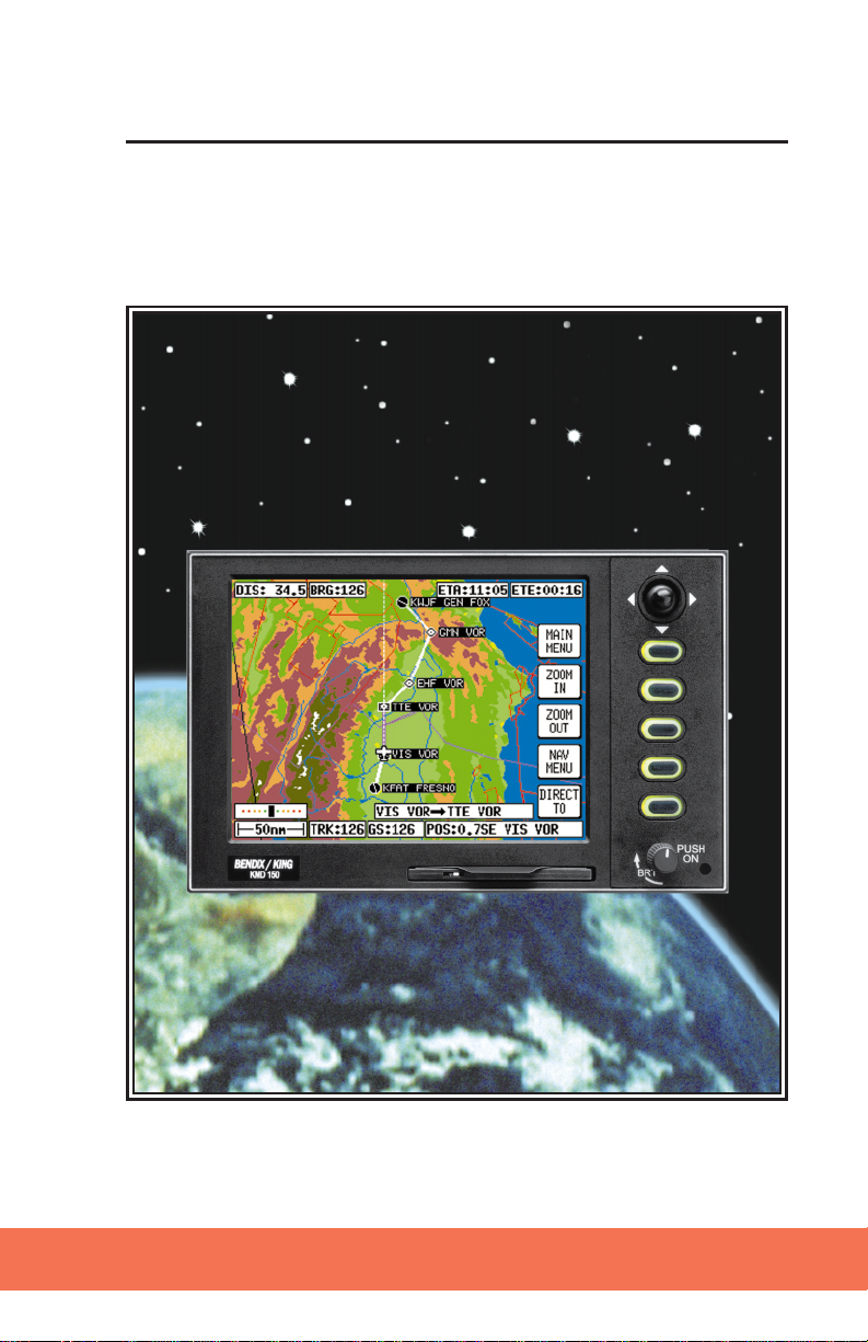
KMD 150
Multifunction Display/GPS
Pilot’s Guide
Rev 1 Mar/2000
006-18220-0000
Software Revision 1.10 or Higher
N

The information contained in this manual is for reference use only. If
any information contained herein conflicts with similar information
contained in the Airplane Flight Manual Supplement, the information in
the Airplane Flight Manual Supplement shall take precedence.
WARNING
Prior to export of this document, review for export license requirement is
needed.
COPYRIGHT NOTICE
©2000 Honeywell International Inc.
Reproduction of this publication or any portion thereof by any means without
the express written permission of Honeywell International Inc. is prohibited.
For further information contact the Manager, Technical Publications;
Honeywell Business & General Aviation; One Technology Center; 23500
West 105th Street; Olathe, Kansas 66061. Telephone: (913) 782-0400.

Table of Contents
INTRODUCTION . . . . . . . . . . . . . . . . . . . . . . . . . . . . . . . . . . . . . . . . . . . . . . .1
DEFINITIONS, ACRONYMS AND ABBREVIATIONS . . . . . . . . . . . . . . . .2
Definitions . . . . . . . . . . . . . . . . . . . . . . . . . . . . . . . . . . . . . . . . . . . . .2
Acronyms and Abbreviations. . . . . . . . . . . . . . . . . . . . . . . . . . . . . . .4
GENERAL INFORMATION . . . . . . . . . . . . . . . . . . . . . . . . . . . . . . . . . . . . .9
SOFT KEYING . . . . . . . . . . . . . . . . . . . . . . . . . . . . . . . . . . . . . . . . . . . .10
SELECTABLE GPS DATA SOURCE . . . . . . . . . . . . . . . . . . . . . . . . . . . .10
STORMSCOPE OPTION . . . . . . . . . . . . . . . . . . . . . . . . . . . . . . . . . . . .11
SOFTWARE ARCHITECTURE . . . . . . . . . . . . . . . . . . . . . . . . . . . . . . . .11
SCREEN ICONS . . . . . . . . . . . . . . . . . . . . . . . . . . . . . . . . . . . . . . . . . .14
OBSTACLE LABELS . . . . . . . . . . . . . . . . . . . . . . . . . . . . . . . . . . . . . . .14
TERRAIN AND URBAN AREAS DISPLAY . . . . . . . . . . . . . . . . . . . . . . .14
MEMORY LOCATIONS . . . . . . . . . . . . . . . . . . . . . . . . . . . . . . . . . . . . .15
GETTING STARTED . . . . . . . . . . . . . . . . . . . . . . . . . . . . . . . . . . . . . . . . .17
INTRODUCTION . . . . . . . . . . . . . . . . . . . . . . . . . . . . . . . . . . . . . . . . . .17
INITIALIZING YOUR UNIT . . . . . . . . . . . . . . . . . . . . . . . . . . . . . . . . . .17
SOFTWARE STRUCTURE . . . . . . . . . . . . . . . . . . . . . . . . . . . . . . . . . . .18
SELECTING DEMO MODE . . . . . . . . . . . . . . . . . . . . . . . . . . . . . . . . . .19
DATABASE SELECTION . . . . . . . . . . . . . . . . . . . . . . . . . . . . . . . . . . . .20
A QUICK WORD ON DIRECT TOS AND FLIGHT PLANS . . . . . . . . . . . .20
VISUAL DIRECT TO AND DATA INTERROGATION . . . . . . . . . . . . . . . .21
DIRECT TO A SPECIFIC LATITUDE AND LONGITUDE . . . . . . . . . . . . .21
MANUAL DIRECT TO AND DATA INTERROGATION . . . . . . . . . . . . . . .22
EDITING/CREATING A USER WAYPOINT MANUALLY . . . . . . . . . . . . .22
EDITING/CREATING A USER WAYPOINT VISUALLY . . . . . . . . . . . . . .23
SAVING A USER WAYPOINT IN FLIGHT . . . . . . . . . . . . . . . . . . . . . . .23
SELECTING STORMSCOPE MODE . . . . . . . . . . . . . . . . . . . . . . . . . . . .24
Rev 1 Mar/2000
i
KMD 150 Pilot's Guide

Table of Contents
EDITING/CREATING A FLIGHT PLAN MANUALLY . . . . . . . . . . . . . . . .24
EDITING/CREATING A FLIGHT PLAN VISUALLY . . . . . . . . . . . . . . . . .25
SELECTING A FLIGHT PLAN TO FLY . . . . . . . . . . . . . . . . . . . . . . . . . .26
SELECTING A MAP MODE . . . . . . . . . . . . . . . . . . . . . . . . . . . . . . . . . .26
VIEWING ETAS, DIRECT-TO ON FLIGHT PLAN . . . . . . . . . . . . . . . . . .27
TEN NEAREST SEARCH . . . . . . . . . . . . . . . . . . . . . . . . . . . . . . . . . . . .27
SETUP MAP FUNCTIONS . . . . . . . . . . . . . . . . . . . . . . . . . . . . . . . . . . .28
SETUP OF NAVIGATION FUNCTIONS . . . . . . . . . . . . . . . . . . . . . . . . . .30
CLEAR MEMORY . . . . . . . . . . . . . . . . . . . . . . . . . . . . . . . . . . . . . . . . .31
TITLE AND HELP SCREENS . . . . . . . . . . . . . . . . . . . . . . . . . . . . . . . . . . .33
SELF TEST AND INITIALIZATION . . . . . . . . . . . . . . . . . . . . . . . . . . . . .34
MAIN MENU SCREEN . . . . . . . . . . . . . . . . . . . . . . . . . . . . . . . . . . . . .35
NOTE PAD SCREEN . . . . . . . . . . . . . . . . . . . . . . . . . . . . . . . . . . . . . . .35
GPS STATUS SCREENS . . . . . . . . . . . . . . . . . . . . . . . . . . . . . . . . . . . . . .37
ADJUSTING TIME AND DATE . . . . . . . . . . . . . . . . . . . . . . . . . . . . . . .40
SETTING LOCAL TIME OFFSET . . . . . . . . . . . . . . . . . . . . . . . . . . . . . .40
SETTING PRESENT POSITION . . . . . . . . . . . . . . . . . . . . . . . . . . . . . . .41
DATA INPUT (EXTERNAL GPS MODE) . . . . . . . . . . . . . . . . . . . . . . . . . . .43
DISPLAY OF HOST FLIGHT PLAN DATA . . . . . . . . . . . . . . . . . . . . . . .43
Bendix/King Data Format . . . . . . . . . . . . . . . . . . . . . . . . . . . . . . . . .43
NMEA and Northstar data . . . . . . . . . . . . . . . . . . . . . . . . . . . . . . . .44
FLIGHT PLANNING SCREENS . . . . . . . . . . . . . . . . . . . . . . . . . . . . . . . . .45
USER WAYPOINTS . . . . . . . . . . . . . . . . . . . . . . . . . . . . . . . . . . . . . . .45
Basic User Waypoints . . . . . . . . . . . . . . . . . . . . . . . . . . . . . . . . . . .45
Marker User Waypoints . . . . . . . . . . . . . . . . . . . . . . . . . . . . . . . . . .45
User Defined Airports . . . . . . . . . . . . . . . . . . . . . . . . . . . . . . . . . . . .46
VIEWING USER WAYPOINTS . . . . . . . . . . . . . . . . . . . . . . . . . . . . . . . .47
Rev 1 Mar/2000
ii
KMD 150 Pilot's Guide

Table of Contents
MANUAL USER WAYPOINT EDITING . . . . . . . . . . . . . . . . . . . . . . . . .48
GRAPHICAL USER WAYPOINT EDITING . . . . . . . . . . . . . . . . . . . . . . .49
EDITING USER AIRPORTS . . . . . . . . . . . . . . . . . . . . . . . . . . . . . . . . . .50
FLIGHT PLANS . . . . . . . . . . . . . . . . . . . . . . . . . . . . . . . . . . . . . . . . . . .50
MANUAL FLIGHT PLAN BUILDING AND EDITING . . . . . . . . . . . . . . . .51
MANUALLY INSERTING A WAYPOINT INTO A FLIGHT PLAN AND
MANUAL DIRECT TO . . . . . . . . . . . . . . . . . . . . . . . . . . . . . . . . . . . . . .53
Selecting Data Source . . . . . . . . . . . . . . . . . . . . . . . . . . . . . . . . . . .53
Selecting Item From Chosen Database . . . . . . . . . . . . . . . . . . . . . . .54
GRAPHICAL VIEWING AND EDITING OF FLIGHT PLANS . . . . . . . . . . .56
MAP MODE SCREENS . . . . . . . . . . . . . . . . . . . . . . . . . . . . . . . . . . . . . . .59
DATA INTERROGATION AND GRAPHICAL DIRECT TO . . . . . . . . . . . .61
Airport Information . . . . . . . . . . . . . . . . . . . . . . . . . . . . . . . . . . . . .62
Navaid Information . . . . . . . . . . . . . . . . . . . . . . . . . . . . . . . . . . . . .62
General Icon Information . . . . . . . . . . . . . . . . . . . . . . . . . . . . . . . . .63
Airspace Interrogation . . . . . . . . . . . . . . . . . . . . . . . . . . . . . . . . . . .63
NAV MENU SCREENS . . . . . . . . . . . . . . . . . . . . . . . . . . . . . . . . . . . . . . .65
SELECTING A FLIGHT PLAN . . . . . . . . . . . . . . . . . . . . . . . . . . . . . . . .67
TEN NEAREST AIRPORTS . . . . . . . . . . . . . . . . . . . . . . . . . . . . . . . . . .68
NAVAIDS . . . . . . . . . . . . . . . . . . . . . . . . . . . . . . . . . . . . . . . . . . . . . . .70
MAP MODE WITH NAV INFORMATION . . . . . . . . . . . . . . . . . . . . . . . . . .73
VIEWING ENROUTE ETA'S, PERFORMING A DIRECT-TO ON TOP
OF FLIGHT PLAN . . . . . . . . . . . . . . . . . . . . . . . . . . . . . . . . . . . . . . . . .75
Performing A Direct-To On Top of A Flight Plan . . . . . . . . . . . . . . . .75
Performing a DIRECT TO a point not in the active Flight Plan. . . . . .75
ARRIVAL AT AN ENROUTE USER WAYPOINT . . . . . . . . . . . . . . . . . . .76
ARRIVAL AT YOUR FINAL DESTINATION . . . . . . . . . . . . . . . . . . . . . .77
Rev 1 Mar/2000
iii
KMD 150 Pilot's Guide

Table of Contents
ALTERNATIVE MAP MODES . . . . . . . . . . . . . . . . . . . . . . . . . . . . . . . .78
Large Text Mode . . . . . . . . . . . . . . . . . . . . . . . . . . . . . . . . . . . . . . .78
CDI Mode . . . . . . . . . . . . . . . . . . . . . . . . . . . . . . . . . . . . . . . . . . . . .78
E6-B CALCULATOR . . . . . . . . . . . . . . . . . . . . . . . . . . . . . . . . . . . . . . . . .81
DENSITY ALTITUDE/TAS/WINDS ALOFT CALCULATOR . . . . . . . . . . .81
To Calculate Density Altitude (DALT) and True Airspeed (TAS) . . . .81
To Calculate Winds Aloft (WIND) and Headwind/Tailwind
Component (COMP) . . . . . . . . . . . . . . . . . . . . . . . . . . . . . . . . . . . . .82
VERTICAL NAVIGATION (VNAV) . . . . . . . . . . . . . . . . . . . . . . . . . . . . .82
TRIP/FUEL PLANNING . . . . . . . . . . . . . . . . . . . . . . . . . . . . . . . . . . . . .84
SUNSET/SUNRISE CALCULATOR . . . . . . . . . . . . . . . . . . . . . . . . . . . .86
SETUP SCREENS . . . . . . . . . . . . . . . . . . . . . . . . . . . . . . . . . . . . . . . . . . .87
MAP SETUP SCREENS . . . . . . . . . . . . . . . . . . . . . . . . . . . . . . . . . . . .87
Settings Available . . . . . . . . . . . . . . . . . . . . . . . . . . . . . . . . . . . . . . .88
NAV MODE SETUP . . . . . . . . . . . . . . . . . . . . . . . . . . . . . . . . . . . . . . . .92
PERSONAL IDENTIFICATION NUMBER (PIN) SETUP . . . . . . . . . . . . .94
Auto Power-On Lock . . . . . . . . . . . . . . . . . . . . . . . . . . . . . . . . . . . .96
INSTALLATION AND DIAGNOSTIC SCREENS . . . . . . . . . . . . . . . . . . .97
Screen Position Setup . . . . . . . . . . . . . . . . . . . . . . . . . . . . . . . . . . .97
View Logs . . . . . . . . . . . . . . . . . . . . . . . . . . . . . . . . . . . . . . . . . . . .98
Engineering Log . . . . . . . . . . . . . . . . . . . . . . . . . . . . . . . . . . . . . .98
GPS Receiver Information Log . . . . . . . . . . . . . . . . . . . . . . . . . . .98
Clear Memory . . . . . . . . . . . . . . . . . . . . . . . . . . . . . . . . . . . . . . . . .99
Data In/Out . . . . . . . . . . . . . . . . . . . . . . . . . . . . . . . . . . . . . . . . . . .100
External GPS Data Input Option . . . . . . . . . . . . . . . . . . . . . . . . . . .101
Output Test . . . . . . . . . . . . . . . . . . . . . . . . . . . . . . . . . . . . . . . . . .102
Rev 1 Mar/2000
iv
KMD 150 Pilot's Guide

Table of Contents
STORMSCOPE OPERATION . . . . . . . . . . . . . . . . . . . . . . . . . . . . . . . . . .105
INTRODUCTION . . . . . . . . . . . . . . . . . . . . . . . . . . . . . . . . . . . . . . . . .105
FUNCTIONAL DESCRIPTION . . . . . . . . . . . . . . . . . . . . . . . . . . . . . . .105
Cell Display Mode . . . . . . . . . . . . . . . . . . . . . . . . . . . . . . . . . . . . .106
Strike Display Mode . . . . . . . . . . . . . . . . . . . . . . . . . . . . . . . . . . . .106
STORMSCOPE MODE FEATURES . . . . . . . . . . . . . . . . . . . . . . . . . . .106
ANATOMY OF A THUNDERSTORM . . . . . . . . . . . . . . . . . . . . . . . . . .107
Stages of a Thunderstorm . . . . . . . . . . . . . . . . . . . . . . . . . . . . . . .108
Cumulus Stage . . . . . . . . . . . . . . . . . . . . . . . . . . . . . . . . . . . . . . . .108
Mature Stage . . . . . . . . . . . . . . . . . . . . . . . . . . . . . . . . . . . . . . . . .109
Dissipating Stage . . . . . . . . . . . . . . . . . . . . . . . . . . . . . . . . . . . . . .109
THE WX-500 AND WEATHER RADAR . . . . . . . . . . . . . . . . . . . . . . . .109
OPERATION . . . . . . . . . . . . . . . . . . . . . . . . . . . . . . . . . . . . . . . . . . . .110
Power-up . . . . . . . . . . . . . . . . . . . . . . . . . . . . . . . . . . . . . . . . . . . .110
Continuous and Operator-initiated Self Test . . . . . . . . . . . . . . . . . .110
Heading Stabilization . . . . . . . . . . . . . . . . . . . . . . . . . . . . . . . . . . .110
Clear all Discharge Points . . . . . . . . . . . . . . . . . . . . . . . . . . . . . . .111
Switch Between Weather Views . . . . . . . . . . . . . . . . . . . . . . . . . . .111
Switch Between WX Display Modes . . . . . . . . . . . . . . . . . . . . . . . .111
Changing Display Range . . . . . . . . . . . . . . . . . . . . . . . . . . . . . . . .111
Operation in Stormscope Mode with Nav Overlay . . . . . . . . . . . . .112
Operation in Map Mode . . . . . . . . . . . . . . . . . . . . . . . . . . . . . . . . .112
Error Messages . . . . . . . . . . . . . . . . . . . . . . . . . . . . . . . . . . . . . . .113
Non-Fatal Faults . . . . . . . . . . . . . . . . . . . . . . . . . . . . . . . . . . . . .114
Recoverable Faults . . . . . . . . . . . . . . . . . . . . . . . . . . . . . . . . . . .114
Heading Related Faults . . . . . . . . . . . . . . . . . . . . . . . . . . . . . . . .114
Non-Recoverable Faults . . . . . . . . . . . . . . . . . . . . . . . . . . . . . . .114
Fatal Faults . . . . . . . . . . . . . . . . . . . . . . . . . . . . . . . . . . . . . . . . .114
Rev 1 Mar/2000
v
KMD 150 Pilot's Guide

Table of Contents
WEATHER DISPLAY INTERPRETATION . . . . . . . . . . . . . . . . . . . . . . .115
Introduction . . . . . . . . . . . . . . . . . . . . . . . . . . . . . . . . . . . . . . . . . .115
Radial Spread . . . . . . . . . . . . . . . . . . . . . . . . . . . . . . . . . . . . . . . . .116
Typical Patterns . . . . . . . . . . . . . . . . . . . . . . . . . . . . . . . . . . . . . . .116
Three Clusters Within the 200nm Range Ring . . . . . . . . . . . . . .116
Two Clusters Within the 200nm Range Ring . . . . . . . . . . . . . . .119
Mapping Headings Past Thunderstorms . . . . . . . . . . . . . . . . . . . .120
Range Set at 200nm . . . . . . . . . . . . . . . . . . . . . . . . . . . . . . . . .120
Aircraft Progresses 100nm . . . . . . . . . . . . . . . . . . . . . . . . . . . .121
Range Changes to 100nm . . . . . . . . . . . . . . . . . . . . . . . . . . . . .122
Aircraft Turns to Avoid Thunderstorms . . . . . . . . . . . . . . . . . . .123
Special Patterns . . . . . . . . . . . . . . . . . . . . . . . . . . . . . . . . . . . . . . .124
Randomly Scattered Discharge Points . . . . . . . . . . . . . . . . . . . .124
Cluster and Splattering Within 25nm . . . . . . . . . . . . . . . . . . . . .125
Discharge Points Off Aircraft’s Nose . . . . . . . . . . . . . . . . . . . . .126
Line of Discharge Points While Taxiing . . . . . . . . . . . . . . . . . . .127
Developing Cluster Within the 25nm Range Ring . . . . . . . . . . .128
DEMO MODE . . . . . . . . . . . . . . . . . . . . . . . . . . . . . . . . . . . . . . . . . . . . .129
STORMSCOPE DEMO MODE . . . . . . . . . . . . . . . . . . . . . . . . . . . . . . .130
APPENDIX 1 - WARNING SCREENS . . . . . . . . . . . . . . . . . . . . . . . . . . .131
RAM LOST WARNING . . . . . . . . . . . . . . . . . . . . . . . . . . . . . . . . . . . .131
MEMORY BATTERY WARNING . . . . . . . . . . . . . . . . . . . . . . . . . . . . .131
PIN LOCK WARNING . . . . . . . . . . . . . . . . . . . . . . . . . . . . . . . . . . . . .132
LOCK OUT WARNING . . . . . . . . . . . . . . . . . . . . . . . . . . . . . . . . . . . .132
NEW DATABASE CARD WARNING . . . . . . . . . . . . . . . . . . . . . . . . . .133
Rev 1 Mar/2000
vi
KMD 150 Pilot's Guide

Table of Contents
APPENDIX 2 - DATABASE CARDS . . . . . . . . . . . . . . . . . . . . . . . . . . . . .135
DATA AREAS . . . . . . . . . . . . . . . . . . . . . . . . . . . . . . . . . . . . . . . . . . .135
CHANGING THE DATABASE CARD . . . . . . . . . . . . . . . . . . . . . . . . . .136
MINIMUM SAFE ALTITUDES (MSA) . . . . . . . . . . . . . . . . . . . . . . . . .136
Flight Plan Building . . . . . . . . . . . . . . . . . . . . . . . . . . . . . . . . . . . .136
During Flight . . . . . . . . . . . . . . . . . . . . . . . . . . . . . . . . . . . . . . . . .137
WORLD-WIDE ICAO CODES . . . . . . . . . . . . . . . . . . . . . . . . . . . . . . .137
APPENDIX 3 - HOW DOES GPS WORK? . . . . . . . . . . . . . . . . . . . . . . . .147
WHAT IS GPS? . . . . . . . . . . . . . . . . . . . . . . . . . . . . . . . . . . . . . . . . .147
HOW DOES GPS WORK? . . . . . . . . . . . . . . . . . . . . . . . . . . . . . . . . . .147
ACCURACY AND RELIABILITY . . . . . . . . . . . . . . . . . . . . . . . . . . . . . .149
APPENDIX 4 - DIFFERENTIAL FUNCTIONS . . . . . . . . . . . . . . . . . . . . . .151
WHAT IS DGPS? . . . . . . . . . . . . . . . . . . . . . . . . . . . . . . . . . . . . . . . .151
HOW DOES DGPS WORK? . . . . . . . . . . . . . . . . . . . . . . . . . . . . . . . .151
USE OF DGPS . . . . . . . . . . . . . . . . . . . . . . . . . . . . . . . . . . . . . . . . . .152
APPENDIX 5 - DATABASE INFORMATION . . . . . . . . . . . . . . . . . . . . . . .153
DATABASE CYCLE INFORMATION . . . . . . . . . . . . . . . . . . . . . . . . . . .153
Rev 1 Mar/2000
vii
KMD 150 Pilot's Guide

Table of Contents
Intentionally left blank
Rev 1 Mar/2000
viii
KMD 150 Pilot's Guide

Table of Contents
SCREEN INDEX
Screen 1: Title Screen . . . . . . . . . . . . . . . . . . . . . . . . . . . . . . . . . . . . . . .33
Screen 2: Main Menu Screen . . . . . . . . . . . . . . . . . . . . . . . . . . . . . . . . .35
Screen 3: GPS Status Screen . . . . . . . . . . . . . . . . . . . . . . . . . . . . . . . . .37
Screen 4: Date and Time Adjustment Screen . . . . . . . . . . . . . . . . . . . . .40
Screen 5: Local Time Offset Screen . . . . . . . . . . . . . . . . . . . . . . . . . . . .40
Screen 6: Present Position Setup Screen . . . . . . . . . . . . . . . . . . . . . . . .41
Screen 7: Flight Planning Mode Cover Screen . . . . . . . . . . . . . . . . . . . .47
Screen 8: User Waypoint Viewer Screen . . . . . . . . . . . . . . . . . . . . . . . . .47
Screen 8A: User Airfield Edit Screen . . . . . . . . . . . . . . . . . . . . . . . . . . . .50
Screen 9: Manual User Waypoint Edit Screen . . . . . . . . . . . . . . . . . . . . .48
Screen 10: View and Edit User Waypoints on the Map Screen . . . . . . . .49
Screen 10A: View Map Screen . . . . . . . . . . . . . . . . . . . . . . . . . . . . . . . .41
Screen 11: Flight Plan Selection Screen . . . . . . . . . . . . . . . . . . . . . . . . .50
Screen 12: Flight Plan Program/Edit Screen . . . . . . . . . . . . . . . . . . .51, 68
Screen 13: Database Selection Screen . . . . . . . . . . . . . . . . . . . . . . . . . .53
Screen 15: Temporary Waypoint Input Screen . . . . . . . . . . . . . . . . . . . .54
Screen 16: Item Selection Screen . . . . . . . . . . . . . . . . . . . . . . . . . . . . . .54
Screen 19: View and Edit Flight Plans On Map Screen . . . . . . . . . . . . . .56
Screen 20: Demo Mode Setup Screen . . . . . . . . . . . . . . . . . . . . . . . . .129
Screen 21: Setup Cover Screen . . . . . . . . . . . . . . . . . . . . . . . . . . . . . . . .87
Screen 22 : Map Customization Screen . . . . . . . . . . . . . . . . . . . . . . . . . .87
Screen 22A: Point Features Data Class Setup Screen . . . . . . . . . . . . . . .90
Screen 22B: Line Features Data Class Setup Screen. . . . . . . . . . . . . . . .91
Screen 22C: Airspace Data Class Setup Screen . . . . . . . . . . . . . . . . . . .91
Screen 23: NAV Mode Customization Screen . . . . . . . . . . . . . . . . . . . . .92
Screen 24: PIN Setup Cover Screen . . . . . . . . . . . . . . . . . . . . . . . . . . . .94
Rev 1 Mar/2000
ix
KMD 150 Pilot's Guide

Table of Contents
Screen 25: PIN Incorrect Screen . . . . . . . . . . . . . . . . . . . . . . . . . . . . . . .94
Screen 26: PIN Change & Power-On Lock Enable Screen . . . . . . . . . . . .95
Screen 27: PIN Change Screen . . . . . . . . . . . . . . . . . . . . . . . . . . . . . . . .95
Screen 28: Installation and Diagnostics Cover Screen . . . . . . . . . . . . . .97
Screen 30: Engineering Log Screen . . . . . . . . . . . . . . . . . . . . . . . . . . . .98
Screen 31: GPS Receiver Information Screen (Internal GPS Units Only) 98
Screen 32: Memory Clear Entry Screen . . . . . . . . . . . . . . . . . . . . . . . . .99
Screen 33: Memory Clear Cover Screen . . . . . . . . . . . . . . . . . . . . . . . . .99
Screen 35: Data Input/Output Setup and Test Screen . . . . . . . . . . . . . .100
Screen 35B: GPS Source Change Warning Screen . . . . . . . . . . . . . . . .101
Screen 37: Aviation Interface Output Test Screen . . . . . . . . . . . . . . . . .102
Screen 38: Basic Map Mode Screen . . . . . . . . . . . . . . . . . . . . . . . . . . . .59
Screen 39: Map Mode with Joystick Active Screen . . . . . . . . . . . . . . . . .61
Screen 40: Map Mode Airport Info Screen . . . . . . . . . . . . . . . . . . . . . . .62
Screen 40A: Map Mode Navaid Information Screen . . . . . . . . . . . . . . . .62
Screen 40B: Airspace Information Screen . . . . . . . . . . . . . . . . . . . . . . .64
Screen 40C: Map Mode General Information Screen . . . . . . . . . . . . . . .63
Screen 41: NAV Menu Cover Screen . . . . . . . . . . . . . . . . . . . . . . . . . . . .65
Screen 41A: View ETA's and Direct-To Screen. . . . . . . . . . . . . . . . . . . . .75
Screen 42: Flight Plan Selection Screen . . . . . . . . . . . . . . . . . . . . . . . . .67
Screen 43: Ten Nearest Airfields Screen . . . . . . . . . . . . . . . . . . . . . . . . .68
Screen 44: Airport Information Screen . . . . . . . . . . . . . . . . . . . . . . . . . .69
Screen 45: Ten Nearest Navaids Screen . . . . . . . . . . . . . . . . . . . . . . . . .70
Screen 46: Navaid Information Screen . . . . . . . . . . . . . . . . . . . . . . . . . .70
Screen 47: Map Mode with NAV Information Screen . . . . . . . . . . . . . . .73
Screen 47A: Large Text & Map NAV Information Screen. . . . . . . . . . . . .78
Screen 47B: Large Text & CDI (Pseudo HSI) NAV Information Screen . .78
Rev 1 Mar/2000
x
KMD 150 Pilot's Guide

Table of Contents
Screen 48: NAV Information and WTP IMMINENT Flags Showing -
Enroute Screen . . . . . . . . . . . . . . . . . . . . . . . . . . . . . . . . . . .76
Screen 49: NAV Information and TP IMMINENT Flags Showing -
Final Screen . . . . . . . . . . . . . . . . . . . . . . . . . . . . . . . . . . . . .77
Screen 50: Representation of Screen 47 Showing DEMO MODE Flag . .130
Screen 51: RAM Lost Warning Screen . . . . . . . . . . . . . . . . . . . . . . . . .131
Screen 52: Memory Battery Warning Screen . . . . . . . . . . . . . . . . . . . .131
Screen 54: Power On Security PIN Entry Screen . . . . . . . . . . . . . . . . .132
Screen 55: Lockout Screen . . . . . . . . . . . . . . . . . . . . . . . . . . . . . . . . .132
Screen 56: Flight Plan Change Warning Screen . . . . . . . . . . . . . . . . . .133
Screen 57: E6-B Calculator Cover Screen . . . . . . . . . . . . . . . . . . . . . . . .81
Screen 58: Density Altitude, True Air Speed & Winds Aloft Screen . . . . .81
Screen 59: VNAV Setup Screen . . . . . . . . . . . . . . . . . . . . . . . . . . . . . . . .83
Screen 60: Trip / Fuel Flight Plan Select Screen . . . . . . . . . . . . . . . . . . .85
Screen 61: Sunset/Sunrise Calculator Screen . . . . . . . . . . . . . . . . . . . . .86
Screen 62: Notepad Screen . . . . . . . . . . . . . . . . . . . . . . . . . . . . . . . . . . .35
Rev 1 Mar/2000
xi
KMD 150 Pilot's Guide

Table of Contents
Intentionally left blank
Rev 1 Mar/2000
xii
KMD 150 Pilot's Guide

Introduction
INTRODUCTION
All of us at Honeywell congratulate you on choosing this product. You
are now the owner of one of the most sophisticated yet simple-to-use
Navaids available today. We understand you probably can’t wait to see
it in action but before you try to use it do please take the time to read
through this manual and understand its many interesting and useful features. Time spent in familiarizing yourself with your new KMD 150 unit
will be more than repaid by trouble-free operation later, and more importantly safe and accurate navigation.
We have made the operation of this unit as intuitive as possible through
the use of soft keying and on-screen help, thus reducing pilots’ dependence on the manual. You should very quickly find that handling it efficiently and expertly becomes second nature to you. Don’t be afraid to
experiment. No matter which key you activate, your unit will not be damaged. If you do get into a mess, simply switch off and back on again to
reset all functions. We must mention just one word of caution. Never
remove the database card while the unit is switched on and never
attempt to switch the unit on when there is no database card
installed.
We thank you for your decision to purchase a KMD 150 and wish you
many happy and safe hours flying.
WARNING
The Global Positioning System (GPS) satellite constellation is operated by the Department of Defense (DOD) of the United States,
which is solely responsible for its accuracy and maintenance.
Although declared fully operational on July 17, 1995, the system is
still under development and subject to changes that could affect
the accuracy and performance of all GPS equipment.
Use this equipment at your own risk. Your new KMD 150 unit is a
precision navigation aid but like any navaid it can be misused or
misinterpreted and so become unsafe. You are strongly advised to
read and fully understand this manual before using the equipment.
If your unit has an internal GPS then a DEMO MODE or simulation
facility exists that allows you to practice with it before you begin
using it for actual navigation.
Whenever you are using the unit for navigation in the air you should treat
it as a supplemental navigation system. You should always carefully
compare indications from your KMD 150 unit with the information available from all other navigation sources including NDBs, VORs, DMEs,
visual sightings, charts, etc. For safety, any discrepancies observed
should be resolved immediately.
Rev 1 Mar/2000 KMD 150 Pilot's Guide
1

Introduction
The altitude calculated by GPS equipment is geometric height above a
theoretical mean sea level of a mathematically calculated ellipsoid that
approximates to the shape of the earth. This altitude can differ significantly from that displayed by your pressure altimeter. You must therefore, NEVER USE GPS ALTITUDE FOR VERTICAL NAVIGATION OR
TERRAIN AVOIDANCE.
This equipment is not a replacement for your chart. It is intended as an
aid to navigation only. The database within the equipment has been
compiled from the latest official information available, and although every
care has been taken in the compilation, the manufacturers will not be
held responsible for any inaccuracy or omissions therein. NEVER USE
THE TERRAIN DISPLAYED ON THIS EQUIPMENT AS YOUR SOLE
REFERENCE FOR TERRAIN AVOIDANCE.
DEFINITIONS, ACRONYMS AND ABBREVIATIONS
DEFINITIONS
Alphabetic: any of the following characters (b/ is a space): b/ABCDE-
FGHIJKLMNOPQRSTUVWXYZ
Alphanumeric: any of the following characters (b/ is a space):
b/ABCDEFGHIJKLMNOPQRSTUVWXYZ0123456789
Baud: bits per sec
Barometric Altitude: pressure altitude corrected for barometric
altimeter setting
Bearing To User Waypoint: bearing from the present position to the
active user waypoint measured clockwise relative to true or magnetic
north (true is implied unless magnetic is specified)
Cross Track Error: distance from the present position to the nearest
point on the desired course, and the direction (right or left) from the
desired course to the present position
Cursor Field: a character position or group of adjacent character positions on which a cursor can appear
Data Entry Field: A data entry field is an enterable data field where the
ENTER, SET or SELECT button must be pressed before data entered in
the field becomes effective. A data entry field can be a single or multiple
character cursor field. During data entry, the active cursor field remains
reverse video.
Data Field: a character position or group of adjacent character positions
which display a single data item; a data field may be a single character
cursor field, or may contain multiple characters.
Rev 1 Mar/2000
2
KMD 150 Pilot's Guide

Introduction
Data List: an ordered list of data elements which a given cursor field
can accept
Desired Track: The angle that the desired flight path makes with
respect to true north at the point nearest the present position. Magnetic
desired track uses the local magnetic variation.
Destination: If the active user waypoint is not in the active flight plan,
the active user waypoint is the destination. If the active user waypoint is
in the active flight plan, the final user waypoint in the flight plan is the
destination.
Distance To Waypoint (DIS): distance from the present position to the
active waypoint
Enroute Safe Altitude: the highest minimum safe altitude which will be
encountered for a given flight path (present position to destination, via
flight plan if appropriate; or a flight path being analyzed by trip planning)
Flashing: active for .75 sec (.05 sec, inactive for .25 sec (.05 sec
Ground Speed: absolute value of the rate of change of position
Headwind: difference between true airspeed and ground speed when
true airspeed is more than ground speed
Knots: Nautical Miles/hr
Minimum Safe Altitude: Minimum safe altitude is the highest minimum
off route altitude for any sector within a 10 nm square centered at a given
position. A minimum off route altitude of 7000 feet or less clears all
known obstructions and terrain in a sector by 1000 feet; a minimum off
route altitude greater than 7000 feet clears all terrain by 2000 feet. A
sector is an area bounded by a 1o latitude/longitude grid.
Scrolling Region: a set of consecutive cursor fields which display a
portion of a scroll list; “scroll up” means that the data item in each cursor
field in the scrolling region moves to the preceding cursor field. The data
item in the first cursor field disappears from the page, and the last cursor
field displays the next item in the scroll list; “scroll down” is the opposite.
If there is other data associated with the data in the cursor fields (such as
user waypoint numbers in flight plans), it also moves.
Selected Course: The angle that the desired flight path makes with
respect to true north at the active user waypoint. Magnetic selected
course uses the magnetic variation at the active user waypoint; if the
active user waypoint is a VOR, the magnetic variation stored for that
VOR is used.
Special Use Airspace: any of the following: prohibited area, restricted
area, warning area, alert area, MOA, Class CARSA, Class BTCA,
unknown, danger, caution, training, CTA, or TMA type
Rev 1 Mar/2000 KMD 150 Pilot's Guide
3

Introduction
Standard Rate Turn: 3°/sec
Tailwind: difference between ground speed and true airspeed when
ground speed is more than true airspeed
Terminal User Waypoints: user waypoints that are duplicated within a
country code or “unnamed” user waypoints associated with an approach
that are assigned to distinct airports
Time To User Waypoint: distance to user waypoint divided by ground
speed
Track: angle of the aircraft’s path over the ground measured clockwise
relative to true or magnetic north (true is implied unless magnetic is
specified).
ACRONYMS AND ABBREVIATIONS
AC: Alternating Current
ACT: Active (user waypoint or flight plan)
ADF: Automatic Direction Finder
AGL: Above Ground Level
ANSI: American National Standards Institute
APT: Airport
ARTCC: Air Route Traffic Control Center
ASCII: American Standard Code for Information
Interchange
ATC: Air Traffic Control
ATF: Aerodrome Traffic Frequency
ATIS: Automatic Terminal Information Service
A/C: Aircraft
baud: or Baud Rate; a measurement of data transmission
speed
BRG: Bearing
CAA: Civil Aviation Authority
CAS: Calibrated Airspeed
com: communication
CDI: Course Deviation Indicator
Rev 1 Mar/2000
4
KMD 150 Pilot's Guide

CTA: Control Area
CTAF: Common Traffic Advisory Frequency
CTR: Control Zone
CTZ: Control Tower Zone
CWI: Continuous Wave Interference
dB: decibels
DC: Direct Current
DIS: Distance
DME: Distance Measuring Equipment
DOT: United States Department of Transportation
EFIS: Electronic Flight Instrument System
ELT: Emergency Locator Transmitter
ESA: Enroute Safe Altitude
ETE: Estimated Time Enroute
FAA: Federal Aviation Administration
Introduction
FAR: Federal Aviation Regulations
FPL: Flight Plan
FPM: Feet Per Minute
FSS: Flight Service Station
ft: feet
FT: Feet
G: Gravitational Acceleration = 32.2 ft/sec2 = 19.3
kt/sec2
GAL: Gallons
GPS: Global Positioning System
hr: hour
HSI: Horizontal Situation Indicator
Hz: Hertz
IAF: Initial Approach Fix
IAP: Instrument Approach Procedure
Rev 1 Mar/2000 KMD 150 Pilot's Guide
5

Introduction
IEEE: Institute of Electrical and Electronics Engineering
IFR: Instrument Flight Rules
in.: inches
INT: Intersection
kHz: kilohertz
Kt.: Knots
KΩ: Kilohms
LAT: Latitude
LB: Pounds
LED: Light Emitting Diode
LON: Longitude
LONG: Longitude
LRU: Line Replaceable Unit
m: meters
mA: milliamperes
MATZ: Military Air Traffic Zone
MAHP: Missed Approach Holding Point
MAP: Missed Approach Point
mB: millibars
MF: Mandatory Frequency
MHz: Megahertz
mi: statute miles
min: minutes
MOA: Military Operation Area
MSA: Minimum Safe Altitude
MSL: Mean Sea Level
msec: milliseconds
NDB: Non-Directional Beacon
nm: Nautical Miles
NPA: Non Precision Approach
Rev 1 Mar/2000
6
KMD 150 Pilot's Guide

NVM: Non Volatile Memory
OBI: Omni-directional Bearing Indicator
OBS: Omni-directional Bearing Selector
PETE: Pointer ETE
PIN: Personal Identification Number
RAD: Radial
REF: Reference
RMI: Radio Magnetic Indicator
RTCA: Radio Technical Commission for Aeronautics
SA: Selective Availability (intentional errors introduced
by the DOD)
SAT: Static Air Temperature
sec: seconds
SID: Standard Instrument Departure
SNR: Signal to Noise Ratio
STAR: Standard Terminal Arrival Route
Introduction
SUP: Supplemental User Waypoint
TAS: True Airspeed
TAT: Total Air Temperature
TD: Time Difference
TMA: Terminal Control Area
TOPO: Topographical Data (i.e. coastlines, terrain, rivers,
lakes etc)
TSO: Technical Standard Order
UTC: Universal Coordinated Time (same as Greenwich
Mean Time)
V: Volts
VHF: Very High Frequency
VNV: Vertical Navigation
VOR: Very High Frequency Omni-directional Radio
Range
Rev 1 Mar/2000 KMD 150 Pilot's Guide
7

Introduction
W: Watts
wpt: Waypoint
µsec: microsecond
µV: microvolts
Ω: Ohms
°C: degrees Celsius
°F: degrees Fahrenheit
Rev 1 Mar/2000
8
KMD 150 Pilot's Guide
General Information
GENERAL INFORMATION
This section of the manual explains how it should be used and provides
you with an overview of the software architecture and screen presentation of your KMD 150 Multifunction Display/GPS.
This manual provides a detailed explanation of each of the individual
screens that your KMD 150 unit displays, and will take you step by step
through each of them. To simplify this process each Screen is numbered
and indexed at the front of this manual for reference. For those users
who wish to get stuck into operating the system immediately, the Quick
Reference Section of the manual has been designed to get you up and
running.
The operating system of the Bendix/King KMD 150 keeps to a minimum
the number of key presses necessary to activate the various functions,
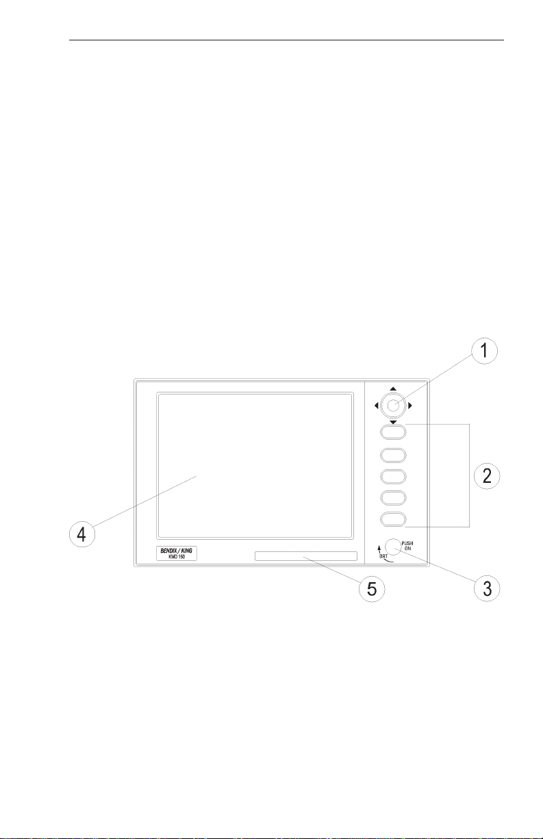
especially those most frequently used in the air. The provision of a joystick makes it considerably simpler to operate the unit and allows you
fast and efficient access to most functions.
1. Joystick
2. Function Keys
3. ON/OFF/Brightness Control
4. Full Color TFT Liquid Crystal Display
5. Database Card
Rev 1 Mar/2000 KMD 150 Pilot's Guide
9

General Information
SOFT KEYING
You will notice that a label is drawn alongside each valid key. Whenever
a new function is selected, by pressing a valid key, a new screen is displayed along with its new key labels. This capability of drawing key
labels that are only applicable to a particular screen is referred to as ‘soft
keying’, and allows one key to perform multiple functions without the
complications of multiple key presses on a conventional keypad.
For the purpose of describing the function of a particular key in this
manual, assume that all the keys on the pictured screen drawings are
numbered 1 - 5 from top to bottom. The ensuing text will use this numbering sequence to refer to each specific key. The number shown alongside the pictured screen drawings refers to the number of the screen that
is called when that key is pressed. By using these numbers it is possible
to follow the paths through the operating system for all functions. If the
word RET is printed next to a key, this means that after the key function
is performed the same screen is RETurned. A good example of this is
ZOOM IN. If the word RTS is printed next to a key, this means that after
the key function is performed the previous screen is then displayed. All
screen drawings show the KMD 150 running from it’s internal GPS
receiver. Variations affecting the KMD 150 when connected to an
external GPS are described in the accompanying text.
SELECTABLE GPS D ATA SOURCE
The KMD 150 is available with or without an internal GPS receiver. The
internal GPS version of KMD 150 has a built in eight channel parallel
GPS receiver but like the non-GPS version, can also accept data from
an external source such as a Bendix/King KLN 89B if necessary. When
set to internal GPS source, all waypoint and flight plan programming is
carried out and executed on the KMD 150. When using the internal GPS
receiver, the KMD 150 can also drive your autopilot and panel mounted
indicators and annunciators.
If you have the non-GPS version of KMD 150 or if an external GPS
source is selected for use with the full GPS version, all internal navigation options are inhibited on the KMD 150 and instead, the active flight
plan and waypoints are imported directly from the host GPS. When
using external GPS data, the KMD 150’s autopilot and annunciator outputs are disabled.
The navigation data source is always annunciated in Map Mode by a
small label located in the upper left of the screen. This label will show
INT NAV when using the internal GPS receiver and EXT NAV when
using an external GPS or LORAN receiver.
Rev 1 Mar/2000
10
KMD 150 Pilot's Guide

General Information
STORMSCOPE OPTION
The KMD 150 has the ability to interface and control a BFGoodrich WX500 Stormscope ‘black box’ thunder storm sensor. The Stormscope
interface is switched on and off by using the joystick while displaying the
Main Menu screen. When the Stormscope interface is selected on, Key
1 on the main menu screen gives access to a dedicated Stormscope
screen. If selected in the Map Setup menus, lightning icons will also
appear on the map screens along with a visual and aural warning that
there are thunderstorms in your vicinity.
SOFTW ARE ARCHITECTURE
The software in your KMD 150 unit is tree structured. An analogy can
therefore be drawn between the trunk of a tree and MAIN MENU. MAIN
MENU is the heart of the operating structure and can be accessed by
pressing the HELP key after switching on the unit or pressing the MAIN
MENU key at any other time.
MAIN MENU has 5 main software branches, which in turn have their
own sub software branches. The diagram overleaf depicts the complete
tree structure and will serve as a good point of reference while you are
familiarizing yourself with your unit.
Rev 1 Mar/2000 KMD 150 Pilot's Guide
11

General Information
GPS STATUS If using the internal GPS, this shows satellite signal
strength, allows UTC, local offset, date and position to be set, which will
speed up the initialization of your unit.
DATA I/O If using an external GPS, this shows the data
input/output settings and status.
STORMSCOPE If a WX-500 Stormscope is interfaced; this shows a
Stormscope style display of the local thunderstorm activity.
FLIGHT PLAN Allows user defined user waypoints and flight plans to
be edited/created.
EDIT FPLN Allows user defined flight plans to be edited /created
either manually or visually.
USER WPTS Allows user defined user waypoints, airports and
marker functions to be edited/created either manually or visually.
DEMO MODE Allows you to practice operating the unit on the ground
using a built in simulator. This is available only on units with an internal
GPS active.
NOTE PAD Allows up to 4000 characters of text, previously downloaded from a PC using Flight Manager(tm) software to be viewed. This
key in only available if DEMO MODE is not running. DEMO MODE can
only be selected from the first screen when switching on the unit.
E6-B CALC Allows the E6-B Calculator to be used.
TAS/WIND
NAV
TRIP/FUEL
SUNSET/RISE
SETUP Allows Setup of map, navigation and input/output char-
acteristics.
MAP SETUP Allows all map functions to be customized, including
map tracking, airport names, map units, map datum, language, minimum
runway length/surface, extended track, auto zoom and zoom level map
de-clutter facility.
NAV SETUP Allows all the NAV functions to be customized,
including CDI scale, CDI display, CDI alarm, arrival alarm, auto next
leg/leg selection philosophy, turn anticipation and logging rate.
Rev 1 Mar/2000
Allows density altitude, TAS and winds aloft to be
calculated.
Allows vertical navigation to be Setup.
Allows fuel and trip information to be calculated.
Allows sunset and sunrise times to be calculated.
12
KMD 150 Pilot's Guide

General Information
PIN SETUP Allows the PIN security function to be Setup.
INST & DIAGS Allows installation and diagnostics for data input/output
and GPS receiver (KMD 150 only) to be performed. Flight logs can be
viewed and various sections of memory can be cleared from here.
MAP This is the primary operating mode of the unit. The unit
will automatically drop into this mode 30 seconds after switch on if no
other key is activated.
NAV MENU Accesses all navigation functions and MSA information.
Joystick toggles NAV Mode.
FLIGHT PLAN
NEAR APTS
NEAR NAVAID
SAVE WPT
DIRECT TO Allows the user to perform a DIRECT TO any point in
the internal or user defined database. It may also be used to obtain
information on any point in the database.
There are short cuts that allow you to get to the primary operating mode,
MAP mode, more easily; but in general if you wish to get to a specific
function in another branch of software, work your way back up the present branch to MAIN MENU by pressing either the PREV PAGE or MAIN
MENU keys. Then select the branch of software that contains the
desired function you wish to access.
Allows a Flight Plan to be selected and edited.
Allows emergency search of 10 nearest airports,
providing information and DIRECT TO capability.
Includes Jeppesen and user defined airports
which satisfies the minimum runway length and
surface requirements.
Allows emergency search of 10 nearest navaids
(VORs and NDBs), providing information and
DIRECT TO capability.
Allows your present co-ordinates to be saved in the
next available user waypoint number.
Rev 1 Mar/2000 KMD 150 Pilot's Guide
13

General Information
SCREEN ICONS
When showing any map screen - airports, navaids, towns, intersections,
user waypoints and many other data classes are represented by symbols or icons, some of which are user selectable in the Map Setup
Screens. Please refer to the Setup Screens Section of this manual for
further details.
OBSTACLE LABELS
Obstacles (available in the AMR cartridge for the United States only) are
labeled with two numbers. The first number is the height of the obstacle
in FEET ABOVE MSL. The second number (in brackets) is the height of
the obstacle in FEET AGL.
TERRAIN AND URBAN AREAS DISPLAY
On all map screens, the land is shaded to show rising ground in seven
elevation levels similar to those seen on a paper chart. In addition, all
built up or urban areas are shaded light gray. The levels and colors for
the terrain shading are:
TERRAIN
Color ATI Level AMR & PAI Level
Light Green Less Than 500 feet Less Than 1000 feet
Medium Green 501-1000 feet 1001-2000 feet
Dark Green 1001-2000feet 2001-3000 feet
Light Brown 2001-3000 feet 3001-5000 feet
Medium Brown 3001-5000 feet 5001-9000 feet
Dark Brown 5001-9000 feet 9001-13000 feet
White Greater Than 9001 feet Greater Than 13001 feet
Rev 1 Mar/2000
14
KMD 150 Pilot's Guide

General Information
NOTE:
Terrain data is not available for certain areas of SOUTH AMERICA centering on the Amazon Basin and in EUROPE a larger portion of the
Ukraine bordering Russia. Please exercise extreme caution when flying
in these areas because all terrain is displayed as less than 1000 feet/500
feet respectively, on the KMD 150.
A color key is displayed on the Nav Menu (or Map Menu if in External
GPS Mode). This is just one key press away from the main Map screen
so you can refer to it easily during flight.
By default, terrain data is displayed at all zoom levels. The display of terrain data can however be switched on and off at different zoom levels if
desired. See the section covering the Map Setup screen for more
details.
WARNING
NEVER USE THE TERRAIN DISPLAYED ON THIS EQUIPMENT AS
YOUR SOLE REFERENCE FOR TERRAIN AVOIDANCE.
MEMORY LOCATIONS
In the function descriptions, three types of memory, EPROM, RAM and
NVM, are mentioned. You may find it useful to know where various
types of information are stored in order to make best use of the equipment. The EPROM’s (Erasable Programmable Read Only Memory) are
in the database card and are used to hold the operating system and the
database. The database card can be replaced periodically in order to
upgrade the operating system and update the database. The RAM
(Random Access Memory) is built into the unit and is used to store all
user-defined data such as User waypoints and Flight Plans. The RAM is
maintained by battery power from an internal Lithium cell that should be
replaced by your Bendix/King dealer every three years to prevent loss of
user-defined data. The NVM (Non Volatile Memory) is also built into the
unit. It stores initialization data, serial number, PIN number and performance log details. This memory is non-volatile, which means it is
retained even if the memory battery is removed. If you choose to activate
the PIN number security feature (similar to that available on many car
radios) the non-volatile nature of the NVM ensures your PIN can not be
tampered with or erased.
Rev 1 Mar/2000 KMD 150 Pilot's Guide
15

General Information
Intentionally left blank
Rev 1 Mar/2000
16
KMD 150 Pilot's Guide
 Loading...