

Page 1
N
Pilot’s Guide
KLN 94
Bendix/King
GPS Navigation System
ORS 01, 02 and 03
®
Page 2

WARNING
Prior to export of this document, review for export license requirement is needed.
COPYRIGHT NOTICE
Copyright ©2000-2002 Honeywell International Inc. All rights reserved.
Reproduction of this publication or any portion thereof by any means without the
express written permission of Honeywell International Inc. is prohibited. For further information contact the Manager, Technical Publications; Honeywell; One
Technology Center; 23500 West 105th Street; Olathe, Kansas 66061.
Telephone: (913) 782-0400.
Page 3

KLN 94 Pilot’s Guide
006-18207-0000
Operational Revision Status
ORS 01, 02 and 03
July 2002
The ORS level is annunciated on the Turn-on page each time power is
applied to the KLN 94 (see figure 3-3). Features limited to specific ORS
levels are so designated in the text of this manual. The operational differences between ORS levels are described below.
ORS 02: Operational characteristics are similar to ORS 01 with the exception of the following primary differences:
(1) Enhanced waypoint scanning on the Nav 4 map page encircles the way-
point whose identifier is contained in the waypoint scan field. In addition,
pressing the ENT button brings up the waypoint page for the selected
waypoint. See section 3.11.4.11.
(2) Procedure turns and holding patterns associated with approaches, DPs,
and STARs are displayed on the map. See section 3.11.4.12.
(3) New airport map icons now distinguish between airports having hard sur-
face runways vs. soft surface runways and show the orientation of the
longest runway if available. See section 3.11.4.7.
(4) New highway map icons are used for the Atlantic International and
Pacific International databases. See section 3.11.4.7.
(5) There is a new message that appears if the database card is removed
while the KLN 94 is operational. See Appendix B.
(6) The default value for intersections has been changed from 2NM to OFF
on the SET 7 page.
(7) A software problem was fixed which now allows updating of the
Aeronautical database with a computer via diskettes or the Internet. See
sections 2.4.1 and 2.4.2.
(8) The Database page has been modified to display the region for the Land
database. See section 3.2.
(9) Approaches which have the format of “RNAV # 18L” can now be acco-
modated. The “#” is a letter
one approach of a given type (i.e. RNAV) to the same runway. This format has been adopted by the FAA and other international aviation
agencies.
Example 1: There could be RNAV Y 18L and RNAV Z 18L
approaches at the same airport.
Example 2: There could be RNAV 1 09L and RNAV 2 09L
approaches at the same airport
ORS 03: Operational characteristics are similar to ORS 02 with the exception that Special Use Airspace inner rings may be displayed on the Nav 4
map page. See section 3.11.4.4.
or number that designates there is more than
Page 4

NOTE: A white border is used around
data on some of the figures in this Pilot's
Guide to indicate that the data inside the
border is flashing.
WARNING: The KLN 94 displays GPS-derived altitude on the AUX 1
page. Due to many factors, GPS altitude may typically be several
hundred feet in error. Do not use the GPS-derived altitude for navigation.
IMPORTANT: Special installation procedures must be followed in order
for the KLN 94 to be certified for IFR En route, Terminal and Non-precision
Approach use. If these procedures are followed, the KLN 94 can be used
for IFR use. Consult the aircraft’s KLN 94 Flight Manual Supplement for
the operating limitations of this unit.
IMPORTANT: The KLN 94 has two software configuration numbers, one
for the boot software and one for the application software. It may be useful
for you to obtain these software configuration numbers to aid maintenance
personnel if service is required on your KLN 94. The boot software configuration number is displayed on a label located on the KLN 94’s top cover.
The bottom of the label reads “BOOT SOFTWARE MOD” followed by the
four digit configuration number. The application software configuration
number is available on the top line of the Auxiliary (AUX) 14 page. It reads
“SW REVISION” followed by a four digit configuration number. These software configuration numbers should have been recorded in the aircraft’s
logbook at the time of KLN 94 installation or time of a later software
update.
Page 5

Revision History and Instructions
Manual KLN 94 Pilot’s Guide
Revision 2, July 2002
Part Number 006-18207-0000
This revision incorprates software changes for ORS 03.
R-1
Page 6

Revision History and Instructions
Manual KLN 94 Pilot’s Guide
Revision 1, March 2001
Part Number 006-18207-0000
This revision incorprates software changes for ORS 02.
R-2
Page 7

Revision History and Instructions
Manual KLN 94 Pilot’s Guide
Revision 0, September 2000
Part Number 006-18207-0000
This is the original version of this publication.
R-3
Page 8

This page intentionally left blank.
R-4
Page 9

KLN 94 Pilot’s Guide Table of Contents
INTRODUCTION ............................................................................i
KLN 94 SNEAK PREVIEW ...............................................................ii
HOW-TO INDEX ..........................................................................iv
1. KLN 94 System Components ..................................................1-1
2. Database ........................................................................2-1
2.1. Functions of the Database ................................................2-1
2.2. Database Contents and Coverage Areas .........................2-1
2.3. ICAO Identifiers .................................................................2-4
2.4. Updating the Database .....................................................2-4
2.4.1. Computer Updating of the Database (diskettes) ...2-6
2.4.2. Computer Updating of the Database (internet) ......2-8
2.4.3. Card Exchange Updating of the Database ............2-8
2.5. User Defined Database .....................................................2-9
2.6. Database Update Service Options ...................................2-9
3. Basic GPS Operation ................................................................3-1
3.1. Coverage Area ..................................................................3-1
3.2. Turn-on and Self Test .......................................................3-1
3.3. Display Format ..................................................................3-9
3.4. Basic Operation of Panel Controls ..................................3-12
3.4.1. Page Selection ......................................................3-12
3.4.2. Data Entry ..............................................................3-14
3.4.3. The Duplicate Waypoint Page ..............................3-16
3.5. Message Page ................................................................3-18
3.6 Scratchpad Messages .....................................................3-18
3.7. Initialization and Time to First Fix ...................................3-19
3.8. Selecting and Scanning Waypoints ................................3-21
3.8.1. Selecting Waypoints by Identifier ..........................3-21
TOC-1
Page 10

Table of Contents
3.8.2. Selecting Waypoints by Scanning .........................3-23
3.8.3. Selecting Waypoints by Name or City ..................3-24
3.9. “Nearest” Functions ........................................................3-27
3.9.1. Viewing the Nearest Waypoints ............................3-28
3.9.1.1 Nearest Airport Criteria ................................3-28
3.9.1.2 Continuous Display of Nearest Airport ........3-29
3.9.2. Viewing the Nearest Special Use Airspaces ........3-30
3.9.3. Viewing the Nearest Flight Service Station
Frequencies .....................................................................3-31
3.9.4. Viewing the Nearest Center Frequencies .............3-32
3.10. Direct To Operation .......................................................3-33
3.10.1. Initiating a Direct To ............................................3-34
3.10.2. Cancelling a Direct To .........................................3-36
3.10.3. Waypoint Alerting for Direct To Operation ..........3-36
3.11. Navigation Pages ..........................................................3-37
3.11.1. The Navigation 1 (NAV 1) Page ..........................3-37
3.11.2. The Navigation 2 (NAV 2) Page ..........................3-39
3.11.3. The Navigation 3 (NAV 3) Page ..........................3-40
3.11.4. The Navigation 4 (NAV 4) Page – Moving Map .3-40
3.11.4.1 Selecting The NAV 4 (Map) Page ............3-40
3.11.4.2 NAV 4 Page Format .................................3-41
3.11.4.3. Selecting What Is Shown On The Map ...3-42
3.11.4.4. Configuring Aeronautical Data For
The Map ....................................................................3-42
3.11.4.5. Runway Diagrams ..................................3-44
3.11.4.6. Configuring Land Data On The Map .......3-44
3.11.4.7. Symbols Used On The Map ....................3-46
3.11.4.8. Selecting The Map Orientation ................3-46
TOC-2
Page 11

KLN 94 Pilot’s Guide Table of Contents
3.11.4.9. Changing the Map Range Scale .............3-47
3.11.4.10 Decluttering The Screen .........................3-48
3.11.4.11. Waypoint Scan Feature .........................3-48
3.11.4.12. Holding Patterns and Procedure Turns .3-50
3.12. Waypoint Pages ............................................................3-51
3.12.1. Airport Pages .......................................................3-51
3.12.1.1. The Airport 1 (APT 1) Page .......................3-51
3.12.1.2. The Airport 2 (APT 2) Page .......................3-52
3.12.1.3. The Airport 3 (APT 3) Page .......................3-53
3.12.1.4. The Airport 4 (APT 4) Page ......................3-54
3.12.1.5. The Airport 5 (APT 5) Page ......................3-55
3.12.1.6. The Airport 6 (APT 6) Page .......................3-57
3.12.1.7. The Airport 7 (APT 7) Page ......................3-58
3.12.1.8. The Airport 8 (APT 8) Page .......................3-59
3.12.2. VOR Pages .........................................................3-60
3.12.2.1. The VOR 1 Page ......................................3-60
3.12.2.2. The VOR 2 Page ......................................3-61
3.12.3. NDB Page ...........................................................3-61
3.12.3.1. The NDB 1 Page ......................................3-61
3.12.4. Intersection Pages ...............................................3-62
3.12.4.1. The Intersection 1 (INT 1) Page ...............3-62
3.12.4.2. The Intersection 2 (INT 2) Page ...............3-63
3.12.5. User Waypoint Pages ........................................3-63
3.12.5.1. The User 0 (USR 0) Page .........................3-63
3.12.5.2. The User 1 (USR 1) Page ........................3-64
3.12.5.3. The User 2 (USR 2) Page ........................3-64
3.12.5.4. The User 3 (USR 3) Page .........................3-64
TOC-3
Page 12

Table of Contents
3.13. Special Use Airspace Alerting ......................................3-66
3.14. Remote Mounted Annunciators ....................................3-69
3.15 QuickTune™ Nav/Comm Frequency Selection .........3-70
3.15.1. Quicktune™ Operation with One
Compatible NAV/COMM .................................................3-71
3.15.2. Quicktune™ Operation with More Than One
Compatible NAV/COMM .................................................3-72
3.16. Using the Take-home Mode .........................................3-72
3.17 Sample Trip ...................................................................3-74
3.17.1 Pre-departure ......................................................3-74
3.17.2 En route ...............................................................3-75
3.17.3 Terminal Area ......................................................3-76
4. Flight Plan Operation ...............................................................4-1
4.1. Creating and Modifying Flight Plans .................................4-1
4.1.1. Creating a Flight Plan .............................................4-1
4.1.2. Viewing Distance and Desired Track Between
Stored Flight Plan Waypoints ............................................4-4
4.1.3. Activating a Numbered Flight Plan .........................4-4
4.1.4. Adding a Waypoint to a Flight Plan ........................4-5
4.1.5. Deleting a Waypoint from a Flight Plan ..................4-6
4.1.6. Deleting Flight Plans ..............................................4-7
4.1.7. Storing FPL 0 as a Numbered Flight Plan ..............4-7
4.2. Operating from the Active Flight Plan ...............................4-8
4.2.1. General Procedures ................................................4-8
4.2.2. Turn Anticipation and Waypoint Alerting ...............4-10
4.2.3. Viewing the Waypoint Pages for the Active
Flight Plan Waypoints ......................................................4-11
4.2.4. Combining Direct To and Flight Plan Operation ...4-12
4.2.4.1 Direct To Operation From The Map .............4-12
TOC-4
Page 13

KLN 94 Pilot’s Guide Table of Contents
4.2.4.2 Direct To Operation From Any Page ...........4-12
4.2.4.3 Direct To Operation From The FPL 0 Page 4-13
4.2.4.4 Cancelling Direct To Operation ....................4-13
4.2.5. Viewing Distance, ETE, ETA, or Desired Track to
Flight Plan Waypoints ......................................................4-14
4.2.6 Changing The System Time Zone ........................4-15
5. Intermediate Operation ............................................................5-1
5.1. Altitude pages ...................................................................5-1
5.2. Advisory VNAV Operation .................................................5-3
5.2.1. VNAV for Direct To Operation .................................5-3
5.2.2. VNAV for Flight Plan Operation ..............................5-6
5.3. Altitude Alerting .................................................................5-6
5.4. Creating User-defined Waypoints ....................................5-9
5.4.1. Creating a Waypoint at Your Present Position .....5-10
5.4.2. Creating a Waypoint at a Certain Latitude/
Longitude ......................................................................5-11
5.4.3. Creating a Waypoint Referenced from Another
Waypoint ......................................................................5-12
5.5. Navigation Modes ...........................................................5-14
5.5.1. Selecting the Leg Mode or the OBS mode ...........5-14
5.5.2. The Leg Mode .......................................................5-14
5.5.3. The OBS Mode ......................................................5-15
5.5.4. Switching From the Leg Mode to the OBS mode .5-17
5.5.5. Effects of Switching From OBS Mode to
Leg Mode ......................................................................5-17
5.5.6. Going Direct To a Waypoint While in the
OBS Mode .....................................................................5-18
5.5.7. Activating a Waypoint While in the OBS Mode .....5-18
5.6. Changing the CDI Scale Factor ......................................5-19
5.7. Avionics Bus Voltage Alerting ........................................5-20
TOC-5
Page 14

Table of Contents
5.8. The Auxilary (AUX) Pages ..............................................5-21
5.9. Determining the Status of the GPS Signals ....................5-21
5.10. Calculator (AUX 4 – AUX 11) pages ............................5-24
5.10.1. The Auxilary 4 (AUX 4) Trip Planning Page .......5-24
5.10.2. The Auxilary 5 (AUX5) Trip Planning Page ........5-26
5.10.3. The Auxilary 6 (AUX 6) Pressure Altitude Page .5-27
5.10.4. The Auxilary 7 (AUX 7) Density Altitude Page ...5-28
5.10.5. The Auxilary 8 (AUX 8) True Airspeed Page ......5-29
5.10.6. The Auxilary 9 (AUX 9) Wind Page ....................5-30
5.10.7. The Auxilary 10 (AUX 10) Alarm Page ...............5-30
5.10.8. The Auxilary 11 (AUX 11) Sunrise/Sunset Page 5-31
5.11. Viewing and Deleting User Waypoints and Waypoint
Remarks (AUX 12 and AUX 13 pages) .................................5-32
5.11.1. The AUX 12 Page ...............................................5-32
5.11.2. The AUX 13 Page ...............................................5-33
5.12. Viewing the KLN 94 Software Status (AUX14 page) .5-34
5.13. The Fuel Management (AUX 15 – AUX 19) Pages .....5-34
5.13.1. The Auxilary 15 (AUX 15)Fuel Management
Page ......................................................................5-35
5.13.2 The Auxilary 16 (AUX 16) Fuel Management
Page ......................................................................5-36
5.13.3. The Auxilary 17 (AUX 17)Fuel Management
Page ......................................................................5-36
5.13.4. The Auxilary (AUX 18)Fuel Management Page .5-37
5.13.5. The Auxilary (AUX 19) Fuel Management Page 5-37
5.14. The Air Data (AUX 20 – AUX 21) Pages ......................5-37
5.14.1. The Auxilary 20 (AUX 20) Air Data Page ...........5-38
5.14.2. The Auxilary 21 (AUX 21) Air Data Page ............5-38
5.15 Viewing and Setting the Date and TimePage ................5-39
TOC-6
Page 15

KLN 94 Pilot’s Guide Table of Contents
5.16. Manual Magnetic Variation Selection ...........................5-41
5.17. Setting the Units of Measure ........................................5-42
6. APPROACHES and DP/STARs ..............................................6-1
6.1. Procedure (PROC) Pages ...............................................6-1
6.2. Non-Precision Approach Operations ................................6-2
6.2.1. Approach Mode Annunciations ..............................6-3
6.2.2. General Procedure for Non-Precision Approaches 6-4
6.2.3. Selecting and Loading An Approach .....................6-6
6.2.4. Interpreting What You See .....................................6-9
6.2.5. Changing Or Deleting An Approach Once
Loaded Into The Flight Plan ............................................6-11
6.2.6. GPS Approach Examples ....................................6-13
6.2.7. Approach Example 1: No Procedure Turn .........6-13
6.2.8. Approach Example 2: Radar Vectors ................6-20
6.2.9. Approach Example 3: Course Reversal with
Off-Airport IAF ...............................................................6-24
6.2.10. Approach Example 4: Course Reversal with
On-Airport IAF .................................................................6-26
6.2.11. Approach Example 5: DME Arc ......................6-30
6.2.12. ILS and other Non-Approved Approaches .........6-35
6.2.13. Using GPS Distance as a Substitute for DME
on Localizer-type Approaches .........................................6-36
6.2.14. Approach Problems ...........................................6-37
6.3. DP/STAR PROCEDURES .............................................6-39
6.3.1. Selecting a DP ......................................................6-40
6.3.2. Selecting a STAR ................................................6-42
6.3.3. Editing a DP or STAR ..........................................6-43
6.3.4. Example of a DP Procedure ................................6-45
6.3.5. Example of a STAR Procedure ............................6-47
TOC-7
Page 16

Table of Contents
APPENDIX A - NAVIGATION TERMS .........................................A-1
APPENDIX B - MESSAGE PAGE MESSAGES ..........................B-1
APPENDIX C - SCRATCHPAD MESSAGES ..............................C-1
APPENDIX D - ABBREVIATIONS ................................................D-1
STATE ABBREVIATIONS .......................................................D-1
CANADIAN PROVINCE ABBREVIATIONS ...........................D-2
COUNTRY ABBREVIATIONS ................................................D-2
ARTCC ABBREVIATIONS ......................................................D-8
OTHER ABBREVIATIONS USED ON KLN 94 PAGES .......D-17
APPENDIX E - LAT/LON CONVERSIONS ..................................E-1
APPENDIX F - GPS PRIMER ........................................................F-1
BACKGROUND .......................................................................F-1
GPS POSITION DETERMINING CONCEPT .........................F-1
GPS DATA SIGNALS ..............................................................F-1
GPS SYSTEM SEGMENTS ....................................................F-2
RAIM ........................................................................F-3
GPS XPRESS™ CARD 8-CHANNEL RECEIVER .................F-3
APPENDIX G- OPERATIONAL COMPARISON WITH KLN 89B G-1
TOC-8
Page 17

KLN 94 Pilot’s Guide Introduction
INTRODUCTION
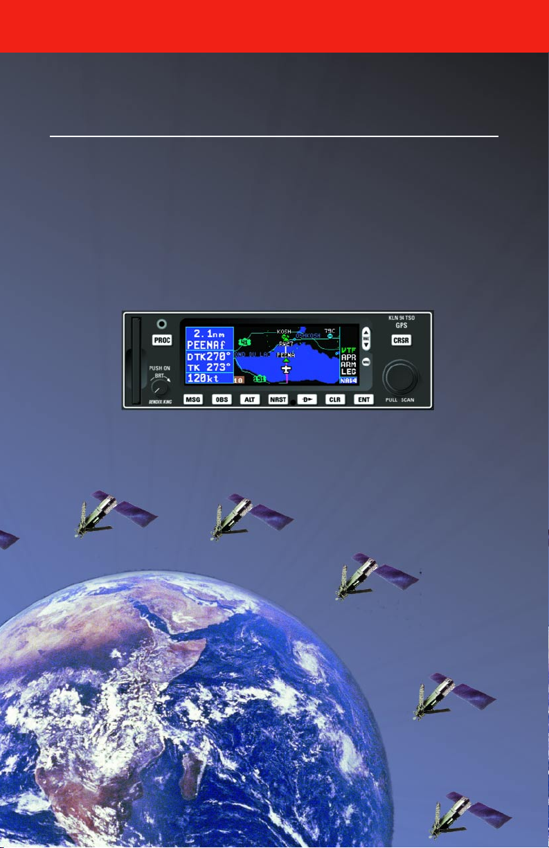
Congratulations for choosing the Bendix/King KLN 94 GPS! Celestial
navigation will now be a way of life for you. The phenomenal accuracy of
GPS, along with the KLN 94’s user-friendly operation and color graphics
display will make flying a delight. Not only will the KLN 94 help you to
navigate more easily and more accurately, its trip planning features, air
data calculations, and other useful features will make you feel like you’re
flying with a true flight management system.
In addition, KLN 94 may be IFR approved for En route, Terminal, and
Non-precision Approach operations. We think you’ll find that having an
abundance of navigational data (not to mention a moving map!) available
to you will make non-precision approaches more precise and more enjoyable.
This Pilot’s Guide will be of great help to you. It is written in plain, simple
English and it assumes you are not an experienced user of GPS or other
type of long range navigation equipment. If you are experienced, so much
the better. This Pilot’s Guide also includes hundreds of sample screen figures and other illustrations to make your learning easier. It is designed so
that you can start at the front and progress in the order presented; however, you may want to skip around and learn things in your own order. Also,
on page iv, there is an index of frequently used procedures which will help
you find the page that describes how to do exactly what you want to do.
There are also several appendices in the back of the manual that you may
find useful from time to time.
If you are an experienced KLN 89B user, Appendix G outlines the
KLN 94’s new features and operational enhancements.
Be sure to keep this Pilot’s Guide handy with you in the airplane. It is
designed to fit easily in the glove box, or in the seat pocket.
One last thing. Don’t get so involved in learning to use the KLN 94 that
you forget to fly the airplane. Be careful, and remember to keep a close
eye out for other aircraft.
i
Page 18

Introduction
KLN 94 SNEAK PREVIEW
If you absolutely can’t wait to use your KLN 94 until you’ve read this Pilot’s
Guide, this section is for you. This short section will teach you just enough
to get going and then learn by doing. This operational preview assumes
the KLN 94 has been properly installed, the unit was previously operational in the same general geographical location, and that no peripheral
equipment interfaced with the KLN 94 (such as external HSI’s, CDI’s,
autopilots, moving map display, etc.) is to be used at this time. If you are
using this operational preview in flight, do so only in good VFR conditions
and only with an alternate means of navigation available to cross-check
position.
1. Turn the unit on by pressing the On/Off/Brightness knob (the small
knob in lower left hand corner). After the screen changes to full color,
rotate the knob to adjust the display brightness to the desired level.
2. For about 50 seconds the Power On Page is displayed while the unit
runs a self-test. (If the unit is in the Take-Home mode a Take-Home
page is displayed. Press the F button to acknowledge the TakeHome mode). Afterwards, the Self-test Page is displayed. If the
KLN 94 is receiving an altitude from an encoding altimeter, the present
indicated altitude will be displayed on line 2. The bottom line should
display Pass with the cursor over a flashing Ok?. Press the F button to approve the Self-test Page.
3. The Initialization Page will now be displayed. If the date and time are
incorrect by more than 10 minutes, refer to section 3.2 of this Pilot’s
Guide. The right side of the screen should show the identifier of the
nearest airport to the initial position, along with a radial and distance
from that airport waypoint. Press F with the cursor flashing over
Ok? to approve the Initialization Page.
4. If your KLN 94 has been configured for VFR use only, the VFR page
will now be displayed to notify you of the VFR limitation. Press F to
approve this page.
5. The Database Page is now displayed showing the date the database
expires or the date it expired. Press F to acknowledge the information displayed on this page.
ii
Page 19

KLN 94 Pilot’s Guide Introduction
6. Use the right outer knob to turn to the NAV page type. Watch the
page bar at the very bottom of the screen. As the outer knob is turned
the selected page type becomes reverse video (white letters on a blue
background). Turn until NAV is selected. Then use the right inner
knob to select the NAV 2 page if not already there. The NAV 2 page
shows your present position relative to a nearby VOR. It may take a
couple minutes for the GPS receiver to “wake-up” and determine a
position. Verify that this position is correct before proceeding.
7. Press the D button. A page with the words DIRECT TO: is now displayed on the screen.
In step 8 you will enter the ICAO identifier of the airport. The identifier will
have a “K” prefix for a Continental U.S. airport, a “C” prefix for a Canadian
airport, or a “P” prefix (in some cases) for an Alaskan airport if the identifier
is all letters. For example, LAX becomes KLAX. For these countries if the
identifier contains any numbers, there is no prefix. For example, TX04 is
entered TX04. For other areas of the world the airport identifier should be
entered identically to how it is charted.
8. Rotate the right inner knob until the first character of the airport identifier is displayed. Turn the right outer knob one step clockwise to move
the flashing segment to the second character position. Rotate the right
inner knob to select the second character of the identifier. Use this
procedure to enter the complete airport identifier.
9. Press F. The display will change to a page showing the identifier,
name, city, and state/country of the airport just entered. Confirm that
the correct airport is displayed. Press F a second time to approve
the airport data.
10. A Navigation page (specifically the NAV 1 page) is now on the screen.
The left side of the display (blue background) shows distance, groundspeed, desired track (DTK is the course to be flown), and actual track
(TK is the actual course the aircraft is currently tracking over the
ground). The large middle section of the display shows the active
waypoint, a course deviation indicator (CDI), bearing to the waypoint,
and estimated time en route (ETE). Beneath the CDI are located a
digital display of the deviation and the CDI scale.
iii
Page 20

Introduction
HOW-TO INDEX
This index will help you quickly find important procedures at a glance. The
list is alphabetized by action words.
TO: SEE Section:
Activate one of the previously created numbered flight plans . . . . . . . . . . . . .4.1.3
Add a waypoint to a flight plan . . . . . . . . . . . . . . . . . . . . . . . . . . . . . . . . . . . . .4.1.4
Add an individual waypoint in the DP or STAR procedure . . . . . . . . . . . . . . . .6.3.3
Calculate distance, time, and ESA for a flight plan . . . . . . . . . . . . . . . . . . . .5.10.1
Calculate distance, bearing, and time from waypoint to waypoint . . . . . . . . .5.10.1
Calculate fuel requirements for a flight plan . . . . . . . . . . . . . . . . . . . . . . . . . .5.10.2
Calculate fuel requirements from waypoint to waypoint . . . . . . . . . . . . . . . . .5.10.2
Calculate sunrise/sunset times . . . . . . . . . . . . . . . . . . . . . . . . . . . . . . . . . . . .5.10.8
Calculate the density altitude . . . . . . . . . . . . . . . . . . . . . . . . . . . . . . . . . . . . .5.10.4
Calculate the pressure altitude . . . . . . . . . . . . . . . . . . . . . . . . . . . . . . . . . . . .5.10.3
Calculate the true airspeed (TAS) . . . . . . . . . . . . . . . . . . . . . . . . . . . . . . . . . .5.10.5
Calculate the winds aloft . . . . . . . . . . . . . . . . . . . . . . . . . . . . . . . . . . . . . . . . .5.10.6
Cancel Direct To operation . . . . . . . . . . . . . . . . . . . . . . . . . . . . . . . . . . . . . . .3.10.2
Change between distance and desired track display on a numbered flight
plan page . . . . . . . . . . . . . . . . . . . . . . . . . . . . . . . . . . . . . . . . . . . . . . . . . . . . . .4.1.2
Change between distance, ETE, ETA, and desired track on the FPL 0 page .4.2.5
Change course modes . . . . . . . . . . . . . . . . . . . . . . . . . . . . . . . . . . . . . . . . . . . . .5.5
Change or delete an entire DP or STAR procedure from the active
flight plan . . . . . . . . . . . . . . . . . . . . . . . . . . . . . . . . . . . . . . . . . . . . . . . . . . . . . .6.3.3
Change the baro setting . . . . . . . . . . . . . . . . . . . . . . . . . . . . . . . . . . . . . . . . . . . .5.1
Change the CDI scale factor . . . . . . . . . . . . . . . . . . . . . . . . . . . . . . . . . . . . . . . .5.6
Change the default first waypoint character . . . . . . . . . . . . . . . . . . . . . . . . . . .3.4.2
Change the NAV 2 page present position reference waypoint . . . . . . . . . . .3.11.2
Change the present fuel on board . . . . . . . . . . . . . . . . . . . . . . . . . . . . . . . . .5.13.1
Change the selected course in OBS mode . . . . . . . . . . . . . . . . . . . . . . . . . . .5.5.3
Create a flight plan . . . . . . . . . . . . . . . . . . . . . . . . . . . . . . . . . . . . . . . . . . . . . . . .4.1
Create a user-defined waypoint at your present position . . . . . . . . . . . . . . . . .5.4.1
Create a user-defined waypoint using the radial/distance method . . . . . . . . .5.4.3
Create a user-defined waypoint with latitude/longitude . . . . . . . . . . . . . . . . . .5.4.2
Delete a flight plan which is no longer required . . . . . . . . . . . . . . . . . . . . . . . .4.1.6
Delete a user-defined waypoint from the AUX 12 page . . . . . . . . . . . . . . . . .5.11.1
Delete a waypoint from a flight plan . . . . . . . . . . . . . . . . . . . . . . . . . . . . . . . . .4.1.5
iv
Page 21

KLN 94 Pilot’s Guide Introduction
TO: SEE Section:
Delete a waypoint remark from the AUX 13 page . . . . . . . . . . . . . . . . . . . . .5.11.2
Delete an approach from FPL 0 . . . . . . . . . . . . . . . . . . . . . . . . . . . . . . . . . . . .6.2.5
Delete an individual waypoint in a DP or STAR procedure . . . . . . . . . . . . . . .6.3.3
Display the nearest airport continuously . . . . . . . . . . . . . . . . . . . . . . . . . . . .3.9.1.2
Enable the voltage alert feature . . . . . . . . . . . . . . . . . . . . . . . . . . . . . . . . . . . . . .5.7
Enter a user-defined waypoint remark on the USR 3 page . . . . . . . . . . . . .3.12.5.4
Enter a waypoint identifier . . . . . . . . . . . . . . . . . . . . . . . . . . . . . . . . . . . . . . . . .3.4.2
Enter an airport remark on the APT 6 page . . . . . . . . . . . . . . . . . . . . . . . . .3.12.1.6
Enter the local magnetic variation manually on the SET 2 page . . . . . . . . . . . .5.16
Fly direct to a waypoint . . . . . . . . . . . . . . . . . . . . . . . . . . . . . . . . . . . . . . . . . . . .3.10
Fly direct to a waypoint in the active flight plan (FPL 0) . . . . . . . . . . . . . . . . . .4.2.4
Initialize the position from the SET 1 page . . . . . . . . . . . . . . . . . . . . . . . . . . . . .3.7
Perform a manual RAIM calculation . . . . . . . . . . . . . . . . . . . . . . . . . . . . . . . .6.2.14
Recenter the D-Bar by going direct to the active waypoint . . . . . . . . . . . . . .3.10.1
Replace an existing approach, or delete an approach . . . . . . . . . . . . . . . . . . .6.2.5
Select a DP . . . . . . . . . . . . . . . . . . . . . . . . . . . . . . . . . . . . . . . . . . . . . . . . . . . .6.3.1
Select a STAR . . . . . . . . . . . . . . . . . . . . . . . . . . . . . . . . . . . . . . . . . . . . . . . . . .6.3.2
Select a VOR or NDB by navaid name . . . . . . . . . . . . . . . . . . . . . . . . . . . . . . .3.8.3
Select a waypoint by identifier from a waypoint page . . . . . . . . . . . . . . . . . . . .3.8.1
Select a waypoint by scanning . . . . . . . . . . . . . . . . . . . . . . . . . . . . . . . . . . . . .3.8.2
Select an airport by scanning the airport name . . . . . . . . . . . . . . . . . . . . . . . .3.8.3
Select an approach . . . . . . . . . . . . . . . . . . . . . . . . . . . . . . . . . . . . . . . . . . . . . .6.2.3
Set the alarm . . . . . . . . . . . . . . . . . . . . . . . . . . . . . . . . . . . . . . . . . . . . . . . . . .5.10.7
Set the date on the SET 2 page . . . . . . . . . . . . . . . . . . . . . . . . . . . . . . . . . . . . .5.15
Set the time on the SET 2 page . . . . . . . . . . . . . . . . . . . . . . . . . . . . . . . . . . . . .5.15
Specify the nearest airport criteria . . . . . . . . . . . . . . . . . . . . . . . . . . . . . . . . .3.9.1.1
Store the active flight plan as a numbered flight plan . . . . . . . . . . . . . . . . . . . .4.1.7
Turn on and initialize the KLN 94 . . . . . . . . . . . . . . . . . . . . . . . . . . . . . . . . . . . . .3.2
Update the KLN 94 database by computer . . . . . . . . . . . . . . . . . . . . . . . . . . .2.4.1
Use altitude alerting . . . . . . . . . . . . . . . . . . . . . . . . . . . . . . . . . . . . . . . . . . . . . . .5.3
Use VNAV on a Direct To . . . . . . . . . . . . . . . . . . . . . . . . . . . . . . . . . . . . . . . . . .5.2
View a message . . . . . . . . . . . . . . . . . . . . . . . . . . . . . . . . . . . . . . . . . . . . . . . . . .3.5
View the waypoints in the flight plan that are not the active waypoint. . . . . . .4.2.3
View VNAV status . . . . . . . . . . . . . . . . . . . . . . . . . . . . . . . . . . . . . . . . . . . . . . . .5.2
v
Page 22
Chapter 1 System Components
HEADING
MANAGEMENT
SYSTEM
FUEL
COMPATIBLE
COMPATIBLE
COMPUTER
DATA
AIR
ALTITUDE
AIRCRAFT
POWER
REQUIRED FOR ALL INSTALLATIONS
INSTALLATION DEPENDENT
REQUIRED FOR IFR APPROACH INSTALLATIONS
KLN 94 SYSTEM
INPUT
TEST
PULL
COMM NAV
G
KX 155A or KX 165A
CHAN
STBY
PULL 25K
IDENT
PULL
TIMER
MODE
STBY
PULL OBS
KX 155A TSO
OUTPUT
RS-232
NAV
GPS
KMD 550 & 850 MFDs
AND OTHER MOVING
MAP DISPLAYS
GPS/NAV SWITCH/
ANNUNCIATOR
RS-232
RS-232
INPUT
QuickTune™
WPT ALERT
MESSAGE
ANNUNCIATORS
REMOTE
ı
D
ENTCLRMSG NRSTALTOBS
PULL SCAN
KI 229 KNI 582
ı
NAV NAV
B
RS-232
INPUT
PUSH ON
BRT
MNU
1
2
S
5
1
12
E
D
F
2
4
2
1
S
5
1
2
1
D
F
11-33V
GRAY CODE
KA 92 GPS ANTENNA
PROC
RNG
KLN 94 TSO
CRSR
GPS
LEFT/RIGHT
D-BAR
SELECTED
COURSE
DN
UP
2
4
W
A
30
D
F
33
N
3
6
RMI
OR
A
W
3
0
3
3
N
3
6
E
A
ı
RN RC PC
ALT HDG NAV APR BC
TEST
ENG
AP
AUTOPILOT
YD
KC 193
ALT HDG NAV APR APGS
BC
KI 525A KI 206
ı
GS GS
W
30
24
NAV HDG
33
21
S
15
12
HSI
N
3
6
E
OR
OBS
W
3
2
GS
3
2
B
S
F
1
1
CDI
N
NAV
TO
3
6
E
OR
1-0
KI 825
EHSI
Page 23

KLN 94 Pilot’s Guide Chapter 1 System Components
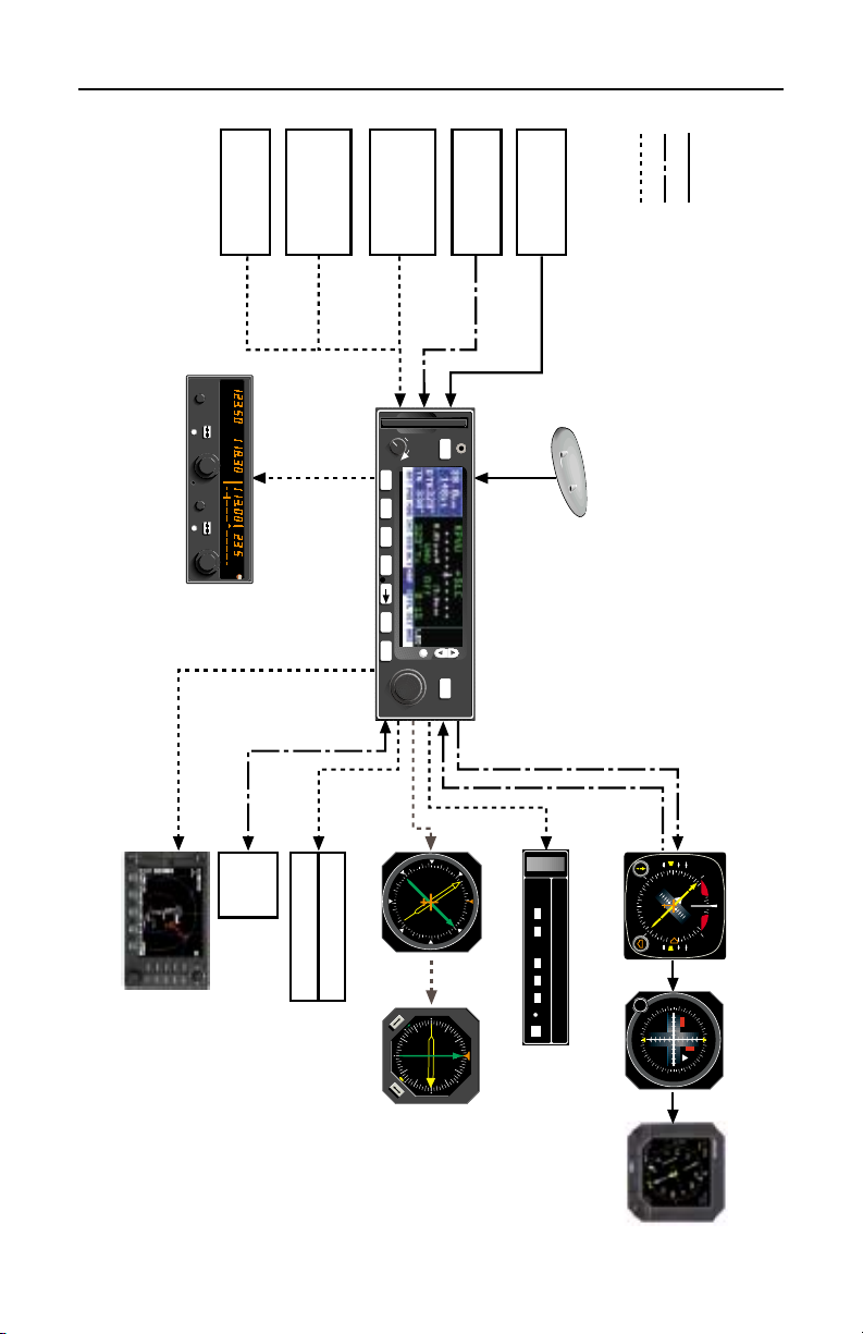
1. KLN 94 SYSTEM COMPONENTS
A basic KLN 94 system consists of a panel mounted KLN 94 GPS and a
KA 92 GPS antenna. An altitude input is required to obtain full navigation
and operational capabilities. Additional system components may be added
or interfaced to the KLN 94 which increase its features and capabilities.
Some of these optional components include an external course deviation
indicator (CDI) or horizontal situation indicator (HSI), autopilot, and external annunciators. Typically, an altitude input and an external indicator are
required for IFR approach certification.
The KLN 94 panel mounted unit contains the GPS sensor, the navigation
computer, a color LCD Display, and all controls required to operate the
unit. It also includes the database card which slides into the left side of the
front panel.
The KA 92 GPS “patch” antenna is available for use with the KLN 94. It is
designed to always be mounted on the top of the aircraft.
The KLN 94 has analog outputs to drive the left-right deviation bar of most
mechanical CDI’s and HSI’s. In addition, the NAV mode of the
Bendix/King KAP 140, KFC 150, KAP 150, KAP 150H, KAP 100, KFC
200, KAP 200, KFC 225, KFC 250, KFC 275, KFC 300, and KFC 325
flight control systems may be coupled to the KLN 94. ORS 03 and higher
KLN 94 units have a DC roll steering output capable of interfacing with all
KFC 225 and some versions of KAP 140 flight control systems. Many
other autopilots may also be coupled to the KLN 94. Actual autopilot performance and capability when coupled to the KLN 94 may vary
significantly from one autopilot model to another.
Altitude may be provided to the KLN 94 from an encoding altimeter or
blind encoder. Altitude is used as an aid in position determination when
not enough satellites are in view.
Depending on where the KLN 94 is mounted in the instrument panel,
some IFR installations may require remote annunciators to be mounted in
the aircraft panel in order to indicate the status of certain KLN 94 functions. En route and terminal IFR certifications require annunciators for
message (MSG) and waypoint alert (WPT). Non-precision approach certifications may also require an annunciator to display when the approach
mode is armed or active.
1-1
Page 24

Chapter 1 System Components
Each KLN 94 system includes a configuration module which is attached to
the KLN 94 mounting rack. The module allows the KLN 94 to be configured for the unique characteristics of your equipment installation.
Parameters that are set by the configuration module include:
• Whether the KLN 94 may be used for IFR operations or not, and if it
may be used for non-precision approach IFR operations.
• Whether or not the altitude alert function in enabled. See section
5.3.
• Whether or not an external fuel management system is interfaced to
the KLN 94. See section 5.13.
• Whether or not an external air data computer is interfaced to the
KLN 94. See section 5.14.
• The conditions for the aircraft bus voltage alert to activate. See section 5.7.
• Whether there are Communication and Navigation radios interfaced
with the QuickTune™ feature which allows tuning of the radio from
the KLN 94. See section 3.15.
The configuration information is stored both in the module and in the
KLN 94 internal memory. If the KLN 94 detects a difference between the
configuration stored in the module and the configuration stored in the
internal memory (which should only occur following the exchange of a
KLN 94), the configuration information will automatically be updated to the
configuration specified in the configuration module.
If an error is detected in the configuration data, a warning page stating
Configuration Mem Error will be displayed during the KLN 94 start-up
sequence, and the configuration memory will be set to arbitrary default
values. See an authorized Honeywell Service center to correct the configuration memory error.
1-2
Page 25

KLN 94 Pilot’s Guide Chapter 1 System Components
This page intentionally left blank
1-3
Page 26
Chapter 2 Data Base
165° 150° 135° 120° 105° 90° 75° 60° 45° 30° 15° 0° 15° 30° 45° 60° 75° 90° 105° 120° 135° 150° 165° 180°
Americas Database
coverage area
Atlantic Database
coverage area
Pacific Database
coverage area
0°
AFRICA
15°
PACIFIC
LATIN AM
MID EAST
CANADA
USA
EUROPE
EAST EUR
15°
30°
45°
60°
SOUTH PAC
SOUTH AM
60°
45°
30°
75°
Overlap in Pacific & Atlantic
Database coverage areas
60°
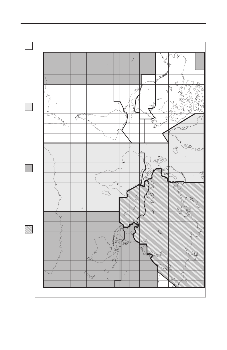
Figure 2-1 KLN 94 Database Geographical Region
SOUTH PAC
PACIFIC
15°
30°
45°
15°
0°
60°
45°
30°
75°
2-0
Page 27

KLN 94 Pilot’s Guide Chapter 2 Data Base
2. DATABASE
2.1. FUNCTIONS OF THE DATABASE
The database provides four primary functions. First, it makes pilot interface with the GPS sensor much easier. Rather than having to manually
look up and then enter the latitude and longitude for a specific waypoint, it
allows you to merely enter a simple waypoint identifier. The database
automatically looks up and displays the latitude and longitude associated
with the identifier. It should be obvious that the database saves a lot of
tedious latitude/longitude entry and also greatly reduces the potential for
data input mistakes.
The second function of the database is that it serves as a very convenient
means to store and easily access aeronautical information. Want to know
the name of the airport, the tower frequency, or the airport elevation? Just
turn the knobs and display the information right on the screen.
Thirdly, the KLN 94 database stores the waypoints in their proper
sequence that comprise most approaches, arrival procedures, and departure procedures. This allows you to select an approach, STAR, and DP by
name as a whole, rather than entering them waypoint by waypoint.
And last but not least, the database furnishes the aeronautical and land
data that is displayed on the color moving map display. It is a great aid in
providing situational awareness to the pilot.
2.2. DATABASE CONTENTS AND COVERAGE AREAS
There are three database coverage areas available for the KLN 94. They
are referred to as the “Americas” database, the “Atlantic International”
database, and the “Pacific International” database.
The International Civil Aviation Organization (ICAO) and Aeronautical
Radio, Inc. (ARINC) break the world into the ten geographic regions
shown in figure 2-1. The KLN 94 Americas database contains aeronautical information for the group of ICAO regions consisting of Canada, USA,
Latin America, and South America. The KLN 94 Atlantic International
database provides information for the ICAO regions Europe, Africa, East
Europe, and Mid East. Likewise, the Pacific International database contains information for East Europe, Mid East, Pacific, and South Pacific.
The KLN 94 database contains three types of data - aeronautical, cartographic (land), and user. Only the aeronautical data is sourced from
Jeppesen Sanderson, Inc. It includes information for airports, navigational
aids, navigational procedures (approaches, STARs, and DPs), and other
aviation specific data. The cartographic data includes land items such as
roads and rivers that can be displayed on the moving map display. User
data is the list of waypoints created by the pilot.
2-1
Page 28

Chapter 2 Data Base
The following is a listing of the KLN 94 database contents:
AERONAUTICAL DATA
AIRPORTS
Identifier
Name
City, State or Country
Use type (if heliports, military, or private)
Latitude and Longitude
Elevation
Runway numbers, lengths, surfaces, and lighting
Fuel availability
Approach types available (precision, non-precision, or none)
Radar approach/departure environment
Time difference relative to UTC.
Airport Communication & Approach frequencies:
ATIS
Clearance delivery
Tower
Ground control
Unicom
Multicom
Approach (IFR)
Departure (IFR)
Class B, Class C, TRSA, CTA, TMA (VFR)
Center (when used for approach)
Arrival
Radar
Director
AWOS (automatic weather observing station)
ASOS (automatic surface observation system)
AAS (aeronautical advisory service)
AFIS (aerodrome flight information service)
ATF (aerodrome traffic frequency)
CTAF (common traffic advisory frequency)
RDO (radio frequency)
MF (mandatory frequency)
Ramp control
PCL (pilot-controlled lighting)
GCO (ground communication outlet)
ILS & LOC type approach
VORs
Identifier
Name
Frequency
Latitude and Longitude
Magnetic variation
2-2
Page 29

KLN 94 Pilot’s Guide Chapter 2 Data Base
NDBs (En Route and Terminal)
Identifier
Name
Frequency
Latitude and Longitude
(Note - Outer Compass Locators may be stored as an NDB by their NDB
identifier or as an intersection by their intersection name)
DMEs associated with ILS/LOC type approaches – Stored with
Intersections by the approach identifier (e.g. IJFK)
Identifier
Latitude and Longitude
Intersections (low altitude, high altitude, DP/STAR, approach, and outer
markers). Also includes DMEs associated with ILS/LOC type approaches.
See DMEs
Identifier
Latitude and Longitude
DP/STAR/Approach Procedures
All compatible pilot-nav DP/STAR procedures
All compatible non-precision and precision approaches. Includes all public GPS-only approaches. Only those non-precision approaches
designated on the Airport 8 page with “GPS” may be used to actually execute an approach with the KLN 94.
Miscellaneous
Air Route Traffic Control Center (ARTCC and FIR) frequencies
Flight Service Stations (location of points of communication and associated frequencies)
Minimum Safe Altitudes
Special Use Airspace (SUA) boundaries-Outer and inner* rIngs
(Prohibited, Restricted, Alert, Class B, Class C, CTA, TMA, TRSA,
Caution, Danger, MOA, Training, Warning)
*ORS 01 and 2 have outer rings only.
LAND DATA
Lakes, rivers, oceans
Roads
Population areas (cities, towns)
Railroads
Political boundaries
Obstacles (towers)
500 USER DEFINED WAYPOINTS
Identifier
Latitude and Longitude
2-3
Page 30

Chapter 2 Data Base
2.3. ICAO IDENTIFIERS
Waypoints are stored in the KLN 94 database almost exclusively by their
ICAO identifiers. ICAO (International Civil Aviation Organization) is an
internationally accepted reference for the data. In almost all cases the
proper ICAO identifiers may be taken directly from Jeppesen-Sanderson
or NOS aeronautical charts.
Airport identifiers in the contiguous United States, Alaska, and Canada are
special cases in the ICAO system. Many airport identifiers for these areas
have four letters beginning with a prefix letter that corresponds to the geographic area in which it is located. The prefix letter for the contiguous U.S.
is “K”. Thus, the identifier for Orlando Executive Airport is KORL while the
VOR identifier is ORL. The prefix letter for Canada is “C” and for Alaska is
“P”.
NOTE: There are several exceptions in Alaska. In many cases, airports
with three letter identifiers receive the prefix “P”, but there are many that
don’t. The most reliable method of determining an Alaska airport identifier
is to look it up from the airport name or city. See section 3.8.3, “Selecting
Waypoints by Name or City”.
Incidentally, you can program the KLN 94 to default to a certain letter
(such as “K”) when you are entering a waypoint identifier. See section
3.4.2, “Data Entry” to learn about this handy feature.
Not all airport identifiers receive the prefix letter. Airport identifiers which
are combinations of letters and numbers do not apply to the prefix rule.
Examples of airport identifiers not using the prefix are 3C2, 70R5, and
M33.
So remember, if you are entering or looking for an airport identifier
that is all letters (no numbers) then it will begin with a “K” prefix in
the contiguous U.S., a “P” in Alaska (in some cases), or a “C” in
Canada. If there are numbers in the identifier then a prefix is not
used. For other areas of the world the airport identifier stored in the
KLN 94 database is identical to how it is charted.
2.4. UPDATING THE DATABASE
The information stored in the database would eventually become obsolete
if there wasn’t some means to update it. For example, new airports open,
navaids can move or change frequency, communication frequencies can
change, new roads are built, and on and on.
NOTE: By FAA regulation, you are required to have a current navigation
database in order to use the KLN 94 for a non-precision approach.
2-4
Page 31

KLN 94 Pilot’s Guide Chapter 2 Data Base
A KLN 94 data card plugs into the left side of the KLN 94 front panel. The
land data resides full time in the data card. The KLN 94 accesses the
land data directly from the data card. The land data can only be updated
by inserting a new data card. New land data is generally available from
Honeywell about once a year.
The aeronautical data is initially contained in the data card. However, this
data is then downloaded automatically into an another memory area internal to the KLN 94. The aeronautical data may be updated by inserting a
new data card or by using a personal computer (PC) to update the internal
memory directly through the data port on the front of the KLN 94. New
aeronautical data is available from Honeywell every 28 days.
The user data is kept in a separate area of internal memory and is not
affected by updating of the aeronautical or land database.
The aeronautical database is designed so that there are three ways for
the user to keep the database current. The first method of database
update is to remove the old data card and insert a current card. This
method involves returning the old card to Honeywell.
The second and third methods involve electronically updating the database by using an IBM-compatible personal computer to update the
internal memory directly via an interface cable that plugs into the data port
on the front of the KLN 94. Method two utilizes Honeywell supplied 3.5inch diskettes with the PC. The diskettes are not returned to Honeywell.
Method three allows for acquiring the update data from the Internet.
Every 28 days, Honeywell receives new NavData™ information from
Jeppesen Sanderson. This information is processed and downloaded
onto both diskettes and database cards. It is also made available to
Internet subscribers. Honeywell makes these three types of update services available to you in a choice of several subscription or random
update programs. See section 2.6 for details on these programs.
NOTE: Honeywell sends the update so that it arrives prior to the next
effective date. The new update may be installed any time prior to the
effective date and the KLN 94 will use the previous data up to the effective
date and automatically begin using the new data on the effective date.
WARNING: The accuracy of the database information is only
assured if it is used before the end of the effectivity period. Use of
out of date database information is done entirely at the user’s own
risk.
2-5
Page 32

Chapter 2 Data Base
2.4.1. COMPUTER UPDATING OF THE DATABASE USING DISKETTES (ORS 02 AND HIGHER UNITS ONLY)
Update information is sent to you on 3.5” disks. In order to use the update
program you must have access to a computer having a disk drive capable
utilizing 3.5-inch 1.44 megabyte high density diskettes. This computer also
needs to have an available COM 1 or COM 2 serial port. If you wish to
perform updates in the cockpit, an optional PC Interface kit must be used.
Included in the kit is an interface cable that plugs into both the computer
and into the data loader jack located on the KLN 94 front panel.
CAUTION: The database must be updated only while the aircraft is
on the ground. The KLN 94 does not perform any navigation function while the database is being updated. Since a database update
takes approximately 8 minutes it is a good idea to turn off all electrical equipment on the aircraft except for the KLN 94 to avoid running
down the aircraft battery.
NOTE: The diskettes sent to you can only be used to update one KLN 94,
although they can update that specific unit numerous times. The first time
the diskettes are used in an update operation, a unique identification code
from the KLN 94 being used is uploaded to the diskettes. These diskettes
may be used in this specific KLN 94 an unlimited number of times which
could be required if you switch back and forth between the Americas,
Atlantic, and Pacific databases during one update cycle. These diskettes
may not, however, be used to update other KLN 94s. This update protection ensures that Jeppesen Sanderson is properly compensated for the
use of their NavData™.
To update the KLN 94 database by computer using diskettes:
1. Plug the 9 pin female connector end of the interface cable into a COM
serial port of the computer. If the computer has COM 1 and COM 2
serial ports, either may be used.
2. If you are using the PC interface kit in the cockpit, plug the other end
of the interface cable (3 conductor male connector) into the data
loader jack that is located on the upper left corner of the KLN 94 front
panel.
3. Insert the diskette into the computer’s disk drive. Turn on the computer being used for the database update. The program on the disk will
automatically “boot” (load) and the computer screen will display
“Ready” when the computer is ready to continue with the database
update operation.
2-6
Page 33

KLN 94 Pilot’s Guide Chapter 2 Data Base
4. Turn on the KLN 94. Press F
as required to approve the Self
Test, Initialization, and Database
pages. Use the right outer knob
to select the Setup (SET) type
pages and the right inner knob to
select the SET 3 page (figure 2-
2).
5. Press B. Update Pub DB?
will now be flashing as in figure
2-3.
6. Press F. The estimated load
time in minutes is now displayed
(figure 2-4).
NOTE: In step 6, repeatedly pressing E will terminate the update
process and bring the display back
to the original SET 3 page shown in
figure 2-2.
7. Press F to acknowledge the estimated load time and begin the
erasing of the existing database.
The unit will now display
Erasing database. After the
database has been erased, the
loading of the new data automatically begins. As the new data is
being loaded, the percentage of
transfer is displayed (figure 2-5).
Figure 2-2
Figure 2-3
Figure 2-4
Figure 2-5
8. The KLN 94 will indicate when
the database update is complete
as shown in figure 2-6. You may
either turn the KLN 94 off at this
point or press F to restart the
KLN 94.
9. Remove the interface cable. Remove the disk from the computer.
Turn off the computer.
Figure 2-6
2-7
Page 34

Chapter 2 Data Base
The chances are small of having difficulty updating the database but—
If you have a problem:
• First check that the interface cable is properly connected and that
the computer is turned on. If there is a problem with the connection
or the computer, the KLN 94 will display Data Loader Not Ready.
When the problem is corrected this prompt is removed and the
update operation can continue from where it left off.
• If an internal test fails after the data has been loaded, the KLN 94
will display Checksum Error, Database Invalid. Press F to
acknowledge. The KLN 94 will then display Database Update
Failed, Retry? Use the right outer knob to position the cursor over
the desired choice and press F.
• There are other error messages that may be displayed. If you have
a problem that you can’t resolve, write down any error messages to
aid your Honeywell Service Center in identifying the problem.
2.4.2 COMPUTER UPDATING OF THE DATABASE USING THE
INTERNET (ORS 02 AND HIGHER UNITS ONLY)
Updates from the Internet can be obtained directly by logging onto the
Honeywell Internet site: www.gpsdatabase.com and following the instructions provided for setting up an account and for doing the update. You
may also call the following telephone numbers to set up an account:
(800) 247-0230
(913) 712-3145
2.4.3 CARD EXCHANGE UPDATING OF THE DATABASE
Having the front-loading data card makes KLN 94 very easy to update the
database by exchanging cards.
Enclose the expired database card in the mailer that the new card was
sent to you in. A return shipping label is included in the mailer. Please
affix this label to the outside of the mailer. Also, peel off the protective
backing from the adhesive on the end flap of the mailer. Press the flap
against the adhesive to seal the container.
Please return the expired card promptly by mailing immediately at any
mailbox. No postage is required if mailed from within the U.S. Users will
be billed for cards not returned and no additional cards will be sent until
either the expired card or payment for the expired card is received.
2-8
Page 35

KLN 94 Pilot’s Guide Chapter 2 Data Base
2.5. USER DEFINED DATABASE
In addition to the aeronautical and land databases, you may create up to
500 other user-defined waypoints. Section 5.4, “Creating User-defined
waypoints” describes this further.
The KLN 94 contains an internal lithium battery that is used to “keep-alive”
the user-defined database as well as flight plans. This battery has a typical life of three to five years. It is highly recommended that the battery be
replaced every three years at an authorized Honeywell Service Center.
2.6. DATABASE UPDATE SERVICE OPTIONS
The following tear-out page can be used for ordering Americas, Atlantic
International, and Pacific International database update services from
Honeywell. The forms may be mailed or FAXed for your convenience.
2-9
Page 36

Chapter 2 Data Base
This page intentionally left blank
2-10
Page 37

UNITED STATES
IN THE
IF MAILED
NECESSARY
NO POSTAGE
Fold here
OLATHE, KS 66061
23500 W. 105 STREET
M D66 - NAVIGATION SERVICES
HONEYWELL INTERNATIONAL INC.
POSTAGE WILL BE PAID BY ADDRESSEE
FIRST-CLASS MAIL PERMIT NO. 121 OLATHE, KANSAS
BUSINESS REPLY MAIL
Tape here
Page 38

KLN 94 Database Update Service Order Form
Consult Pricing Sheet (006-08794-0007) for Service Prices
Honeywell offers several update service
options to suit your requirements. Please
select the service desired, then fill out
and mail this order form. Credit card
orders may be faxed.
Database updates are also available at
www.gpsdatabase.com
Note: Updates are current for 28 days
after effective date on diskette. If you
select any service other than the complete 13-time service, your KLN 94 will
begin alerting you after 28 days that
your data base is out of date.
Check One:
Card Format
Diskette Format
(Laptop Computer Required. See
section 2 of KLN 94 Pilot’s Guide
for details.)
Check Requested Data Base:
Americas Database
Atlantic International Database
Pacific International Database
Check One:
Complete Update Service.
Provides 13 updates–one every 28
days for one year.
Six-time Update Service. Provides
six updates–one every 56 days for
one year.
Four-time Update Service.
Provides four updates–one during
each quarter for one year.
Please set up the service under:
Name:
Company:
Address:
City:
State: Zip Code:
Country:
Telephone: ( )
FAX: ( )
Aircraft Make:
Aircraft Model: ______
Method of Payment
Check/Money order enclosed
Wire Transfer:
Chase Manhattan Bank, NY
Acct #910-2-538734
MasterCard/VISADiscover/AMEX
Number
Expires
Signature
Include sales tax for your state.
Send to:
Single Update. Provides one
update upon receipt of order.
N
Honeywell
Mail Drop #66 - Navigation Services
23500 W. 105th Street
Olathe KS 66061
Phone: 913.712.3145 Fax: 913.712.3904
Toll Free: 800.247.0230
E-mail: nav.database@honeywell.com
www.gpsdatabase.com
Page 39

KLN 94 Pilot’s Guide Chapter 3 Basic GPS Operation
This page intentionally left blank
Page 40

Chapter 3 Basic GPS Operation
PROC
111213151416
KLN 94 TSO
GPS
RNG
CRSR
PUSH ON
BRT
ı
D
1 4 5 6 7 8 9 2 3
MNU
ENTCLRMSG NRSTALTOBS
10
PULL SCAN
Figure 3-1 KLN 94 Controls
Page 41

Chapter 3 Basic GPS Operation
1. On/Off/Brightness knob – Used to turn the unit on and off and adjust
display brightness.
2. Right outer knob – When the cursor is off, used to select the page
type (e.g. APT, NAV, FPL, etc.). When the cursor is on, used to move
the cursor from one position to another on the display.
3. Right inner knob – When the cursor is off, used to select the specific
page number for a page type (e.g. APT 1, APT 2, APT 3, etc.). When
the cursor is on, used to select alphanumerics or other applicable data
for the field the cursor is on.
4. Message button – Used to view messages.
5. OBS button – Used to select between LEG mode and OBS modes
6. Altitude button – Used to select the two Altitude pages where baro
settings are made and VNAV operation is set up.
7. Nearest button – Used to bring up a menu of nearest functions
(Airports, VORs, NDBs, Intersections, etc.) that may be selected.
8. Direct To button – Used to initiate Direct To operation.
9. Clear button – Used to delete data from a data field. Also used to
back up to a previous step in some instances such as selecting
approaches/STARs/DPs
10. Enter button – Used to approve or acknowledge data.
11. Cursor button – Used to turn the cursor on and off.
12. Range button – Used to change the map scale if the map page (Nav
4) page is being displayed. Used to select the map page if it is not
already on the map page.
13. Menu button – Used to display the map menu if the map page (Nav
4) page is being displayed. The map menu is used to initiate changing what is displayed on the map as well as select the map
orientation. Used to select the map page if it is not already on the map
page.
14. Data loader jack – Used when updating the Aeronautical database
from a computer.
15. Procedure button – Used to initiate the loading of approaches, arrival
procedures, and departure procedures. Also used to activate
vector–to–final (VTF) for approaches when an approach with
“Vectors” has been loaded into the active flight plan.
16. Data card – Contains the KLN 94 database.
3-0
Page 42

Page 43

KLN 94 Pilot’s Guide Chapter 3 Basic GPS Operation
3. BASIC GPS OPERATION
This is the first of four chapters specifically dealing with operating the
KLN 94. In this chapter you will learn the basic operation of the front
panel controls and then how to perform Direct To navigation (navigating
from your present position direct to your desired location).
3.1. COVERAGE AREA
The KLN 94 was designed to provide worldwide navigation coverage from
North 74° latitude to South 60° Latitude (figure 3-2). Outside this area,
magnetic variation must be manually entered as discussed in section
4.10, “Operation Outside the Primary Coverage Area”. See section 2.2
for the database geographical regions.
74°
60°
45°
30°
15°
0°
15°
30°
45°
60°
74°
60°
45°
30°
15°
0°
15°
30°
45°
60°
Figure 3-2 KLN 94 Navigation Coverage Area
3.2. TURN-ON AND SELF TEST
Well, it’s time to get down to business and actually use the KLN 94!
Figure 3-1 can be folded out and used as a reference during the following
procedures. This is especially handy if you’re learning while away from
your GPS. The steps below take a lot of words to explain, but before you
know it, you will be “flying” through them.
NOTE: When power is applied to the KLN 94 it always “wakes up” in the
Leg mode. Only the Leg mode is described in this chapter. In this mode
the KLN 94 performs great circle navigation (the shortest distance
between two points located on the earth’s surface). The course deviation
3-1
Page 44

Chapter 3 Basic GPS Operation
output displayed on the unit’s internal course deviation indicator (CDI) and
provided to an external horizontal situation indicator (HSI) or CDI is five
nautical miles (full scale sensitivity) left and right in Leg mode. The other
modes are described in section 5.5 and chapter 6.
To turn on and initialize the KLN 94:
1. Turn on the KLN 94 by pushing in the On/Off/Brightness knob. For the
first few seconds a single color Power-On page is displayed at a fixed
brightness. When the screen changes to full color, rotate the knob to
adjust display brightness to the desired level.
After an additional few seconds,
the operational revision status
(ORS) level number is displayed
on the Power-On page (figure 3-
3). The ORS level displayed
should match the ORS level indicated on the cover of this Pilot’s
Guide .
NOTE: If the temperature is very cold when the KLN 94 is turned on, a
Warm Up screen is displayed after the Power-On screen. Line 4 will display the approximate time the Warm Up screen will be displayed prior to
automatically changing to the Power-On screen. The E button may be
pressed to bypass the Warm Up screen but the display may be extremely
sluggish until it warms up.
Figure 3-3
When an extensive internal test
is complete, the Power-On page
will automatically be replaced by
the Self Test page (figure 3-4).
NOTE: If the KLN 94 is operating in
the Take-Home Mode, the TakeHome Warning Page (figure 3-5) is
displayed first and must be acknowledged by pressing F. See section
3.16 for more information on the
Take-Home mode.
NOTE: A warning page (figure 3-6)
is displayed if the unit is turned on
without a database card.
Figure 3-4
Figure 3-5
Figure 3-6
3-2
Page 45

KLN 94 Pilot’s Guide Chapter 3 Basic GPS Operation
2. Use the right inner knob to enter the current altimeter setting into the
“Baro” field and then press the F button. (If the KLN 94 is interfaced to a compatible airdata system you will not be able to enter data
into this field. Verify that the data displayed on the Self Test page is
the same as is being displayed on the appropriate equipment in the
aircraft which is interfaced to the KLN 94. If the KLN 94 is not connected to any other equipment in the aircraft, you may skip to step 3.
The distance field in the upper left corner always displays 34.5 NM (or
63.9 km). If the KLN 94 is interfaced to a compatible indicator that displays DME distance, the indicator should be displaying 34.5 nautical
miles.
If the KLN 94 is interfaced with a NAV indicator such as an HSI or a
course deviation indicator (CDI), the deviation bar (D-bar) should be
indicating a half scale deviation to the right. The TO/FROM indicator
should be showing FROM.
If the KLN 94 is interfaced with a NAV indicator such that the KLN 94
can “read” the selected course from the NAV indicator, then the OBS
field should display the same selected course as on the NAV indicator.
The RMI field always displays 130 degrees. If the KLN 94 is connected to a compatible RMI in the aircraft, the RMI should indicate a
bearing to the station of 130 degrees.
If any of the above checks fail, do not use the associated indicator
with the KLN 94.
3. If the KLN 94 has passed the internal self test, the bottom of the Self
Test page will display Pass and all external annunciators (if any
installed) should be illuminated. If instead, Fail is displayed, recycle
power to the KLN 94. If the Self Test page still displays Fail, the
KLN 94 requires repair and should not be used for navigation.
4. Use the right outer knob to position the cursor over OK? if it is not
already there. When you are ready to approve the Self-test page,
press the F button.
5. The next page displayed will be
the Initialization page (figure 3-
7). Verify that the date displayed
in the top left corner of the
Initialization page is correct.
Figure 3-7
3-3
Page 46

Chapter 3 Basic GPS Operation
The KLN 94 has an internal battery powered calendar/clock, so the
date and time normally don’t require setting. The battery has a life of
approximately 3 years. In addition, the KLN 94’s system date and time
are automatically updated very precisely when at least one satellite is
being received. However, if for some reason the date or time are
incorrect, it is necessary to enter the correct date or time so that the
KLN 94 can reach the navigation mode quickly. The date should be
correct and the time should be correct within ten minutes so that the
KLN 94 will start looking for the correct satellites.
If the date is incorrect, rotate the
right outer knob counterclockwise until the cursor is over the
entire date field (figure 3-8).
Rotate the right inner knob until
the correct day of the month is
displayed (figure 3-9). Then,
move the cursor to the month
field by rotating the outer knob
one click clockwise and change
the month as necessary. Use the
same methods to select the correct year (figure 3-10). When
the date is correct, press F.
Figure 3-8
Figure 3-9
6. Verify that the time displayed in
the upper right corner of the
Initialization page is correct to
within ten minutes of the actual
time. Remember, once the
KLN 94 receives the first satellite, it will automatically be very
accurately updated by the satellite to the correct time. However,
you are responsible for assuring
the desired time zone is selected
on the KLN 94. If it is necessary
to reset the time, position the
cursor over the time zone field
(figure 3-11) and select the
desired time zone (figure 3-12).
Figure 3-10
Figure 3-11
Figure 3-12
3-4
Page 47

KLN 94 Pilot’s Guide Chapter 3 Basic GPS Operation
The KLN 94 is capable of displaying the following time zones:
UTC Coordinated Universal Time (Zulu)
GST Greenland Standard Time (UTC - 3)
GDT Greenland Daylight Time (UTC - 2)
ATS Atlantic Standard Time (UTC - 4)
ATD Atlantic Daylight Time (UTC - 3)
EST Eastern Standard Time (UTC - 5)
EDT Eastern Daylight Time (UTC - 4)
CST Central Standard Time (UTC - 6)
CDT Central Daylight Time (UTC - 5)
MST Mountain Standard Time (UTC - 7)
MDT Mountain Daylight Time (UTC - 6)
PST Pacific Standard Time (UTC - 8)
PDT Pacific Daylight Time (UTC - 7)
AKS Alaska Standard Time (UTC - 9)
AKD Alaska Daylight Time (UTC - 8)
HAS Hawaii Standard Time (UTC - 10)
HAD Hawaii Daylight Time (UTC - 9)
SST Samoa Standard Time (UTC - 11)
SDT Samoa Daylight Time (UTC - 10)
LCL Local Time Zone (user-defined)
You will be able to change the time zone any time you desire on several other pages, so don’t worry if you’re not sure which time zone to
choose. UTC—Coordinated Universal Time (also called “Zulu”) is
always a safe choice.
The local time zone (LCL) is selected on the SET 2 page, and is
defined to be a certain time offset from Zulu (UTC).
Once you have selected the desired time zone, position the cursor
over the entire time field and select the correct hour with the right
inner knob (figure 3-13). Since
24 hour time is used, be sure to
add 12 if the time is after 1:00
P.M. (2:30 P.M. becomes 1430).
Now move the cursor to the tens
of minutes position and select
the desired value, and repeat
Figure 3-13
3-5
Page 48

Chapter 3 Basic GPS Operation
this process for the last digit of
the time field. When the correct
time has been entered (figure 3-
14), press F to start the clock
running. Don’t worry that you
can’t update the seconds. The
KLN 94 system time will automatically be corrected very precisely once a satellite is received.
7. To aid the GPS receiver in acquiring your position, it helps to have a
reasonable idea of where you are, and the Initialization page is where
you have the chance to set this initial position. Check to see if the displayed initial position is where you actually are. This latitude/longitude
is the last known position before the power was shut down the last
time. Unless the unit has been moved since its last use, this position
should be correct. On the right side of the screen will be the identifier
of the nearest airport in the database, with a radial and distance
from that airport. If you need to
change the initial position to—
let’s say—Omaha Eppley
(KOMA), move the cursor to the
WPT: field and use the right
inner knob to select a K as the
first character of the identifier
(figure 3-15). Move the cursor to
the right one character and
select an O and then right again
to select an M. The final A
should be filled in by the database (figure 3-16). When you
press F, the latitude and longitude fields will change to those
of KOMA (figure 3-17). If necessary, the latitude and longitude
may be entered manually.
Figure 3-14
Figure 3-15
Figure 3-16
Figure 3-17
8. When all information on the Initialization page is correct, move the
cursor to Ok? using the right outer knob and press F to move on.
9. If the KLN 94 installation is approved for VFR use only or for IFR use
without approach capability, a page will be displayed after the
Initialization page to notify you of this.
NOTE: In some installations, KLN 94 is configured for use in IFR En route
and Terminal operations, but not for non-precision approaches. If this is
the case, line 3 will read GPS Approaches Disabled and you will not
have access to approaches in the database.
3-6
Page 49

KLN 94 Pilot’s Guide Chapter 3 Basic GPS Operation
10. The Database page will now be displayed with the cursor over
Acknowledge?. Line 1 indicates whether an Americas, Atlantic
International, or Pacific International aeronautical database is being
used. If the aeronautical database (airports, navaids, approaches, etc)
is current, line 2 will show the date when the aeronautical database
expires (figure 3-18). If the aeronautical database is out of date, line 2
shows the date that it expired (figure 3-19). The KLN 94 will still function with an out-of-date aeronautical database; however, you must
exercise extreme caution and
always verify that the database
information is correct before
using information from an out-ofdate aeronautical database.
Line 3 indicates which database
region is used for the LAND
database (roads, rivers, etc) on
ORS 02 and higher units. Line 4
displays the date that the land
database was created. The
land database has no expiration
date and new data is available
approximately once a year.
Press F to acknowledge the information on the Database page.
The first time the KLN 94 is turned on after a new database card was
inserted, it takes approximately seven minutes to download data from the
card to internal memory. During this time the Database page will temporarily display:
Figure 3-18
Figure 3-19
*STANDBY*
Database being
Updated
When the download is complete the normal database page will be displayed.
WARNING: The accuracy of the database information is assured
only if the database is current. Operators using an out-of-date database do so entirely at their own risk.
NOTE: If your KLN 94 is interfaced
with a remote Shadin fuel/air data
computer but no fuel flow indicator,
the Fuel on Board page will be displayed following the Database page
(figure 3-20). This page allows you to
Figure 3-20
3-7
Page 50

Chapter 3 Basic GPS Operation
set the amount of fuel on board (FOB) and initializes the Auxiliary (AUX)
15 and 16 fuel calculator pages. Possible units are gallons (GAL), pounds
(LB), imperial gallons (IMP), liters (L), or kilograms (KG). If you wish to
manually set the FOB, use the right outer knob to move the cursor to line
2 and use the right inner knob to select the desired value. Another option
is to move the cursor to Full? and press F, which will update the FOB
to the tanks-full value set at the time of installation. To go on, move the
cursor to Ok? and press F.
Either the APT 5 or NAV 1 page will now be displayed on the screen. If
the last active waypoint was an airport, the APT 5 page showing the airport’s communications frequencies will be displayed (figure 3-21). Almost
always, the waypoint which was active when you last turned the KLN 94
off is the airport where you landed. Therefore, when you get ready to
depart, the airport communication
frequencies for that airport will automatically be displayed for you!
Next, you may want to check the
NAV 2 page to see your present
position. Use the right outer knob to
select the NAV page type and then
the right inner knob, if necessary, to
select the NAV 2 page. It is quite
likely that the present position will be
dashed at first (figure 3-22). It takes
the KLN 94 a couple of minutes to
acquire the GPS satellites and to
make its initial calculation of your
position. When the KLN 94 reaches
a NAV ready status and is able to
navigate, the NAV 2 page will display
your present position relative to the
nearest VOR (figure 3-23). Verify
that the present position shown on the NAV 2 page is correct.
Figure 3-21
Figure 3-22
Figure 3-23
NOTE: In order to reach a Nav ready status, the aircraft must be away
from obstructions blocking the GPS antenna’s view of required satellites.
If the KLN 94 fails to reach a Nav ready status within five minutes refer to
section 3.7, “Initialization And Time To First Fix”.
3-8
Page 51

KLN 94 Pilot’s Guide Chapter 3 Basic GPS Operation
3.3. DISPLAY FORMAT
The KLN 94 uses a color LCD. In normal operation, the display screen is
divided into four segments (figure 3-24). When the map page (NAV 4)
page is displayed the page bar is
removed to maximize the height of
the map. Also, in some cases such
as the display of system messages
the segment dividers disappear and
you have a “full-screen” page.
Display Segment 1 (Navigation Data)
A typical display screen is shown in
figure 3-26. Display segment 1 is
the Navigation Data segment. On all
normal pages segment 1 consists of
four lines of data.
• The top line of segment 1
always displays distance to the active waypoint.
• The identifier of the active waypoint is usually displayed on the sec-
ond line.
NOTE: In cases when the active
waypoint identifier is displayed on a
segment 2 page, line 2 will display
the current groundspeed (figure 3-
27).
124
3
Figure 3-24
Figure 3-26
Figure 3-27
• The third line of segment 1 displays the desired track (DTK) when
the KLN 94 is in the LEG mode, its normal mode of operation. DTK
is the course to the active waypoint the aircraft should be flying.
The DTK value will flash if the course selected on the external CDI
or HSI differs from the desired track by more than 10 degrees.
When the KLN 94 is in OBS mode of operation the OBS course is
displayed on line 3. See section 5.5 for modes of operation.
• The aircraft’s actual track (TK) over the ground is displayed on line
four. Displaying the DTK and TK together like this makes it easy to
determine the proper heading to fly in order to make the TK match
the DTK. As long as they match the aircraft will remain on course. If
the TK begins to differ from the DTK it won’t be long until the deviation needle on the CDI or HSI will start be move off center. See
Appendix A for a graphical description of navigation terminology
such as DTK and TK.
3-9
Page 52

Chapter 3 Basic GPS Operation
Display segment 1 changes somewhat when the map page (NAV 4) is
being displayed. See section 3.11.4.
Display Segment 2 (Page)
Aeronautical information is presented on the screen in the form of “pages”.
Segment 2 is where these pages are displayed. A page is a presentation
of specific data in an organized format. Various page “types” are used to
display related kinds of data. For example, one page type is NAV (navigation). NAV pages show information such as distance, groundspeed,
bearing, course, and other data relating to navigation. Another page type
is APT (airport). APT pages contain information pertinent to a specific airport such as name, city, state, elevation, runways, and communication
frequencies.
Display Segment 3 (Page Bar)
The specific page type and number is shown on the page bar at the bottom of the display. Ten page types are shown on the page bar; however,
only the selected page type is shown in reverse video (white characters
on a blue background). In figure 3-27, the NAV 1 (Navigation 1) page is
being displayed in segment 2 and is annunciated as such on the segment
3 page bar.
You might think of the page types as the chapters in a book and the page
numbers as the pages within a chapter. Just as a chapter in a book may
have from one to many pages, a KLN 94 page type may have from one to
26 pages associated with it. There are, for example, 26 flight plan pages
(FPL 0, FPL 1, FPL 2, … FPL 25) in the flight plan page type and up to
eight airport pages (APT 1, APT 2, … APT 8) in the airport page type.
Figure 3-28 shows an example of an
APT 5 page. Notice the “+” sign in
the page identification. Whenever a
“+” sign is part of a page identifier
there will be two or more pages, all
having the same page number, used
to present all of the required information. That is, all of the information
associated with a particular page
number doesn’t fit on the page being
viewed. In this case the “+” sign indicates that there are two or more APT
5 pages. Figure 3-29 shows the second of 10 APT 5 pages for KICT
(Wichita Mid-Continent Airport).
3-10
Figure 3-28
Figure 3-29
Page 53

KLN 94 Pilot’s Guide Chapter 3 Basic GPS Operation
Display Segment 4 (Annunciations)
Segment 4 displays annunciations
associated with the operation of the
KLN 94 (figures 3-30 and 3-31).
Line one shows the WPT (waypoint
alert) annunciation when approaching the active waypoint (see sections
3.10.3 and 4.2.2) or the SCAN
annunciation when the scan function
has been enabled. The scan function
is enabled by pulling the right inner
knob to the “out” position on pages
that allow waypoint lists to be
scanned by turning the right inner
knob.
Line two shows the message prompt, a large “M”, when the KLN 94 has a
message for you to view on the message page (see section 3.5 “Message
Page”). This line is also used to indicate that the KLN 94 is ready for you
to press the F button to approve something, such as a selected waypoint, by flashing the ENT (enter) prompt.
Line three displays a white “VTF” when a vectors-to-final approach has
been loaded into the active flight plan (but not yet activated) and a green
“VTF” when the vectors-to-final approach has been activated (see section
6.2.8).
Figure 3-30
Figure 3-31
Lines four and five display if the unit is in either the approach arm (APR
ARM) or approach active (APR ACTV) modes (see section 6.2.1). The
KLN 94 may also be configured at the time of installation to display terminal (TERM) and approach (APR), respectively, in lieu of APR ARM and
APR ACTV. If the KLN 94 is in the en route mode these lines are blank.
Line six will normally display “LEG” which is the default mode. “OBS” is
displayed when the pilot has selected the OBS mode (see section 5.5
“Navigation Modes”).
Either “LEG” or “OBS” is always displayed on line six. The other lines in
the annunciation segment will be blank unless the annunciation is active.
NOTE: The waypoint alert, message, and approach annunciations may
also be displayed on remote annunciators. See section 3.14 “Remote
Mounted Annunciators”.
3-11
Page 54

Chapter 3 Basic GPS Operation
3.4. BASIC OPERATION OF PANEL CONTROLS
Remember that figure 3-1 is a fold-out page that you may want to refer to
as you read this chapter.
The KLN 94 has three knobs and eleven buttons which are used to perform all operations. Most of the page selection and data entry is done
with the knobs on the right side of the front panel and the cursor (B) button immediately above them.
The cursor position is indicated by an area of reverse video. For example, if the characters are normally green on a black background, the
characters change to black on a green background when the cursor is on.
In figure 3-32 the cursor is over
3000. Many pages allow you to
add, delete, or change data on the
screen by first pressing the B button to turn the cursor function on
and bring the cursor on the screen.
The right knobs are then used to
enter or change data. When the cursor is turned on, the page bar
changes to only show the actual page being displayed in the middle with
*CRSR * on either side. In some cases the cursor will flash to indicate
that the F button must be pressed to approve the data.
Figure 3-32
3.4.1. PAGE SELECTION
It is now time to learn to select a desired page.
NOTE: The cursor function is not used in selecting pages and the B but-
ton should not be pressed at this time. If CRSR is annunciated in page
bar, press the B button to turn the cursor function off.
The right outer knob is rotated to select one of ten page types for the display. These ten page types are the following:
3-12
Page 55

KLN 94 Pilot’s Guide Chapter 3 Basic GPS Operation
Chapter Name/
Page # Range Page Type Page Functions
APT 1-8* Airport Directory of published airports
VOR 1-2 VOR Directory of published VOR stations
NDB 1 NDB Directory of published non-directional beacons (NDB)
INT 1-2 Intersections Directory of published named intersections
USR 0-3 User Waypoint Directory of user-defined waypoints
ACT ** Active Waypoints Information about the active flight plan waypoints
NAV 1-4 Navigation Navigation data
FPL 0-25 Flight Plan Active and stored flight plans
SET 1-14 Setup Setting initial position and date/time, updating the data
AUX 1-14*** Auxiliary Status reports, distance, bearing, time and fuel
* KLN 94's which are not approved for IFR have 6 airport pages.
** Varies with the type of waypoints in the active flight plan.
*** Up to 21 with fuel management system and air data interfaces.
The ten page types are listed across the page bar at the bottom of the
screen. Remember that the page type/number of the page actually selected is shown in reverse video (white characters on a blue background).
The page bar works kind of like a map to get you from one page type to
another. To change page types turn the right outer knob either direction.
The area of reverse video moves across the page bar so that it is always
over one of them. For example, let’s
say you were on a NAV page (figure
3-33) and you wanted to select a
SET page. You would look at the
page bar and see that the SET
pages are two places to the right of
the NAV pages. Therefore, turning
the right outer knob two clicks clockwise will get you to the SET pages
(figure 3-34). The page type selection wraps around from Auxiliary
(AUX) to Airport (APT); that is, the
knob has no mechanical stops.
base, and selecting certain features
calculator; air data calculations based on pilot-entered
inputs and deleting user wpts and remarks
Figure 3-33
Figure 3-34
Once you have selected the desired page type using the right outer knob,
you may select the page number by rotating the right inner knob. So to
change from the SET 1 page to the SET 4 page turn the right inner knob
clockwise three clicks.
Let’s use an example to make sure you understand. You are presently
viewing the APT 2 page and you wish to view the NAV 3 page. Rotating
the right outer knob six clicks clockwise will display the NAV page that you
3-13
Page 56

Chapter 3 Basic GPS Operation
last viewed—we’ll say the NAV 2 page. Turning the right inner knob one
click clockwise or three clicks counterclockwise will bring you to the NAV 3
page. Or, from the APT 2 page you could turn the right outer knob four
clicks counter-clockwise to get to the NAV pages. Got it?
NOTE: In this Pilot’s Guide the right smaller knob is assumed to be in the
“in” position unless it specifically states that the knob should be in the “out”
position. Therefore, the words “rotate the right inner knob” mean to turn
the right inner knob while the knob is in the “in” position.
3.4.2. DATA ENTRY
Now that you’ve learned how to select the desired page, you’re ready to
learn the means of entering data. It is necessary to enter data, for example, in order to specify a waypoint of your choice to go Direct To. The
general procedure for entering a waypoint identifier is described below
and is shown in figures 3-35 through 3-43 for entering a waypoint (in this
case, First Flight airport in North Carolina, identifier KFFA) on the Auxiliary
4 (AUX 4) page.
To enter a waypoint identifier:
1. If the cursor is not on the screen
(figure 3-35), press B to turn
on the cursor function (figure 3-
36).
Figure 3-35
2. If required, rotate the right outer
knob to position the cursor (figure 3-37).
3. Rotate the right inner knob to
select the first character of the
waypoint identifier (figure 3-38).
3-14
Figure 3-36
Figure 3-37
Figure 3-38
Page 57

KLN 94 Pilot’s Guide Chapter 3 Basic GPS Operation
4. Turn the right outer knob one
click clockwise to move the cursor to the second character
position (figure 3-39).
5. Rotate the right inner knob to
select the second character (figure 3-40).
6. Use the right outer and inner
knobs in this manner until the
complete waypoint identifier is
displayed (figure 3-41). Note that
you may not have to enter the
last characters of the identifier
because each time you enter a
character, the KLN 94 offers you
the first identifier in the database
beginning with the characters
you have entered.
7. If ENT is flashing on the right
side of the screen, then press
F. This will prompt the
KLN 94 to display a waypoint
page for the waypoint identifier
you just entered (figure 3-42).
8. Verify the waypoint information
displayed, and then press F
again to approve the waypoint
page. The display will return to
the page previously displayed
(figure 3-43).
Figure 3-39
Figure 3-40
Figure 3-41
Figure 3-42
Figure 3-43
Often, you will find yourself entering airports that begin with the same
character over and over again. In section 2.3, you learned how the
KLN 94 uses ICAO identifiers, which means that many U.S. airport identifiers begin with the letter K. Also, many airport identifiers in Europe begin
with the letter E or the letter L. Especially when flying VFR, you will mostly
want to enter Direct To or Flight Plan waypoints which are airports. You
can set the default first waypoint identifier character on the SET 11 page.
3-15
Page 58

Chapter 3 Basic GPS Operation
To change the default first waypoint identifier character:
1. Select the SET 11 page (figure
3-44) and turn on the cursor by
pressing the B button (figure
3-45).
Figure 3-44
2. Use the right inner knob to select
the desired character (figure 3-
46), such as a K in the U.S., a C
in Canada, a P in Alaska, an E
or an L in Europe, etc.
Figure 3-45
3. Turn off the cursor. To try it out,
proceed to the SET 1 page (initial position). Turn the cursor
(B) on (it will come on over the
waypoint field). Try turning the
right inner knob one click clockwise (figure 3-47). There’s the
character you just selected on
the SET 11 page!
Figure 3-46
4. Turn off the cursor.
3.4.3. THE DUPLICATE WAYPOINT PAGE
There are some waypoints in the database whose identifiers are not
unique. That is, more than one waypoint has the same identifier. When a
waypoint identifier has been entered which is not unique to a single waypoint, a Duplicate Waypoint page appears on the screen. The Duplicate
Waypoint page is then used to select which of the waypoints having the
same identifier is actually desired.
The waypoint identifier is displayed on the top left of the page. Below the
identifier is the number of waypoints in the database having the identifier.
A list of the waypoint types (APT, VOR, NDB, INT, USR) and the associated countries which use the identifier is shown. Some countries such as
the USA are further regionalized (e.g. “NE USA”) to aid in making the correct selection.
NOTE: The duplicate waypoints are displayed in order of closeness to the
aircraft’s present position, the closest being displayed first.
Figure 3-47
3-16
Page 59

KLN 94 Pilot’s Guide Chapter 3 Basic GPS Operation
To see an example of a Duplicate Waypoint page, try entering the identifier “AC” as a Direct To waypoint:
1. Press D.
2. Select “AC” as the waypoint
identifier (figure 3-48). AC is the
full identifier of several waypoints
in the KLN 94 database.
3. Press F. The Duplicate
Waypoint page will be displayed
on the screen (figure 3-49). At
the time of this writing, there
were three waypoints in the
Americas database having the
identifier AC. The list includes an
NDB in the southcentral U.S., an
NDB in the northeast U.S., and an NDB in Canada. The cursor will be
over the first waypoint listed. On the screen in figure 3-49, the NDB in
SC USA is closest to the aircraft’s present position since it is listed
first.
If there are more than four duplicates, view the rest of the choices by rotating the right outer knob clockwise. Doing so will move the flashing cursor
over waypoints two, three, and four and then will cause the waypoint list to
“scroll” so that the other waypoints in the list may be seen.
4. To select the desired waypoint,
move the cursor over the appropriate choice (figure 3-50).
5. Press F and the display will
change to the waypoint page for
the selected waypoint (figure 3-
51).
6. Press F again to approve the
waypoint page.
Figure 3-48
Figure 3-49
Figure 3-50
3-17
Figure 3-51
Page 60

Chapter 3 Basic GPS Operation
3.5. MESSAGE PAGE
Whenever the KLN 94 wants to get your attention, the message prompt (a
large yellow “M” on the right side of
the screen) begins flashing (figure 3-
52). If you have a remote message
annunciator in your aircraft, it will
also begin flashing at that time. You
should view the message at your
earliest opportunity because the unit
may be alerting you to some situation of immediate concern to its condition or to your flight. A description of each possible message is included in
Appendix B of this Pilot’s Guide.
To view a message:
1. Press the C button. The MSG
page will appear and show the
new message (figure 3-53).
NOTE: It is possible that several
messages are displayed at one time
on the Message page. The newest
message appears first and the rest in reverse chronological order.
Figure 3-52
Figure 3-53
2 After reading the message, press C again to return to the page pre-
viously in view. If all of the messages cannot be displayed on one
Message page, repeated presses of C will show the other messages before returning to normal operation. If a message condition
exists which requires a specific action by you, the message prompt
will remain on but will not flash.
3.6 SCRATCHPAD MESSAGES
The lower left corner of the display can also display short operational messages to the user called “scratchpad messages”. These messages are
displayed for approximately five seconds, then this area returns to a display of the page type and number.
Figure 3-54 shows an example of a
scratchpad message indicating an
expired database. A complete listing
of scratchpad messages is available
in Appendix C of this Pilot’s Guide.
Figure 3-54
3-18
Page 61

KLN 94 Pilot’s Guide Chapter 3 Basic GPS Operation
3.7. INITIALIZATION AND TIME TO FIRST FIX
Since the KLN 94 stores its position and other required parameters in
memory when power to the unit is removed, it is seldom necessary to aid
the unit in reaching a NAV ready condition. The time required from power
on until the KLN 94 determines its present position and is therefore ready
to navigate is called “time to first fix.” The time to first fix is normally a few
minutes or less. In order for the KLN 94 to reach a NAV ready condition, it
is necessary to meet the following conditions:
1. The KLN 94’s “almanac” data should be current. Almanac data is
orbital information for all the satellites and is used for initial acquisition
when the KLN 94 is first turned on. This data is stored in the
KLN 94’s non-volatile memory and is considered current for up to six
months. Each satellite sends almanac data for all satellites. Since
the KLN 94 routinely updates the almanac data during normal operation, the almanac data will become out of date only if the KLN 94
hasn’t been used for the previous six months or longer. Collecting
new almanac data takes place automatically if the data is more than
six months old. If the almanac data is out of date and needs to be collected, the KLN 94 will take approximately 12 minutes to acquire your
present position. The Self Test, Initialization, and Database pages
should be approved.
2. The aircraft must be located such that the GPS antenna has an unobstructed view of the sky so that required satellite signals are not being
blocked. If possible, position the aircraft away from hangars or other
obstructions.
3. It is very helpful for the KLN 94 to have the correct time, date and
position to be able to determine which satellites should be in view.
This information is stored in the battery backed memory of the KLN 94
so it is not normally required to update it. If the KLN 94 has the correct
time, date and position, then the time to first fix will usually be less
than two minutes. If this information is not correct, then the KLN 94
will start to look for any satellites. Eventually, the KLN 94 will find
enough satellites to determine the position of the aircraft. This process
can take as long as 12 minutes. It is possible for you to update this
information manually, which will allow the KLN 94 to reach a NAV
ready status much faster. To set the time and date follow steps 5 and
6 in section 3.2, “Turn-On and Self-Test.” The initial position is usually
set during turn-on and self-test, but if for some reason it is necessary
to update the position after the power-on sequence, then use the following steps. Remember, if acquisition time is not important then it is
not necessary to update the time, date or position.
3-19
Page 62

Chapter 3 Basic GPS Operation
To initialize the position from the SET 1 page:
1. If the cursor is not on the screen
(figure 3-55), press the B button to bring it on the page over
the INIT POS field (figure 3-56).
2. Using the right inner and outer
knobs, enter the identifier for the
airport where you are presently
located or the identifier of a
navaid or other airport which is
close to your present position
(figure 3-57). Any waypoint in
the database which is within 60
miles is acceptable, but the closer the better. Remember, if you
are entering an airport identifier
that is all letters (no numbers),
then it will begin with a “K” prefix
in the contiguous U.S., a “P” in
Alaska (in some cases; in others, the prefix is not added), or a “C” in Canada. If there are numbers
in the identifier then a prefix is not used. Outside the contiguous U.S.,
Alaska, and Canada, use the airport identifiers as they are charted.
3. Once you have entered the complete identifier, press F. The
display will change to the waypoint page for the waypoint you
entered (figure 3-58).
4. If this is the waypoint you intended to enter, press F again. The
display will change back to the SET 1 page.
Figure 3-55
Figure 3-56
Figure 3-57
Figure 3-58
NOTE: As an alternative, you can also enter the approximate latitude and
longitude of your present position directly on the SET 1 page instead of
entering a waypoint.
5. With the right inner knob, position the cursor over Ok? if it is
not already there (figure 3-59).
6. Press F to approve the initial
position. The cursor will automatically be removed from the
screen.
Figure 3-59
3-20
Page 63

KLN 94 Pilot’s Guide Chapter 3 Basic GPS Operation
NOTE: If the KLN 94 is in the Take-Home mode, you are allowed to enter
the groundspeed (kt) and heading (°) fields in order to simulate flight (figure 3-60). They are not used for actual initialization in an aircraft.
However, entering a groundspeed
will allow the KLN 94 to “fly” along
the active flight plan (or to a direct to
waypoint) starting from the initialization waypoint. A heading may be
entered in the initial heading field
while in the Take-Home mode if the
one offered is not desired. See section 3.16 for more details on the TakeHome mode.
7. Select the NAV 2 page. When the KLN 94 reaches the NAV ready
status and is therefore able to navigate, the NAV 2 page will display
the present position. Verify that the latitude and longitude or the waypoint, radial, and distance display of present position are correct.
3.8. SELECTING AND SCANNING WAYPOINTS
There are five types of waypoints: airports, VORs, NDBs, intersections,
and user waypoints. Waypoints in the published database fall into one of
the first four types. You can create up to 500 user waypoints to supplement the waypoints in the database (see section 5.4 to create a user
waypoint).
Figure 3-60
There are three methods you may use to select a specific waypoint for
viewing. You may enter the waypoint’s identifier directly, you may scan
through the waypoint identifiers in alphabetical order, or you may enter the
waypoint’s name. If the waypoint is an airport, you may also select it by
entering the city where the airport is located.
3.8.1. SELECTING WAYPOINTS BY IDENTIFIER
The most direct way of selecting a specific waypoint is to simply enter the
waypoint’s identifier directly on the appropriate waypoint page type (APT,
for example). Let’s use Chicago O’Hare International Airport whose identifier is KORD as an example.
To select a waypoint by identifier from a waypoint page:
1. Use the right outer and inner
knobs to select the Airport 1
(APT 1) page (figure 3-61).
(Actually, the airport identifier
can be entered on any of the
Figure 3-61
3-21
Page 64

Chapter 3 Basic GPS Operation
Airport pages but we’ll use the APT 1 since it displays the airport
name and city).
2. Turn on the cursor (B ) and
make sure the right inner knob is
pushed in. The cursor will
appear over the first character of
the airport identifier (figure 3-62).
3. Turn the right inner knob to
select a “K” as the first character
(figure 3-63). You may turn the
knob either clockwise or counterclockwise, and the letters and
numbers wrap around with a
blank character separating the
“9” and the “A”. Notice that as
you turn through letters, the
KLN 94 automatically fills in the
identifier of the first waypoint in
alphanumeric order in the database which matches what you’ve
entered so far (in this case, Hall
Airport in Kaufman, Texas). Go
ahead and experiment a little bit.
Figure 3-62
Figure 3-63
Figure 3-64
4. Use the right outer knob to move
the cursor to the second character and then select an “O” with
the right inner knob (figure 3-64).
5. Use the same process to select
an “R” and then a “D” (figure 3-65). You are now viewing the APT 1
page for KORD.
The KLN 94 feature of filling in characters of the identifier can be a time
saver! For a second example, let’s select Bloomington VOR whose identifier is BMI.
More selecting a waypoint by identifier:
1. Make sure you have turned the
cursor off from the previous
example. With the right knobs,
select the VOR 1 page (figure 3-
66).
2. Turn the cursor (B) on.
Figure 3-65
Figure 3-66
3-22
Page 65

KLN 94 Pilot’s Guide Chapter 3 Basic GPS Operation
3. Change the first character to a
“B” (figure 3-67).
4. Move the cursor to the second
character and select “M” (figure
3-68). Eureka! When you
entered the “M”, the KLN 94
searched its database for the
first VOR identifier beginning
with the letters “BM” and found
BMI. Many times you will only
have to enter two or three characters of the waypoint identifier
and the KLN 94 will furnish the rest.
5. Turn off the cursor (B).
3.8.2. SELECTING WAYPOINTS BY SCANNING
You may also select waypoints by scanning through them. This may be
done with the cursor either on or off.
To select a waypoint by scanning with the cursor off:
1. Select the page type for the
waypoint you are looking for
(APT, VOR, NDB, INT or USR).
Figure 3-67
Figure 3-68
2. Pull the right inner knob to the
“out” position. The SCAN
annunciator will appear (figure 3
– 69).
3. Turn the right inner knob clockwise to scan through the waypoints in
alphabetical order, or counterclockwise to scan in reverse alphabetical
order. Remember that numbers are considered lower in order than
letters. Thus, the airport identifier KA2 comes before KAAF.
NOTE: The faster you turn the knob while scanning, the larger the step
through the waypoints. This variable rate scanning allows you to get from
one end of the list to the other very quickly. When the knob is turned
slowly, you will go through the waypoints one at a time.
You may also want to scan waypoints with the cursor on. This is especially useful if you remember the first part of the identifier, or if you wanted to
scan all airports that start with a KL, for example. Let’s give it a try.
Figure 3-69
3-23
Page 66

Chapter 3 Basic GPS Operation
To select a waypoint by scanning with the cursor on:
1. Select the page type for the waypoint you are looking for (APT, VOR,
NDB, INT or USR). In this case, we want the APT 1 page.
2. Turn on the cursor (B). It will
appear over the first character of
the waypoint identifier. Select a
K with the right inner knob.
3. Move the cursor one place to the
right and select an L (figure 3-
70).
4. Move the cursor one place to the
right and pull the right inner knob
out. The cursor will by over the
last two characters of the waypoint identifier (figure 3-71).
5. Use the right inner knob to leaf
through all the database airports
whose identifiers begin with KL.
You will see KLAA, Lamar
Municipal in Lamar, CO, and
KLAF (figure 3-72), Purdue
University in Lafayette, IN
among others.
Figure 3-70
Figure 3-71
Figure 3-72
3.8.3. SELECTING WAYPOINTS BY NAME OR CITY
When you know the identifier of the desired waypoint you will use one of
the two methods just described to select it. However, what if you know
the name but you don’t know the identifier of your desired waypoint?
You’re in luck because the KLN 94 will allow you to enter the first few
characters of the name to help you find it in the database. We will use a
couple of examples to illustrate how this is done. For VORs and NDBs,
you may use the navaid name. For airports, you may use the airport
name or the city name (where the airport is located).
In this first example we want to view the information in the KLN 94 database for Napoleon VOR (located just east of Kansas City) but we don’t
remember the identifier for it.
3-24
Page 67

KLN 94 Pilot’s Guide Chapter 3 Basic GPS Operation
To select a VOR or NDB by navaid name:
1. With the cursor off, use the right
knobs to select the VOR 1 page
(figure 3-73). The VOR waypoint
in view is not important.
2. Press B and then make sure
the right inner knob is pushed to
the “in” position.
3. With the right outer knob, move
the cursor over the first character in the VOR name which is
being displayed (figure 3-74).
4. Change this first character to an
“N” in this case (figure 3-75).
5. Move the cursor one space to
the right and select the second
character, “A” (figure 3-76).
6. Select the third character, “P”
(figure 3-77). Up pops Napoleon
and its identifier, ANX!
7. Turn off the cursor (B) so you
can view other pages.
We will now use another example to
show how we may enter a few characters and then scan through all the
waypoints in the database beginning
with those characters. Let’s use this
method to find Newport News airport
in Newport News, VA.
Figure 3-73
Figure 3-74
Figure 3-75
Figure 3-76
Figure 3-77
To select an airport by scanning the airport name:
1. With the cursor off and the right inner knob in the “in” position, select
the APT (Airport) 1 page. The airport displayed at this time is not
important.
2. Turn on the cursor (B).
3. Move the cursor over the first
character in the airport name
(figure 3-78).
4. Change the first character to an “N”.
Figure 3-78
3-25
Page 68

Chapter 3 Basic GPS Operation
5. Move the cursor one place to the
right, and select an “E” (figure 3-
79).
6. Enter the “W” and “P” in a similar
manner (figure 3-80).
7. Now, move the cursor one place
to the right of the “P” and pull the
right inner knob out. The rest of
the airport name field will be in
reverse video (figure 3-81).
8. Turn the right inner knob clockwise, scanning through Newport
Municipal in Newport, OR; then
Newport Municipal in Newport,
AR; and then our desired
Newport News, in Newport
News, VA. whose identifier is
KPHF (figure 3-82). By turning
off the cursor (B), pushing the
right inner knob in and turning it,
you can leaf through the remainder of the pages for KPHF.
Figure 3-79
Figure 3-80
Figure 3-81
Figure 3-82
NOTE: This same method may be used with the name of the city where
the airport is located.
There are a few changes made to names in order to accommodate the
KLN 94 display and to make the names easier to find.
1. Names which are too long to fit on the display are abbreviated.
The first six characters are usually exactly correct, but the
following are exceptions:
North, Northern, East, Eastern, etc.—uses N, E
Southeast, Northwest, etc.—uses SE, NW
Point—uses PT
Port—uses PT
Fort—uses FT
Saint—uses ST
General—Deleted, or uses GEN
Person’s name—uses initials for other than last name
unless very well known (Will Rogers World airport)
Delete “City of” (City of Colorado Springs Municipal)
Delete “Greater” (Greater Buffalo Int’l)
Delete “The” (The Hartsfield Atlanta Int’l)
3-26
Page 69

KLN 94 Pilot’s Guide Chapter 3 Basic GPS Operation
2. Unless the first word is greater than eight characters, it is usually
not abbreviated.
3. Delete most punctuation such as periods and apostrophes.
4. Abbreviations for International are INTL, INT, and IN.
5. Abbreviations for Regional are REGL and REG.
3.9. “NEAREST” FUNCTIONS
At any time, you can have access to the nearest airports, waypoints,
Special Use Airspace (SUA), Flight Service Station (FSS) frequencies,
and Center frequencies to your position. Your ticket to do this is the
handy G button.
When you first press the G button,
a page is displayed asking which
nearest function you would like to
select (figure 3-83). The choices
are:
APT Airports
VOR VORs
NDB NDBs
INT Intersections
USR User-defined waypoints
SUA Special Use Airspaces
FSS Flight Service Station Frequencies
CTR Center Frequencies
Figure 3-83
To select the desired nearest function, use the right outer knob to move
the cursor to the desired selection and press F. Notice that the cursor
is initially over the APT field, so you may press G then press F imme-
diately to access the nearest airports.
Selecting any of the waypoint types
(APT, VOR, NDB, INT, or USR)
takes you immediately to the waypoint page for the first nearest
waypoint of that type, for example,
the nearest airport (figure 3-84). The
right inner knob may be pulled to the
“out” position and the inner knob used to scan through the other nearest
waypoints in the list.
Figure 3-84
3-27
Page 70

Chapter 3 Basic GPS Operation
3.9.1. VIEWING THE NEAREST WAYPOINTS
There are actually two waypoint scan lists for airports, VORs, NDBs, intersections and user-defined waypoints. These two lists are the “complete”
list and the “nearest” list. The complete list contains all of the waypoints in
the database for a waypoint type (all the airports, for example). The nearest list consists of the 20 nearest waypoints (of that type) to your present
position. Therefore, if you are in the nearest airport list, it will contain the
20 nearest airports relative to your location.
The nearest list is positioned in front of the complete list. That is, instead
of using the G button, you may also scan backwards (turn the right inner
knob counterclockwise while in the “pulled out” position) through the complete list to reach the nearest list. You will know when you have reached
the nearest list because the top middle portion of the waypoint page will
flash the relative position of the waypoint to your position. “1” indicates
nearest (figure 3-84) while “20” indicates the twentieth nearest (figure 3-
85). As you scan clockwise with the
right inner knob “1, 2, 3, ..., 20”, the
next scan position is the beginning of
the complete list. The nearest list can
only be reached by scanning backwards. It does not wrap around after
the last waypoint in the complete list.
Figure 3-85
Waypoint pages displayed in the nearest list do not contain a latitude and
longitude position as they do in the complete list. Instead, the bearing and
distance to the waypoint (or the radial and distance from the waypoint) are
displayed. In addition, nearest airport pages display the length, surface,
and lighting of the longest runway. Once the nearest waypoint is being
displayed, the other waypoint pages (for example, APT 2 and APT 3) for
that airport are available for display by making sure the right inner knob is
pushed in and then turning it to select the desired airport page.
The nearest list is limited to 200 NM of the aircraft’s present position for all
nearest items except for special use airspace (SUA) which is limited to
175 NM.
3.9.1.1 Nearest Airport Criteria
The 20 airports in the nearest list are the 20 airports which meet the criteria selected on the Setup 4 (SET 4) page. For example, you probably
wouldn’t want to take a turboprop into a 1500 foot grass strip! The SET 4
page allows you to specify what criteria you want an airport to meet before
it is considered for the nearest airport list.
3-28
Page 71

KLN 94 Pilot’s Guide Chapter 3 Basic GPS Operation
To specify the nearest airport criteria:
1. Select the SET 4 page and turn on the cursor (B).
2. Use the right inner knob to
select the minimum length runway desired for the airport to
qualify for the nearest airport list
(figure 3-86). Values between
1000 feet and 5000 feet or
between 300m and 1500m in
100 foot or meter increments may be selected.
3. Rotate the right outer knob clockwise to move the cursor over the runway surface criteria.
4. Turn the right inner knob to select either HRD or ANY. If ANY is chosen, then both hard and soft surface runways meeting the required
runway length will be included in the nearest airport list. If HRD is
chosen, then only hard surface runways will be included. Hard surface
runways include concrete, asphalt, pavement, tarmac, brick, bitumen,
and sealed. Soft surface runways include turf, gravel, clay, sand, dirt,
ice, steel matting, shale, and snow.
For example, if the minimum runway criteria selected is 2200 feet in length
and HRD surface, then only airport having a hard surface runway at least
2200 feet in length will be displayed in the nearest airport list.
Figure 3-86
3.9.1.2 Continuous Display of Nearest Airport
When the nearest airport page is initially displayed, “1” is displayed immediately to the right of the airport identifier to designate this airport as the
nearest airport. However, if you continue to fly along your flight plan with
this page selected, the same airport will be displayed and its position in
the nearest airport list will change from 1 to 2, 3, 4 ... 20 until finally it won’t
be in the nearest airport list at all. The reason for this is that in the event
of an actual emergency once you have determined which airport you are
heading for, you don’t want the nearest airport list to update while you are
maneuvering or looking up data on the other airport pages for that airport.
There may be times, however, when you’re flying over “unfriendly” terrain
when you wish to always have the nearest airport displayed on the
screen.
To display the nearest airport continuously:
1. Display the nearest airport page by pressing G followed by pressing
F.
2. Turn on the cursor (B).
3-29
Page 72

Chapter 3 Basic GPS Operation
3. Rotate the right outer knob
clockwise to position the cursor
over “1” (figure 3-87). As long as
the cursor is left in this position,
this page will update so that the
nearest airport is always shown
as the flight progresses.
3.9.2. VIEWING THE NEAREST SPECIAL USE AIRSPACES
The KLN 94 database stores the locations of areas of special use airspace (SUA). The types of SUA areas stored in the database and the
abbreviations used to denote these areas are the following:
Class B CL B
Class C CL C
Control Area (used outside USA) CTA
Terminal Area (used outside USA) TMA
Alert Area ALRT
Caution Area CAUT
Danger Area DNGR
Military Operations Area MOA
Prohibited Area PROH
Restricted Area REST
Training Area TRNG
Warning Area WARN
Terminal Radar Service Area TRSA
Figure 3-87
The nearest special use airspace feature is constantly keeping track of the
10 nearest areas of SUA within 175 NM of the aircraft’s present position.
Pressing the G button and selecting the SUA option will display the
SUA 1 page for the nearest SUA to your location, including those which
you are inside (figure 3-88). Turn to
section 3.13 “Special Use Airspace
Alerting” to learn more about how an
altitude input affects special use airspace sensing and how the KLN 94
determines if you are inside special
use airspace or not.
The SUA 1 page displays the following information:
Line 1: The name of the special use airspace area.
Line 2: The SUA type (see the list of abbreviations above, this particular
SUA is Class B airspace), and the sequence number (1st nearest, 2nd
nearest, etc.).
Figure 3-88
3-30
Page 73

KLN 94 Pilot’s Guide Chapter 3 Basic GPS Operation
Line 3: The altitude limits of the SUA.
Line 4: The proximity of the nearest point on the border of the SUA, in the
form of the absolute bearing, relative bearing, and distance to the SUA
border. The absolute bearing is the approximate heading you would fly to
most quickly get into the SUA. The relative bearing arrow in the middle of
this line points to the SUA border, telling you if it is directly ahead of you
(↑), straight off your left wing (←), etc. The bearing and distance are not
displayed if the aircraft is inside, above or below an SUA. Finally, the distance to the SUA is displayed on the right side of line 4.
If the aircraft is inside the SUA, line 4 will read *A/C INSIDE SUA*, if you
are above or below the SUA, as indicated by the encoding altimeter, line 4
will indicate this (*A/C ABOVE SUA* or *A/C BELOW SUA*).
A single clockwise turn of the right
inner knob selects the SUA 2 page,
which displays either the controlling
ATC facility (figure 3-89), or if the
special use airspace is a Class B,
Class C, CTA, or TMA, the page will
be displayed as in figure 3-90,
instructing you to press E to see
the APT 5 page (airport communications) for the primary airport so that
the correct communications frequency may be determined.
Figure 3-89
Figure 3-90
To scan through the remainder of the nearest SUA areas, pull the right
inner knob to the “out” position and turn it clockwise to view the SUA
pages for the second nearest through tenth nearest SUAs.
NOTE: The KLN 94 displays the ten nearest SUAs regardless of your
present altitude and the altitude limits of the SUA. For instance, it will
include SUAs specified as “Below 6000ft” even if you are cruising at
10,000 feet.
3.9.3. VIEWING THE NEAREST FLIGHT SERVICE STATION
FREQUENCIES
The KLN 94 stores in its database the locations of Flight Service Stations
(FSS) and their remote communications sites. In addition, the KLN 94
determines which two of these FSS points of communication are closest
to your present location. What a convenience for you! Next time you
want to file a flight plan from the air or contact an FSS for some other reason, you can easily use the KLN 94 to determine a suitable FSS and the
appropriate frequency.
3-31
Page 74

Chapter 3 Basic GPS Operation
NOTE: In some areas of the world the KLN 94 provides the location of
the nearest point of communication with a facility providing information
(INF) or radio (RDO) services.
Pressing the G button and selecting the FSS option will display two of
the nearest points of communication with Flight Service Stations. There
will normally be two FSS 1 pages, one for each of the two points of contact. The name of the FSS is at the top of the page. There can be from
one to three frequencies included for a point of contact (figure 3-91).
Remember that in the U.S. the frequency 122.00 MHz is used for
“Flight Watch” and the frequency
123.60 MHz is used for Aeronautical
Advisory Service. As you know, it is
often possible to communicate with
an FSS by transmitting on 122.10
MHz and listening on the VOR frequency. In cases like this, the FSS 1
page displays the frequencies to use
for transmit and receive and also the
name of the VOR through which you
are communicating (figure 3-92).
The frequencies displayed on the nearest FSS page are QuickTuneTMfrequencies. When the cursor is positioned over a frequency displayed on
this page and the F button is pressed, the frequency is automatically
inserted into the standby window of a Bendix/King KX 155A or KX 165A
Nav/Comm. (QuickTuneTMmust be enabled in the installation for this to be
operational). QuickTuneTMis described in section 3.15.
Figure 3-91
Figure 3-92
3.9.4. VIEWING THE NEAREST CENTER FREQUENCIES
The KLN 94 also stores in its database the low altitude transmitter locations of each of the ARTCC “Centers”. The KLN 94 determines the proper
Center to contact and the appropriate frequencies to use for the aircraft’s
present position. Pressing the G button and selecting the CTR option
will display this information to you (figure 3-93). Next time you wish to
obtain VFR flight following or communicate with Center for any reason,
you have a quick way to get a frequency for establishing contact!
Appendix D contains a listing of
Center abbreviations used on the
CTR page.
NOTE: Frequencies for Area Control Centers are displayed on the CTR
page for some areas of the world.
Figure 3-93
3-32
Page 75

KLN 94 Pilot’s Guide Chapter 3 Basic GPS Operation
The frequencies displayed on the nearest Center page are QuickTune
frequencies. When the cursor is positioned over a frequency displayed on
this page and the F button is pressed, the frequency is automatically
inserted into the standby window of a Bendix/King KX 155A or KX 165A
Nav/Comm. (QuickTuneTMmust be enabled in the installation for this to be
operational). QuickTuneTMis described in section 3.15.
3.10. DIRECT TO OPERATION
The D button is used to initiate Direct To operation (navigation from
your present position direct to your destination). When D is pressed, the
Direct To page will be displayed with
a flashing cursor over a waypoint
identifier (figure 3-94). The waypoint
identifier which appears on the
Direct To page is chosen by the
KLN 94 according to the following
rules:
1. If the Flight Plan 0 (FPL 0) page is displayed on the screen and the
cursor is over one of the waypoint identifiers in FPL 0 when D is
pressed, then that waypoint identifier will appear on the DIR page.
You will appreciate this feature when you learn to use flight plans in
section 4.2.
2. If the KLN 94 is displaying the NAV 4 page and the right inner knob is
in the “out” position, then the waypoint highlighted in the lower right
hand corner of the NAV 4 map display will be the default waypoint.
You will also find this feature useful when operating from the active
flight plan especially during approaches with the KLN 94.
OR . . .
Figure 3-94
TM
3. If there is any waypoint page (APT, VOR, NDB, INT, USR, or ACT
page) in view when D is pressed, then the DIR page will contain the
identifier for the waypoint just viewed.
If none of the conditions above are occurring, then:
4. When D is pressed, the waypoint identifier for the current active
waypoint will be displayed. However, if the KLN 94’s active waypoint
is the Missed Approach Point and the aircraft has flown past the MAP,
then the KLN 94 will display the first waypoint of the missed approach
procedure on the Direct To page.
If there is no active waypoint when D is pressed, then:
5. The Direct To page displays a blank cursor field. In order for there not
to be an active waypoint, there is no Direct To waypoint and there are
no waypoints in Flight Plan 0.
3-33
Page 76

Chapter 3 Basic GPS Operation
3.10.1. INITIATING A DIRECT TO
Now that you know the ground rules, let’s go ahead and try some practical
examples. First, let’s say we wanted to fly directly to Lovell Airport in
Chattanooga, TN. Its ICAO identifier is KCHA.
To fly Direct To a waypoint (procedure 1):
1. Press D. The Direct To page
is displayed (figure 3-95). The
cursor will already be on. A waypoint identifier may or may not
be displayed, it doesn’t matter at
this point.
2. Rotate the right inner knob to
select the first character of the
desired waypoint’s identifier, in
this case, a “K” (figure 3-96).
Remember to enter the “K”, “C”,
or “P” prefix for certain airports in
North America, if required (see
section 2.3, “ICAO Identifiers”).
3. Turn the right outer knob one
click clockwise to move the
flashing portion of the cursor
over the second character position (figure 3-97).
Figure 3-95
Figure 3-96
Figure 3-97
4. Rotate the right inner knob to
select the second character of
the identifier (figure 3-98).
5. Use the right outer and inner
knobs as in the previous steps
until the desired identifier is completely displayed (figure 3-99).
6. Press F to display the waypoint page for the selected
waypoint (figure 3-100).
3-34
Figure 3-98
Figure 3-99
Figure 3-100
Page 77

KLN 94 Pilot’s Guide Chapter 3 Basic GPS Operation
7. Press F again to approve the
displayed waypoint page. The
screen will change to the NAV 1
page, and the selected waypoint
will now be the active Direct To
waypoint (figure 3-101).
NOTE: In some cases during approach operations, the KLN 94 presents a
page asking how a waypoint is used when the waypoint identifier is
entered character by character. When this page is presented, simply
choose the desired use of the waypoint (e.g. FAF or MAHP) by moving
the cursor with the right outer knob and pressing F. Choosing the correct use of the waypoint is required to ensure proper waypoint sequencing
once the aircraft reaches the waypoint.
To fly Direct To a waypoint (procedure 2):
1. Select the desired waypoint
page (APT, VOR, NDB, INT, or
USR) on the screen (figure 3-
102) using one of the three
procedures explained in section
3.8.
2. Press D. The Direct To page
is displayed and it contains the
desired waypoint identifier (figure 3-103).
Figure 3-101
Figure 3-102
3 Press F. The display will
revert to the NAV 1 page with
the selected waypoint as the
Direct To waypoint.
NOTE: There are additional means of more efficiently initiating Direct To
operation when operating from a flight plan. See sections 3.11.4, section
4.2.4.2, and section 4.2.4.3.
To recenter the D-Bar by going direct to the active waypoint:
If you get off course and wish to recenter the left/right deviation bar (DBar) to proceed to the same waypoint, use the following procedure.
1. Select a non-waypoint page (NAV, FPL, SET, or AUX) on the screen.
2. Press D. The Direct To page is displayed on the left, containing the
active waypoint identifier.
3. Press F.
Figure 3-103
3-35
Page 78

Chapter 3 Basic GPS Operation
NOTE: If the KLN 94 is in the approach mode and this method is used to
center the D-bar when the missed approach point is the active waypoint,
then the approach mode will be cancelled and the KLN 94B will revert to
the approach arm mode.
3.10.2. CANCELLING A DIRECT TO
The primary reason for wanting to cancel Direct To operation is to return
to flight plan operation which is described later in section 4.2.4 “Combining
Direct To and Flight Plan Operation”. When the Direct To operation is
cancelled the KLN 94 orients itself on the closest leg of the active flight
plan (FPL 0).
To cancel Direct To operation:
1. Press D.
2. Press E to blank out the waypoint identifier field (figure
3-104).
3. Press F.
3.10.3. WAYPOINT ALERTING FOR DIRECT TO OPERATION
The purpose of waypoint alerting is to notify you that you are approaching
the active waypoint (the Direct To waypoint in this case). Approximately
36 seconds prior to reaching a Direct To waypoint the WPT annunciation
at the top of the annunciation display segment will begin flashing (figure 3-
105). If an external waypoint alert (WPT) annunciator is mounted in the
aircraft, this annunciator will begin
flashing at the same time. In addition, the arrow preceding the
waypoint identifier on the waypoint
page for the active waypoint will
begin flashing. This arrow will also
be flashing on any NAV or FPL page
displaying the active waypoint identifier.
Figure 3-104
Figure 3-105
3-36
Page 79

KLN 94 Pilot’s Guide Chapter 3 Basic GPS Operation
3.11. NAVIGATION PAGES
As you would expect, the NAV (navigation) pages contain information
relating specifically to the KLN 94’s navigation capabilities. The KLN 94
has four NAV pages. The procedure for selecting specific pages, including
the NAV pages, was described in section 3.4.1, “Page Selection”.
3.11.1. THE NAVIGATION 1 (NAV 1) PAGE
The NAV 1 page is shown in figure
3-106.
Line 1: The active navigation leg.
For Direct To operation this consists
of the Direct To symbol, $, followed
by the active Direct To waypoint
identifier (figure 3-106). For the leg of
a flight plan this consists of the
“from” waypoint identifier and the
active “to” waypoint identifier (figure
3-107). An arrow ∆ precedes the
active waypoint identifier.
Line 2: A course deviation indicator (CDI) that graphically displays left
and right deviation from desired course. The CDI’s vertical bar operates
like a navigation deviation needle on a conventional CDI or HSI using
VOR/Localizer navigation. An on-course indication is displayed when the
vertical deviation bar is centered on the triangle in the middle of the CDI.
In en route use, each dot represents one nautical mile deviation from the
desired track (full scale deviation is ± 5 NM). Different CDI scales are used
during terminal and non-precision approach flight with KLN 94. For now,
let’s talk only about en route operations. A vertical deviation bar positioned two dots to the
right of the center triangle indicates the
aircraft is two nautical
miles to the left of
course (figure 3-108).
The center triangle
also serves as the
CDI’s TO/FROM indicator and operates in
the same manner as a
conventional CDI
TO/FROM indicator; a
triangle pointing up
indicates “to” the
CNU
2 NM
TUL
Figure 3-106
Figure 3-107
Figure 3-108
3-37
Page 80

Chapter 3 Basic GPS Operation
active waypoint while a “down” triangle (figure 3-109) indicates “from” the
active waypoint. The word FLAG is
displayed over the CDI when the
KLN 94 is not usable for navigation
(figure 3-110).
Line 3: Numeric crosstrack correction – the crosstrack distance (how
far off course) and direction to fly to
intercept the desired track. The
numeric crosstrack correction distance display is especially handy
when more than five nautical miles
off of course. If your crosstrack distance was 13.1 nautical miles left of
course, the graphic CDI needle will
be pegged on the right side (which
doesn’t tell you much). But this presentation will show you exactly how
far off course you are (figure 3-111).
The CDI scale factor is also displayed on line 3. This is the full scale deviation. Normal en route CDI scale factor is ± 5 NM which means each dot
represents 1 NM of deviation off course. The CDI scale factor may be
changed as described in section 5.6. “Changing The CDI Scale Factor.”
Figure 3-109
Figure 3-110
Figure 3-111
Line 4: VNAV status, which will either by Off, Armed, time until VNAV
begins, or the suggested VNAV altitude (see section 5.2. “Advisory VNAV
Operation.”
Line 5: A data field which can display either bearing to the active waypoint (To) or radial from the active waypoint (Fr). By placing the cursor
over this field and turning the right inner knob you may select which of
these is displayed. Line 5 also displays the estimated time en route (ETE)
from present position to active waypoint.
NOTE: Due to “great circle” courses and magnetic variation differences
between present position and the active waypoint, the To bearing and
From radial may not be exactly 180° different from each other when the
system is in the Leg mode. This condition is most likely to occur when
long distances are involved, and/or you are operating in very northerly or
southerly latitudes. See figure 3-112 for an example depicting a case like
this. The aircraft is somewhere over Georgia, and the active waypoint is
KPHX. The bearing to steer is 269°, and radial is 72°. Generally, you will
want to use bearing (not radial) when long distances are involved.
3-38
Page 81

KLN 94 Pilot’s Guide Chapter 3 Basic GPS Operation
N
72°
KPHX
N
269°
Figure 3-112
3.11.2. THE NAVIGATION 2 (NAV 2) PAGE
The NAV 2 page in figure 3-113 displays the aircraft’s present position in
two formats: (1) the radial and distance from a nearby VOR and (2)
latitude and longitude. You can
change the reference waypoint from
Figure 3-113
the nearby VOR to any waypoint in the published or user database.
To change the NAV 2 page present position reference waypoint:
1. Turn on the cursor (B). It will
be over the Ref: field (figure 3-
114).
2. Use the right inner and outer
knobs to enter the waypoint you
Figure 3-114
wish to use as a reference.
3. Press F. The waypoint page
for the identifier just entered will
be displayed.
4. If this is the waypoint you intend-
Figure 3-115
ed, press F again. The
display will return to the NAV 2 page (figure 3-115).
NOTE: If you change the reference waypoint, change to a page other than
the NAV 2 page, then turn back to the NAV 2 page, the reference waypoint will revert back to a nearby VOR.
NOTE: Your present position may be easily stored as a user-defined waypoint by pressing F while viewing the NAV 2 page. See section 5.4.1,
“Creating A Waypoint At Your Present Position.”
3-39
Page 82

Chapter 3 Basic GPS Operation
3.11.3. THE NAVIGATION 3 (NAV 3) PAGE
The Navigation (NAV) 3 page shows
you several important times pertaining to your flight (figure 3-116).
Line 1: The current system time
zone and the actual time. The time
zone may be changed by turning the cursor (B) on over it and turning
the right inner knob. All times shown on the NAV 3 page are in terms of
the system time zone (except for the flight time and ETE, which are periods of time).
Line 2: The time of departure. This is the time when a valid groundspeed
was first greater than 30 knots (typically during takeoff).
Line 3: The elapsed flight time, which will be the hours and minutes since
the departure time.
Line 4: The estimated time en route to the destination.
Line 5: Estimated time of arrival (ETA) at your destination. If the active
waypoint is not part of the active flight plan, the active waypoint will be the
destination. Otherwise, the last waypoint in your active flight plan will be
the destination.
3.11.4. THE NAVIGATION 4 (NAV 4) PAGE – MOVING MAP
The NAV 4 page is a graphical moving map which offers you excellent
“bird’s-eye-view” situational awareness. This page shows the aircraft’s
present position relative to the route of flight, aeronautical data, and cartographic (land) data. The aeronautical data includes things like airports,
VORs, NDBs, intersections, and special use airspace. Land data includes
items such as cities, roads, bodies of water, geographical boundaries,
obstacles, and railroad tracks. User waypoints may also be displayed on
the map.
Figure 3-116
CAUTION: There are land data items that may not be dispayed on the
map or may not be displayed accurately in position. Do not depend
on the land data displayed on the map as the sole means of identifying or avoiding land data items.
3.11.4.1 Selecting The NAV 4 (Map) Page
In addition to the normal way of selecting pages with the right knobs, the
NAV 4 page may be instantly displayed by pressing either the map range
(R) button or the map menu (M) button. Once the NAV 4 page is displayed these buttons are used to change the map scale and to bring up
the map menu, respectively.
3-40
Page 83

KLN 94 Pilot’s Guide Chapter 3 Basic GPS Operation
3.11.4.2 NAV 4 Page Format
The NAV 4 page has a unique format unlike any other KLN 94 page
(figure 3-117). The page bar is
removed on the NAV 4 page to utilize the maximum screen height for
the map. The page being displayed,
NAV 4, is shown in the bottom right
corner of the screen.
Display segment one, on the far left side of the screen, now has five lines
rather than four lines on the other pages. It displays the following:
• Line 1 - Distance to the active waypoint
• Line 2 - Active waypoint identifier
• Line 3 - Desired track (DTK) in the LEG mode or OBS course in the
OBS mode. The DTK value flashes if the course selected on the
external CDI or HSI differs from the desired track by more than 10
degrees.
• Line 4 - Actual track (TK), bearing to active waypoint (BRG), radial
from active waypoint (RAD), or groundspeed
• Line 5 - Groundspeed, estimated time en route (ETE) to active way-
point, cross track error, or vertical navigation (VNAV) status
Figure 3-117
Lines 4 and 5 can be configured by the pilot to display any of the items
listed.
To configure lines 4 and 5 to display the desired Navigation items:
1. Press B to turn on the cursor.
2. Rotate the right outer knob counterclockwise to position the
cursor over the desired line (figure 3-118)
3. Rotate the right inner knob to
select the desired item (figure 3-
119).
4. Press B to turn off the cursor
when done
Figure 3-118
Figure 3-119
3-41
Page 84

Chapter 3 Basic GPS Operation
3.11.4.3. Selecting What Is Shown On The Map
The aircraft’s present position symbol and route of flight are always selected for display on the map. The map range scale will determine how much
of the route is displayed.
When operating Direct To a waypoint which is not in the active flight plan,
the Direct To waypoint and its associated course line are shown on the
map, and although the waypoints of
the active flight plan (FPL 0) are
shown on the screen, they are not
connected by course lines (figure 3-
120).
When you are navigating with a flight
plan the NAV 4 page displays the
waypoints of the active flight plan
with their waypoint identifiers (figure
3-121). Course lines connect the
flight plan waypoints. The course line
to the active waypoint is magenta,
other course lines are white.
Other items of interest to the pilot may also be selected for display on the
map. These fall into two basic categories, aeronautical (aero) data and
land data. It would be easy to put so much on the map that it is impossible to read. Therefore it is important to configure the map to display those
items which are most important to you.
Figure 3-120
Figure 3-121
3.11.4.4. Configuring Aeronautical Data For The Map
The SET 7 page is used to configure the aeronautical data for the map.
The following items may be configured on this page:
• Nearest 10 areas of special use airspace (SUA) within 175 NM of
the aircraft. Only those SUA types selected on the SET 6 page will
be displayed. See section 3.13 “Special Use Airspace Alerting.”
Inner rings for Class B, Class C, TMA and CTA airspace are displayed up to the 30 NM range (ORS 03 and higher units).
• Nearest 20 VORs within 200 NM of the aircraft
• Nearest 20 airports (APT) within 200 NM of the aircraft. Only those
airports meeting the criteria selected on the SET 4 page are displayed.
• Nearest 20 intersections (INT) within 200 NM of the aircraft. (The
default setting for intersections is “OFF” to avoid clutter. This may
be changed as described below.)
• Nearest 20 NDBs within 200 NM of the aircraft
3-42
Page 85

KLN 94 Pilot’s Guide Chapter 3 Basic GPS Operation
• Nearest 20 user defined waypoints (USR) within 200 NM of the air-
craft
• Tower rings (TWR Rings). A tower ring is a 4 NM radius circle
drawn around airports having a control tower that operates at least
part time. Note that a tower ring is not Class D airspace which
usually consists of a 3 to 7 NM radius ring plus additional
extensions. Tower rings are not displayed for the primary airport
associated with class B, class C, CTA, or TMA airspace.
• Holding Patterns and Procedure Turns (Hold Pat) associated with
approaches, DPs and STARs. (ORS 02 and higher)
Each of the above items may be turned on or off individually. The item is
turned on by selecting the maximum map range scale you want the item
to be displayed. Therefore if the 5 NM map range scale is selected for
intersections, the intersections will be displayed on the map for range
scales 5 NM and smaller and will not be displayed on the map for range
scales greater than 5 NM.
To configure aeronautical data for the map:
1. Press the M button while viewing the NAV 4 map page to bring
up the map menu. The cursor
will already be over “Setup Aero
Data?” (figure 3-122).
2. Press the F button. This
brings up the SET 7 page (figure
3-123).
NOTE: All aeronautical data may
be turned off by using the right outer
knob to position the cursor over the
field to the right of “AERO DATA: “
and then using the right inner knob
to select “OFF” (figure 3-124).
Figure 3-122
Figure 3-123
3. Use the right outer knob to position the cursor over the field next
to the item to be configured.
Lines 4 and 5 are a scrolling
region so after positioning the
cursor over the VOR field, further clockwise turns of the knob
will scroll down the list. To configure intersections, position the
cursor over the distance field to
the right of INT (figure 3-125).
3-43
Figure 3-124
Figure 3-125
Page 86

Chapter 3 Basic GPS Operation
4. Rotate the right inner knob to
select the desired range (figure
3-126). Range scales greater
than that selected will not display
the selected item. Range scales
equal to or less than that selected will display the item.
5. Use the right inner and outer knobs to finish configuring the rest of the
aeronautical items for the map.
6. Press the R button or M button to return to the map.
NOTE: Each aeronautical item has a factory set default range value. To
change an individual item to the default value place the cursor over the
range field to the right of the desired item and press the E button. To
change all aeronautical items to their default ranges, place the cursor over
“Restore Dfaults?” on line 3 and press the F button.
3.11.4.5. Runway Diagrams
If the selected map range scale is 5 NM (7 km) or less, runway diagrams
are depicted along with the airport symbol.
3.11.4.6. Configuring Land Data On The Map
Figure 3-126
The SET 8 page is used to configure the land data for the map. The following items may be configured on this page:
• Cities/towns – large, medium, and small
• Roads – freeways, national highways, local highways
• Lakes and Rivers
• Railroads
• Geographical boundary lines
• Obstacles – towers less than1000 ft. AGL and those 1000 ft. AGL
and greater
NOTE: At the time this Pilot’s Guide was written, obstacle data is only
available for the United States.
Each of the above items may be turned on or off individually. The item is
turned on by selected the maximum map range scale you want the item to
be displayed.
3-44
Page 87

KLN 94 Pilot’s Guide Chapter 3 Basic GPS Operation
To configure land data for the map:
1. Press the M button while viewing the NAV 4 map page to bring
up the map menu.
2. Turn the right outer knob clockwise to position the cursor over
“Setup Land Data?” (figure 3-
127).
3. Press the F button. This
brings up the SET 8 page (figure
3-128).
NOTE: All land data may be turned
off by using the right outer knob to
position the cursor over the field to
the right of “LAND DATA: “ and then
using the right inner knob to select
“OFF” (figure 3-129).
4. Use the right outer knob to position the cursor over the field next
to the item to be configured.
Lines 4 and 5 are a scrolling
region so after positioning the
cursor over the Med City field,
further clockwise turns of the
knob will scroll down the list. To
configure Lakes, position the
cursor over the distance field to
the right of Lakes: (figure 3-130).
Figure 3-127
Figure 3-128
Figure 3-129
Figure 3-130
Figure 3-131
5. Rotate the right inner knob to select the desired range (figure 3-131).
Range scales greater than that selected will not display the selected
item. Range scales equal to or less than that selected will display the
item.
6. Use the right inner and outer knobs to finish configuring the rest of the
land items for the map.
7. Press the R button or M button to return to the map.
NOTE: Each land item has a factory set default range value. To change
an individual item to the default value place the cursor over the range field
to the right of the desired item and press the E button. To change all
land items to their default ranges, place the cursor over “Restore Dfaults?”
on line 3 and press the F button.
3-45
Page 88

Chapter 3 Basic GPS Operation
3.11.4.7. Symbols Used On The Map
The following symbols are used on the Nav 4 map page:
Aircraft symbol
Active flight plan or direct to leg (magenta)
Inactive flight plan leg (white)
VFR airport (cyan)- ORS O1 only
IFR airport (green)- ORS 01 only
VFR airport (cyan) One or more hard surface runways
VFR airport (cyan) No hard surface runway
VFR airport (cyan) No runway information
IFR airport (green) One or more hard surface runways
IFR airport (green) No hard surface runway
IFR airport (green) No runway information
VOR with no distance
VOR/DME or VORTAC
DME-usually assoc. with ILS/LOC type procedures
NDB
Intersection
User waypoint
Special Use Airspace-Prohibited/Restricted areas (red)
Special Use Airspace-other (green)
Notes
Shows approximate orientation of longest hard surface runway. ORS 02 and higher.
Shows approximate orientation of longest runway. ORS 02 and higher.
These airports will not be displayed on map unless they are part of active flight plan. ORS 02 and higher.
Tower ring
Geographical boundary
City
Freeway (Americas Database)
National highway (Americas Database)
Local highway (Americas Database)
Freeway (Intl Databases)
National highway (Intl Databases)
Local highway (Intl Databases)
Railroad
River
Lake
Obstacle 1000 ft. or greater AGL
Obstacle less than 1000 ft. AGL
3.11.4.8. Selecting The Map Orientation
All KLN 94 installations are capable of three map orientations: actual track
up (TK↑), North up (N↑), and desired track up (DTK↑). In addition, if the
KLN 94 is interfaced with a compatible source of heading then a heading
up presentation (HDG↑) may also be selected.
In the actual track up orientation, viewing the map is like looking at a chart
that is turned so that the direction the aircraft is tracking over the ground is
pointing up. In a no-wind condition actual track is identical to the aircraft’s
heading. The aircraft must be moving at least two knots to calculate the
actual track. The map will be blank at any speed less than two knots.
When the North up orientation is selected, viewing the map is like looking
at a navigation chart with North at the top. The aircraft symbol rotates
based on the aircraft’s actual track (or heading if available). If the KLN 94
does not have a heading input and the aircraft is not moving the aircraft
symbol is replaced by a “+” symbol.
If desired track is selected, the map is like looking at a chart that is turned
so that the course line is always pointing up.
3-46
Page 89

KLN 94 Pilot’s Guide Chapter 3 Basic GPS Operation
The heading up mode orients the map with the aircraft’s heading as up.
The heading up orientation is not presented as a choice if heading is not
provided to the KLN 94.
If a heading input is available to the KLN 94 then heading up is usually the
best map orientation to select. Otherwise, actual track up display is usually preferred for use in flight. However, since the track up display is only
usable when the aircraft is moving two knots or more the North up display
may be a good choice if you are stationary.
CAUTION: When using the actual track up format it is typical for
there to be a slight delay from the time a heading change is made
until the correct map orientation is displayed. Be careful when using
either the desired track up display or the actual track up display to
not think that a heading up display is being used.
To change the map orientation:
1. Select the NAV 4 (map) page if
not already displayed. The easiest way to do this is to press
either the map range (R) button
or the map menu (M) button.
2. Press the M button to display
the Map Menu page (figure 3-
132).
Figure 3-132
3. Rotate the right outer knob
clockwise to position the cursor
over the map orientation (figure
3-133).
4. Select the desired map orientation by turning the right inner
knob (figure 3-134).
5. Press the R button or M button to return to the map using the selected orientation.
3.11.4.9. Changing the Map Range Scale
The map range scale is displayed in the bottom left corner of the map.
The number displayed is the distance in nautical miles from the aircraft’s
present position symbol to the top of
the screen. The 10 NM scale is
selected in figure 3-135. Press the
upper portion of theRbutton to
increase the range scale and the
bottom portion to decrease the range
Figure 3-133
Figure 3-134
Figure 3-135
3-47
Page 90

Chapter 3 Basic GPS Operation
scale. The scale may be changed from 1/2 NM to 1000 NM (or 1 km to
2000 km if km selected as distance unit on SET 12 page).
In addition, an “AUTO” scale mode may be selected so that the map scale
automatically changes to display the active waypoint and, if there is one,
the next waypoint after the active waypoint (figure 3-136).The AUTO map
scale may be selected in two ways: 1) by pressing either portion of the R
button continuously for 2 seconds, or
2) by repetitively pressing the R
button either one step “below” the
1/2 NM (1 km) or “above” 1000 NM
(2000 km) until “AUTO” is displayed.
The AUTO scale mode is especially
useful when using the KLN 94 for
approaches.
Z
The overzoom icon is displayed
when the selected map scale range
is beyond the accuracy of the stored
land data (figure 3-137). This occurs
at small map scale ranges and
means that land data positions may
not be accurately displayed.
Remember, it is easy to clutter the display with so much data that it is
unusable. Select a range scale that allows an uncluttered presentation of
the chosen aeronautical and land data. Or, select another combination of
these starting from the Map Menu page. Experiment and continue to
make new selections for different phases of your trip.
Figure 3-136
Figure 3-137
3.11.4.10 Decluttering The Screen
The map may be temporarily decluttered by pressing the E button to
make it easier to view the active
flight plan waypoints or the Direct To
waypoint. The first press of the E
button turns off the land data and an
“-L” annunciation is shown above the
map range scale (figure 3-138). A
second press of the E button
removes the aeronautical data and
an “-A” annunciation is also displayed (figure 3-139). The land and
aeronautical data may be brought
back by pressing the E button
again or by leaving the map page and returning to it. The E button only
declutters what has been turned on from the SET 7 and SET 8 pages.
Figure 3-138
Figure 3-139
3-48
Page 91

KLN 94 Pilot’s Guide Chapter 3 Basic GPS Operation
When the KLN 94 goes into the approach active mode all land data,
except for bodies of water, is automatically decluttered from the map. A
“-L” is then annunciated. In the approach active mode the first press of
the E button restores land data and subsequent presses work as
described in the previous paragraph.
3.11.4.11. Waypoint Scan Feature
The NAV 4 page’s waypoint scan feature may be used as an easy way to
initiate Direct To operation to the active waypoint, active flight plan (FPL 0)
waypoints, or waypoints from the nearest list without leaving the map
page. This feature is also useful for quickly accessing a waypoint page for
a waypoint displayed on the map. To utilize the waypoint scan feature:
1. Pull the right inner knob to the
“out” position. The identifier of
the active waypoint will be displayed in the waypoint scan field
located in thethe lower right corner of the map (figure 3-140).
2. Rotate the right inner knob
clockwise or counter-clockwise
to select the desired waypoint
(figure 3-141). FPL 0 waypoints
and the Direct To waypoint are
displayed in green while other
waypoints are displayed in white
to make it easy to determine the
break from the FPL 0 list to the
nearest list (figure 3-142). The
waypoints are displayed in the
following order.
• A Direct To waypoint not in FPL 0 (if one exists)
Figure 3-140
Figure 3-141
Figure 3-142
• The FPL 0 waypoints
• A list of the nearest waypoints viewable on the map (airports,
VORs, NDBs, intersections, user waypoints). This list includes only
those that meet the requirements specified on the SET 6 and SET 7
pages. For example, if the map scale is currently at 60 NM but you
chose to view NDBs only up to 5 NM on the SET 7 page, the NDBs
will not appear on the map and will not be in the waypoint scan list.
These nearest waypoints are all grouped together and presented in
order of closeness to the aircraft’s present position. Therefore,
when scanning through the nearest list you may go from an airport,
to an intersection, to a VOR, etc.
3-49
Page 92

Chapter 3 Basic GPS Operation
3. (ORS 02 and higher) If the waypoint displayed in the scan field is
actually displayed on the map, its map icon is encircled on the map
(figures 3-141 and 3-142). Waypoints that are located close together
on the map are easy to uniquely identify using this feature. In addition,
a line is drawn from the aircraft symbol toward the waypoint even if
the waypoint is not actually displayed on the map.
4. To initiate a Direct To operation to the waypoint in the scan field press
the D button (figure 3-143). Press the F button to complete the
Direct To operation. Press the
inner knob back to the “in” position. This procedure may be
used on any waypoint in the
scan field.
OR
5. To bring up the waypoint page
for the waypoint in the scan field,
press the F button (figure 3-
144). This feature is nice if you
want to identify an airport or
navaid that appears on the map but is not in your flight plan.
NOTE: This feature is not available for waypoints associated with DPs,
STARs, and approaches. If the F button is pressed while a DP, STAR,
or approach waypoint is in the waypoint scan field a scratchpad message
stating “NO WPT Page” will be displayed.
Figure 3-143
Figure 3-144
6. Press the R or M button to return to the map.
3.11.4.12. Holding Patterns And Procedure Turns (ORS 02 and
higher)
The KLN 94 map is capable of displaying holding patterns associated
with DPs, STARs, and approaches
as well as procedure turns associated with approaches (figure 3-145).
The KLN 94 does NOT provide complete navigational guidance for these
procedures. It is necessary to use the OBS mode to navigate relative to
the inbound leg of holding patterns and the inbound/outbound legs of procedure turns. The pilot is required to fly the headings published on the
instrument approach charts for the other parts of the holding pattern or
procedure turn.
Holding patterns and procedure turns associated with approaches are
only displayed on the map when the appropriate approach transition or
missed approach procedure has been loaded into the active flight plan.
Figure 3-145
3-50
Page 93

KLN 94 Pilot’s Guide Chapter 3 Basic GPS Operation
For example if an approach has three IAFs but only one of the IAFs utilizes a procedure turn, the procedure turn will only be displayed when the
one IAF is selected. In addition it is necessary to select a maximum map
range scale to display holding patterns and procedure turns on the SET 7
page (see section 3.11.4.4).
CAUTION: Fly the published procedure for conducting procedure
turns and holding patterns. Do not rely solely on the depicted procedure on the map as it may not be depicted to the proper scale.
Holding patterns and procedure turns are sized on the map according to
the aircraft’s groundspeed. The radius of turns is based on standard rate
turn using the aircraft’s groundspeed. Therefore as the aircraft’s groundspeed changes due to the aircraft’s configuration or the effect of the wind
the size of the pattern will change. Holding patterns defined with fixed distance legs (e.g. 2 NM legs) are depicted with the defined leg length.
3.12. WAYPOINT PAGES
NOTE: Each of the waypoint page types includes a field which displays
present magnetic bearing to or magnetic heading from the waypoint. Due
to “great circle” courses and magnetic variation differences between present position and the active waypoint, the To bearing and From radial may
not be exactly 180° different from each other. This condition is most likely
to occur when long distances are involved, and/or you are operating in
very northerly or southerly latitudes. See section 3.11.1 and figure 3-112
for more details.
3.12.1. AIRPORT PAGES
3.12.1.1. The Airport 1 (APT 1) Page
See figure 3-146.
Line 1: The ICAO identifier (see
section 2.3) of the airport; an arrow
precedes the identifier if it is the
active waypoint. The airport elevation above MSL in feet or meters,
which is rounded to the nearest 10 feet or nearest meter.
Line 2: The name of the airport.
Line 3: The city where the airport is located.
Line 4: The state if the airport is located in the U.S., the Province if locat-
ed in Canada, or the country if outside the U.S. and Canada. A listing of
the abbreviations used for States, Provinces, and countries is contained in
Figure 3-146
3-51
Page 94

Chapter 3 Basic GPS Operation
Appendix D. The right side of line 4
will read HELIPORT if applicable,
MILITARY if it is a military airport
(Figure 3-147), and PRIVATE if it is
a private use airport.
If the airport is being viewed as part
of the nearest airports list (see section 3.9.1, “Viewing the Nearest
Waypoints”), the APT 1 page format
will differ as follows (see figure 3-
148):
Line 1: After the airport identifier,
the number designating the airport’s position in the nearest airport list is
displayed. In figure 3-148, KLIT is the third nearest airport.
Line 2: Same as a normal APT 1 page.
Line 3: The length, surface and lighting of the longest runway.
Line 4: The magnetic bearing to or the magnetic radial from the airport
and the distance. Placing the cursor over the radial/bearing field and turning the right inner knob changes it between radial from and bearing to the
airport.
Figure 3-147
Figure 3-148
3.12.1.2. The Airport 2 (APT 2) Page
See figure 3-149.
Line 1: The ICAO identifier (see
section 2.3) of the airport; an arrow
precedes the identifier if it is the
active waypoint.
Lines 2-3: The latitude and longitude of the airport reference point (the
“official” location of the airport).
Line 4: The magnetic bearing to or the magnetic radial from the airport
and the distance. Placing the cursor over the radial/bearing field and turning the right inner knob changes it between radial from and bearing to the
airport.
If the airport is being viewed as part
of the nearest airports list (see section 3.9.1, the APT 2 page format
will differ as follows (see figure 3-
150):
Line 1: After the airport identifier, the number designating the airport’s
position in the nearest airport list is displayed.
Figure 3-149
Figure 3-150
3-52
Page 95

KLN 94 Pilot’s Guide Chapter 3 Basic GPS Operation
Line 2: The city where the airport is located.
Line 3: The state if the airport is located in the U.S., the Province if locat-
ed in Canada, or the country if outside the U.S. and Canada. A listing of
the abbreviations used for States, Provinces, and countries is contained in
Appendix D. The right side of line 3 displays HELIPORT, MILITARY, or
PRIVATE as appropriate.
Line 4: The magnetic bearing to or the magnetic radial from the airport
and the distance. Placing the cursor over the radial/bearing field and turning the right inner knob changes between radial from and bearing to the
airport.
3.12.1.3. The Airport 3 (APT 3) Page
See figure 3-151.
Line 1: The ICAO identifier (see
section 2.3) of the airport; an arrow
precedes the identifier if it is the
active waypoint. Also on line 1 is the
environment. For example, the airport in figure 3-151 has overlying Class C airspace. The possible
environments are:
CL B Class B airspace
CL C Class C airspace
CTA Control area
TMA Terminal area
TRSA Terminal radar service area
Figure 3-151
Line 2: The airport’s time difference from UTC during standard time and
during daylight time (in parentheses).
Line 3: Fuel types available at the airport. This line will be blank if there
is no fuel available at the airport.
80 80 octane
100 100 octane
100L 100 octane, low-lead
JET Jet fuel (of any type)
AUTO Automotive fuel (also known as MOGAS)
Line 4: Approach type(s) available at the airport. If an airport has an ILS
approach and/or an MLS approach, no indication of non-precision
approach availability will be given.
NO APR No IFR approach
NP APR Non-precision approach(es) only
ILS ILS approach
3-53
Page 96

Chapter 3 Basic GPS Operation
MLS MLS approach
ILS/MLS ILS and MLS approaches
If the airport has a GPS approved non-precision approach included in the
KLN 94 database, GPS will also be displayed on line 4.
The lower right corner will display (R) if the airport has an approach/departure radar environment.
3.12.1.4. The Airport 4 (APT 4) Page
See figure 3-152
The APT 4 page displays the runway
designation, length, surface, and
lighting for up to five runways in
order of length, beginning with the
longest runway. Since there are
many times when all of an airport’s runway information does not fit on one
page, additional APT 4 pages are used to display the data. Remember
that a “+” inserted between the page type and the number (APT+4 in this
case) is used to indicate that there is more than one Airport 4 page.
Line 1: The ICAO identifier (see section 2.3) of the airport; an arrow precedes the identifier if it is the active waypoint.
Figure 3-152
Line 2: The runway designation for the first runway on the page.
NOTE: In some parts of the world, runway numbers are based on true
runway heading rather than magnetic. These runways are prevalent in
northern Canada, where there is a large magnetic variation gradient. For
these runways, a Tsymbol separates the two runway numbers (example
14T32).
Line 3: The runway length for the first runway listed on the page, the runway surface type and the type of lighting (blank if none).
Runway surface abbreviations:
HRD Hard surface
TRF Turf
GRV Gravel
CLY Clay
SND Sand
DRT Dirt
SNW Snow
ICE Ice
SHL Shale
MAT Steel mat
3-54
Page 97

KLN 94 Pilot’s Guide Chapter 3 Basic GPS Operation
Runway Lighting Abbreviations:
L Sunset to sunrise
LPC Pilot controlled lighting
LPT Part-time or on-request lighting
Lines 4-5: Runway information for the next shortest runway (if any), in
the same format as lines 1 and 2.
In the event that there is no runway information for an airport, the following
message is displayed on the APT 4 page:
No Runway Data
3.12.1.5. The Airport 5 (APT 5) Page
See figure 3-153.
Line 1: The ICAO identifier (see
section 2.3) of the airport; an arrow
precedes the identifier if it is the
active waypoint.
Lines 2-5: The VHF communication frequencies associated with the airport. Also, frequencies for ILS and LOC-type approaches at the airport.
The type and frequency are listed.
Figure 3-153
All communication and navigation frequencies are QuickTuneTMfrequencies which means that pressing the F button with the cursor over the
frequency sends the frequency to the standby window of a KX 155A or
KX 165A Nav/Com if this feature is enabled in the installation (see section
3.15 “QuickTuneTMNav/Com Frequency Selection”). In order to make the
QuickTuneTMfeature even easier to use, lines 2-5 are a scrolling region
when there is more than one APT 5 page (designated by APT+5). What
this means is that you can turn on the cursor on the first APT 5 page and
use the right outer knob to move the cursor through all the frequencies for
all this airport’s APT 5 pages without having to turn the cursor on and off
while you change between APT 5 pages.
The communication abbreviations are:
AAS aeronautical advisory service
AFIS aerodrome flight information service
ARVL arrival
APR approach
ASOS automated surface observation system
ATF aerodrome traffic frequency
ATIS automatic terminal information service
AWOS automatic weather observing station
CL B class B airspace (VFR frequency)
3-55
Page 98

Chapter 3 Basic GPS Operation
CL C class C airspace (VFR frequency)
CLR clearance delivery
CTA control area (VFR frequency used outside the U.S.)
CTAF common traffic advisory frequency
CTR center (when center is used for approach/departure
DEP departure
DIR director (approach control/radar)
GCO ground communications outlet
GRND ground control
MCOM multicom
MF mandatory frequency
PCL pilot-controlled lighting
PTAX pre-taxi clearance
RAMP ramp/taxi control
RDO radio
RDR radar-only frequency
TMA terminal area (VFR frequency used outside the U.S.)
TWR control tower
UNIC unicom
The Navigation abbreviations are:
ILS Instrument landing system approach
LOC Localizer approach
LBC Localizer back course
LDA Localizer type directional aid approach
SDF Simplified directional facility approach
control)
Part-time operation, such as for a control tower, is indicated with an asterisk (*) to the right of an airport frequency.
The frequencies associated with class B or C airspace, CTA or TMA are
VFR frequencies. Airports which have one of these categories of frequencies also have APR and DEP which are IFR frequencies.
Where required, APR, DEP, CL B, CL C, CTA, and TMA frequencies are
sectorized. That is, a frequency may be used only within a certain range
of radials from a designated reference location. The format for displaying
the sectorization is to show the frequency first, followed by the identifier of
the associated reference point, followed next by the associated altitude
restrictions. For example, figure 3154 shows that the Orlando
approach control frequency 121.10
MHz is used between the 311° radial
Figure 3-154
3-56
Page 99

KLN 94 Pilot’s Guide Chapter 3 Basic GPS Operation
and the 60° radial from KMCO (Orlando International Airport) for altitudes
at and below 5500 feet.
In a few cases, APR, DEP, CL B, CL C, CTA, and TMA frequencies are
sectorized such that the restrictions cannot be displayed on a single page.
When this occurs the following message is displayed on the APT 5 page:
Text Of Freq Use
Not Displayed
3.12.1.6. The Airport 6 (APT 6) Page
The Airport 6 page is used to store
and display user-entered remarks.
These remarks might include information on lodging, dining, airport
services, etc. Up to 200 waypoints
(airports and user waypoints combined) may include remarks. See figure 3-155.
Line 1: The ICAO identifier (see section 2.3) of the airport; an arrow precedes the identifier if it is the active waypoint.
Lines 2-4: The pilot-entered remarks for the airport. Three lines of 16
characters each are available for the remarks. Letters, numbers, hyphens,
and spaces may be used in the remark. If no remarks have been entered
for the airport, line 2 will display “[Remarks]”.
Figure 3-155
To enter an airport remark on the APT 6 page:
1. Turn on the cursor and move it
until the cursor fills line 2 of the
screen (figure 3-156).
2. Select the desired character with
the right inner knob and move
the cursor to the next character
on the line with the right outer
knob (figure 3-157).
3. Repeat step 2 as necessary to
complete line 2.
4. Press F to approve line 2. The
cursor will automatically move to
the next line (see figure 3-158).
5. Use the right inner and outer
knobs to complete line 3. The
F button must be pressed to
approve line 3 separately.
3-57
Figure 3-156
Figure 3-157
Figure 3-158
Page 100

Chapter 3 Basic GPS Operation
6. Use the right inner and outer
knobs to complete line 4. The
F button must be pressed to
approve line 4 separately.
7. Turn the cursor off when you are
finished creating the remark (figure 3-159).
NOTE: If there are already 200 waypoints with remarks and an attempt is
made to enter a remark for a waypoint, a scratchpad message “Remarks
Full” is displayed. It is then necessary to delete remarks using the AUX
13 page before new remarks can be entered.
The Auxiliary 13 (AUX 13) page is a list of waypoints with associated
remarks. If you wish to delete a waypoint remark for an airport it is done
from the AUX 13 page, see section 5.11.
3.12.1.7. The Airport 7 (APT 7) Page
The APT 7 page shows the departure (DP) and arrival (STAR)
procedures that are available for the
selected airport. If both DP and
STAR procedures are available then
there will be two APT 7 pages indicated by APT+7 (figure 3-160). If
there are no DP or STAR procedures
in the database then this page will be
as shown in figure 3-161.
NOTE: If the KLN 94 is configured
for VFR use only there will not be an
APT 7 page.
Figure 3-159
Figure 3-160
Figure 3-161
Line 1: The ICAO identifier (see section 2.3) of the airport; an arrow precedes the identifier if it is the active waypoint. “DP” is displayed for the list
of departure procedures and “STAR” is displayed for the list of arrival procedures.
Lines 2-5: List of the DPs or STARs. If there are more than four procedures, the final one in the list is on line 5 on the screen. To view the
procedures that are not in view, turn on the cursor with the B button and
turn the right outer knob clockwise.
3-58
 Loading...