

Page 1

SYSTEM INSTALLATION
Preliminary - Subject to Change Without Notice
MANUAL
KHF 1050
HF COMMUNICATION SYSTEM
MANU AL NUMBER 006-10640-0000
REVISION 0, March 2003
Page 2

WARNING
Preliminary - Subject to Change Without Notice
PRIOR THE EXPORT OF THIS DOCUMENT, REVIEW FOR EXPORT LICENSE
REQUIREMENT IS NEEDED.
COPYRIGHT NOTICE
©2003 Honeywell International Inc.
REPRODUCTION OF THIS PUBLICATION OR ANY PORTION THEREOF BY ANY MEANS
WITHOUT THE EXPRESS WRITTEN PERMISSION OF HONEYWELL IS PROHIBITED. FOR
FURTHER INFORMATION CONTACT THE MANAGER, TECHNICAL PUBLICATIONS,
HONEYWELL, ONE TECHNOLOGY CENTER, 23500 WEST 105TH STREET OLATHE KS
66061 TELEPHONE: (913) 782-0400.
Page 3

N
Preliminary - Subject to Change Without Notice
System Installation Manual
P/N 006-10640-0000
KHF 1050
HF Communication System
(Also known as Primus HF 1050)
KAC 1052 Antenna Coupler
KPA 1052 Power Amplifier
KRX 1053 Receiver/Exciter
Compatible HF Control Units
Revision 0 T-1
10640I00.SLK Mar/2003
23-10-09
Page 4

N
Preliminary - Subject to Change Without Notice
KHF 1050 SYSTEM INSTALLATION MANUAL
REVISION HISTORY
KHF 1050
SYSTEM INSTALLATION MANUAL
23-10-09
-----------------------------------------------------------------
PART NUMBER
006-10640-0000 0 Mar/2003 Original issue.
REV DATE DESCRIPTION
Revision 0 RH-1
10640I00.SLK 23-10-09 Mar/2003
Page 5

N
Preliminary - Subject to Change Without Notice
KHF 1050 SYSTEM INSTALLATION MANUAL
REVISION HISTORY
KHF 1050
SYSTEM INSTALLATION MANUAL
23-10-09
-----------------------------------------------------------------
PART NUMBER
REV DATE DESCRIPTION
Revision 0 RH-2
10640I00.SLK 23-10-09 Mar/2003
Page 6

N
Preliminary - Subject to Change Without Notice
KHF 1050 SYSTEM INSTALLATION MANUAL
RECORD OF REVISIONS
REV.
NO.
REVISION
DA TE
DA TE
INSERTED
BY
REV.
NO.
REVISION
DA TE
DA TE
INSERTED
BY
Revision 0 RR-1
10640I00.SLK 23-10-09 Mar/2003
Page 7

N
Preliminary - Subject to Change Without Notice
KHF 1050 SYSTEM INSTALLATION MANUAL
RECORD OF REVISIONS
REV.
NO.
REVISION
DA TE
DA TE
INSERTED
BY
REV.
NO.
REVISION
DA TE
DA TE
INSERTED
BY
Revision 0 RR-2
10640I00.SLK 23-10-09 Mar/2003
Page 8

N
Preliminary - Subject to Change Without Notice
KHF 1050 SYSTEM INSTALLATION MANUAL
COMMENTARY: LEP TO BE UPDATED UPON COMPLETION OF MANUAL
LIST OF EFFECTIVE PAGES
SUBJECT PAGE DATE SUBJECT PAGE DATE
Title T-1 Mar/2003
T-2 Mar/2003
Revision RH-1 Mar/2003
History RH-2 Mar/2003
Record of RR-1 Mar/2003
Revisions RR-2 Mar/2003
List of Effective Pages LEP-1 Mar/2003
LEP-2 Mar/2003
Table of Contents TC-1 Mar/2003
TC-2 Mar/2003
Introduction INTRO-1 Mar/2003
INTRO-2 Mar/2003
Glossary G-1 Mar/2003
G-2 Mar/2003
G-3 Mar/2003
G-4 Mar/2003
Description and 1 Mar/2003
Operation 2 Mar/2003
3 Mar/2003
4 Mar/2003
5 Mar/2003
6 Mar/2003
7 Mar/2003
8 Mar/2003
9 Mar/2003
10 Mar/2003
11 Mar/2003
12 Mar/2003
13 Mar/2003
14 Mar/2003
15 Mar/2003
16 Mar/2003
Installation and 2001 Mar/2003
Maintenance 2002 Mar/2003
2003 Mar/2003
2004 Mar/2003
2005 Mar/2003
2006 Mar/2003
2007 Mar/2003
2008 Mar/2003
2009 Mar/2003
2010 Mar/2003
2011 Mar/2003
2012 Mar/2003
2013 Mar/2003
2014 Mar/2003
2015 Mar/2003
2016 Mar/2003
2017 Mar/2003
2018 Mar/2003
2019 Mar/2003
2020 Mar/2003
2021 Mar/2003
2022 Mar/2003
2023 Mar/2003
2024 Mar/2003
2025 Mar/2003
2026 Mar/2003
2027 Mar/2003
2028 Mar/2003
2029 Mar/2003
2030 Mar/2003
2031 Mar/2003
Testing and 1001 Mar/2003
Faul t Isolation 1002 Mar/2003
F INDICATES FOLDOUT PAGES - PRINT ONE SIDE ONLY
Revision 0 LEP-1
10640I00.SLK
23-10-09 Mar/2003
Page 9

N
Preliminary - Subject to Change Without Notice
KHF 1050 SYSTEM INSTALLATION MANUAL
COMMENTARY: LEP TO BE UPDATED UPON COMPLETION OF MANUAL
LIST OF EFFECTIVE PAGES
SUBJECT PAGE DATE SUBJECT PAGE DATE
F 2125 Mar/2003
2126 Blank
F INDICATES FOLDOUT PAGES - PRINT ONE SIDE ONLY
Revision 0 LEP-2
10640I00.SLK
23-10-09 Mar/2003
Page 10

N
Preliminary - Subject to Change Without Notice
KHF 1050 SYSTEM INSTALLATION MANUAL
COMMENTARY: TOC TO BE UPDATED UPON COMPLETION OF MANUAL
TABLE OF CONTENTS
INTRODUCTION
SECTION PAGE
1. General INTRO-1
2. Layout of Material INTRO-1
3. Revision Service INTRO-1
DESCRIPTION AND OPERATION
SECTION PAGE
1. System Description 1
A. System Overview 3
B. System Component Descriptions 4
C. Component Installation Kits 5
D. Equipment Required But Not Supplied 6
E. Optional (Non-Essential) Aircraft Equipment 8
F. Related Publications 8
2. Component Configurations 9
A. KAC 1052 Antenna Coupler Configurations 9
B. KPA 1052 Power Amplifier Configurations 9
C. KRX 1053 Receiver/Exciter Configurations 9
D. RM-855 Radio Management Unit Configurations 9
E. MCDU Multifunction Control and Display Unit Configurations 9
F. PS440 Control Display Unit Configurations 9
G. ???? Antenna Configurations 9
H. Long Wire HF Antenna Configurations 9
3. System Leading Particulars 10
A. General Specifications 10
B. System Operating Modes 10
C. Component Leading Particulars 13
4. System Function 15
A. System Functional Overview 15
B. Dual System 16
5. Component Functions 16
A. RM-855 Radio Management Unit Function 16
B. MCDU Multfunction Control and Display Unit Function 16
C. PS440 Control Display Unit Function 16
6. System Inputs/Outputs 17
A. Input/Output Signals 17
TABLE
COMMENTARY: ALL SECTION TABLES TO BE LISTED HERE AS THEY ARE INSERTED.
FIGURE
COMMENTARY: ALL SECTION FIGURES TO BE LISTED HERE AS THEY ARE INSERTED
PAGE
PAGE
Revision 0 TC-1
10640I00.SLK 23-10-09 Mar/2003
Page 11

N
Preliminary - Subject to Change Without Notice
KHF 1050 SYSTEM INSTALLATION MANUAL
COMMENTARY: TOC TO BE UPDATED UPON COMPLETION OF MANUAL
TABLE OF CONTENTS
TESTING AND FAULT ISOLATION
SECTION PAGE
1. Fault Isolation 1001
2. System Performance Check 1002
A. Preliminary Check 1002
B. Receiver Performance Check 1002
C. Transmitter Performance Check 1002
INSTALLATION AND MAINTENANCE
SECTION PAGE
1. General Coverage 2001
2. Unpacking 2001
3. Pre-installation Testing 2001
4. Equipment Changes and Markings 2002
5. Installation Planning 2002
A. General Considerations 2002
B. Location of Equipment 2002
C. Interwiring and Cable Fabrication 2017
D. Strapping Options 2052
6. Equipment Installation 2055
A. Bonding Connections 2055
B. KCU 951 Control Unit Installation 2056
C. KFS 594 Miniature Control Unit Installation 2056
D. KA 594 Bus Adapter Installation 2056
E. KCU 1051 Control Display Unit Installation 2056
F. KAC 952 Power Amplifier/Antenna Coupler Installation 2057
G. KTR 953 Receiver/Exciter Installation 2061
H. Antenna Installation 2062
I. KA 161 External Capacitor Installation 2063
J. KA 158 Bridging Amplifier Installation 2064
K. KA 160 Dual Antenna Adapter Installation 2064
L. KA 162 Dual External Capacitor Installation 2065
7. Inspection, System Checkout, and Flight Test Procedures 2065
A. Inspection 2065
B. System Checkout 2068
C. Flight Test 2068
8. Removal and Re-installation 2069
A. KCU 951 Control Unit Removal and Re-installation 2069
B. KFS 594 Miniature Control Unit Removal and Re-installation2069
C. KA 594 Bus Adapter Removal and Re-installation 2069
D. KCU 1051 Control Display Unit Removal and Re-installation 2069
E. KAC 952 Power Amplifier/Antenna Coupler Removal 2070
F. KTR 953 Receiver/Exciter Removal and Re-installation 2070
G. KA 98 Antenna Removal and Re-installation 2071
H. KA 161 External Capacitor Removal and Re-installation 2072
I. KA 158 Bridging Amplifier Removal and Re-installation 2073
J. KA 160 Dual Antenna Adapter Removal and Re-installation 2074
K. KA 162 Dual External Capacitor Removal and Re-installation2074
Revision 0 TC-2
10640I00.SLK 23-10-09 Mar/2003
Page 12

N
Preliminary - Subject to Change Without Notice
KHF 1050 SYSTEM INSTALLATION MANUAL
COMMENTARY: TOC TO BE UPDATED UPON COMPLETION OF MANUAL
TABLE OF CONTENTS
9. Maintenance Procedures 2075
A. In-Aircraft Adjustments 2075
B. System Protection 2075
C. Lubrication 2076
D. Cleaning 2076
10. System Maintenance Programs 2076
A. System Maintenance Recommendations 2076
B. Field Alignment of KTR 953 Receiver/Exciter (-51, -53) 2076
TABLE
COMMENTARY: ALL SECTION TABLES TO BE LISTED HERE AS THEY ARE INSERTED.
FIGURE
COMMENTARY: ALL SECTION FIGURES TO BE LISTED HERE AS THEY ARE INSERTED
PAGE
PAGE
Revision 0 TC-3
10640I00.SLK 23-10-09 Mar/2003
Page 13

N
Preliminary - Subject to Change Without Notice
KHF 1050 SYSTEM INSTALLATION MANUAL
COMMENTARY: TOC TO BE UPDATED UPON COMPLETION OF MANUAL
TABLE OF CONTENTS
Revision 0 TC-4
10640I00.SLK 23-10-09 Mar/2003
Page 14

KHF 1050 SYSTEM INSTALLATION MANUAL
Preliminary - Subject to Change Without Notice
1. General
This manual provides description and operation, testing,
fault isolation, installation, maintenance, and flightline
checkout procedures for the KHF 1050 HF Communication System.
2. Layout of Manual
Section 1 Description and Operation
Section 1000 Testing and Fault Isolation
Section 2000 Installation and Maintenance
Refer to the Table of Contents for the location of applicable
information.
Weights and measurements in the manual are in English units,
unless otherwise stated.
N
INTRODUCTION
3. Revision Service
The manual will be revised as necessary to reflect current
information. Service Bulletins may be issued separately, and
will be incorporated in the manual as appropriate.
Revision 0 INTRO-1
10640I00.SLK Mar/2003
23-10-09
Page 15

N
Preliminary - Subject to Change Without Notice
KHF 1050 SYSTEM INSTALLATION MANUAL
Blank Page
Revision 0 INTRO-2
10640I00.SLK Mar/2003
23-10-09
Page 16

N
Preliminary - Subject to Change Without Notice
KHF 1050 SYSTEM INSTALLATION MANUAL
Glossary of Terms and Abbreviations
A/C Aircraft
AGC Automatic Gain Control
AME Amplitude Modulation Equivalent
ARM The ready to operate status of a function/device.
CFR Clarifier
CLK Clock
COMP Compatible
CPLR Coupler
GND Ground
HF High Frequency
LCD Liquid Crystal Display
LSB Lower Side Band
MCDU Multifunction Control and Display Unit
MIC Microphone
NVG Night Vision Goggles
ORTHOGONAL Intersecting at right angles.
PA Power Amplifier
PROC Processing, Processor
PEP Peak Envelope Power
PTT Push To Talk
PWR Power
RC Reduced Carrier
RCVR Receiver
RDY Ready
REF Reference
RF Radio Frequency
Revision 0 G-1
10640I00.SLK Mar/2003
23-10-09
Page 17

N
Preliminary - Subject to Change Without Notice
KHF 1050 SYSTEM INSTALLATION MANUAL
Glossary of Terms and Abbreviations
RMU Radio Management Unit
RTCA Radio Technical Commission for Aeronautics
RTN Return
RX Receive
SELCAL SELective CALling
SELECTIVITY The ability of a receiver to differentiate desired
RF signals from undesired signals and other
disturbances within specified frequency and dB
limits.
SENSITIVITY The ability of a receiver to detect and demodulate
desired signals at specified minimum RF levels.
SIDETONE The small portion of the transmitter signal that is
fed back to the receiver’s audio circuit.
SIG Signal
SQUELCH The ability to disable the demodulated output of a
radio receiver until a preset level of RF input is
received. The level of received RF signal required
to break squelch is determined by the squelch
control setting.
SSB Single Side Band
SYN Synthesize(r), Synchronize(r)
TCXO Temperature compensated crystal oscillator
TRANLINE Transmission Line
TX Transmit
USB Upper Side Band
VOL Volume
VSWR Voltage Standing Wave Ratio
XCTR Exciter (low level signal source that drives power
amplified transmitted signal).
XMT Transmit
XMTR Transmitter
Revision 0 G-2
10640I00.SLK Mar/2003
23-10-09
Page 18
N
Preliminary - Subject to Change Without Notice
KHF 1050 SYSTEM INSTALLATION MANUAL
DESCRIPTION AND OPERATION
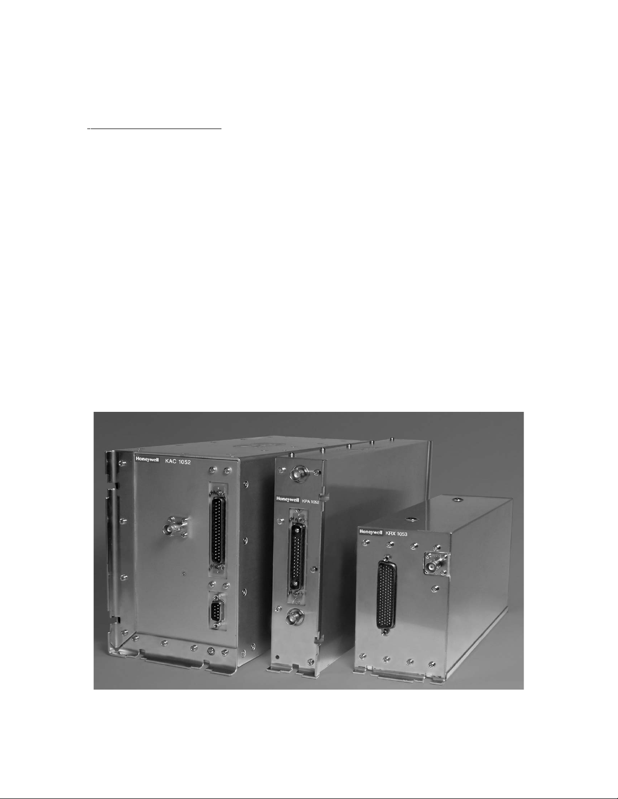
1. System Description
A basic KHF 1050 HF Communication System consists of three
individual units: KAC 1052 Antenna Coupler, KPA 1052 Power
Amplifier, and KRX 1053 Receiver/Exciter. A compatible control
unit is also required. Control units compatible with the system
include the Gables PS440, Honeywell MCDU Multifunction Control
and Display Unit and Honeywell RM-855 Radio Management Unit.
NOTE: For complete installation information on the Gables
PS440 refer to the PS440 Control Display Unit
Installation Manual P/N 006-10655-0000.
For complete installation information on the MCDU
Multfuntion Control and Display Unit refer to the MCDU
Installation Manual P/N XXXX.
For complete installation information on the RM-855
Radio Management Unit refer to the RM-855 Installation
Manual P/N XXXX.
Typical System
Figure 1
Revision 0 Page 1
10640I00.SLK Mar/2003
23-10-09
Page 19
N
Preliminary - Subject to Change Without Notice
KHF 1050 SYSTEM INSTALLATION MANUAL
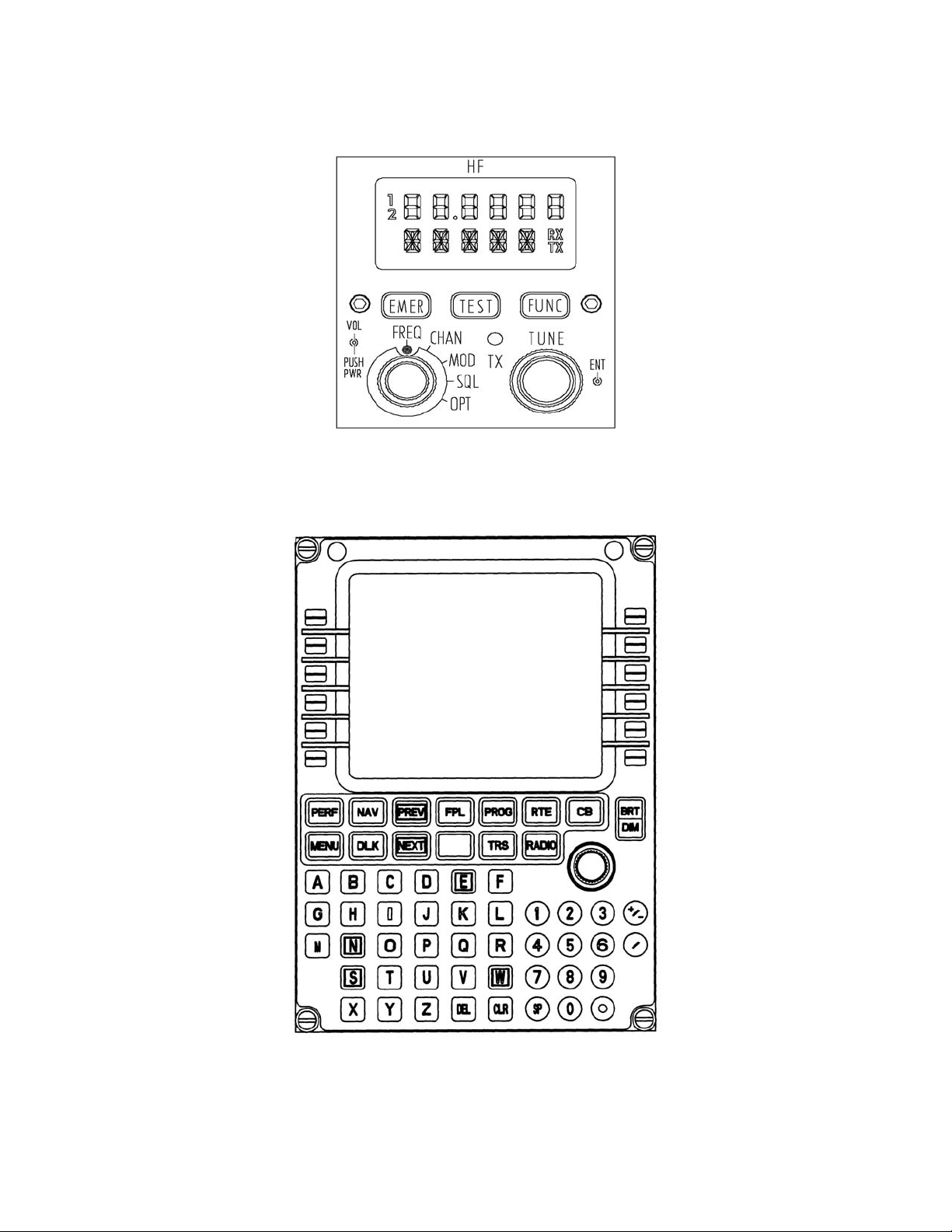
PS440 Control Display Unit
Figure 2
MCDU Multfunction Control and Display Unit
Figure 3
Revision 0 Page 2
10640I00.SLK Mar/2003
23-10-09
Page 20
N
Preliminary - Subject to Change Without Notice
KHF 1050 SYSTEM INSTALLATION MANUAL
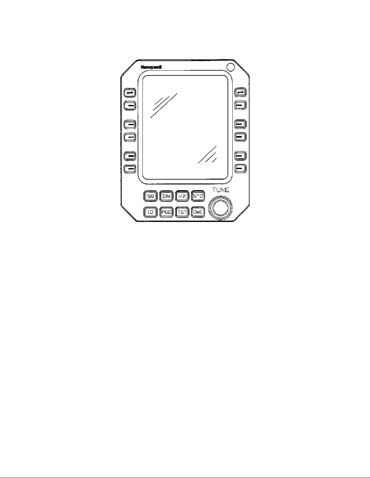
RM-855 Radio Management Unit
1.A. System Overview
The KHF 1050 HF voice and data communication system is a solid
state design with 200 watts (PEP) of output power, operating
at 28 Vdc. Frequency of operaton ranges between 2.0 and
29.9999 MHz with 100 Hz resolution. Systems may be strapped
to set the upper frequency limit to 22.9999 MHz.
NOTE: Operations are limited to 25 MHz for aircraft
installation by aeronautical mobile band frequency
limits.
A configuration is called a “dual system” when two KHF 1050
HF systems are installed in the same aircraft to share one
antenna. Both systems may receive simultaneously, but only one
system is chosen to transmit at any one time. An auto select
transmit scheme determines which system is selected to
transmit.
Figure 4
Revision 0 Page 3
10640I00.SLK Mar/2003
23-10-09
Page 21

N
Preliminary - Subject to Change Without Notice
KHF 1050 SYSTEM INSTALLATION MANUAL
In an auto select configuration, the first system (System 1
or System 2) to be keyed is selected to transmit, and
transmission from the other system is inhibited until the
first system has stopped transmitting.
The RM-855 Radio Management Unit, the MDCU Multifunction
Control Display Unit, or the PS440 Stand-Alone HF Controller
determines the frequency and mode of operation of the system
and displays that information to the pilot.
Receiver and low level transmitter signals are located in the
KRX 1053 Receiver/Exciter. The KRX 1053 Receiver/Exciter
employs an oven controlled oscillator, which requires a short
warm-up period to generate the frequency reference required
for the synthesizer.
The KAC 1052 Power Amplifier amplifies the excitation signal
from the KRX 1053 Receiver/Exciter to 200 watts PEP, or 50
watts of carrier power in AM. The amplified signal is routed
to the KAC 1052 Antenna Coupler, which matches the various
impedances of the antenna to the 50 ohm output of the
transmitter. In receive function, signals from the antenna
pass through the KAC 1052 Antenna Coupler to the KRX 1053
Receiver/Exciter.
The KHF 1050 can be installed as a single or dual HF system.
In a dual system when one system is transmitting, receive on
the other system is disbled. The single antenna in a dual
system can be tuned to only one frequency at any given time.
If the two systems are tuned to different frequencies, the
strongest reception is realized on the primary system, which
is tuned to the same frequency as the antenna. The primary
system is defined as the system that was last used for
transmission in auto-select configuration. The secondary
system would employ an internal bridging amplifier to improve
reception. No external accessories ae required for dual system
operation for the KHF 1050.
When two independent HF systems employing two separate
antennas are used on one aircraft, it is important to maximize
separation between the antennas. A minimum of 6 ft. (2 m.)
separation is recommended and the antennas should be
configured as orthogonally as possible.
Revision 0 Page 4
10640I00.SLK Mar/2003
23-10-09
Page 22

N
Preliminary - Subject to Change Without Notice
KHF 1050 SYSTEM INSTALLATION MANUAL
WARNING: IN A DUAL KHF 1050 INSTALLATION, PERMANENT DAMAGE
WILL OCCUR TO THE SYSTEM IF EITHER THE RF OR DC
CABLES ARE NOT CONNECTED PROPERLY BETWEEN HF1 AND
HF2. IT IS RECOMMENDED THAT HF1 CABLES BE COLOR
CODED RED AND HF2 CABLES BE COLOR CODED GREEN.
Several operating mode options are available for the KHF 1050
HF system to meet particular operational needs.
USB (upper sideband A3J) AME (amplitude modulation equivalent
A3H) are standard modes of operation permitted on all system
configurations.
LSB (lower sideband A3J) operation is not permitted for
stations operating under Part 87 FCC (USA) regulations. LSB
may be enabled for use in regions or applications where its
use is authorized.
A seldom used mode A3A (USB reduced carrier) if available for
use in locations that may utilize the mode.
Table 23, Modes of Operation, lists the modes of operation
applicable to the PS440, MCDU, and RM-855 controllers.
The system is capable of operating in a channel (frequency
preset) mode or a direct frequency mode. A microcomputer
within the system provides the following functions:
• controls the non-volatile storage of frequency, mode and
channel data
• controls a multiplexed eight-digit frequency display
• provides synthesizer serial data tuning information
• provides tune and transmit mode control logic
• provides band switching information
• preset antenna tune
• built-in test with fault display
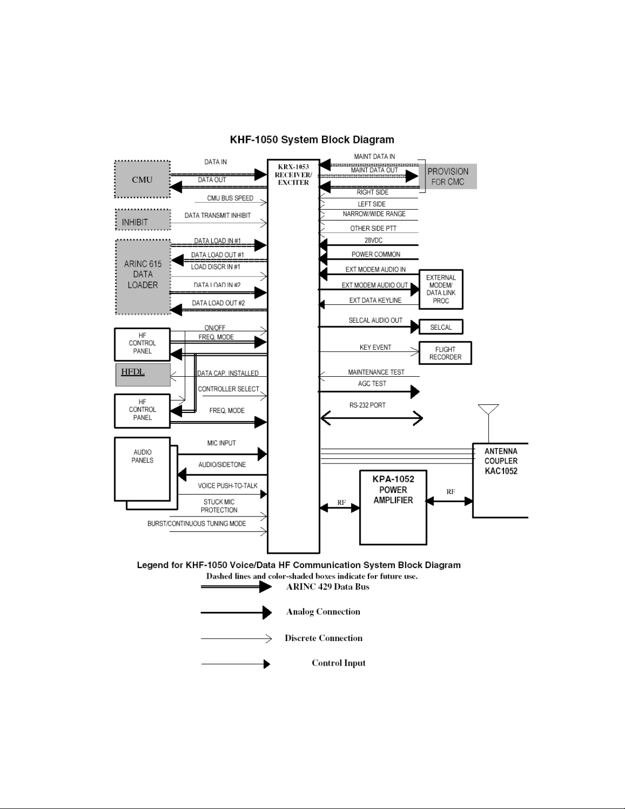
Dashed lines and shaded boxes in the block diagram, Figure 5,
indicate for future use.
Revision 0 Page 5
10640I00.SLK Mar/2003
23-10-09
Page 23
N
Preliminary - Subject to Change Without Notice
KHF 1050 SYSTEM INSTALLATION MANUAL
Typical System Block Diagram
Figure 5
Revision 0 Page 6
10640I00.SLK Mar/2003
23-10-09
Page 24

N
Preliminary - Subject to Change Without Notice
KHF 1050 SYSTEM INSTALLATION MANUAL
This version of the block diagram does not attempt to show
the interconnectins between the receiver/exciter, the power
amplifier, and the antenna coupler.
This version of the block diagram corresponds to the content
of Technical Specification Rev C, January, 2002.
1.B. System Component Descriptions
The required and optional equipment of a KHF 1050 HF
Communication System is listed below:
• KAC 1052 Antenna Coupler (required)
• KPA 1052 Power Amplifier (required)
• KRX 1053 Receiver/Exciter (required)
• Compatible HF Control Display Unit (required)
• Mounting Tray Hardware (optional)
1.B.(1) KAC 1052 Antenna Coupler
(P/N 064-01074-0001)
Under microprocessor control, the KAC 1052 antenna coupler
selects tuning network configurations, impedance
transformations and binary capacitance and inductance to
produce a VSWR of 2.5:1 or less upon initial tune. The
VSWR may then deteriorate to 3:1 before the coupler will
retune when transmit is next initiated.
1.B.(2) KPA 1052 Power Amplifier
(P/N 064-01072-0101)
The KPA 1052 is a high frequency power amplifier. From 2.0
to 29.999MHz, the power amplifier is capable of linear
amplification of a 0dBm signal to a 200 Watt output level
at 50 ohms input and output impedance.
1.B.(3) KRX 1053 Receiver/Exciter
(P/N 064-01073-0101)
The KRX 1053 is a high frequency receiver/exciter that is
designed to operate from 2.0 to 29.999MHz synthesized in
100Hz steps. The unit will operate Amplitude Modulation
Equivalent, Upper and Lower Sideband modes and
Required-Carrier mode.
Revision 0 Page 7
10640I00.SLK Mar/2003
23-10-09
Page 25

N
Preliminary - Subject to Change Without Notice
KHF 1050 SYSTEM INSTALLATION MANUAL
1.B.(4) Gables PS440 Control Display Unit
(P/N 071-01605-0101, -0201, -1101, -1201, -2101)
The PS440 stand-alone HF COMM Control Panel is designed
to provide control of a single or dual HF COMM radio
system. Full operational control of the HF system is
accomplished via a dedicated low speed, digital ARINC 429
bus.
1.B.(5) MCDU Multfunction Control and Display Unit
(P/N 7025725-901, -910, -920, -930, -940)
This multi-function radio controller provides control of
all the functions of the KHF 1050 system via ARINC 429.
Frequency, channel, squelch type and level, emission type
and power level are selected from the MCDU.
1.B.(6) RM-855 Radio Management Unit
(P/N 7013270-967/968)
The RM-855 displays frequency, mode and maintenance
information. Via the ARINC 429 bus it provides frequency,
channel, transmitter power and squelch level selection.
It also has fault monitoring and fault annunciation.
1.C. Component Installation Kits
COMMENTARY: THE FOLLOWING INSTALLATION KIT INFORMATION IS
PRELIMINARY, PENDING CHANGE ORDER RELEASE.
1.C.(1) KAC 1052 Antenna Coupler Installation Kits
Part Number Description UM Qty
030-00005-0000 CONN BNC UG 99C/U EA 1
030-01157-0011 SOCKET CRMP 20G EA 37
030-03517-0004 CONN, D-SUB, RECPT, CRMP, HOOD, 37 POS EA 1
047-06261-0036 GROUND STRAP EA 1
057-05944-0027 VERT TSO KIT LABEL, KAC 1052 EA 1
071-00200-0000 VERT TRAY ASSEMBLY KAC 1052 EA 1
KAC 1052 Single Vertical Installation Kit
(P/N:050-03658-0000)
Table 1
Revision 0 Page 8
10640I00.SLK Mar/2003
23-10-09
Page 26

N
Preliminary - Subject to Change Without Notice
KHF 1050 SYSTEM INSTALLATION MANUAL
Part Number Description UM Qty
057-05944-0034 VERT TSO KIT LABEL, KAC 1052 EA 1
071-00200-0000 VERT TRAY ASSEMBLY, KAC 1052 EA 1
KAC 1052 Single Vertical Installation Kit (tray only)
(P/N:050-03658-0001)
Table 2
Part Number Description UM Qty
030-00005-0000 CONN BNC UG 88C/U EA 1
030-01157-0011 SOCKET CRMP 20G EA 37
030-03517-0004 CONN, D-SUB, RECPT, CRMP, HOOD,37 POS EA 1
057-05944-0036 TSO KIT LABEL EA 1
KAC 1052 Single Vertical Install Kit (connectors only)
(P/N:050-03658-0002)
Table 3
Part Number Description UM Qty
030-00005-0000 CONN BNC UG 88C/U EA 1
030-01157-0011 SOCKET CRMP 20G EA 37
030-03517-0004 CONN, D-SUB, RECPT, CRMP, HOOD,37 POS EA 1
047-06261-0036 GROUND STRAP EA 1
047-12728-0001 KAC 1052 GROUND STRAP EA 1
057-05944-0029 HORIZ TSO KIT LABEL, KAC 1052 EA 1
071-00202-0000 HORIZ TRAY ASSEMBLY, KAC 1052 EA 1
155-02988-0015 HN CABLE EA 1
KAC 1052 Single Horizontal Installation Kit
(P/N:050-03660-0000)
Table 4
Revision 0 Page 9
10640I00.SLK Mar/2003
23-10-09
Page 27

N
Preliminary - Subject to Change Without Notice
KHF 1050 SYSTEM INSTALLATION MANUAL
Part Number Description UM Qty
030-00005-0000 CONN BNC UG 88C/U EA 2
030-01157-0011 SOCKET CRMP 20G EA 74
030-03517-0004 CONN, D-SUB, RECPT, CRMP, HOOD, 37 POS EA 2
047-06261-0036 GROUND STRAP EA 2
057-05944-0030 DUAL VERT KAC 1052 TSO KIT LABEL EA 1
071-00200-0000 VERT TRAY ASSEMBLY KAC 1052 EA 2
KAC 1052 Dual Vertical Installation Kit
(P/N:050-03661-0000)
Table 5
Part Number Description UM Qty
057-05944-0035 DUAL VERT TSO KIT LABEL, KAC 1052 EA 1
071-00200-0000 VERT TRAY ASSEMBLY, KAC 1052 EA 2
KAC 1052 Dual Vertical Installation Kit (tray only)
(P/N:050-03661-0001)
Table 6
Part Number Description UM Qty
030-00005-0000 CONN BNC UG 88C/U EA 2
030-01157-0011 SOCKET CRMP 20G EA 74
030-03517-0004 CONN, D-SUB, RECPT, CRMP, HOOD,37 POS EA 2
057-05944-0039 TSO KIT LABEL EA 1
KAC 1052 Dual Vertical Installation Kit (connectors only)
(P/N:050-03661-0002)
Table 7
Revision 0 Page 10
10640I00.SLK Mar/2003
23-10-09
Page 28

N
Preliminary - Subject to Change Without Notice
KHF 1050 SYSTEM INSTALLATION MANUAL
1.C.(2) KPA 1052 Power Amplifier Installation Kits
Part Number Description UM Qty
030-00005-0000 CONN BNC UG 88C/U EA 2
030-01157-0011 SOCKET CRMP 20G EA 25
030-01466-0002 CONN, D-SUB, CONTACT, CRMP, PWR, SIZE 8 EA 2
030-03516-0001 CONN, D-SUB, RECPT, COMBO-27W2, CRMP EA 1
057-05944-0022 TSO KIT LABEL EA 1
071-00185-0000 TRAY ASSEMBLY EA 1
KPA 1052 Single Horizontal Installation Kit
(P/N:050-03629-0000)
Table 8
Part Number Description UM Qty
057-05944-0033 KSO KIT LABEL, KPA 1052 EA 1
071-00185-0000 TRAY ASSEMBLY EA 1
KPA 1052 Installation Kit (tray only)
(P/N:050-03629-0001)
Table 9
Part Number Description UM Qty
030-00005-0000 CONN BNC UG88C/U EA 2
030-01157-0011 SOCKET CRMP 20G EA 25
030-01466-0002 CONN, D-SUB, ACCESSORY, CONTACT, CRMP,
PWR
030-03516-0001 CONN, D-SUB, RECPT, COMBO - 27W2,
CRIMP, HOOD, V-LOC
057-05944-0037 TSO KIT LABEL EA 1
EA 2
EA 1
KPA 1052 Installation Kit (connectors only)
(P/N:050-03629-0002)
Table 10
Revision 0 Page 11
10640I00.SLK Mar/2003
23-10-09
Page 29

N
Preliminary - Subject to Change Without Notice
KHF 1050 SYSTEM INSTALLATION MANUAL
1.C.(3) KRX 1053 Receiver/Exciter Installation Kits
Part Number Description UM Qty
030-00005-0000 CONN BNC UG 88C/U EA 1
030-01451-0000 CONTACT SOCKET EA 104
030-03518-0001 CONN, D-SUB, RECPT, HI-DENS, W/HOOD,
104 POS
057-05944-0021 TSO KIT LABEL EA 1
071-00184-0000 TRAY ASSEMBLY EA 1
KRX 1053 Installation Kit
(P/N 050-03628-0000)
Table 11
Part Number Description UM Qty
057-05944-0032 TSO KIT LABEL EA 1
071-00184-0000 TRAY ASSEMBLY EA 1
KRX 1053 Installation Kit (tray only)
P/N 050-03628-0001
Table 12
EA 1
Part Number Description UM Qty
030-00005-0000 CONN BNC UG88C/U EA 1
030-01466-0001 CONN D-SUB,ACCESSORY, CONTACT 22AWG,
CRMP, FEMALE
030-03518-0001 CON, D-SUB, ACCESSORY, HOOD, 104 POS EA 1
057-05944-0038 TSO KIT LABEL EA 1
KRX 1053 Installation Kit (connectors only)
P/N 050-03628-0002
Table 13
Revision 0 Page 12
10640I00.SLK Mar/2003
23-10-09
EA 104
Page 30

N
Preliminary - Subject to Change Without Notice
KHF 1050 SYSTEM INSTALLATION MANUAL
Part Number Description UM Qty
3280 VERTICAL FIN ANCHOR KIT EA 1
5 ARM 200-6LV VERTICAL FIN “V” TENSION KIT EA 1
50 ARM 300-205 ANTI-PRECIPITATION ANTENNA WIRE FT 45
25 ARM 300-20E 30° FEED-THROUGH INSULATOR EA 1
50 ARM 300-250 WIRE RELEASE TOOL EA 1
FORM #101 INSTALLATION INSTRUCTIONS EA 1
16390 FEED-THROUGH ASSEMBLY EA 1
Long-Wire Antenna Installation Kit
(P/N:071-01214-0001)
Table 14
1.D. Equipment Required But Not Supplied
Equipment Required But Not Supplied
AIRCRAFT EQUIPMENT DESCRIPTION
Power 28 Vdc Primary power source.
Lighting Bus 5 Vac, 5
Vdc or 28 Vdc
Microphone Noise cancelling, 150 ohms nominal,
Headphones Approx. 600 ohms.
Selective Calling
Decoder
Ground Strap 047-06261-0036 36” length
Panel lighting power source for control
units, according to version installed.
pre-amplified.
AVTGA
Required if SELCAL operation is
desired.
Long Wire HF Antenna Long Wire HF Antenna Kit available as
P/N 071-01214-0000.
Revision 0 Page 13
10640I00.SLK Mar/2003
23-10-09
Page 31

N
Preliminary - Subject to Change Without Notice
KHF 1050 SYSTEM INSTALLATION MANUAL
Equipment Required But Not Supplied
AIRCRAFT EQUIPMENT DESCRIPTION
Grounded Tranline Grounded tranline: Towel bar with 1
inch diameter recommended. Contact:
Trivec-Avant Corp.
17831 Jamestown Ln.
Huntington Beach, CA 92647
714-841-4976
WIRE: Available as:
RG 400 Double shielded coax P/N 024-00075-0000
RG 142B/U Double shielded coax P/N 024-00002-0000
24 AWG Single conductor P/N 025-00029-0009
20 AWG Single conductor P/N 025-00031-0000
16 AWG Single conductor P/N 025-00031-0003
24 AWG Single conductor with shield and jacket
P/N 025-05018-0000
18 AWG Single conductor with shield and jacket
P/N 025-05019-0000
24 AWG Two conductor with shield and jacket
P/N 025-05020-0000
24 AWG Three conductor with shield and jacket
P/N 025-05023-0000
CABLE:
AN-22a 755 Nominal Circular Mil Area*
0.090 inches Max. Overall Diameter
16.45 ohms Max. per 1000 feet @ 20°C
8 amps Max. Cont. Current Rating**
5 amps Max. Cont. Current Rating***
AN-20 1,200 Nominal Circular Mil Area*
0.100 inches Max. Overall Diameter
10.25 ohms Max. per 1000 feet @ 20°C
11 amps Max. Cont. Current Rating**
7.5 amps Max. Cont. Current Rating***
Revision 0 Page 14
10640I00.SLK Mar/2003
23-10-09
Page 32

N
Preliminary - Subject to Change Without Notice
KHF 1050 SYSTEM INSTALLATION MANUAL
Equipment Required But Not Supplied
AIRCRAFT EQUIPMENT DESCRIPTION
AN-18 1,909 Nominal Circular Mil Area*
0.115 inches Max. Overall Diameter
6.44 ohms Max. per 1000 feet @ 20°C
16 amps Max. Cont. Current Rating**
10 amps Max. Cont. Current Rating***
AN-16 2,409 Nominal Circular Mil Area
0.130 inches Max. Overall Diameter
4.76 ohms Max. per 1000 feet @ 20°C
22 amps Max. Cont. Current Rating**
13 amps Max. Cont. Current Rating***
AN-14 3,830 Nominal Circular Mil Area
0.150 inches Max. Overall Diameter
2.99 ohms Max. per 1000 feet @ 20°C
32 amps Max. Cont. Current Rating**
17 amps Max. Cont. Current Rating***
AN-12 6,088 Nominal Circular Mil Area
0.170 inches Max. Overall Diameter
1.88 ohms Max. per 1000 feet @ 20°C
41 amps Max. Cont. Current Rating**
23 amps Max. Cont. Current Rating***
High Voltage HN Cables:
155-02988-2215 Designed for single 1050 installation.
Length is 15” 38.1 cm). Both connectors
are straight.
155-02989-0001 Designed for dual 1050 installation.
Total length is 16” (40.64 cm). Common
leg is 6” (15.24 cm). Each separate leg
is 10” (25.4 cm). All three connectors
are straight.
155-02988-0121 Designed for single 1050 installaton.
21” (53.34 cm) length center, both
connectors right angle, 180 degree
indexing (one connector up, one down).
Revision 0 Page 15
10640I00.SLK Mar/2003
23-10-09
Page 33

N
Preliminary - Subject to Change Without Notice
KHF 1050 SYSTEM INSTALLATION MANUAL
Equipment Required But Not Supplied
AIRCRAFT EQUIPMENT DESCRIPTION
155-02988-0015 Designed for single 1050 installation.
Length is 15” (38.1 cm). Both
connectors are right angle with the
same orientation.
Miscellaneous installation hardware
mounting brackets
wire
cables
nuts
bolts
Equipment Required But Not Supplied
Table 15
WARNING: THE HIGH VOLTAGE HN CABLES ARE SPECIFICALLY DESIGNED TO
WITHSTAND THE HIGH VOLTAGE GENERATED BY THE KHF 1050
SYSTEM. THEY CAN NOT BE REPLACED BY CABLES THAT HAVE NOT
BEEN TESTED TO THESE HIGH VOLTAGES AT ALTITUDE. THESE
CABLES SHOULD BE PURCHASED DIRECTLY FROM HONEYWELL, OR
FROM THE QUALIFIED VENDOR (CANTON CONNECTOR CORP, 26
WAPPING ROAD, KINGSTON, MA, 02364, 781-585-4315).
1.E. Related Publications
Part Number Description
006-15640-0000 KAC 1052 Antenna Coupler Maintenance Manual
006-15641-0000 KPA 1052 Power Amplifier Maintenance Manual
006-15642-0000 KRX 1053 Receiver/Exciter Maintenance Manual
006-15655-0000 PS440 Control Display Unit Maintenance Manual
A09-3642 MCDU Multfunction Control and Display Unit
Mainenance Manual
???? RM-855 Radio Management Unit Maintenance Manual
Related Publications
Table 16
Revision 0 Page 16
10640I00.SLK Mar/2003
23-10-09
Page 34

N
Preliminary - Subject to Change Without Notice
KHF 1050 SYSTEM INSTALLATION MANUAL
NOTE: An Aircraft Station License is required for KHF 1050
HF system equipment. Forms (FCC Form 404, New Aircraft
Station License, or FCC 405A, Renewal of Aircraft
Station License) can be obtained from the nearest FCC
Field Office.
2. Component Configurations
System component configurations are listed in this section. The
overall configuration of a KHF 1050 HF system is dependent on
the component versions installed in the aircraft.
2.A. KAC 1052 Antenna Coupler Unit Configurations
PART NUMBER VERSION DESCRIPTON
064-01074 -0101
KAC 1052 Configurations
2.B. KPA 1052 Power Amplifier Configurations
PART NUMBER VERSION DESCRIPTION
064-01072 -0101
KPA 1052 Configurations
2.C. KRX 1053 Receiver/Exciter Configurations
PART NUMBER VERSION DESCRIPTION
064-01073 -0101
Antenna Coupler - standard
Table 17
Power Amplifier - standard
Table 18
Receiver/Exciter - standard
KRX 1053 Configurations
Table 19
Revision 0 Page 17
10640I00.SLK Mar/2003
23-10-09
Page 35

N
Preliminary - Subject to Change Without Notice
KHF 1050 SYSTEM INSTALLATION MANUAL
2.D. PS440 Control Display Unit Configurations
PART NUMBER VERSION BEZEL LCD BACKLIGHTING
071-01605 -0101 Gray White
071-01605 -0201 Black White
071-01605 -1101 Gray Amber
071-01605 -1201 Black Amber
071-01605 -2101 Gray NVIS
071-01605 -2201 Black NVIS
PS440 Configurations
Table 20
2.E. MCDU Multfunction Control and Display Unit Configurations
PART NUMBER VERSION USER
7025725 -901 Hawker Horizon
7025725 -910 Planeview GV, Cessna Sovereign
7025725 -920 (no user at present)
7025725 -930 Embraer ERJ 170
7025725 -940 Agusta AB139
MCDU Configurations
Table 21
2.F. RM-855 Radio Management Unit Configurations
PART NUMBER VERSION FEATURES BEZEL
7013270 -967 Radio Management Unit - HF Gray
7013270 -968 Radio Management Unit - HF Black
RM-855 Configurations
Table 22
Revision 0 Page 18
10640I00.SLK Mar/2003
23-10-09
Page 36

KHF 1050 SYSTEM INSTALLATION MANUAL
Preliminary - Subject to Change Without Notice
3. System Leading Particulars
3.A. General Specifications
The KHF 1050 HF System is a solid state design with 200 watts
PEP of output power, supplied by 28 VDC, with an operational
frequency range of 2.0 to 29.9999 MHz with 100kHz resolution.
The KHF 1050 HF System has been type accepted by the FCC and
TSO approved.
3.B. System Operating Modes
3.B.(1) Emission Modes
Several operating mode options are available for the KHF
1050 HF system to meet particular operational needs.
USB (upper sideband, A3J) AME (amplitude modulation
equivalent A3H) are standard modes of operation permitted
on all system configurations.
N
LSB (lower sideband, A3J) operation is not permitted for
stations operating under Part 87 FCC (USA) regulations.
LSB may be enabled for use in regions or applications
where its use is authorized.
AM or AME (amplitude modulation equivalent, A3H) may be
used in some areas that lack single-sideband (SSB)
capabilities. AME is a form of amplitude modulation that
is more efficient than full AM, yet compatible with AM
systems.
USB Data and LSB Data are the same as the above-mentioned
USB and LSB modes, except receiver audio and transmitter
audio are connectedto a data-modem rather than to a
speaker or microphone.
A seldom used mode A3A (USB reduced carrier) is available
for use in locations that may utilize the mode.
Table 25, Modes of Operation, lists the modes of operation
applicable to the PS440, MCDU and RM-855.
Revision 0 Page 19
10640I00.SLK Mar/2003
23-10-09
Page 37

N
Preliminary - Subject to Change Without Notice
KHF 1050 SYSTEM INSTALLATION MANUAL
MODE OF OPERATION DESIGNATOR
TECHNICAL
OLD NEW
A3H H3E AME AM Equivalent AM AM AM
A3A R3E AM Reduced Carrier RC RC
A3J J3E USB Upper Sideband UV UV UV
A3J J3E LSB Lower Sideband LV LV LV
A7J J2D USB Data Upper Sideband Data UD UD UD
A7J J2D LSB Data Lower Sideband Data LD LD LD
H2D AM Data Amplitude Modulation Data AM AM AM
3.B.(2) 23 MHz Limit Mode
ALTERNATE PS440 MCDU RM-855
Modes of Operation
Table 23
CONTROL UNIT
DESIGNATOR
The KHF 1050 HF system can be strapped to limit the
frequency of operation to an upper limit of 22.9999 MHz
for certification in countries that may require such an
upper frequency limit.
3.B.(3) Channel Mode
When operating in the channel mode the KHF 1050 HF system
can operate as a simplex, semi-simplex, or receive only
communication system. Transmit and receive frequencies
are selected by selecting a pre-programmed channel.
3.B.(4) Direct Frequency Mode
When operating in the direct frequency mode the KHF 1050
HF system can operate as a simple communication system
only. Transmit and receive frequency is determined by the
selected frequency, which is entered directly on the
control unit.
Revision 0 Page 20
10640I00.SLK Mar/2003
23-10-09
Page 38

KHF 1050 SYSTEM INSTALLATION MANUAL
Preliminary - Subject to Change Without Notice
3.B.(5) Data Mode
When the KRX 1053 Receiver/Exciter is operating in the
DATA mode, interface with data modems or secure voice
systems is enabled. The external modem inputs and external
modem outputs are available to bypass squelch and
compression functions in the KRX 1053. These levels are
controlled by field adjustments.
A 4 dB variation is possible in the audio response when
operating in the data mode.
Audio modulation from the modem is applied to the EXTERNAL
MODEM AUDIO INPUT. When the DATA KEYLINE is grounded, the
transmitter modulation is derived from the DATA AUDIO
INPUT rather than from the microphone.
3.B.(6) SELCAL Mode
N
NOTE:
SELCAL (SELective CALling) may be used to relieve
background noises during flight. The volume may be turned
down completely while the system maintains a watch for a
SELCAL coded audio signal.
When a decoded SELCAL signal is received, a call waiting
is indicated. The SELCAL decoder generates an audio alert
for the crew.
The SELCAL AUDIO OUTPUT is connected to the external
SELCAL decoder. Regardless of the operating mode selected
by the pilot, the SELCAL AUDIO OUTPUT is derived from an
AM receiver inside the KRX 1053.
SELCAL mode requires a SELCAL decoder, not
supplied.
Revision 0 Page 21
10640I00.SLK Mar/2003
23-10-09
Page 39

N
Preliminary - Subject to Change Without Notice
KHF 1050 SYSTEM INSTALLATION MANUAL
3.C. Component Leading Particulars
Leading particulars for components of the KHF 1050 HF system
are listed below.
3.C.(1) KAC 1052 Antenna Coupler, Leading Particulars
CHARACTERISTIC DESCRIPTION
Weight: Refer to Figure 2028 (P/N 155-01774-2028)
Dimensions: Refer to Figure2028 (P/N 155-01774-2028)
Connector: Refer to figure 2009 (J10521) and table
2001.
KAC 1052 Leading Particulars
Table 24
3.C.(2) KPA 1052 Power Amplifier, Leading Particulars
CHARACTERISTIC DESCRIPTION
Weight: Refer to figure2031 (P/N 155-01450-0000)
Dimensions: Refer to figure2031 (P/N 155-01450-0000)
Connector: Refer to figure 2010 (J10524) and table
2002.
KPA 1052 Leading Particulars
Table 25
3.C.(3) KRX 1053 Receiver/Exciter, Leading Particulars
CHARACTERISTIC DESCRIPTION
Weight: Refer to Figure 2032 (P/N 155-01751-0000)
Dimensions: Refer to Figure 2032 (P/N 155-01751-0000)
Connector: Refer to figure 2011 (J10531) and table
2003.
KRX 1053 Leading Particulars
Table 26
Revision 0 Page 22
10640I00.SLK Mar/2003
23-10-09
Page 40

N
Preliminary - Subject to Change Without Notice
KHF 1050 SYSTEM INSTALLATION MANUAL
3.C.(4) PS440 Control Display Unit, Leading Particulars
NOTE: Refer to the PS440 Control Display Unit Component
Maintenance Manual P/N 006-15655-XXXX for more
description of the PS440.
CHARACTERISTIC DESCRIPTION
Weight: Refer to Figure 2022 (P/N ???)
Dimensions: Refer to Figure 2022 (P/N ???)
Connector: Refer to figure 2011 (J1) and table 2004.
PS440 Leading Particulars
Table 27
3.C.(5) MCDU Multifuction Control and Display Unit, Leading
Particulars
NOTE: Refer to the MCDU Multifunction Control and Display
Unit Maintenance Manual P/N A09-3642 for more
description of the MCDU.
CHARACTERISTIC DESCRIPTION
Weight: Refer to figure 2023 (P/N 7025726-930)
Dimensions: Refer to figure 2023 (P/N 7025726-930)
Connector: Refer to figure 2016 (J???) and table
2007.
MCDU Leading Particulars
Table 28
Revision 0 Page 23
10640I00.SLK Mar/2003
23-10-09
Page 41

N
Preliminary - Subject to Change Without Notice
KHF 1050 SYSTEM INSTALLATION MANUAL
3.C.(6) RM-855 Radio Management Unit, Leading Particulars
NOTE: Refer to the RM-855 Radio Management Unit Component
Maintenance Manual P/N ??? for more description of
the RM-855.
CHARACTERISTIC DESCRIPTION
Weight: Refer to figure 2026 (P/N 7013270)
Dimensions: Refer to figure 2026 (P/N 7013270)
Connector: Refer to figure 2016 (J???) and table
2007.
RM-855 Leading Particulars
Table 29
4. System Function
4.A. System Functional Overview
The KHF 1050 HF Communication System supports a wide variety
of communication requirements. The major components of the
KHF 1050 HF system are listed below:
y KAC 1052 Antenna Coupler
y KPA 1052 Power Amplifier
y KRX 1053 Receiver/Exciter
y Compatible Control Display Unit
The basic KHF 1050 HF system is a mobile communication system
for aircraft. It operates in a frequency range between 2.0
and 29.9999 MHz offering several different emission modes to
provide voice communication.
By including the appropriate components in an installation,
the KHF 1050 HF system capabilities can be increased to allow
the system to support Data, SELCAL, and Secure Voice
communication.
4.A.(1) System Power UP
COMMENTARY: INSERT POWER-UP DESCRIPTION HERE.
Revision 0 Page 24
10640I00.SLK Mar/2003
23-10-09
Page 42

N
Preliminary - Subject to Change Without Notice
KHF 1050 SYSTEM INSTALLATION MANUAL
4.A.(2) Channel Operation
COMMENTARY: INSERT CHANNEL OPERATION DESCRIPTION HERE.
4.A.(3) Direct Frequency Mode
COMMENTARY: INSERT DIRECT FREQUENCY MODE OPERATION HERE.
4.B. Dual System
COMMENTARY: INSERT ANY DUAL SYSTEM FUNCTIONALITY INFO HERE.
5.
Component Functions
5.A. PS440 Control Display Unit Unit Function
See Pilots Guide P/N 006-18289-0000 for PS440 Control Display
Unit operation.
5.B. MCDU Multfunction Control and Display Unit Function
See Pilots Guide P/N XXXX for MCDU Multfunction Control and
Display Unit operation.
5.C. RM-855 Radio Management Unit Function
See Pilots Guide P/N XXXX for RM-855 Radio Management Unit
operation.
6. System Inputs/Outputs
6.A. Input/Output Signals
See Paragraph 5.C.(5) in the Installation and Maintenance
section of this book.
Revision 0 Page 25
10640I00.SLK Mar/2003
23-10-09
Page 43

N
Preliminary - Subject to Change Without Notice
KHF 1050 SYSTEM INSTALLATION MANUAL
TESTING AND FAULT ISOLATION
1. Fault Isolation
Fault isolation locates the source of system failure at the black
box or aircraft wiring level. Fault isolation is typically
performed on the ground in response to failures indicated during
post-installation checkout, preflight testing, or flight
operation.
Perform the System Performance Check (Paragraph 2.) and refer to
the Fault Isolation Checklist (Paragraph 3.) for fault isolation
in the KHF 1050 HF system.
2. System Performance Check
The system check detects problems in the installation that may
cause the HF system to fail, to degrade performance, or cause
damage to the HF system, such as:
y Intermittent or improperly connected cables or connectors.
y Defective units.
y Poorly regulated aircraft DC power.
y Poor grounding of KHF 1050 HF system or poor aircraft bonding.
y Audio ground loops.
y RF interference.
CAUTION
CAUTION
Perform the steps in the stated sequence.
: POWER CARTS MAY REGULATE POORLY WHEN SUBJECTED TO STRONG
RF FIELDS. IF MORE THAN 20% FLUCTUATIONS IN POWER CART
VOLTAGES ARE NOTED WHEN TRANSMITTING, DO NOT CONTINUE
TESTING WITH POWER CART.
: SOME INTERMITTENT CONDITIONS MAY CAUSE OUTPUT
TRANSISTORS TO FAIL, THEREFORE TRANSMIT ONLY AFTER
OTHER CHECKS HAVE SUCCESSFULLY COMPLETED.
Revision 0 Page 1001
10640I00.SLK Mar/2003
23-10-09
Page 44

KHF 1050 SYSTEM INSTALLATION MANUAL
Preliminary - Subject to Change Without Notice
2.A. Preliminary Check
1. Prior to turning the system on, ensure that all connectors
are properly seated in their proper location.
2. Turn the system on. As the system turns on it performs a
brief self-test.
Normally, after a few seconds, the HF controller (or HF
window of a multi-function controller) will show an HF
operating frequency, mode of operation and other operating
parameters. Refer to the operating manual for the specific
controller for specific operation and the information
available on the display.
3. Push the TEST button on the controller to perform a system
test. The pilot-activated self-test takes approximately
15 seconds to complete.
N
4. KXR 1053 Receiver/Exciter Built-In-Test
The receiver/exciter design incorporates provisions for
monitoring its own operation to detect any condition or
occurrence that the operator (a flight crew member) might
observe and interpret as a reason for requesting a
maintenance action.
These maintenance observations are stored in non-volatile
memory within the receiver/exciter so they can be
retrieved with appropriate test equipment.
If a sufficiently serious fault is detected, the
“receiver/exciter status” bit of the Maintenance Status
message, label 351, is set to indicate a fault.
The maintenance data collection provision includes the
following three types of monitoring: Power-On, Continuous
Monitoring and Initiated Tests. The BITE tests that shall
be performed at system turn-on, at pilot activated, or
continuously are summarized in Table 1001. The table shows
which tests are performed for each of the three types of
monitoring.
Revision 0 Page 1002
10640I00.SLK Mar/2003
23-10-09
Page 45

N
Preliminary - Subject to Change Without Notice
KHF 1050 SYSTEM INSTALLATION MANUAL
FUNCTION TURN ON PILOT CONT Label 351
Discrete Line Check X 29
Flash ROM Checksum X 29
DSP ROM X X 29
DSP RAM X X 29
DSP CLOCK (60MHz) X X 29
RF Board XMT Operation X X 29
RF Board RCV Operation X X 29
RF Board DSP Clock (60MHz) X X 29
15V Power Line X X 29
9V Power Line X X 29
3.3V Power Line X X 29
PRIMARY Power Fail
(28V Power Line Voltage)
Rx/Ex Internal Temperature X 29
PA OK/NG X X X 18
ACP OK/NG X X X 28
Rx/Ex - CPLR Serial Communication X X 29
ACP WARN X 15
ACP Tune Fail X 28 Note 1
RX/EX BITE Matrix
Table 1001
XXX29
Revision 0 Page 1003
10640I00.SLK Mar/2003
23-10-09
Page 46

N
Preliminary - Subject to Change Without Notice
KHF 1050 SYSTEM INSTALLATION MANUAL
5. KPA 1052 Power Amplifier Built-In-Test
The power amplifier design incorporates provisions for
monitoring its own operation to detect any condition or
occurrence that the operator (a flight crew member) might
observe and interpret as a reason for requesting a
maintenance action.
The maintenance data collection provision includes the
following three types of monitoring: Power-On Test,
Conditions Monitoring and Initiated test, as defined
below.
PA Alarm 1 - This alarm will be generated whenever the SWR
at the input to the antenna coupler is too high. The
antenna coupler will try to retune to lower SWR during
transmit mode.
PA Alarm 2 - This alarm will be generated whenever an
invalid band error request occurs, a higher than normal
SWR within the PA is generated, a higher than normal
output power occurs, an over-temperature condition
exists, or the PA has no output power. This alarm inhibits
all transmissions.
The BITE tests that shall be performed at system turn-on,
at pilot activated or continuously are summarized in Table
1002.
Label 351
FUNCTION POWER ON PILOT CONT
Load SWR (PA ALM#1) During Tx Only X 18
Temperature (PA ALM#2) X 18
Transmitter Power at 50 W
(With KAC 1052 in the system)
Note1: PA ALM#1 and PA ALM#2 are sent to the KAC 1052 with
discrete lines. The KAC 1052 then sends the PA Alarm data to the
KRX 1053. Label 351 information is actually sent by the KRX 1053.
PA BITE Matrix
Table 1002
XX 18
Bit
Note 1
Revision 0 Page 1004
10640I00.SLK Mar/2003
23-10-09
Page 47

N
Preliminary - Subject to Change Without Notice
KHF 1050 SYSTEM INSTALLATION MANUAL
6. KAC 1052 Antenna Coupler Built-In-Test
The antenna coupler design incorporates provisions for
monitoring its own operation to detect any condition or
occurrence that the operator (a flight crew member) might
observe and interpret as a reason for requesting a
maintenance action.
These maintenance observations are stored in non-volatile
memory within the antenna coupler so they can be retrieved
with appropriate test equipment.
If the maintenance observation is serious enough to
indicate Antenna Coupler failure, the failure shall be
communicated to the receiver/exciter for reporting to the
HF controller.
The BITE tests that shall be performed at system turn-on,
at pilot activation or continuously are summarized in
Table 1003.
POWER
FUNCTION
Internal memory X 28
12V Power Line 28
5V Power Line X 28
Bridge amplifier output voltage X 28
Low pressure alarm signal (PRESS ALM) X X 15
Leak pressure warning level
(Temp, Press)
RF power level and Power Sensor X 28
PA alarm #1 signal (PA ALM#1)
During Tx Only
ON PILOT CONT
X X 15 & 28
XX 18
Label
351 Bit
Note 1
PA alarm #2 signal (PA ALM#2) X X 18
VSWR sensor X 28
Revision 0 Page 1005
10640I00.SLK Mar/2003
23-10-09
Page 48

N
Preliminary - Subject to Change Without Notice
KHF 1050 SYSTEM INSTALLATION MANUAL
Impedance sensors X 28
Note 1: The Label 351 information is actually sent by the KRX
1053 in response to RS-422 serial data sent by the KAC 1052 to
the KRX 1053.
Antenna Coupler BITE Matrix
TablE 1003
7. In the event that a problem is detected during either the
turn-on test or the pilot-activated self-test, an error
message will appear on the controller. The error message
may indicate a failure of one or more of the following:
• Controller
• Receiver/Exciter
• Power Amplifier
• Antenna Coupler
Refer to Section 3, Fault Isolation Checklist.
2.B. Receiver Performance Check
1. If an operating frequency is properly displayed on the
controller, listen to the speaker or headphones. Ensure
that the aircraft audio panel is properly set to select
the HP audio.
2. Select the USB Voice (UV) mode, SBH type squelch. (SBH is
the default squelch type. If using an RM855, only the SB
type is available.) Adjust the squelch level to OFF.
Adjust the volume control on the PS440 controller, and/or
the volume control on the audio panel. Depending on the
frequency or channel selected, a signal may be heard - or
perhaps just atmospheric static.
NOTE: If the aircraft is located in a metal hangar, both
signals and noise may be weak. It is advisable to
have the aircraft outside the hangar to perform the
receiver or transmitter tests.
Select a channel with a known usable signal. One
possibility is one of the time-and-frequency standard
stations operating on frequencies of 2500.0 MHz, 5000.0
MHz, 10000.0 kHz, 15000.0 kHz or 20000.0 kHz.
Revision 0 Page 1006
10640I00.SLK Mar/2003
23-10-09
Page 49

N
Preliminary - Subject to Change Without Notice
KHF 1050 SYSTEM INSTALLATION MANUAL
These stations are located in Fort Collins, Colorado and
Kekaha, Hawaii. Consult the HF frequency propagation chart
in Table 2001 for an overview of the frequency to use for
a particular time of day and distance from the
transmitter. These stations transmit in the AM mode.
However, they can be received by the KHF 1050 System in
the USB Voice (UV), LSB Voice (LV), AM or Reduce-Carrier
(RC) modes.
If a signal can not be heard,check the connetion to the
antenna, the antenna itself and ensure that all coaxial
cables that interconnect the KHF 1050 System are properly
connected.
4. Adjust the squelch level as needed to LOW, MED or MAX to
achieve the minimum level required to suppress the
receiver noise with no signal present.
2.C. Transmitter Performance Check
1. Select the HF positon on the audio panel microphone
switch.
CAUTION: VERIFY THAT NO ONE IS STANDING ON THE GROUND NEAR
THE AIRCRAFT OR TOUCHING THE AIRCRAFT. WITH MANY
TYPES OF AIRCRAFT HF ANTENNAS, THE ENTIRE
AIRFRAME BECOMES PART OF THE ANTENNA. ANYONE
STANDING ON THE GROUND COULD RECEIVE AN
ELECTRICAL SHOCK IF TOUCHING THE AIRCRAFT, OR IF
ENTERING OR EXITING THE AIRCRAFT DURING A
TRANSMISSION BY THE KHF 1050 SYSTEM. DO NOT
OPERATE THE HF SYSTEM WHILE THE AIRCRAFT IS BEING
FUELED.
2. Select a channel on which the aircraft is authorized to
transmit, with the apropriate mode of operation, which is
typically USB Voice (UV). Momentarily press the PTT switch
to start the antenna tuing process.
Assuming the KAC 1052 Antenna Coupler has not previously
been on this frequency, the antenna coupler will begin to
tune to the antenna and the controller display will begin
to indicate that tuning is taking place. Refer to the
controller information for the details of how tuning is
annunciated by the particular controller being used.
Revision 0 Page 1007
10640I00.SLK Mar/2003
23-10-09
Page 50

N
Preliminary - Subject to Change Without Notice
KHF 1050 SYSTEM INSTALLATION MANUAL
In the event that the operating frequency selected had
previously been tuned by the KAC 1052 Antenna Coupler, the
antenna coupler will utilize stored tune information and
match to the antenna in less than 50msec. However, changes
in antenna impedance can occasionally result in the KAC
1052 needing to retune on a previously tuned frequency.
3. Upon completion of the tune cycle, the tune indication
will disappear and the display will return to a normal
recieve window. The receiver audio will likely be stronger
than it was prior to tuning the antenna and it may be
necessary to readjust the squelch if there is significant
noise on the channel. The system is now ready to transmit
voice communications.
4. In order to ensure good audio quality of the transmitted
signal, a microphone-ground-loop test is recommended. To
check for microphone ground loops, select the AM mode on
an unused frequency. Key the system with no modulation,
preferably covering the microphone element with your hand.
Listen for any squeal or popping sound in the speaker or
headphones. A squeal or popping sound tends to indicate
that a microphone ground loop exists. Microphone ground
loops will result in distorted audio. Such a ground loop
is usually the result of the microphone audio low line
being tied to airframe ground at multiple points.
5. Listen to the sidetone in the headphones or speaker while
transmitting, both in USB Voice (UV) and in AM. A raspy
sound may indicate that RF interference is feeding back
into the HF or audio system.
6. While transmitting a voice test message in USB Voice (UV),
observe other electrical equipment in the aircraft and
note any interference observed that correlates to the HF
transmission.
7. Voice communications should be established with a ground
station or another aircraft. See Section 7.B.(4)(b).
Revision 0 Page 1008
10640I00.SLK Mar/2003
23-10-09
Page 51

KHF 1050 SYSTEM INSTALLATION MANUAL
Preliminary - Subject to Change Without Notice
3. Fault Isolation Checklist
FAULT ACTION
N
Turn-On or
Pilot-Activated
Self-Test Fault:
Tuning Fault: 1.
1.
2.
3.
2.
3.
4.
5.
Check the connections to each unit
having an associated error condition.
Verify that 28 VDC power is being
applied to each unit and that the
voltage is steady.
Ensure the integrity of each coaxial
cable in the system and verify that each
is connected to the proper connectors.
Press PTT switch to retune antenna.
If unit fails to retune, select a
different frequency and try to retune
the antenna at the new frequency.
Turn the KHF 1050 system off and check
the coaxial cable connections between
the KAC 1052 and the antenna feedpoint.
Ensure that there is no evidence of
arcing in the connectors, antenna
feed-through insulator or at the
antenna.
Check the antenna. If it is a grounded
antenna, verify that the DC resistance
to ground is very low. If it is an open
wire antenna, verify that the resistance
to ground is very high.
Refer to the bonding information in
Section 6A.
Contact Honewell Product Support for further assistance.
Fault Isolation Checklist
Table 1004
Revision 0 Page 1009
10640I00.SLK Mar/2003
23-10-09
Page 52

N
Preliminary - Subject to Change Without Notice
KHF 1050 SYSTEM INSTALLATION MANUAL
INSTALLATION AND MAINTENANCE
1. General Coverage
This section provides service personnel with installation and
maintenance information pertaining to the following KHF 1050 HF
Communication System components:
y KAC 1052 Antenna Coupler
y KPA 1052 Power Amplifier
y KRX 1053 Receiver/Exciter
NOTE: For installation and maintenance information on the
Gables PS440 refer to the PS440 Control Display Unit
Installation Manual P/N 006-10655-XXXX.
For installation and maintenance information on the MCDU
Multifunction Control and Display Unit refer to the MCDU
Installation Manual P/N XXXX.
For installation and maintenance information on the
RM-855 Radio Management Unit refer to the RM-855
Installation Manual P/N XXXX.
2. Unpacking
Use care when unpacking KHF 1050 HF system components. Open
shipping cartons and carefully remove all items. Check that all
items on the packing list are included. Visually inspect each
component for damage incurred during shipment: dents, deep
abrasions, chipped paint, etc. If any component is damaged,
notify the transportation carrier immediately.
3. Pre-installation Testing
All components of the KHF 1050 HF system have been adjusted and
tested before shipment and pre-installation testing is not
required. If pre-installation bench testing of any unit is
desired, refer to bench test section of the applicable
maintenance manual. Refer to DESCRIPTION AND OPERATION, section
1.F., for a list of related maintenance manuals.
Revision 0 Page 2001
10640I00.SLK Mar/2003
23-10-09
Page 53

N
Preliminary - Subject to Change Without Notice
KHF 1050 SYSTEM INSTALLATION MANUAL
4. Equipment Changes and Markings
A standardized marking system identifies equipment with
incorporated modifications. Refer to the Publication Index for
a list of Service Bulletins affecting the various units in the
KHF 1050 HF system.
5. Installation Planning
5.A General Considerations
General information for installation of the KHF 1050 HF
system, instructions for location of system components,
interwiring and cable fabrication, and mode strapping options
are provided in the following paragraphs. Interconnect
diagrams at the end of this section show the interconnection
of various system components.
The KHF 1050 HF system should be installed in the aircraft in
a manner consistent with acceptable workmanship and
engineering practices and according to instructions set forth
in this publication.
The installer should make a thorough visual inspection and
perform the post-installation and operational checks of the
system to ensure that the system has been properly and safely
installed in the aircraft.
CAUTION
5.B. Location of Equipment
5.B.(1) KAC 1052 Antenna Coupler Mounting Location
: AFTER INSTALLATION OF THE CABLING AND BEFORE
INSTALLATION OF THE EQUIPMENT, SUPPLY AIRCRAFT
PRIMARY POWER TO THE CABLES AND CHECK THAT POWER IS
APPLIED ONLY TO THE UNIT CONNECTOR PINS SPECIFIED IN
THE INTERWIRING DIAGRAMS.
Refer to Figure 2028 for mounting dimensions.
The location of the KAC 1052 Antenna Coupler is critical.
It must be located very close to the feedpoint of the
antenna or the antenna feed-through insulator. In order
to maximize the efficiency of the HF system, it is
desireable to keep the length of the feedline less than
12 inches, if possible. The feedline should not exceed 24
inches, including the connector length.
Revision 0 Page 2002
10640I00.SLK Mar/2003
23-10-09
Page 54

N
Preliminary - Subject to Change Without Notice
KHF 1050 SYSTEM INSTALLATION MANUAL
NOTE: Due to the high level of RF voltage the KHF 1050
system is capable of generating, only a specially
fabricated Honeywell feedline may be used. Refer to
Section 1.C.(1) for appropriate part numbers.
The KAC 1052 must be mounted in a location that will allow
it to be well bonded to the airframe. See Section 6A for
bonding considerations.
For best reliability, the KAC 1052 should be mounted such
that it is not subjected to excessive vibration or heat.
The KAC 1052 can be mounted to either vertically or
horizontally on a horizontal surface.
5.B.(2) KPA 1052 Power Amplifier Mounting Location
Refer to Figure 2031 for mounting dimensions.
The location of the KPA 1052 is generally not critical.
It is recommended that it be mounted near the KAC 1052,
to minimize loss in the coaxial cable interconnecting the
KPA 1052 and the KAC 1052.
The cable length between the KPA 1052 and the KAC 1052
should not exceed 50 feet.
For best reliability, the KAC 1052 should be mounted such
that it is not subjected to excessive vibration or heat.
The KAC 1052 can be mounted to either a vertical or
horizontal surface.
5.B.(3) KRX 1053 Receiver/Exciter Mounting Location
Refer to Figure 2032 for mounting dimensions.
Mount the KRX 1053 so that the connection between the KRX
1053 and the KAC 1052 does not exceed 50 feet. The KRX
1053 is typically mounted vertically on a horizontal
surface.
Revision 0 Page 2003
10640I00.SLK Mar/2003
23-10-09
Page 55

N
Preliminary - Subject to Change Without Notice
KHF 1050 SYSTEM INSTALLATION MANUAL
5.B.(4) Control Display Unit Mounting Location
Refer to Figures 2022, 2023 and 2026 for mounting
dimensions.
Refer to the installation manual for the PS440 Control
Display Unit, P/N 006-10655-XXXX, for PS440 mounting
instructions.
Refer to the installation manual for the MCDU, P/N XXXX,
for MCDU mounting instructions.
Refer to the installation manual for the RM-855, P/N XXXX,
for RM-855 mounting instructions.
5.B.(5) Antenna Location
The antenna is a primary factor for maximum performance
of the KHF 1050 HF system. While numerous options are
available in the choice of antenna configurations, some
configurations are better suited for a particular
installation than others. Commonly used aircraft HF
antennas will generally fall into one of four categories:
y "V" (Referring to the V shape formed by the antenna wire)
and Long wire antenna.
y Short grounded wire antenna.
y Shunt antenna.
Characteristics of these commonly used antennas and the
compromise associated with each type are described below,
so the installer can select the antenna that is best
suited to a particular aircraft and type of operation. All
antennas should be installed in a manner that does not
jeopardize the safe operation of the aircraft.
5.B.(6)(a) "V" and Long Wire Antenna Mounting Location
Because of their generally good performance,
consideration should be given to the use of "V" and long
wire antennas on all installations, except very high
speed fixed wing aircraft and helicopters. Wire
antennas are not recommended for use on helicopters,
due to safety concerns in the event of an antenna wire
breakage.
Revision 0 Page 2004
10640I00.SLK Mar/2003
23-10-09
Page 56

N
Preliminary - Subject to Change Without Notice
KHF 1050 SYSTEM INSTALLATION MANUAL
"V" and long wire antenna performance will be enhanced
by striving to meet the following criteria:
y Maximize the length of wire (up to approximately 60
feet or 18 m.). The total length of the antenna should
be at least 25 feet (7.6 m).
y Maximize the separation between the antenna wire and
the aircraft structure. This is usually achieved by
attaching the tensioner as high as possible on
vertical stabilizers.
5.B.(6)(a)1
Wing Tip “V” Antenna Mounting Location
The wing type “V” is one of the most effective HF
antennas which can be utilized on an aircraft. It is
well suited for slow and moderate speed aircraft which
require optimum HF communication and performance. It
will exhibit a rather omnidirectional radiation pattern
and provide good efficiency at all frequencies. It has
the disadvantages of having high drag, and on low wing
aircraft is prone to being walked into. The length of
a wing tip “V” antenna is usually 30 to 45 feet (9.2 to
13.7 m).
Typical Wing Tip “V” Antenna
Figure 2001
Revision 0 Page 2005
10640I00.SLK Mar/2003
23-10-09
Page 57

N
Preliminary - Subject to Change Without Notice
KHF 1050 SYSTEM INSTALLATION MANUAL
5.B.(6)(a)2 Inverted “V” Antenna Mounting Location
The inverted “V” antenna is recommended when a wing “V”
is not practical and the antenna coupler is to be
mounted in the aft position of the aircraft. The
inverted “V” antenna will produce maximum signal
strength off the side of the aircraft and will produce
a moderate amount of drag.
The vertical fin anchor should be located as high as
possible on the vertical stabilizer. The feedthru
insulator should be located approximately 3 feet (0.9
m) forward of the base of the vertical stabilizers and
near the centerline of the top of the aircraft.
Typical Inverted “V” Antenna
Figure 2002
5.B.(6)(b) Long Wire Antenna Mounting Location
The long wire antenna is used when the KAC 1052 Antenna
Coupler is located in the forward part of the aircraft.
It will provide maximum signal radiation off the sides
of the aircraft. Significant nulls in signal strength
may be noted off the nose and tail of the aircraft.
Revision 0 Page 2006
10640I00.SLK Mar/2003
23-10-09
Page 58

N
Preliminary - Subject to Change Without Notice
KHF 1050 SYSTEM INSTALLATION MANUAL
Typical Long Wire Antenna
Figure 2003
5.B.(6)(c) Short Grounded Wire Antenna Mounting Location
Short grounded wire antennas may be utilized on higher
speed and/or high altitude aircraft. These short wire
antennas have a minimum drag and do not develop as high
of RF voltages as do the longer wire antennas, making
them suitable for operations up to 55,000 feet. However
the efficiency of the short antenna will be lower,
especially at the low frequencies.
5.B.(6)(c)1
Typical short wire antenna lengths are approximately 8
feet (2.4 m) to 18 feet (5.5 m). The large antenna
currents require the use of a wire with low RF
resistance (i.e., large diameter and highly conductive
surface) to reduce the power losses in the wire. The
feedline and the antenna grounding must have very low
RF resistance. Only a tensioner with an attached ground
wire should be used to terminate the antenna.
Short Wire to Vertical Stabilizer Antenna Mounting
Location
The most common form of short grounded wire antennas
ahve the feedthru insulator mounted on the upper aft
part of the fuselage, as far forward of the vertical
stabilizer as is practical. The antenna wire runs from
this feedthru to the tip of the vertical stabilizer. It
is important to ground this wire as high as possible on
the vertical stabilizer to maximize the efficiency and
to reduce the nulls in the pattern. This antenna will
generally exhibit maximum radiation off the side of the
aircraft.
Revision 0 Page 2007
10640I00.SLK Mar/2003
23-10-09
Page 59

N
Preliminary - Subject to Change Without Notice
KHF 1050 SYSTEM INSTALLATION MANUAL
Typical Short Wire to Vertical Stabilizer Antenna
Figure 2004
5.B.(6)(c)2 Short Wire to Wing or Horizontal Stabilizer Antenna
Mounting Location
In installations where the short wire to the vertical
stabilizer may not be practical, consideration may be
given to a short grounded wire to the wing or horizontal
stabilizer. While such antennas produce only minimum
drag, they will tend to be directional off the side of
the aircraft. These antennas are also prone to being
walked into. Maximum separation between the wire and
the aircraft structure is important, as is maximizing
the length of the wire.
Typical Short Wire to Wing Antenna
Figure 2005
Revision 0 Page 2008
10640I00.SLK Mar/2003
23-10-09
Page 60

N
Preliminary - Subject to Change Without Notice
KHF 1050 SYSTEM INSTALLATION MANUAL
Typical Short Wire to Horizontal Stabilizer Antenna
Figure 2006
5.B.(6)(d) Shunt Antenna Mounting Location
Two types of shunt antennas are commonly used. The most
preferable type, on a fixed wing aircraft, is designed
by the airframe manufacturer as a part of the airframe
structure. It is most often an electrically isolated
section of the leading edge of the vertical stabilizer,
grounded at the top. The other type of shunt antenna is
often referred to as a "tranline" or "towel bar", which
is simply a rod or tube run external to a section of
the airframe and grounded.
Shunt antennas are suitable for high altitude aircraft
because they do not develop extremely high voltage but
do not develop extremely high RF current (up to 50
amps).
5.B.(6)(d)1
Leading Edge of Vertical Stabilizer Antenna Mounting
Location
A shunt antenna that is built into the leading edge of
the vertical stabilizers has become popular on many jet
aircraft. Such an antenna provides no drag, exhibits a
rather omnidirectional radiation pattern and if well
bonded can provide moderate to good efficiencies. Good
bonding of the antenna and the KAC 1052 Antenna Coupler
is essential.
Revision 0 Page 2009
10640I00.SLK Mar/2003
23-10-09
Page 61

N
Preliminary - Subject to Change Without Notice
KHF 1050 SYSTEM INSTALLATION MANUAL
A large diameter feedline exhibiting extremely low RF
resistance must be used between the KAC 1052 Antenna
Coupler and the antenna.
5.B.(6)(d)2
Typical Shunt Leading Edge Antenna
Figure 2007
Shorted Tranline or Towel Bar Antenna Mounting Location
Grounded transline (transmission line), often referred
to as “towel bar” antennas because their shape
resembles a towel bar, are best suited for helicopter
applications. They can be attached parallel to the
tailboom and fed on the forward end. These antennas
provide minimum drag but suffer from poor efficiencies,
especially at low frequencies. Loss with this type of
antenna can be minimized by observing the following
criteria:
• Space the antenna as far off the airframe as
possible. 18 inches (0.46 m) is preferred, with
spacing of less than 9 inches (23 cm) being
acceptable.
Revision 0 Page 2010
10640I00.SLK Mar/2003
23-10-09
Page 62

N
Preliminary - Subject to Change Without Notice
KHF 1050 SYSTEM INSTALLATION MANUAL
• The antenna diameter should be a minimum of 1 inch
(2.54 cm) and constructed out of a highly conductive
material. Copper or aluminum is generally used, with
silver plating being recommended. Stainless steel
should be avoided due to its high resistance. This
antenna should be a continuous piece (non-spliced)
and should be well bonded at both ends.
• A minimum antenna length of 12 feet (3.7 m) should
be used. The feedline coax length should be limited
to 6 inches (15 cm).
• It is preferable to attach the antenna to a
protruding surface, such as a tail boom or a
stabilizer element. Attaching to a wide section of
the fuselage will generally give poor performance.
Typical Shorted Tranline or Towel Bar Antenna
Figure 2008
5.C. Interwiring and Cable Fabrication
5.C.(1) Fabrication and Routing
Figure 2033 provides a KHF 1050 HF Communication System
interconnect summary.
Cabling must be fabricated according to the interwiring
diagrams. The length of the wires to parallel pins should
be approximately the same length, for best current
distribution.
Wires for optional functions are shown on the interwiring
diagrams. The actual use of these wires will depend upon
the installation, customer requirements and capability of
the units installed.
Revision 0 Page 2011
10640I00.SLK Mar/2003
23-10-09
Page 63

N
Preliminary - Subject to Change Without Notice
KHF 1050 SYSTEM INSTALLATION MANUAL
When the cables are installed in the aircraft, they must
be supported firmly enough to prevent movement and should
be carefully protected against chafing. Additional
protection should also be provided in all locations where
the cables may be subject to abuse.
In wire bundles, the cabling should not be tied tightly
together as this tends to increase the possibility of
noise pickup and similar interference. When routing
cables through the airframe, the cables should cross
high-level lines at a right angle.
Wiring harness and antenna cable should be routed in such
a manner that they do not adversely affect the operation
of the shock mounts.
The installer must be knowledgeable of any system
variation peculiar to the installation such as strapping
requirements described in section 5.D. Furthermore, the
installer should use ARINC Characteristic 735 as a guide
and reference throughout the fabrication and installation
of the cabling in the aircraft.
5.C.(2) Interface Capability and Requirements
All RF coaxes must be double shielded.
In systems that employ speech processing, special care
should be taken in the routing of the microphone input
line. This line is susceptible to noise. It should not
be routed in the same harness containing high current
lines.
5.C.(3) Primary Power and Circuit Breaker Requirements
All units in the KHF 1050 system should be protected by
circuit breakers in the positive primary power lines. The
KPA 1052 should use an individually dedicated 30 amp
slow-acting circuit breaker. The KAC 1052 and KRX 1053 can
share a common 5 amp circuit breaker, or be individually
protected by 5 amp circuit breakers for each. If a PS440
controller is used in the system, it can share a circuit
breaker with the KRX 1053. An MCDU or an RM-855 must not
share a circuit breaker with any HF system component.
Revision 0 Page 2012
10640I00.SLK Mar/2003
23-10-09
Page 64

KHF 1050 SYSTEM INSTALLATION MANUAL
Preliminary - Subject to Change Without Notice
5.C.(4) Antenna Cable Type
The cable connecting the KAC 1052 antenna output (J10528)
to the antenna or antenna feed-through must be a specially
fabricated feedline supplied by Honeywell. Due to the high
level of RF voltage the KHF 1050 system is capable of
generating, substitute cables must not be used. Refer to
Section 1.C.(1) for appropriate part numbers for the
Honeywell supplied HN-to-HN feedline assemblies.
5.C.(5) Connectors
Mating connectors for the KHF 1050 HF system components
are identified on the appropriate outline drawing.
Associated connector installation kits are specified in
DESCRIPTION AND OPERATION section of this manual.
Crimping, insertion, extraction tools are identified in
section 5.C.(6).
N
5.C.(5)(a) KAC 1052 Antenna Coupler Connector
KAC 1052 Antenna Coupler Connector (J10521) Pin Configuration
Figure 2009
KAC 1052 CONNECTOR PIN DEFINITIONS
PIN SIGNAL NAME DESCRIPTION
1 PRI PWR RTN PRIMARY POWER RETURN
2 PWR CONT RTN POWER ON/OFF CONTROL RETURN
3 STRP A STRAP A
4 STRP COM STRAP COMMON
6 RCA CPLR TXD BUS +
7 CRA CPLR RXD BUS +
8 BUS COM BUS COMMON
9 EXCTR INHB + EXCTR INHIBITION +
Revision 0 Page 2013
10640I00.SLK Mar/2003
23-10-09
Page 65

N
Preliminary - Subject to Change Without Notice
KHF 1050 SYSTEM INSTALLATION MANUAL
KAC 1052 CONNECTOR PIN DEFINITIONS
PIN SIGNAL NAME DESCRIPTION
10 TUN FAIL + TUNE FAIL +
11 RC COM PHOTO-COUPLER COMMON SOURCE
12 EXCTR TUN REQ - EXCTR TUNE REQUEST -
13 FG FRAME GROUND
14 APC H APC HIGH
15 PA INHB+ PA INHIBITION +
16 PA SI PA SERIAL DATA
17 PA SCK PA SERIAL CLOCK
18 PA RCK PA SERIAL STROBE
19 PA RST PA RESET
20 +27.5V PRI PWR +27.5 VDC PRIMARY POWER
21 PWR CONT POWER ON/OFF CONTROL
22 STRP B STRAP B
24 RCB CPLR TXD BUS -
25 CRB PHOTO-COUPLER COMMON SOURCE
26 EXCTR COM EXCTR COMMON
27 MATCH ON - MATCHING CIRCUIT ON -
28 BRDG ON + BRIDGING AMPLIFIER ON +
29 CR COM PHOTO-COUPLER COMMON SOURCE
30 BFRD KEY - BUFFERED KEY -
31 FG FRAME GROUND
32 CP COM PHOTO-COUPLER COMMON SOURCE
33 PA BFRD KEY - PA BUFFERED KEY -
34 PA ALM + #1 PA ALARM + #1
35 PA ALM + #2 PA ALARM + #2
36 PC COM PHOTO-COUPLER COMMON SOURCE
Revision 0 Page 2014
10640I00.SLK Mar/2003
23-10-09
Page 66

N
Preliminary - Subject to Change Without Notice
KHF 1050 SYSTEM INSTALLATION MANUAL
KAC 1052 CONNECTOR PIN DEFINITIONS
PIN SIGNAL NAME DESCRIPTION
37 APC L APC LOW
KAC 1052 Antenna Coupler Connector (J10521) Pin Definitions
Table 2001
5.C.(5)(b) KPA 1052 Power Amplifier Connector
KPA 1052 Power Amplifier Connector (J10524) Pin Configuration
Figure 2010
KPA 1052 CONNECTOR PIN DEFINITIONS
PIN SIGNAL NAME DESCRIPTION
A1 +27.5V PRI PWR +27.5 VDC PRIMARY POWER
A2 PRI PWR RTN PRIMARY POWER RETURN
4 FG FRAME GROUND
5 PA SI PA SERIAL DATA
6 PA RCK PA SERIAL STROBE
7 PA ALM + #1 PA ALARM + #1
8 PA RST PA RESET
9 APC H APC HIGH
10 APCL APC LOW
11 PWR CONT RTN POWER ON/OFF CONTROL RETURN
17 CP COM PHOTO-COUPLER COMMON SOURCE
18 PA SCK PA SERIAL CLOCK
19 PA INHB+ PA INHIBITIION +
Revision 0 Page 2015
10640I00.SLK Mar/2003
23-10-09
Page 67

N
Preliminary - Subject to Change Without Notice
KHF 1050 SYSTEM INSTALLATION MANUAL
KPA 1052 CONNECTOR PIN DEFINITIONS
PIN SIGNAL NAME DESCRIPTION
20 PA ALM + #2 PA ALARM + #2
21 PC COM PHOTO-COUPLER COMMON SOURCE
22 PA BFRD KEY - PA BUFFERED KEY -
23 PWR CONT POWER ON/OFF CONTROL
KPA 1052 Power Amplifier Connector (J10524) Pin Definitions
Table 2002
5.C.(5)(c) KRX 1053 Receiver/Exciter Connector
KRX 1053 Receiver/Exciter Connector (J10531) Pin Configuration
Figure 2011
KRX 1053 CONNECTOR PIN DEFINITIONS
PIN SIGNAL NAME I/O DESCRIPTION
1 PWR CONT RTN I POWER ON/OFF CONTROL RETURN
2 A615 DATA LDR INP#2(A) I A615 DATA LOADER INPUT #2 (A)
3 A615 DATA LDR OUT#2(A) O A615 DATA LOADER OUTPUT #2 (A)
4 CMU OUT(A) O CMU OUTPUT (A)
5 CMC INP(A) I CMC INPUT (A)
6 CMC OUT(A) O CMC OUTPUT (A)
7 A615 DATA LDR OUT#1(A) O A615 DATA LOADER #1 (A)
8 HF CONT INP #2(A) I HF CONTROLLER INPUT #2(A)
Revision 0 Page 2016
10640I00.SLK Mar/2003
23-10-09
Page 68

N
Preliminary - Subject to Change Without Notice
KHF 1050 SYSTEM INSTALLATION MANUAL
KRX 1053 CONNECTOR PIN DEFINITIONS
PIN SIGNAL NAME I/O DESCRIPTION
9 HF CONT INP #1(A) I HF CONTROLLER INPUT #1(A)
10 SPARE
11 RCB O CPLR RXD BUS -
12 BUFFERED KEY O BUFFERED KEY -
13 KEY EVENT O KEY EVENT
14 EXCTR TUNE REQUEST - I EXCTR TUNE REQUEST -
15 TUNE MODE I CONTINUOUS/BURST TUNING MODE
16 VO PTT H I VOICE PUSH-TO-TALK HIGH
17 SW LD#1 I SOFTWARE LOAD #1
18 AGC TEST O AGC TEST
19 SELCAL AUD H I SELCAL AUDIO HIGH
20 EXT MODEM AUD H O EXTERNAL MODEM AUDIO HIGH
21 MIC AUD H I MIC AUDIO HIGH
22 +27.5V PRI PWR I +27.5 VDC PRIMARY POWER
23 PWR CONT I POWER ON/OFF CONTROL
24 A615 DATA LDR OUT#2(B) O A615 DATA LOADER OUTPUT #2 (B)
25 CMU INP(A) I CMU INPUT (A)
26 GENL PRP BUS INP(A) I GENERAL PURPOSE BUS INPUT (A)
27 CMC OUT(B) O CMC OUTPUT (B)
28 A615 DATA LDR INP#1(A) I A615 DATA LOADER INPUT #1 (A)
29 HF TUNE/M STAT(A) O HF TUNING/MODE STATUS (A)
30 HF CONT INP #1(B) I HF CONTROLLER INPUT #1 (B)
31 SPARE
32 RCA O CPLR TXD BUS +
33 TXD(OUT) O RS232 MAINT MODE TXD BUS (OUT)
34 MATCH ON - O MATCHING CIRCUIT ON -
Revision 0 Page 2017
10640I00.SLK Mar/2003
23-10-09
Page 69

N
Preliminary - Subject to Change Without Notice
KHF 1050 SYSTEM INSTALLATION MANUAL
KRX 1053 CONNECTOR PIN DEFINITIONS
PIN SIGNAL NAME I/O DESCRIPTION
35 RC COM PHOTO-COUPLER COMMON SOURCE
36 STUCK MIC PTCT I STUCK MIC PROTECTION
37 OTHER SIDE PTT I OTHER SIDE PTT
38 EXT DATA KEYLINE H I EXTERNAL DATA KEYLINE HIGH
39 I
40 RCV AUD/SIDETN H O RECEIVE AUDIO/SIDETONE HIGH
41 EXT MODEM AUD OUT L O EXT MODEM AUDIO OUTPUT LOW
42 EXT MODEM AUD INP H I EXT MODEM AUDIO INPUT HIGH
43 +27.5V PRI PWR I +27.4 VDC PRIMARY POWER
44 A615 DATA LDR INP#2(B) I A615 DATA LOADER INPUT #2 (B)
45 CMU INP(B) I CMU INPUT (B)
46 CMU OUT(B) O CMU OUTPUT (B)
47 CMC INP(B) I CMC INPUT (B)
48 A615 DATA LDR INP#1(B) I A615 DATA LOADER INPUT #1 (B)
49 A615 DATA LDR OUT#1(B) O A615 DATA LOADER OUTPUT #1 (B)
50 HF CONT INP #2(B) I HF CONTROLLER INPUT #2 (B)
51 SPARE
52 SPARE
53 CRA I CPLR RXD BUS +
54 BRDG ON + O BRIDGING AMPLIFER ON +
55 EXCTR INHB + I EXCTR INHIBITION +
56 DATA XMT INHB I DATA TRANSMIT INHIBIT
57 CONT SEL I CONTROLLER SELECT
58 VO PTT L I VOICE PUSH-TO-TALK LOW
59 DATA CAPBLTY INSTL DATA CAPABILITY INSTALLED
60 SPARE
Revision 0 Page 2018
10640I00.SLK Mar/2003
23-10-09
Page 70

N
Preliminary - Subject to Change Without Notice
KHF 1050 SYSTEM INSTALLATION MANUAL
KRX 1053 CONNECTOR PIN DEFINITIONS
PIN SIGNAL NAME I/O DESCRIPTION
61 SELCAL AUD L O SELCAL AUDIO LOW
62 EXT MODEM AUD INP L I EXT MODEM AUDIO INPUT LOW
63 MIC AUD L I MIC AUDIO LOW
64 PRI PWR RTN I PRIMARY POWER RETURN
65 SPARE
66 DATA BUS SHLD GND GND DATA BUS SHIELD GROUND
67 DATA BUS SHLD GND GND DATA BUS SHIELD GROUND
68 GENL PRP BUS I GENERAL PURPOSE BUS INPUT (B)
69 DATA BUS SHLD GND GND DATA BUS SHIELD GND
70 DATA BUS SHLD GND GND DATA BUS SHIELD GND
71 HF TUNE/M STAT(B) O HF TUNING/MODE STATUS (B)
72 DATA BUS SHLD GND GND DATA BUS SHIELD GROUND
73 SPARE
74 CRB I CPLR RXD BUS -
75 RXD(IN) I RS232 MAINTENANCE MODE
76 CR COM PHOTO-COUPLER COMMON SOURCE
77 TUN FAIL + I TUN FAIL +
78 I
79 R SIDE I RIGHT SIDE
80 EXT DATA KEYLINE L I EXTERNALDATA KEYLINE LOW
81 I
82 RCV AUD/SIDETN L O RECEIVE AUDIO/SIDETONE LOW
83 ANLG SHLD GND GND ANALOG SHIELD GROUND
84 ANLG SHLD GND GND ANALOG SHIELD GROUND
85 PRI PWR RTN I PRIMARY POWER RETURN
86 DATA BUS SHLD GND GND DATA BUS SHIELD GROUND
Revision 0 Page 2019
10640I00.SLK Mar/2003
23-10-09
Page 71

N
Preliminary - Subject to Change Without Notice
KHF 1050 SYSTEM INSTALLATION MANUAL
KRX 1053 CONNECTOR PIN DEFINITIONS
PIN SIGNAL NAME I/O DESCRIPTION
87 DATA BUS SHLD GND GND DATA BUS SHIELD GROUND
88 DATA BUS SHLD GND GND DATA BUS SHIELD GROUND
89 DATA BUS SHLD GND GND DATA BUS SHIELD GROUND
90 DATA BUS SHLD GND GND DATA BUS SHIELD GROUND
91 DATA BUS SHLD GND GND DATA BUS SHIELD GROUND
92 DATA BUS SHLD GND GND DATA BUS SHIELD GROUND
93 FG GND FIELD GROUND
94 DATA BUS SHLD GND GND DATA BUS SHIELD GND
95 BUS COM GND BUS COMMON
96 GND GND GND
97 EXCTR COM GND EXCITER COMMON
98 L SIDE I LEFT SIDE
99 GND GND DISCRETE SIGNAL GROUND
100 NAR/W FREQ RNG I NARROW/WIDE FREQ RANGE
101 FG GND FRAME GROUND
102 ANLG SHLD GND GND ANALOG SHIELD GROUND
103 ANLG SHLD GND GND ANALOG SHIELD GROUND
104 ANLG SHLD GND GND ANALOG SHIELD GROUND
KRX 1053 Receiver/Exciter Connector (J10531) Pin Definitions
Table 2003
Revision 0 Page 2020
10640I00.SLK Mar/2003
23-10-09
Page 72

N
Preliminary - Subject to Change Without Notice
KHF 1050 SYSTEM INSTALLATION MANUAL
5.C.(5)(d) PS440 Control Display Unit Connector
PS440 Control Display Unit Connector (J1) Pin Configuration
Figure 2012
PS440 CONNECTOR PIN DEFINITIONS
PIN PIN FUNCTION
1 A 28 VDC In
2 B DC Ground
3 C Chassis Ground
4 D Spare
5 E Reserved
6 F Spare
7 G Spare
8 H Spare
9 J Spare
10 K Spare
11 L Spare
12 M AM Inhibit In
13 N Spare
14 P Freq Range In
15 R Spare
Revision 0 Page 2021
10640I00.SLK Mar/2003
23-10-09
Page 73

N
Preliminary - Subject to Change Without Notice
KHF 1050 SYSTEM INSTALLATION MANUAL
PS440 CONNECTOR PIN DEFINITIONS
PIN PIN FUNCTION
16 S Spare
17 T HF On/Off Out
18 U Spare
19 V ARINC 429 Out A
20 W Spare
21 X Reserved
22 Y 28 VDC Dimming Bus
23 Z ARINC 429 In #1A
24 a Test Out
25 b Reserved
26 c Spare
27 d Spare
28 e Spare
29 f Spare
30 g Spare
31 h Spare
32 i Spare
33 j Spare
34 k Spare
35 m Reserved (ALE Inhibit In)
36 n LSB Voice and Data Inhibit In
37 p FCDE Enable In
38 q Spare In
39 r ARINC 429 Out B
40 s Spare
41 t Reserved
Revision 0 Page 2022
10640I00.SLK Mar/2003
23-10-09
Page 74

N
Preliminary - Subject to Change Without Notice
KHF 1050 SYSTEM INSTALLATION MANUAL
PS440 CONNECTOR PIN DEFINITIONS
PIN PIN FUNCTION
42 u ARINC 429 In #1B
43 v Spare
44 w Spare
45 x Spare
46 y Spare
47 z Spare
48 AA HFDL Inhibit In
49 BB SDI Config In
50 CC Reduced Carrier Inhibit In
51 DD 0.1 kHz Enable In
52 EE Spare Out #1
53 FF Spare
54 GG 5 VDC / AC Lighting High
55 HH Spare
56 JJ Spare
57 KK Spare
58 LL Spare Out #2
59 MM HF Datalink Out
60 NN Lighting Lo
61 PP USB Data Inhibit In
PS440 Control Display Unit Connector (J1) Pin Definitions
Table 2004
5.C.(5)(e) MCDU Multifunction Control and Display Unit Connectors
For MCDU Multifunction Contol and Display Unit connection
information, refer to Installation Manual P/N: XXXX.
Revision 0 Page 2023
10640I00.SLK Mar/2003
23-10-09
Page 75

N
Preliminary - Subject to Change Without Notice
KHF 1050 SYSTEM INSTALLATION MANUAL
5.C.(5)(f) RM-855 Radio Management Unit Connector
RM-855 Radio Management Unit Connector (J????) Pin Configuration
Figure 2016
RM-855 CONNECTOR PIN DEFINITIONS
PIN FUNCTION CONNECT TO
X LRU IDENT OPEN - PILOT SIDE HF (ARINC SDI = 01B)
GROUND - COPILOT SIDE HF (ARINC SDI = 10B)
e
STRAP COMMON JUMPER TO X FOR GROUND
k
(-) 429 RXA RMU1 429 TX
S (+) 429 RXA
R (-) 429 RXB RMU2 429 TX
P (+) 429 RXB
D (-) 429 RXC FMS 429 RX
E (+) 429 RXC
AA (-) 429 TXA HF1 - HF1 RMU 429 RX
HF2 - HF2 RMU 429 RX
m (+) 429 TXA
CC (-) 429 TXB FMS 429 RX
BB (+) 429 TXB
r A/B SELECT LEAVE OPEN
Revision 0 Page 2024
10640I00.SLK Mar/2003
23-10-09
Page 76

N
Preliminary - Subject to Change Without Notice
KHF 1050 SYSTEM INSTALLATION MANUAL
RM-855 CONNECTOR PIN DEFINITIONS
PIN FUNCTION CONNECT TO
C SELECT LEAVE OPEN
s
Y BURST ENABLE JUMPER TO e
STOP SCAN JUMPER TO u - STOP SCAN ENABLE
q
u
RETRANSMIT JUMPER TO q - STOP SCAN ENABLE
RM-855 Radio Management Unit Connector (J????) Pin Definitions
Table 2007
- ARINC 429 BURST ENABLE
Revision 0 Page 2025
10640I00.SLK Mar/2003
23-10-09
Page 77

N
Preliminary - Subject to Change Without Notice
KHF 1050 SYSTEM INSTALLATION MANUAL
5.C.(5)(f) BNC Connector Assembly (P/N 030-00005-0001)
BNC Connector Assembly Procedure
Figure 2017
Revision 0 Page 2026
10640I00.SLK Mar/2003
23-10-09
Page 78

KHF 1050 SYSTEM INSTALLATION MANUAL
Preliminary - Subject to Change Without Notice
5.C.(6) Connector Pin Tools
The crimping tool and associated positioner used during
the fabrication of cables are identified in figure 2018.
The insertion and extraction tools used during the
fabrication of cables are identified in figure 2019.
N
Crinping Tool
Figure 2018
Revision 0 Page 2027
10640I00.SLK Mar/2003
23-10-09
Page 79

N
Preliminary - Subject to Change Without Notice
KHF 1050 SYSTEM INSTALLATION MANUAL
Insertion and Extraction Tools
Figure 2019
Revision 0 Page 2028
10640I00.SLK Mar/2003
23-10-09
Page 80

N
Preliminary - Subject to Change Without Notice
KHF 1050 SYSTEM INSTALLATION MANUAL
5.D. Strapping Options
5.D.(1) KRX 1053 Receiver/Exciter Strapping Options
Refer to Table 2008 for KRX 1053 strapping options.
5.D.(1)(a) Power ON/OFF Control - (J10531-23) PWR CONT
An external controller turns on the KRX 1053
Receiver/Exciter by asserting the POWER ON/OFF CONTROL
discrete input. In an installation in which LRU power
is to be controlled by a radio master switch or relay,
this input may be permanently strapped to ground.
This input is continuously read.
5.D.(1)(b) Controller Select - (J10531-57) CONT SEL
When the TUNING MODE discrete input is not assorted,
the CONTROLLER SELECT discrete determines which HF
controller input is active.
NOTE:Asserted = GND, Not Asserted = OPEN
The KRX 1053 Reciever/Exciter accepts tuning and
control data from the HF CONTROLLER INPUT #1 when the
CONTROLLER SELECT and TUNING MODE discrete inputs are
not asserted.
The KRX 1053 Receiver/Exciter accepts tuning and
control data from the HF CONTROLLER INPUT #2 when the
CONTROLLER SELECT discrete input is asserted and the
TUNING MODE discrete input is not asserted.
This input is continuously read.
5.D.(1)(c) Burst/Continuous Tuning Mode - (J10531-15) TUNE MODE
When the BURST/CONTINUOUS TUNING MODE discrete input is
not asserted, the KRX 1053 Receiver/Exciter operates
with continuous tuning and mode control data and the
CONTROLLER SELECT discrete input determines the active
controller input.
When the BURST/CONTINUOUS TUNING MODE discrete input is
asserted, the KRX 1053 Receiver/Exciter operates by
receiving bursts of tuning data.
Revision 0 Page 2029
10640I00.SLK Mar/2003
23-10-09
Page 81

N
Preliminary - Subject to Change Without Notice
KHF 1050 SYSTEM INSTALLATION MANUAL
In a system consisting of two external HF controllers,
with one controller connected to HF CONTROLLER INPUT #1
data bus and the other connected to HF CONTROLLER INPUT
#2 data bus, this tuning and control mode allows the
receiver/exciter to automatically accept
tuning/control data bursts from either controller.
In either the BURST or CONTINUOUS mode, the
receiver/exciter sends continuous data to the
controller.
The KRX 1053 Receiver/Exciter processor samples the
state of this discrete input only at initial power
application. The state of this discrete is assumed to
not change during operation.
5.D.(1)(d) Key Event - (J10531-13) KEY EVENT
The KRX 1053 Receiver/Exciter asserts the KEY EVENT
discrete output when the transmitter is activated by
any activation method.
This output may be used by external equipment, such as
a flight recorder, to sense when the HF system is
transmitting.
5.D.(1)(e) Left Side (J10531-98) L SIDE and Right Side (J10531-13)
When the LEFT SIDE discrete input is asserted and the
RIGHT SIDE descrete input is not asserted, the KRX 1053
Receiver/Exciter accepts ARINC 429 data in which the
SDI field is set to 10B, 00B, or 11B. (SDI field 00B
identifies an “all call” message and SDI field 11B
identifies a “tune both” message.)
Additionally, the KRX 1053 Receiver/Exciter sets the
SDI field of all ARINC 429 transmitted messages to 01B
(bit 9 = 1, bit 10 = 0). This condition identifies the
system as HF #1.
When the RIGHT SIDE discrete input is asserted and the
LEFT SIDE discrete input is not asserted, the KRX 1050
Receiver/Exciter accepts ARINC 429 data in which the
SDI field is set to 10B, 00B, or 11B.
(SDI field 00B identifies an “all call” message and SDI
field 11B identifies a “tune both” message.)
Revision 0 Page 2030
10640I00.SLK Mar/2003
23-10-09
Page 82

N
Preliminary - Subject to Change Without Notice
KHF 1050 SYSTEM INSTALLATION MANUAL
Additionally, the KRX 1053 Receiver/Exciter sets the
SDI field of all ARINC 429 transmitted messages to 10B
(bit 9 = 0, bit 10 = 1). This condition identifies the
system as HF #2.
When neither the LEFT SIDE discrete input nor the RIGHT
SIDE discrete input is asserted, or when both the LEFT
SIDE and RIGHT SIDE discrete inputs are asserted:
• The KRX 1053 Receiver/Exciter does not accept ARINC
429 data.
• The KRX 1053 Receiver/Exciter sets the SDI field of
all ARINC 429 transmitted messages to 00B, and it
sets bits 30 and 31 (status field) of all messages
except that with label 351 to 11B, indicating an
invalid condition shall set bits 30 and 31 (status
field) of the label 351 Maintenance Status message
to 00B, indicating a fault condition. It is intended
that at least one of these discrete inputs, but not
both, be asserted.
The KRX 1053 Receiver/Exciter processor samples the
state of these discrete inputs only at initial power
application. The state of these discretes are assumed
to not change during operation.
5.D.(1)(f) Narrow/Wide Freq Range - (J10531-100) NAR/W FREQ RNG
When the NARROW/WIDE FREQ RANGE discrete input is
asserted, the KRX 1053 Receiver/Exciter restricts
operations to the frequency range from 2.0000 MHz
through 22.9999 MHz, and clears bit 18 of the
Receiver/Exciter Output Label 037, Word ID #1 (Control
Status) word to logic 0.
When the NARROW/WIDE FREQ RANGE discrete input is not
asserted, the KRX 1053 Receiver/Exciter operates over
the full frequency range from 2.0000 MHz through
29.9999 Mhz.
If the NARROW/WIDE FREQ RANGE discrete input is
asserted and the HF controller commands a transmit or
receive frequency below 2.0000 MHz or above 22.9999
MHz, the receiver/exciter sets bits 30 and 31 of all
transmitted Frequency/Control Status words (label 037)
to 11B, indicating an invalid condition.
Revision 0 Page 2031
10640I00.SLK Mar/2003
23-10-09
Page 83

N
Preliminary - Subject to Change Without Notice
KHF 1050 SYSTEM INSTALLATION MANUAL
The KRX 1053 Receiver/Exciter processor samples the
state of this discrete input only at initial power
application. The state of this discrete is assumed not
to change during operation.
5.D.(1)(g) Maintenance Test- (J10531-78) MAINT TEST
hen the MAINTENANCE TEST discrete input is asserted,
the KRX 1053 Receiver/Exciter RS-232 Maintenance port
accepts test modes including the generation of a
two-tone PEP test signal.
This input is continuously read.
5.D.(1)(h) Stuck MIC Protection- (J10531-36) STUCK MIC PTCT
When the STUCK MIC PROTECTION discrete input is
asserted, the receiver/exciter stops transmitting after
a transmission duration equal to a constant set in
non-volatile memory during manufacturing test or
service center test.
• This time duration can be set to a value between 30
seconds and 240 seconds. The default time is 120
seconds.
• The KRX 1053 Receiver/Exciter processor samples the
state of this discrete input only at initial power
application. The state of this discrete is assumed
to not change during operation.
5.D.(1)(i) External Data Keyline HI (J10531-38) EXT DATA KEYLINE H
When the external resistance between the EXTERNAL DATA
KEYLINE HI and LO pins is ten ohms or less, the KRX 1053
Receiver/Exciter activates the transmitter and uses the
audio at the EXTERNAL MODEM AUDIO INPUT as the
modulation source.
The KRX 1053 Receiver/Exciter drives a current of at
least ten milliamps through any resistance of ten ohms
or less between the EXTERNAL DATA KEYLINE HI and LO
pins.
The EXTERNAL DATA KEYLINE LO pin may be connected
externally to airframe ground in some installations.
Revision 0 Page 2032
10640I00.SLK Mar/2003
23-10-09
Page 84

N
Preliminary - Subject to Change Without Notice
KHF 1050 SYSTEM INSTALLATION MANUAL
The KRX 1053 Receiver/Exciter interprets a resistance
of ten ohms or less between the EXTERNAL DATA KEYLINE
HI and LO pins as a command to transmit, whether the LO
pin is grounded or left floating.
This input is continuously read.
5.D.(1)(j) External Modem Audio Input High/Low- (J10531-42/62) EXT
MODEM AUD INP H/L
The audio signal level is typically 0.775 VRMS across
600 ohms.
The KRX 1053 Receiver/Exciter presents a balanced,
floating 600 ohm load to this signal.
This input does ot present direct-current bias to the
signal source.
There is no audio clipping or compression associated
with this input at levels below 1.55 VRMS when adjusted
as in paragraph one above.
This input is factory adjusted so that at standard
temperature and primary power voltage, a 1 kHz modem
input signal of 0.775 VRMS yields full Data USB output
power from the KRX 1053 Receiver/Exciter and an input
of 0.39 V yields 6 dB +/-0.5 dB more output power than
that obtained with 0.775 V of input signal.
5.D.(1)(k) Voice Push-To-Talk HI- (J10531-16) VO PTT H
When the external resistance between the VOICE
PUSH-TO-TALK HI and LO pins is ten ohms or less, the
KRX 1053 Receiver/Exciter activates the transmitter and
uses the audio at the MIC AUDIO INPUT as the modulation
source.
The KRX 1053 Receiver/Exciter drives a current of at
least ten milliamps through any resistance of ten ohms
or less between the VOICE PUSH-TO-TALK HI and LO pins.
The KRX 1053 Receiver/Exciter interprets a resistance
of ten ohms or less between the VOICE PUSH-TO-TALK HI
and LO pins as a command to transmit, whether the LO
pin is grounded or left floating.
Revision 0 Page 2033
10640I00.SLK Mar/2003
23-10-09
Page 85

N
Preliminary - Subject to Change Without Notice
KHF 1050 SYSTEM INSTALLATION MANUAL
This input is continuously read.
NOTE: The VOICE PUSH-TO-TALK LO pin may be connected
externally to airframe ground in some
installations.
5.D.(1)(l) Other Side PPT- (J10531-37) OTHER SIDE PTT
When asserted, the OTHER SIDE PTT input prevents the
system from transmitting.
This input is continuously read.
In a dual system installation, when this input is
connected to the KEY EVENT output of the KRX 1053
Receiver/Exciter in the opposite system, it prevents
this system from transmitting whenever the KEY EVENT of
the other system is asserted.
When asserted, bit 18 of message (Output label 037),
word ID #1 “Other side keyed” is set to 0.
The OTHER SIDE PTT and the KEY EVENT discrete
inputs/outputs function as an “interlock” to ensure
that both systems can not transmit at the same time.
Such an interlock function is required when two HF
systems share a common antenna on an aircraft.
Example: If the co-pilot is transmitting (or tuning the
antenna) on the right-side HF system, the pilot will
not be able to key the left-side system until the
right-side system returns to the receive mode. Once the
right-side system has returned to receive mode, the
pilot will be able to immediately transmit (or tune the
antenna) on the left-side system.
Unit/Pin Function Strapping Comment
76J1-23 Power
On/Off
MAU/MCDU May be grounded for KHF 1050 System
to be be always on.
76J1-15 Tuning Mode Ground Accepts burst ARINC 429 input.
76J1-36 Stuck MIC TBD Ground to limit transmission to 30
second default.
76J1-57 Controller
Select
Revision 0 Page 2034
10640I00.SLK Mar/2003
Open N/A with Burst Tuning Control.
23-10-09
Page 86

N
Preliminary - Subject to Change Without Notice
KHF 1050 SYSTEM INSTALLATION MANUAL
Unit/Pin Function Strapping Comment
76J1-79 Right Side Side
Depenent
76J1-98 Left Side Side
Dependent
76J1-100 Narrow/Wide Open Allows 2.0000 to 29.9999 MHz
Ground if right-side system. Open
if a single KHF 1050 installation.
Ground if left-side system. Open if
a single KHF 1050 installation.
operation.
KRX 1053 Receiver/Exciter Straps
Table 2008
Unit/Pin Function Strapping Comment
76J1-16 Voice
PTT
76J1-38 External
Data
Keyline
76J1-13 Key
Event
To Audio Panel May be pulled to aircraft ground
or 76J1-58.
Open Used only for data transmission.
May be pulled to aircraft ground
or 76J1-60.
Open in a
single KHF 1050
installation
May also be used to suppress
other equipment in the aircraft
during HF transmission.
76J1-37 Other
Side PTT
Open in a
single KHF 1050
installation
In a dual KHF 1050 installation,
connect to the keyline of the
other system.
KRX 1053 Logic Inputs and Outputs
Table 2009
Revision 0 Page 2035
10640I00.SLK Mar/2003
23-10-09
Page 87

N
Preliminary - Subject to Change Without Notice
KHF 1050 SYSTEM INSTALLATION MANUAL
6. Equipment Installation
6.A Bonding Connections
6.A.(1) Antenna Coupler Bonding Connections
The importance of properly bonding the KAC 1052 Antenna
Coupler to the airframe can not be over emphasized.
Good RF bonding of the KAC 1052 Antenna Coupler to the
aircraft fuselage is essential in achieving maximum
efficiency from the system and minimizing interference
with other systems in the aircraft.
The primary bonding path is through a ground strap from a
ground post on the KAC 1052 to a point on the airframe
near the antenna feed point. More than one ground strap
can be used. Additional grounding is achieved via the KAC
1052 mounting tray and mounting shelf. The shield of the
coax also contributes to the overall bond of the KAC 1052
to the airframe.
6.A.(2) Bonding Strap Considerations
Make bonding straps as short as practical and installed
in such a manner that the resistance of each connection
does not exceed 0.003 ohms. The straps must not interfere
with moveable aircraft elements, such as surface controls,
nor should the movements of these elements result in
damage to the bonding straps.
The bonding strap should be made of a solid conductive
material rather than braid. Strap thickness should be
0.010 inches or greater. A one inch wide silver plated
copper strap, available from Honeywell, is recommended.
P/N 047-06261-0036 is a 36 inch length of the strap.
6.A.(3) Bonding Connection and Corrosion Prevention Techniques
Because the mounting surfaces are an important part of the
ground system, bonding between these surfaces requires
special attention.
Revision 0 Page 2036
10640I00.SLK Mar/2003
23-10-09
Page 88

N
Preliminary - Subject to Change Without Notice
KHF 1050 SYSTEM INSTALLATION MANUAL
NOTE: All nonconductive finishes such as paint, anodizing
films, or zinc chromate, must be totally removed
from the entire mating surface before assembly.
Techniques such as spot-facing or cleaning only
small area of the mating surfaces do not provide
adequate RF bonding.
Ground strap connections must be totally free of any
non-conductive finishes.
Corrosion resistance for aluminum mating surfaces should
be achieved by cleaning the aluminum surfaces with
Alumiprep #33 (P/N 016-01127-0000), and then applying
Alodine #1001 (P/N 016-01128-0000). Alodine #1001 (as well
as Alodine #600) provides good electrical conductivity,
other Alodine coatings should be avoided.
Only after the shelves are assembled and mounted, and
ground straps installed, may nonconductive or poorly
conductive protective finishes, such as zinc chromate be
applied. Periodic inspection should be made of all bonds
to ensure that corrosion is not occurring. Any observed
corrosion should be cleaned off.
6.B. KAC 1052 Antenna Coupler Installation
6.B.(1)Select a mounting location for the KAC 1052 Antenna Coupler,
referring to Section 5.B.(1).
6.B.(2)Power Requirements
The KAC 1052 Antenna Coupler will operate from a 28 Vdc
power supply. The unit must be connected to the aircraft
power supply with a circuit breaker with not less than 25
Amp rating.
6.B.(3) Grounding Requirements
NOTE: The importance of properly bonding the KAC 1052
Antenna coupler to the airframe can not be over
emphasized.
NOTE: Except for the ground provided by the feedline coax
shield, bonding should not be done with braided wire
but with solid conductive straps, typically one
inch wide.
Revision 0 Page 2037
10640I00.SLK Mar/2003
23-10-09
Page 89

N
Preliminary - Subject to Change Without Notice
KHF 1050 SYSTEM INSTALLATION MANUAL
Good RF bonding of the KAC 1052 Antenna Coupler to the
aircraft fuselage is basic in achieving maximum efficiency
from the system and eliminating any possible intereference
to other systems in the aircraft. See Section 6.A for
bonding considerations.
6.B.(4) After a location has been selected, remove the mounting
tray from the four shock mounts.
6.B.(5) Place each shock mount dead center over each center tap
position.
6.B.(6) Drill four #8 holes per each shock mount.
6.B.(7) Thoroughly clean the mounting surface where the bonding
straps will be attached. If the surface is aluminum, apply
Alodine #1001 per Section 6.A.(1).
6.B.(8) Mount the shock mounts to the mounting surface with four
each # 8-32 fasteners and lock nuts, installing the ground
straps under the appropriate shock mounts.
6.B.(9) Attach the mounting tray to the four shock mounts,
installing the two tray ground straps.
6.B.(10) With the mounting tray secured, locate a point on the
airframe structure near the antenna feedthru for attaching
a unit to airframe ground strap. Drill two #6 holes, clean
and apply Alodine per section 6.A.(1). Connect a ground
strap between this point and the KAC 1052 Antenna Coupler
ground stud.
NOTE: This strap shold not be braided wire, but a solid
strap.
6.B.11 Place the KAC 1052 Antenna Coupler unit into the mounting
tray and secure it in place with two knurled knobs.
Provisions for safety wire installation is provided, if
desired.
6.C. KPA 1052 Power Amplifier Installation
6.C.(1)Select a mounting location for the KPA 1052 Power Amplifier,
referring to Section 5.B.(2).
6.C.(2)Power Requirements
The KPA 1052 Power Amplifier will operate from a 28 Vdc
power supply. The unit must be connected to the aircraft
Revision 0 Page 2038
10640I00.SLK Mar/2003
23-10-09
Page 90

N
Preliminary - Subject to Change Without Notice
KHF 1050 SYSTEM INSTALLATION MANUAL
power supply with a circuit breaker with not less than 25
Amp rating.
6.C.(3) Grounding Requirements
Except for the ground provided by the feedline coax
shield, bonding should not be done with braided wire but
with solid conductive straps, typically one inch wide.
6.C.(4) After a location has been selected, remove the mounting
tray from the four shock mounts.
6.C.(5) Place each shock mount dead center over each center tap
position.
6.C.(6) Drill four #8 holes per each shock mount.
6.C.(7) Thoroughly clean the mounting surface where the bonding
straps will be attached. If the surface is aluminum, apply
Alodine #1001 per Section 6.A.(1).
6.C.(8) Mount the shock mounts to the mounting surface with four
each # 8-32 fasteners and lock nuts, installing the ground
straps under the appropriate shock mounts.
6.C.(9) Attach the mounting tray to the four shock mounts,
installing the two tray ground straps.
6.C.(10) With the mounting tray secured, locate a point on the
airframe structure near the antenna feedthru for attaching
a unit to airframe ground strap. Drill two #6 holes, clean
and apply Alodine per section 6.A.(1). Connect a ground
strap between this point and the KPA 1052 Power Amplifier.
NOTE: This strap shold not be braided wire, but a solid
strap.
6.C.(11) Place the KPA 1052 Power Amplifier unit into the mounting
tray and secure it in place with two knurled knobs.
Provisions for safety wire installation is provided, if
desired.
6.D. KRX 1053 Receiver/Exciter Installation
6.D.(1) Select a mounting location, referring to Section 5.B.(3).
6.D.(2) After a location has been selected, remove the mounting
tray from the four shock mounts.
Revision 0 Page 2039
10640I00.SLK Mar/2003
23-10-09
Page 91

N
Preliminary - Subject to Change Without Notice
KHF 1050 SYSTEM INSTALLATION MANUAL
6.D.(3) With the shock mounts removed and the tray laying flat
against the mounting structure, center tap four positions
at which the shock mounts will mount to the tray.
6.D.(4) Place each shock mount dead center over each center tap
position.
6.D.(5) Drill two #6 holes per each shock mount.
6.D.(6) Clean and Alodine the mounting surface where the ground
strap will be attached. See Section 6.A.(1).
6.D.(7) Mount the shocks mounts with two each #6-32 fasteners and
lock-nuts, installing the ground strap under the
appropriate shock mount.
6.D.(8) Attach the mounting tray to the four shock mounts,
installing the ground strap.
6.D.(9) Slide the KRX 1053 Receiver/Exciter into the mounting
tray. Secure the KRX 1053 Receiver/Exciter into place on
the mounting tray with the fluted knob. Provisions for
safety wire installation is provided, if desired.
6.E. Compatible Control Display Unit Installation
For installation information on the PS440, refer to the PS440
Control Display Unit Installation Manual P/N 006-10655-XXXX.
For installation information on the MCDU Multifunction Contol
and Display Unit, refer to Installation Manual P/N: XXXX.
For installation information on the RM-855 Radio Management
Unit, refer to Installation Manual P/N: XXXX.
6.F. Antenna Installation
6.F.(1) Selecting an Antenna Configuration.
While numerous options are available in the choice of
antenna configurations, some configurations will be
better suited for a particular installation than others.
Refer to section 5.B.(7) when selecting an antenna
configuration.
6.F.(2) Refer to section 6.A.(1) for special bonding consideration
when installing an antenna configuration.
Revision 0 Page 2040
10640I00.SLK Mar/2003
23-10-09
Page 92

N
Preliminary - Subject to Change Without Notice
KHF 1050 SYSTEM INSTALLATION MANUAL
7. Inspection, System Checkout, and Flight Test Procedures
7.A. Inspection
Table 2010 is a visual inspection/check procedure that should
be performed after the system installation as part of a system
checkout. In addition, the procedure can be used as periodic
maintenance inspection check.
EQUIPMENT INSPECTION/CHECK PROCEDURE
KAC 1052 1.2.Verify that all connections to the KAC 1052 are
secure.
Verify that the ground strap is connected to the
ground post.
KPA 1052 1.2.Verify that all connections to the KPA 1052 are
secure.
Verify that all coaxial cables are properly
connected to the KRX 1053 and the KAC 1052.
KRX 1053 1.2.Verify that all connections to the KAC 1052 are
secure.
Verify that the controller connector is secure.
Antenna Verify that the antenna HN connector is securely
tightened.
Visual Inspection Procedure
Table 2010
7.B. System Checkout
7.B.(1) General
The KHF 1050 HF Communication System requires three stages
of post-installation testing to ensure proper operation:
(1) A system interwiring check is performed before
installation of system components and before power is
applied, to verify that all aircraft and HF system
interconnections are correct. Continuity of power pins is
double-checked. (2) After system components are
installed, a visual inspection of the equipment and
connections is made. (3) The post-installation test
applies power to system components and checks out system
functions.
Revision 0 Page 2041
10640I00.SLK Mar/2003
23-10-09
Page 93

N
Preliminary - Subject to Change Without Notice
KHF 1050 SYSTEM INSTALLATION MANUAL
7.B.(2) System Interwiring Check
7.B.(2)(a) Check that all cables and interwiring are installed
according to the interwiring and cable fabrication
instructions (section 5.C).
7.B.(2)(b) Check that all functions are properly strapped to
reflect the aircraft system configuration (section
5.D).
7.B.(2)(c) Double-check continuity of all power pins.
7.B.(3) Visual Inspection
Perform the visual inspection/check procedure (Table
2010).
7.B.(4) Post-Installation Test
7.B.(4)(a) Perform the System Performance Check in FAULT
ISOLATION, Section 2.
7.B.(4)(b) Establish communications with another HF station in
each of the six communication bands (see Table 2011).
Request a signal/audio quality report.
7.C. Flight Test
While in flight, establish communications with another HF
station. It is important that the frequencies selected be
apropriate for the distance between the aircraft and the other
station (see Table 2011). Request a signal and audio quality
report, preferably on several different operating
frequencies.
Frequency Band
(MHz)
2.8 up to 100 up to 400
4.4 up to 200 up to 1000
Daytime Distance
(miles)
Nighttime Distance
(miles)
5.5 up to 300 100 to 1200
6.5 100 to 600 200 to 1500 or greater
8.8 200 to 800 400 to 1500 or greater*
Revision 0 Page 2042
10640I00.SLK Mar/2003
23-10-09
Page 94

N
Preliminary - Subject to Change Without Notice
KHF 1050 SYSTEM INSTALLATION MANUAL
Frequency Band
(MHz)
10.0 300 to 1000 500 to 1800 or greater*
11.1 400 to 1200 600 to 1800 or greater*
13.3 600 to 1500 or greater often unusable
17.9 700 to 1800 or greater* often unusable
21.9 900 to 1800 or greater* often unusable
NOTE: HF propagation is dependent on the condition of the
ionisphere. Occasionally, distances significantly
different than those indicated above may be realized.
* At at times, communication may not be possible on this band
during this time.
Typical HF Signal Propagation Distance
Daytime Distance
(miles)
for Common Aviation Bands
Table 2011
Nighttime Distance
(miles)
8. Removal and Re-installation
CAUTION: Remove all power before performing removal and
re-installation procedures.
8.A. KAC 1052 Antenna Coupler Removal and Re-installation
8.A.(1) KAC 1052 Antenna Coupler Removal
8.A.(1)(a) Detach cables from connector J10521.
8.A.(1)(b) Remove nut and washer on the GND post. Detach ground
strap. Replace nut and washer on the GND post.
8.A.(1)(c) Loosen retaining screw clamp loacted at the front of
the KAC 1052 Antenna Coupler. Remove unit from rack.
8.A.(2) KAC 1052 Antenna Coupler Re-installation
8.A.(2)(a) Slide the KAC 1052 Power Amplifier gently into the
mounting rack.
8.A.(2)(b) Engage and tighten retaining screw clamps to secure
unit.
Revision 0 Page 2043
10640I00.SLK Mar/2003
23-10-09
Page 95

N
Preliminary - Subject to Change Without Notice
KHF 1050 SYSTEM INSTALLATION MANUAL
8.A.(2)(c) Reconnect appropriate cables to connector J10521.
8.B. KPA 1052 Power Amplifier Removal and Re-installation
8.B.(1) KPA 1052 Power Amplifier Removal
8.B.(1)(a) Detach cables from connector J10524.
8.B.(1)(b) Remove nut and washer on the GND post. Detach ground
strap. Replace nut and washer on the GND post.
8.B.(1)(c) Loosen retaining screw clamp loacted at the front of
the KPA 1052 Power Amplifier. Remove unit from rack.
8.B.(2) KPA 1052 Power Amplifier Re-installation
8.B.(2)(a) Slide the KPA 1052 Power Amplifier gently into the
mounting rack.
8.B.(2)(b) Engage and tighten retaining screw clamps to secure
unit.
8.B.(2)(c) Reconnect appropriate cables to connector J10524.
8.C. KRX 1053 Receiver/Exciter Removal and Re-installation
8.C.(1) KRX 1053 Receiver/Exciter Removal
8.C.(1)(a) Detach cables from connector J10531.
8.C.(1)(b) Loosen retaining screw clamp located at the front of
the KRX 1053 Receiver/Exciter. Remove unit from
mounting rack.
8.C.(2) KRX 1053 Receiver/Exciter Re-installation
8.C.(2)(a) Slide the KRX 1053 Receiver/Exciter gently into the
mounting tray.
8.C.(2)(b) Engage and tighten retaining screw clamps to secure
unit.
8.C.(2)(c) Reconnect appropriate cables to connector J10531.
8.D. Control Unit Removal and Re-installation
Revision 0 Page 2044
10640I00.SLK Mar/2003
23-10-09
Page 96

KHF 1050 SYSTEM INSTALLATION MANUAL
Preliminary - Subject to Change Without Notice
Refer to the installation manual for the PS440 Control
Display Unit, P/N 006-10655-XXXX, for PS440 removal and
re-installaton instructions.
Refer to the installation manual for the MCDU, P/N XXXX,
for MCDU removal and re-installation instructions.
Refer to the installation manual for the RM-855, P/N XXXX,
for RM-855 removal and re-installation instructions.
9. Maintenance Procedures
9.A. In-Aircraft Adjustments
9.A.(1) General
All alignment and adjustment procedures are accomplished
during bench maintenance. When unit performance indicates
an adjustment or an alignment is required technician
should remove the unit from the aircraft, then reference
should be made to the related Maintenance Manual.
N
9.A.(2) Audio Levels
The audio inputs and outputs of the KRX 1053 are factory
adjusted to the following levels:
• Receiver/Sidetone: 7.75 Vrms into 600 ohms at maximum
volume
• Data Input: 0.775 Vrms across 600 ohms
• Microphone Input: 200 mVrms to 2 Vrms (typical) into
150 ohms
• Data Output: 1.775 Vrms into 600 ohms
• SELCAL Output: 0.775 Vrms into 600 ohms
If necessary, these levels may be adjusted for
compatibility with other aircraft systems. To access the
adjustments, loosen the two Dzues fasteners on the top of
the unit and remove the dust cover. Refer to Figure 2020
for adjustment locations. Replace and secure the dust
cover once the adjustment is complete.
9.B. System Protection
The KHF 1050 system is primarily protected by circuit breakers
located at the circuit breaker panel in the aircraft. The KPA
1052 contains an internal fuse for additional protection.
Revision 0 Page 2045
10640I00.SLK Mar/2003
23-10-09
Page 97

9.C. Lubrication
Preliminary - Subject to Change Without Notice
No lubrication is required. There are no moving parts that
require lubrication in the KHF 1050 HF Communication System.
9.D. Cleaning
The exterior of the units should be wiped with lint-free cloth
dampened with the approved cleaning agent, when deemed
necessary, depending upon environmental exposure and
intensity of use.
N
KHF 1050 SYSTEM INSTALLATION MANUAL
NOTE:
10. System Maintenance Programs
10.A.System Maintenance Recommendations
10.A.(1) Perform a system performance check when a component of the
10.A.(2) To confirm satisfactory system operation a system
10.A.(3) After major aircraft maintenance cycles a system
Limit cleaning of equipment interiors to that required
at bench overhaul.
system is replaced or installed.
performance test may be performed as required.
performance check should be performed.
Revision 0 Page 2046
10640I00.SLK Mar/2003
23-10-09
Page 98

N
Preliminary - Subject to Change Without Notice
KHF 1050 SYSTEM INSTALLATION MANUAL
KRX 1050 Adjustments
Figure 2020
Revision 0 Page 2047
10640I00.SLK Mar/2003
23-10-09
Page 99

N
Preliminary - Subject to Change Without Notice
KHF 1050 SYSTEM INSTALLATION MANUAL
Blank Page
Revision 0 Page 2048
10640I00.SLK Mar/2003
23-10-09
Page 100

N
Preliminary - Subject to Change Without Notice
KHF 1050 SYSTEM INSTALLATION MANUAL
COMMENTARY: INSERT OUTLINE DRAWING HERE WHEN AVAILABLE
PS440 Control Display Unit Outline and Mounting
(Dwg P/N ????)
Figure 2022
Revision 0 Page 2049/2050
10640I00.SLK Mar/2003
23-20-03
 Loading...