

Honeywell K595 Installation Manual
PN 292-103
Copyright 2013 INNCOM by Honeywell
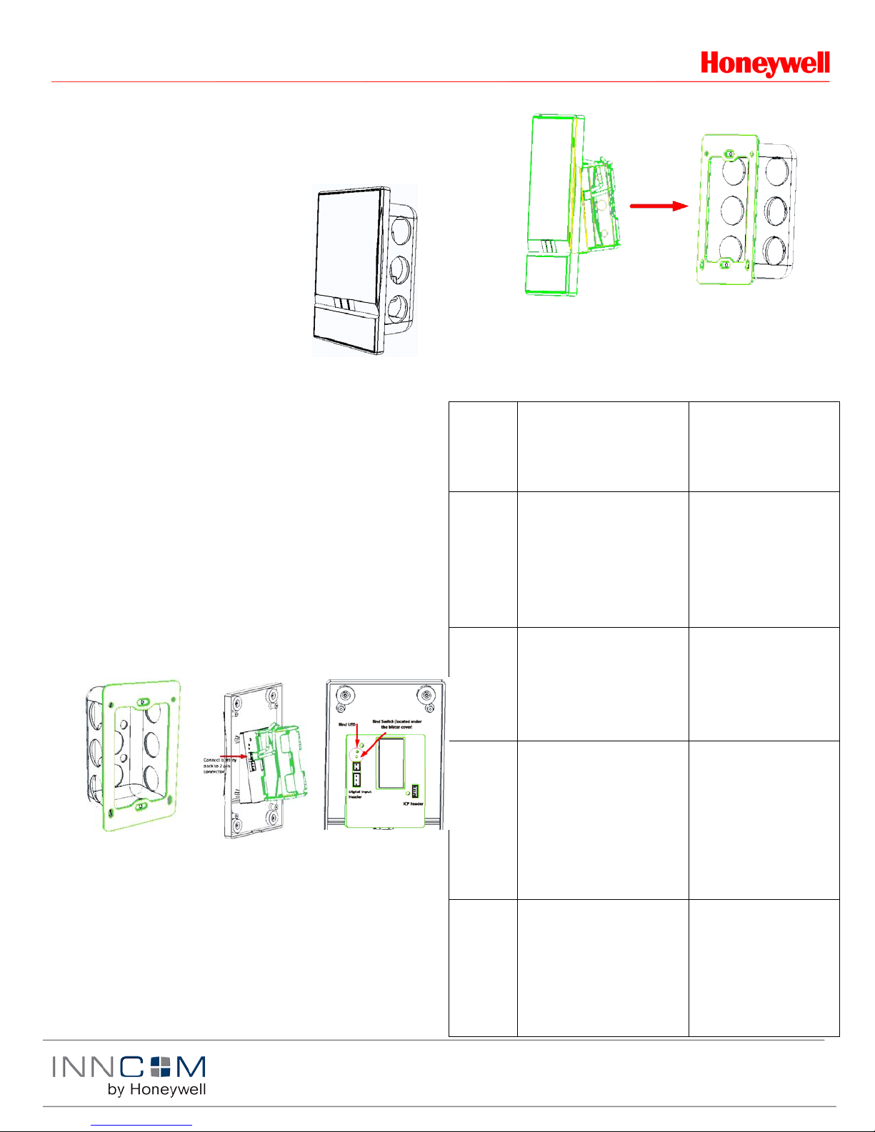
1. Install metal
2. Install the 4 AA
3. Bind the unit
4. After binding is complete; attach the unit to the wall mounting
K595 Installation Manual
K595 Overview
The K595 radio frequency (RF)
transmitter functions as a battery
powered motion sensor. It can
wirelessly transmit detected motion
information to the INNCOM E528
Deep Mesh thermostat or other
INNCOM Deep Mesh device that
requires motion detection for energy
management. The K595 is typica lly
used in conjunction with a door switch
in an energy management system.
Requirements
• K595 finished assembly
• 2 2 battery pack and 4 AA batteries
• I/O Map to be configured into K595 to set functionality (Table 1)
• E528 thermostat loaded deep mesh RF software
• E529.RF battery thermostat loaded with E529.RF Deep Mesh
software version 5.1 or later and radio software
DM_FPS_9600_V1_08.hex or later
Installation
• Mount within operational range (70 ft indoors) of any other Deep
Mesh devices
• Avoid interference sources like metallic boxes, WiFi access points,
or metal pipes
• Do not mount in areas of high humidity
bracket using
the two
supplied 6/32
screws to an
American
single gang
box. Careful
not to bend the
bracket.
bracket. Take care to align the guide posts so that the unit snaps
into place.
Prepare Binding Device with an e528.4G or E529.LX to Bind
Enter
Service
Parameter
Mode
OR
batteries into
the 2 x 2
battery pack
and attach it to
the 2 pin
connector on
the unit.
by pressing the
switch located
under the
blister cover in
the area
circled. Refer
to the “Binding”
Set Room
ID
Set PAN ID
Set RF
Channel
Set RF
Power
section of this
document.
1. Press and hold °F/°C button
2. Press and release the
OFF/AUTO button
3. Press and release the DISPLAY
button
4. Release the °F/°C button
1. Press the OFF/AUTO button
2. Use UP / DOWN arrow button to
find value. Press DISPLAY to
set.
3. Find/set value as above.
4. Find/set value as above.
1. In Service Mode, go to PAn
(PAN ID) on the display and
press the OFF/AUTO button.
2. Use the UP /DOWN buttons to
change the displ ay ed va lu e to the
desired PAN ID value.
3. Press the DISPLAY button to set
the new value.
1. In Service Mode, go to rF (RF
Channel) on the display and
press the OFF/AUTO button.
2. Use the UP /DOWN buttons to
change the displ ay ed va lu e to the
desired RF Channel value.
Only use the following RF Channels
to minimize interference with other
RF sources such as WiFi Access
points: 26 , 25 , 20 or 15.
1. In Service Mode, go to Loc (Local
Parameters) on the d is play and
press the OFF/AUTO button.
2. Change local parameter value to
4 (RF Tx Power) and p re ss
DISPLAY button.
3. Use the UP/ DOWN arrows to
change the RF Tx Pow er (de fau lt
value is 0—use a higher value
only to improve communication).
1. Screen displays rId
(RoomID)
1. Room ID scrolls. After
scrolling, highest Room ID
digit will display (=to PAR
10 on an E528)
2. Next 2 Room ID digits are
displayed (= to PAR 11)
3. Last 2 Room ID digits
display (=to PAR 12)
4. New Room ID scrolls
across display to confirm.
1. Current value displays.
2. Val ue chan ge s to a nu mber
between 1 and 255). [Note:
It cannot be set to 0].
3. E529.LX will beep to indicate
the value has been entered.
1. Current value displays.
2. Value changes to a nu mber
between 11 and 26 (default is
26).
3. E529.LX will beep to indicate
the value has been entered.
For multi-floor installations,
alternating RF Channel
between 25 and 26 can
minimize cross-floor
interference between
thermostat radios.
1. Display shows P and a
number represen t in g the
selected local parameter.
2. Loc value displays.
3. Press DISPLAY to set

Copyright 2013 INNCOM by Honeywell
12=6
radios.
I/O Map
Description
Default Address
0
Entry Door
209
1
Entry Door Inverted
209
2
Window
210 3 Window Inverted
210
4
Mini Bar
219
5
Mini Bar Inverted
219 6 Safe Inverted
219 7 Safe
219
8
Common Door
219
9
Common Door Inverted
219
10
Connecting Door
219
11
Connecting Door Inverted
219
12
Window Segment 0
211
13
Window Segment 0 Inverte d
211
14
Window Segment 1
212
15
Window Segment 1 Inverte d
212
16
Window Segment 2
213
17
Window Segment 2 Inverte d
213
18
Window Segment 3
214
19
Window Segment 3 Inverte d
214
20
Window Segment 4
215
PN 292-103
Binding
Prepare Binding with an E528.LX
Enter Service Parameter
Mode
Set Room ID
(PAR 10, 11, 12)
Set RF Transmit Power
and RF Channel
(PAR 243)
1
Press and hold °F/°C
button
Press and release the
OFF/AUTO butto n
Press and release the
DISPLAY button
Release the °F/°C button
Use OFF/AUTO and
UP/DOWN arrows to set
the Room ID in
parameters 10, 11 and 12.
Set PAR 243 to desired
RF Tx Power : RF
Channel
0dB : RF Channel 26
0dB : RF Channel 25
0dB : RF Channel 20
0dB : RF Channel 15
+3dB : RF Channel 26
+3dB : RF Channel 25
+3dB : RF Channel 20
+3dB : RF Channel 15
Only use the above RF
Channels to minimize
interference with other RF
sources such as WiFi
Access points.
Screen displays P1
(parameter 1)
Use UP / DOWN arrow
button to scroll through
parameters (1–255). Use
OFF/AUTO to toggle
parameter value V.
Examples:
RoomID=2456
PAR 10=0 PAR 11=24
PAR 12=56
RoomID=24351
PAR 10=2 PAR 11=43
PAR 12=51
RoomID=406
PAR 10=0 PAR 11=4 PAR
Displayed PAR 243 Va lue
0F.h
0E.h
09.h
04.h
1F.h
1E.h
19.h
14.h
For multi-floor
installations, alte rn atin g
RF Channel bet ween 25
and 26 can minimize
cross-floor interference
between thermostat
• For the E528.LX
o Go to Parameter 15 (target address for teach
commands).
o Press OFF/AUTO to view value.
o Change value using UP/DOWN arrows.
o Press OFF/AUTO to return to Parameter number mode
and scroll to Parameter 14.
o Press OFF/Auto to view value of I/O Map.
o Enter the number of the I/O Map (see Table1 below) to
be enabled in the bind.
• For the E528.4G and e529.LX, go to Adr (target address for
teach commands)
o Press OFF/AUTO to view value.
o Change value using the UP/DOWN arrows, then press
DISPLAY.
o Exit Adr using OFF/AUTO (display shows Pn6).
o Press UP 5 times until Io (teach I/O Map) displays.
o Press OFF/AUTO to view value and change it to the map
required for this installation (see Table 1 below).
o Press the blue S1 switch on the K595 to initiate binding.
The K595 will broadcast a Bind Request message. If the
thermostat saw the Bind Request, it will reply with a Bind
Offer message. Upon seeing the Bind Offer from the
E528/E529, the K595 will bind itself to the advertised
Room ID and RF Settings.
• If binding is successful, the K594 will
o Flash its LED 3 times
o Send the thermostat a message to sound its buzzer
o Reset itself
o Send a device startup message that includes the K595
software version and its battery status.
Note: The following table is for example only; the final
mapping will be determined by Appl icat ion Eng in eer ing,
and they should be consulted on any questions.
Set PAN ID
(PAR 242)
RESET E528.LX
Set PAR 242 to desired
PAN ID. The PAN ID can
be any value 1 to 255 and
must match the PAN ID
set into the PC-803 Edge
Router that manages this
room
Set PAR 1 value=0 and
press DISPLAY button
PAR 242 is displayed in
hex 01.h (1) to FF.h (255)
Ex:
PAN ID=45 – PAR
242=2d.h
PAN ID=150 –PAR
242=96.h
Binding the K595
The binding process for the K595 is depend ent on the
software. The K595 uses a reverse bind by first placing
the E528.LX/E529.LX into a “ready to teach” mode and
then initiating the bind from the K595 by pressing button
located under the blister cover.
1. Insert 4 AA batteries in the battery back and connect it to the
unit if not already installed
2. Enter the Service Parameter mode on the E528.LX/E529.LX
(as described above)
3. Prepare the thermostat to bind the K595
K595 I/O Maps
 Loading...