

Page 1

Rapid Eye Software
Using ADMIN and VIEW to Configure
Multi-Media Units and Manage Accounts
System Administrator’s Guide
Document K14392V1 – Rev A – 07/07
Page 2

Page 3

Revisions
Issue Date Revisions
K5403V10
Rev A
V10.B 2004, December Formatting: pagination; minor edits.
V11
Rev A
K14392
Rev A
K14392V1
Rev A
2004, October Honeywell template.
2006, January Updates to: time needed to clear storage, network address translation (NAT)
for connection to unit, NAT for connection to alarm station, continuous and
boosted settings for video recording, group of sites in Admin and View,
DSP Maxer, configuration—camera, enhanced preview, PTZ, PIT/NETPIT,
serial ports and removal of Restore button—, PTZ presets, PTZ controller,
video smoothing, user account: site and camera selection, resolution gauges
for live and recording, response schedule and rules, schedules’ GUI, motion
search reports, supported Microsoft Windows OS, LocalView: PTZ controller
and passwords.
2006, August Pub number changed. Re-formatting (headings, pagination, figure captions).
Added notes from previous release, updates to Scheduling: Configuration,
The Enhanced Preview of Resolution, Rapid Eye Storage Estimator, System
Clock: Manual Setting, Correcting the Clock, Programming a PTZ Dome
Camera, NetPIT and PIT Devices and new features: User Management,
Recording Video: Continuous Recording Settings, estimating the video
archive, using Audio and Support for Older Models of Units. Back cover
update, 21/08.
2007, July New features: ACUIX Dome Camera, Camera Sabotage: Detection.
Updates to: Start Here, Using Higher Values When Recording Video,
Simultaneous Sessions From One Unit and NetPIT and PIT Devices.
"Boosted" recording changed to "Event" recording, but a "Boost" button
remains. Section breaks added:
and Pan, Tilt, and Zoom (PTZ) Setup.
Multi-Media Site: Connection Configuration
Page 4

Page 5

Table of Contents
The Administration of a Rapid Eye System............................................ 19
Start Here..................................................................................................................................................................... 19
About Using a PC to Operate Rapid Eye Units ................................................................................................ 19
About Using LocalView Onsite .........................................................................................................................20
Using a PC: Installing Rapid Eye Software ................................................................................................................. 20
For the Multi SA Only: Admin and View Software ............................................................................................ 20
First Use: Running Admin Software ................................................................................................................. 21
Customizing a Unit: View Software................................................................................................................... 21
For Questions .............................................................................................................................................................. 22
Multi-Media Site: Name...........................................................................
Preparations ................................................................................................................................................................23
Site Setup: Checklist ................................................................................................................................................... 24
Naming / Renaming a Site ..........................................................................................................................................24
Site Naming Tips............................................................................................................................................... 25
After Dealing with a Site.................................................................................................................................... 25
Grouping Sites............................................................................................................................................................. 26
To Create a Folder ............................................................................................................................................ 26
To Assign a Site to a Folder.............................................................................................................................. 26
To Rename a Folder .........................................................................................................................................27
To Delete a Folder ............................................................................................................................................ 27
Grouping Folders.............................................................................................................................................. 27
Removing a Site ..........................................................................................................................................................28
To Delete a Site................................................................................................................................................. 28
Mistakenly Deleting a Secured Site Definition ................................................................................................. 28
23
Multi-Media Site: Connection Configuration.......................................... 29
Types of Connection ................................................................................................................................................... 29
Dial-up Connection: to a Unit...................................................................................................................................... 30
Setting a Dial-Up Connection ........................................................................................................................... 31
Area Code: Irregular Use ............................................................................................................................................ 32
To Force a Long-distance Dial-up Using a Local Area Code .......................................................................... 32
Forcing a Local Dial-up Across Area Codes ....................................................................................................33
Dial-up Technical Note ..................................................................................................................................... 33
Offering Many Dial-Up Connections to the Same Unit..................................................................................... 34
Using Network Access ................................................................................................................................................34
To Set a Network Connection........................................................................................................................... 35
Standalone Unit and a PC that Has a Network Card .......................................................................................36
Network Address Translation ...................................................................................................................................... 37
Adjusting a Unit’s IP Settings for NAT .............................................................................................................. 39
Setting a Router’s Mappings ............................................................................................................................40
Updating a Unit's Connection........................................................................................................................... 41
Refreshing the Multi-Media Local Db ...............................................................................................................41
Dynamic Host Configuration Protocol ........................................................................................................................41
To Configure DHCP Using Microsoft’s Server2000 (or 2003) ......................................................................... 41
Choosing the Computer Name or a Static IP................................................................................................... 42
Document K14392V1 Rev A 5
07/07
Page 6

Table of Contents
Many Connections to a Unit........................................................................................................................................
To Specify Dial-up and Network Connections .................................................................................................43
RAS Server ..................................................................................................................................................................44
Planning to Connect to One Unit at a Time...................................................................................................... 44
To Set a Connection to a RAS.......................................................................................................................... 45
Using a RAS Server before Connecting to a Unit ............................................................................................ 47
Connections: Report and Customization.................................................................................................................... 48
The Automatic Naming of Connections ...........................................................................................................48
Changing the Automatic Suffix in a Connection's Name .................................................................................48
Firewall: Technical Note .............................................................................................................................................. 49
Cascading Alarm Stations........................................................................................................................................... 49
To Sequence a Site’s Alarm Stations ............................................................................................................... 50
Quickly Assigning a Site to Many Alarm Stations ............................................................................................50
Setting a Site to Not Report Alarms to a Specific Station ................................................................................50
Customizing a Dial-Up Connection to an Alarm Station............................................................................................. 51
To Customize the Dial-up Connection to an Alarm Station .............................................................................52
To Cancel the Customization of a Telephone Number.................................................................................... 52
43
Unit Configuration: Basics...................................................................... 53
Maintenance Session .................................................................................................................................................. 53
To Start a Maintenance Session....................................................................................................................... 54
Support for Older Models of Units.................................................................................................................... 54
Making a Site Operational........................................................................................................................................... 55
Unit’s Time Zone and Clock........................................................................................................................................ 56
To Indicate the Time Zone of a Multi-Media Unit ............................................................................................. 57
Conflicting Time Zones..................................................................................................................................... 57
SNTP: Setting the Clock Automatically....................................................................................................................... 58
System Clock: Manual Setting .................................................................................................................................... 59
Adjusting the Clock on a PC Running Rapid Eye Software............................................................................. 59
Using a PC’s Clock to Set a Unit’s Clock Manually .........................................................................................59
Adjusting the Time on an Operational Unit ......................................................................................................60
Correcting the Clock......................................................................................................................................... 60
Securing a Site.................................................................................................................................................. 61
Rebooting a Unit ............................................................................................................................................... 61
Maintenance Reference .............................................................................................................................................. 62
Ending Maintenance ......................................................................................................................................... 62
Using Apply....................................................................................................................................................... 62
Maintenance Topics.......................................................................................................................................... 62
Maintenance Tasks ........................................................................................................................................... 63
Feedback Box Reference .................................................................................................................................64
Video Feed Setup.....................................................................................65
Cameras ......................................................................................................................................................................65
Renaming a Camera......................................................................................................................................... 65
Adjusting a Video Feed..................................................................................................................................... 66
To Re-enable One Camera's Feed ...................................................................................................................66
To Re-enable All Newly Connected, Powered Cameras.................................................................................. 66
To Adjust All Cameras at Once......................................................................................................................... 66
To Disable a Camera ........................................................................................................................................66
Resolution of Live Video in View Software .......................................................................................................66
Other Video Settings......................................................................................................................................... 67
Recording Video: Continuous Recording Settings..................................................................................................... 68
To Enable the Recording of a Video Feed .......................................................................................................68
6
Page 7

System Administrator’s Guide
Customizing Settings for Recorded Video..................................................................................................................
Resolution Setting............................................................................................................................................. 69
Frame Rate Setting ........................................................................................................................................... 70
Quality Setting................................................................................................................................................... 70
To Duplicate Settings........................................................................................................................................ 70
Continuous Recording and Event Recording ............................................................................................................. 71
Estimating Storage Capacity ............................................................................................................................ 71
Optimizing Recorded Video ........................................................................................................................................ 72
Automatic Maximization of DSP Performance.................................................................................................. 72
Making Optimized Resolution and Frame Rate Settings ................................................................................. 74
The Enhanced Preview of Resolution ......................................................................................................................... 74
Resolution Tips .................................................................................................................................................75
Comparing the Resolutions of Recorded Video............................................................................................... 76
Security and Presence...................................................................................................................................... 77
Camera Tips for Identification: Quality and Resolution.................................................................................... 79
Resolution Gauge for Retrieval Session........................................................................................................... 79
Resolution Reference: Recorded Video ........................................................................................................... 81
Customizing Windows for a PC Monitor’s Settings .................................................................................................... 82
PC Monitor’s Refresh Rate................................................................................................................................ 82
Microsoft Dual View and Rapid Eye View Software .........................................................................................82
Larger Monitors and Microsoft Windows.......................................................................................................... 83
Environmental Interference for Video Feeds ..............................................................................................................84
Physical Compromise....................................................................................................................................... 84
69
Pan, Tilt, and Zoom (PTZ) Setup............................................................. 85
Serial Device Settings for PTZ..................................................................................................................................... 85
To Assign and Set a New PTZ Device.............................................................................................................. 86
Video Tab Settings for PTZ .........................................................................................................................................86
To Enable a PTZ Camera ................................................................................................................................. 87
Using a PTZ Camera ................................................................................................................................................... 88
To Display the PTZ Dartboard Control ............................................................................................................. 88
Using the Dartboard Control............................................................................................................................. 89
Toggling between Zonal Mode and Pull Mode ................................................................................................ 89
Pulling the Rubber-Band................................................................................................................................... 90
Using Zonal Mode............................................................................................................................................. 90
Programming a PTZ Dome Camera ...........................................................................................................................91
To Configure a Preset on a PTZ Camera .........................................................................................................91
To Test a Preset ................................................................................................................................................ 92
Behavior of PTZ After a Session Closes........................................................................................................... 93
Support for RapidDome PTZ Features .......................................................................................................................95
RapidDome PTZ Tours .....................................................................................................................................95
RapidDome Mimic Tour .................................................................................................................................... 96
To Test a Mimic Tour on a RapidDome Camera.............................................................................................. 96
RapidDome Preset Tour ...................................................................................................................................96
To Setup a Tour of Presets on a RapidDome Camera .................................................................................... 97
Testing a Preset Tour on a RapidDome Camera ............................................................................................. 98
Privacy Zones for RapidDome.......................................................................................................................... 98
To Set a Privacy Zone....................................................................................................................................... 98
ACUIX Dome Camera.................................................................................................................................................. 99
Configuring the Intellibus Device for a Rapid Eye Unit .................................................................................... 99
To Configure an ACUIX Dome Camera for PTZ Use ..................................................................................... 100
Discovery of ACUIX Dome Cameras .............................................................................................................. 100
Backing Up an ACUIX Configuration File to a PC .......................................................................................... 100
Downloading a Configuration File to an ACUIX Dome Camera .................................................................... 101
Identifying the Model of the Camera ..............................................................................................................102
Upgrading the Firmware of an ACUIX Dome Camera ...................................................................................102
Document K14392V1 Rev A 7
07/07
Page 8

Table of Contents
Enhancing Video for Security ............................................................... 103
Event Recording: Configuration................................................................................................................................ 103
Using Higher Settings for Video Recorded During an Event ......................................................................... 103
Setting Lower Values for Continuous Recording ........................................................................................... 104
Event Recording on Demand, Using the Boost Button ................................................................................. 104
Automating Event Recording: Events of Interest ........................................................................................... 105
Scheduling: Configuration ........................................................................................................................................ 105
Making Use of a Schedule.............................................................................................................................. 107
To Add a Schedule .........................................................................................................................................107
Customizing a Schedule................................................................................................................................. 107
To Assign a Schedule to a Camera, or Group of Cameras ...........................................................................108
Using a 15-minute Increment in a Schedule .................................................................................................. 108
To Rename a Schedule ..................................................................................................................................109
To Delete a Schedule...................................................................................................................................... 109
Alarms and Scheduling................................................................................................................................... 109
Holiday and Exception.................................................................................................................................... 110
Adding Holidays and Exceptions ...................................................................................................................111
Event Recording for Video: Scheduling a Response ...............................................................................................112
Trigger: an Event of Interest ...........................................................................................................................112
Displaying the Response Panel Used for Making Rules................................................................................ 113
Checklist for Setting a Rule in the Response Schedule................................................................................. 113
Renaming a Rule............................................................................................................................................. 114
Rule Status: Icons ........................................................................................................................................... 114
Managing the Response to a Rule .................................................................................................................115
Assigning a Schedule to a Response Rule ....................................................................................................115
Disabling a Response Rule............................................................................................................................. 115
Motion Detection .......................................................................................................................................................116
To Configure Motion Detection....................................................................................................................... 117
Customizing Detection: Masking.................................................................................................................... 117
Example: Masking an Area of the Video Feed ............................................................................................... 117
To Mask Part of a Video Feed from Motion Detection ...................................................................................118
False Positives ................................................................................................................................................118
Customizing Detection: Scheduling ............................................................................................................... 118
Motion Detection Reference ........................................................................................................................... 119
Motion Search ...........................................................................................................................................................120
Camera Sabotage: Detection.................................................................................................................................... 120
To Configure CSD........................................................................................................................................... 121
Calibration of CSD ..........................................................................................................................................121
Moved-type CSD: Learning and Rearming Alarms ........................................................................................ 122
Computing the Length of the Video Archive............................................................................................................. 122
Rapid Eye Storage Estimator ......................................................................................................................... 123
Number of Cameras, Audio ............................................................................................................................ 124
Scheduling Cameras ......................................................................................................................................125
Frame Rate for Continuous Recording........................................................................................................... 125
Quality ............................................................................................................................................................. 125
Resolution .......................................................................................................................................................126
Using Higher Values When Recording Video ................................................................................................ 127
A Multi-Media Unit’s Storage Statistics ..................................................................................................................... 127
To Obtain a Unit’s Statistics............................................................................................................................ 128
8
Page 9

System Administrator’s Guide
Configuring Other Hardware ................................................................ 129
Clearing Storage ............................................................................................................................................. 129
Preventing Users from Clearing Storage........................................................................................................ 130
To Trace the Clearing of Storage ...................................................................................................................131
Updating Security on a Multi-Media Unit ..................................................................................................................131
System Files ..............................................................................................................................................................132
To Download a File from a Multi-Media Unit .................................................................................................. 132
System Tab in a Maintenance Session..................................................................................................................... 134
Logging System Messages ............................................................................................................................134
System Monitor ............................................................................................................................................... 134
Making the FAULT RELAY Operational .......................................................................................................... 135
Camera Signal Format.................................................................................................................................... 135
LAN/WAN Communications............................................................................................................................ 136
Changing a Unit’s Network Settings .............................................................................................................. 136
Changing the Maximum Network Data Rate .................................................................................................. 137
TCP Ports ........................................................................................................................................................ 137
Default System Values for a Multi-Media Unit ................................................................................................137
Serial Device: Modem ...............................................................................................................................................138
Viewing/Changing Modem Settings ............................................................................................................... 138
PPP: IP Settings Reserved for Modem Connection ....................................................................................... 139
To Set an External Modem .............................................................................................................................139
Serial Device: PTZ ..................................................................................................................................................... 140
To Assign and Set a PTZ Device .................................................................................................................... 140
Hardware Report .......................................................................................................................................................140
Public Display Monitor: Using Monitor Output 1 ......................................................................................................141
External Hardware Control of a Public Display Monitor................................................................................. 141
Using LocalView As an Additional Public Display Monitor ............................................................................ 142
Customer Data and Customer-Device Events .......................................................................................................... 143
Adding a Customer Device That Sends Data to a Unit .................................................................................. 143
Adding an Event Rule for a Data-recording Device ....................................................................................... 144
Search Rule and Regular Expressions: Reference ........................................................................................ 145
NetPIT and PIT Devices .................................................................................................................................. 146
Multi Audio................................................................................................................................................................. 147
Audio Hardware ..............................................................................................................................................147
Using Multi Audio............................................................................................................................................ 148
Audio Interference........................................................................................................................................... 148
Audio with LocalView ...................................................................................................................................... 148
To Enable Audio for Use Onsite, by LocalView.............................................................................................. 149
To Disable Audio for LocalView...................................................................................................................... 149
Multi-Media LT Audio Resources.................................................................................................................... 149
Eagle Audio..................................................................................................................................................... 149
Events ........................................................................................................................................................................ 149
Simultaneous Sessions From One Unit .................................................................................................................... 149
Simultaneous Use of Many Units by One Operator ................................................................................................. 150
Users...................................................................................................... 151
Key Facts ................................................................................................................................................................... 151
Before Creating User Accounts ...................................................................................................................... 152
Default User ............................................................................................................................................................... 152
User Management ..................................................................................................................................................... 153
Local User Management................................................................................................................................. 154
Central User Management.............................................................................................................................. 154
Setting a Unit to "Central" User Management ................................................................................................ 155
Document K14392V1 Rev A 9
07/07
Page 10

Table of Contents
Adding an Account, Using Admin and View.............................................................................................................
Naming Restrictions........................................................................................................................................ 156
User Groups.................................................................................................................................................... 157
Updating an Account ...................................................................................................................................... 157
Adding an Account in LocalView ..............................................................................................................................157
Updating an Account in LocalView................................................................................................................. 158
Granting Rights.......................................................................................................................................................... 158
To Customize the Rights in an Account ......................................................................................................... 158
To Base Rights On Those of Another User ....................................................................................................159
User Rights and Security ................................................................................................................................ 159
To Deny Access......................................................................................................................................................... 159
Removing a User's Account ...................................................................................................................................... 160
To Delete an Account Used Onsite, to Access LocalView............................................................................. 160
155
Security for a Multi-Media System .......................................................161
Security Options ........................................................................................................................................................ 161
Securing the Multi System ........................................................................................................................................161
Security Priorities ............................................................................................................................................ 162
Limiting the Use of Admin............................................................................................................................... 163
To Limit Access to Admin Documentation ..................................................................................................... 163
Password Guidelines ...................................................................................................................................... 163
Passwords....................................................................................................................................................... 164
Multi Database Security .................................................................................................................................. 165
SQL-Server Option.......................................................................................................................................... 165
SQL-server Type Logon, Reserved for Multi Operators................................................................................. 165
System Password...................................................................................................................................................... 166
Road Map to Setting the System Password................................................................................................... 167
Changing the System Password, Part 1 (of 3): Using Admin ........................................................................ 168
Changing System Password, Part 2: Multi-Media Units ................................................................................ 168
Changing System Password, Part 3: Updating Users ...................................................................................169
Status Report ..................................................................................................................................................169
Removing a System Password .................................................................................................................................169
Remove From All Units ................................................................................................................................... 170
Remove on One of Many Units....................................................................................................................... 171
System Password Extras ................................................................................................................................ 172
Replacing a Unit ........................................................................................................................................................ 172
To Replace a Unit when a System Password Is in Force .............................................................................. 173
Last Valid Password........................................................................................................................................ 174
If A Used Unit Comes from Another Multi System .........................................................................................174
To Re-en t e r a Site D e f initio n f o r a Unit w i t h a Syst e m P asswo r d ..............................................175
To Check if the Correct System Password Was Typed ................................................................................. 176
User Password ..........................................................................................................................................................176
Administrator Password.................................................................................................................................. 176
To Set the Administrator Account’s Password............................................................................................... 177
Rights of User Accounts............................................................................................................................................ 178
Guidelines ....................................................................................................................................................... 179
To View the Rights of a User and the Sites He may Access.......................................................................... 179
Right to Use Admin ......................................................................................................................................... 180
To Grant Access to Admin.............................................................................................................................. 180
Right to Use Maintenance............................................................................................................................... 180
Right to Use View............................................................................................................................................ 181
Right to Access a Site..................................................................................................................................... 182
To Define an Account’s Access to Certain Sites ............................................................................................ 182
Limiting the Time that a Unit Can Be Used ....................................................................................................183
To Limit Use of Cameras: Camera Partitioning .............................................................................................. 183
High-Security Considerations......................................................................................................................... 184
10
Page 11

System Administrator’s Guide
Events Defined ..........................................................................................................................................................
Setting an Event to Trigger an Alarm or to Be Logged .................................................................................. 187
Setting an Alarm.............................................................................................................................................. 188
To Set an Event to Report an Alarm ............................................................................................................... 188
Logging an Event............................................................................................................................................ 189
Event Reference ........................................................................................................................................................190
Tracing Events........................................................................................................................................................... 191
Event Session: to Search the Log of Events .................................................................................................. 193
To Input Times and Dates............................................................................................................................... 194
To Set the Date of a Retrieval Using the Calendar Utility............................................................................... 194
Results............................................................................................................................................................. 194
To Print a Log Entry ........................................................................................................................................ 194
System Failure........................................................................................................................................................... 194
A Multi-Media Alarm Station ...................................................................................................................................... 195
Alarm Notification: Response Priority............................................................................................................. 195
PPP Connectivity ....................................................................................................................................................... 196
Denying Access......................................................................................................................................................... 196
To Stop a Session on a Networked Multi-Media Unit ....................................................................................197
Denying Access .............................................................................................................................................. 198
To Deny Access to a User of Your Multi System............................................................................................ 198
Removing Multi-Media Software ...............................................................................................................................199
187
Multi-Media Alarm Stations .................................................................. 201
Overview .................................................................................................................................................................... 201
Checklist to Configure a Multi-Media Alarm Station ................................................................................................. 202
Operator Needs .............................................................................................................................................. 202
Multi SA Needs................................................................................................................................................ 202
System Administrator Needs .......................................................................................................................... 202
Adding an Alarm Station: Name and Reports .......................................................................................................... 203
Identifying and Defining a Connection ........................................................................................................... 203
The PPP Fields in an Alarm Station’s Definition............................................................................................. 204
Network Connection to an Alarm Station.................................................................................................................. 205
To Setup a Network Connection to an Alarm Station ....................................................................................205
Network Address Translation for Alarm Stations ........................................................................................... 206
To Prepare a Multi-Media Unit for NAT, Using Admin.................................................................................... 207
Dial-up Connection to an Alarm Station ................................................................................................................... 208
Preparing a Dial-up Connection to an Alarm Station ..................................................................................... 208
To Setup a Dial-up Connection to an Alarm Station ...................................................................................... 209
Entering Area Codes in Site and Alarm Station Definitions ...........................................................................210
Customizing a Dial-Up Connection to an Alarm Station ................................................................................ 211
To View “Update Station to Call in Case of Alarms” ...................................................................................... 213
To Use a Local Call Across Area Codes ........................................................................................................ 213
Toll-Free Numbers .......................................................................................................................................... 213
To Use a Long Distance Call in One Area Code ............................................................................................ 213
To Delay the Speed of Dialing ........................................................................................................................ 213
To Delay the Extension Suffix ......................................................................................................................... 214
International Dial-up........................................................................................................................................ 214
To Change Long-distance Prefixes ................................................................................................................215
RAS Connection to an Alarm Station ........................................................................................................................ 216
To Setup a Connection to a RAS Server ........................................................................................................ 217
Making an Alarm Station Operational ....................................................................................................................... 218
Using More than one Alarm Station ............................................................................................................... 218
Creating Extra Alarm Station Definitions for the same PC ............................................................................. 218
Disconnection Note ........................................................................................................................................218
To List Successful Alarm Callbacks after an Interruption .............................................................................. 219
Document K14392V1 Rev A 11
07/07
Page 12

Table of Contents
Removing an Alarm Station.......................................................................................................................................
Disabling/Enabling Dial-up Server.................................................................................................................. 219
Alarms from a De-listed or Unregistered Unit ........................................................................................................... 219
To Trace the Unit Sending the Alarm .............................................................................................................219
To Set a Site to Not Report to a Specific Alarm Station................................................................................. 220
219
Touring Many Sites................................................................................
Preliminary Checklist................................................................................................................................................. 221
Adding a Site Tour..................................................................................................................................................... 222
Default Amount of Time to Display a Unit During a Site Tour........................................................................ 222
Customizing a Tour ................................................................................................................................................... 223
To Change the Order of Sites in a Tour ......................................................................................................... 223
To Change the Time Spent at a Site, During a Tour ...................................................................................... 224
To Select Another Connection to a Site, During a Tour................................................................................. 225
Removing a Tour ....................................................................................................................................................... 225
221
Alarm Log............................................................................................... 227
Viewing the Log ......................................................................................................................................................... 227
To view the log................................................................................................................................................ 227
Sorting the Log ............................................................................................................................................... 228
Selecting Log Items ........................................................................................................................................228
Filtering the Log......................................................................................................................................................... 229
Printing the Log .........................................................................................................................................................229
To Print a List of Alarms.................................................................................................................................. 229
Archiving the Log....................................................................................................................................................... 229
To Archive Alarms........................................................................................................................................... 230
Removing Log Items .................................................................................................................................................230
To Delete Alarms............................................................................................................................................. 230
Alarm Log Data Reference.............................................................................................................................. 230
Multi Database ...................................................................................... 231
Starting Admin........................................................................................................................................................... 232
To Start Admin ................................................................................................................................................ 232
Obtaining a Multi db .................................................................................................................................................. 232
Using the Default Multi Db .............................................................................................................................. 233
Contrasting Db Engines.................................................................................................................................. 233
Using Another Db: Converting .................................................................................................................................. 234
To Use Another Multi Db................................................................................................................................. 234
Impact on View................................................................................................................................................ 235
Creating a Multi Db.................................................................................................................................................... 235
Naming Restriction ......................................................................................................................................... 236
To Create an Empty, MS-Access-Compatible Multi Db ................................................................................. 236
SQL-Server Template...................................................................................................................................... 237
An Empty Multi Database Using Microsoft SQL-Server ................................................................................. 237
Using Admin to Create a SQL-compatible Multi Database............................................................................ 238
Db Based On Another..................................................................................................................................... 239
To Make a Copy of a Multi Db ........................................................................................................................ 239
Renaming a Multi Db ......................................................................................................................................240
Multi Db: MinAdmin......................................................................................................................................... 240
Upgrading a Multi db................................................................................................................................................. 241
Upgrading a Local Database.......................................................................................................................... 241
To Upgrade a Local Database, without a Connection to the Multi Db ..................................................... 242
Producing a Local Database ..........................................................................................................................242
To Make a Local Database ............................................................................................................................. 242
12
Page 13

System Administrator’s Guide
Logging On................................................................................................................................................................
View: Setting the Db .......................................................................................................................................243
To Set a Multi Db for View .............................................................................................................................. 244
Refreshing a Local Database.......................................................................................................................... 244
To Refresh a Local Database while Running View......................................................................................... 245
Deleting a Database .................................................................................................................................................. 245
“Cannot Open Db”.......................................................................................................................................... 245
243
Index ...................................................................................................... 247
Figures
Figure 1–1. To Install View Software, Run the Multi-Media View CD-ROM. 20
Fig. 1–2. To Install Admin Software, Run the Multi-Media Admin CD-ROM. 20
Fig. 1–3. Desktop Icon for Admin software. 21
Fig. 2–1. Where to Click when Adding a Site. 24
Fig. 3–1. Selecting a Network or Dial-up Connection. 30
Fig. 3–2. Dial-up Connection. 30
Fig. 3–3. Automatic Tag Added to a Connection's Name. 31
Fig. 3–4. Irregular Use of Area Codes. 32
Fig. 3–5. Operating a Multi-Media Unit Over a Network. 34
Fig. 3–6. Site Tab’s Report of Primary Connections. 35
Fig. 3–7. Using a Direct Connection to Operate a Multi-Media Unit. 36
Fig. 3–8. NAT Configuration for Operating a Multi-Media Unit Over a WAN. 37
Fig. 3–9. NAT Configuration: Changing the IP Address of a Multi-Media Unit. 39
Fig. 3–10. NAT Configuration: Router Settings. 40
Fig. 3–11. Operating a Unit through Many Connections. 43
Fig. 3–12. Listing of Connections (Two) to a Site. 44
Fig. 3–13. Connecting to a Rapid Eye Site through a RAS Server, Transparently. 45
Fig. 3–14. RAS Server's Telephone Number and PPP Information. 46
Fig. 3–15. Connecting to a RAS Server, Before Running View to Operate Units. 47
Fig. 3–16. For Local Call s that Need an Area Code, Customize Dial-up. 51
Fig. 3–17. Customizing an Alarm Station’s Telephone Number. 52
Fig. 4–1. Multi-Media Unit Serial Number and Version of Unit Software. 55
Fig. 4–2. Unit Time Using SNTP as a Reference. 56
Fig. 4–3. Different Rules May Apply for Daylight Savings Time in one Time Zone. 58
Fig. 4–4. Setting a Multi-Media Unit’s Clock Manually. 59
Fig. 5–1. The Video Tab: Camera Names and Image Settings. 65
Fig. 5–2. The Video Tab: Color, Recording Settings, Motion and PTZ. 67
Fig. 5–3. The Recording Tab, Showing that Three Cameras Are Recording. 68
Fig. 5–4. A Red Dot Is Added to the Icon of a Camera that Is Recording. 69
Fig. 5–5. The Menu for Duplicating Recording Settings (1) or for Restoring Defaults (2). 70
Fig. 5–6. Estimating a Unit's Video Archive. 71
Fig. 5–7. Load on DSP Resources. 72
Fig. 5–8. The Automatic DSP Performance Maximization Window. 73
Document K14392V1 Rev A 13
07/07
Page 14

Table of Contents
Fig. 5–9.
Fig. 5–10. The Enhanced Preview Window. 75
Fig. 5–11. Using High or Moderate Resolution, 320 × 240 (NTSC), to Identify a Subject. 76
Fig. 5–12. Using Low Resolution, 160 x 120 (NTSC) to Show Presence. 77
Fig. 5–13. To Establish Presence, Lower-Resolutions May Suffice. 78
Fig. 5–14. Camera Distance Can Be more Important than High Resolutions. 79
Fig. 5–15. Resolution Gauge for Recordings Made with NTSC Cameras. 80
Fig. 5–16. Resolution Gauge for Recordings Made with PAL Cameras. 80
Fig. 5–17. Microsoft Windows’ Screen Area Settings. 83
Fig. 6–1. Assigning a PTZ Driver to a Port on the Multi-Media Unit. 85
Fig. 6–2. Configuration Settings (4) for a PTZ (3) Camera (2), on the Video Tab (1). 87
Fig. 6–3. Dartboard Control for PTZ camera, Showing Command Feedback. 89
Fig. 6–4. Dragging the Mouse Pointer in a PTZ Camera Window. 90
Fig. 6–5. Using PTZ Zonal Mode. 90
Fig. 6–6. PTZ Dome Camera without Auto-focus (1) or with, Between the Dots (2). 91
Fig. 6–7. Programming a PTZ Preset. 92
Fig. 6–8. Testing Presets on a PTZ Camera. 92
Fig. 6–9. PTZ Camera: Behavior after Use. 93
Fig. 6–10. Detail of PTZ Setup for the RapidDome Driver. 95
Fig. 6–11. Right-clicking in the Tour Programming table reveals the Insert command. 96
Fig. 6–12. Location of the Program Vector Button. 98
Fig. 6–13. Setting Up a Privacy Zone on a RapidDome PTZ Camera. 98
Fig. 6–14. Communication Settings for Intellibus on the Serial Devices Tab. 99
Fig. 6–15. The Manage Files Dialog Box. 101
Fig. 7–1. Continuous Recording and Event Recording, on the Recording Tab. 103
Fig. 7–2. Boost Button. 104
Fig. 7–3. Example of a Schedule Assigned to a Camera. 106
Fig. 7–4. Customizing a Schedule. 107
Fig. 7–5. Breakdown of a Cell into Fifteen-minute Sections. 108
Fig. 7–6. Using a Schedule for Alarms. 110
Fig. 7–7. Specifying a Holiday for the Next Few Years. 111
Fig. 7–8. A Rule's Trigger, Response and Schedule. 112
Fig. 7–9. Customizing a Rule: Visual Steps. 113
Fig. 7–10. Status Icons for a Response Rule. 114
Fig. 7–11. Motion Detection Configuration. 116
Fig. 7–12. Mask for Motion Detection. 117
Fig. 7–13. Motion Detection Menu. 119
Fig. 7–14. CSD Panel, on the Video Tab. 120
Fig. 7–15. Calibration of Blind-type CSD. 121
Fig. 7–16. Storage Estimator. 124
Fig. 7–17. Detail of the Statistics Tab, Showing Storage Statistics. 127
Fig. 8–1. Statistics Tab, Showing the Clear Storage Button. 129
Fig. 8–2. Securing a Unit, after Changing Passwords. 131
Fig. 8–3. File Transfers: to a Unit or from a Unit. 132
Fig. 8–4. Downloading the System.log File from a Multi-Media Unit. 133
Fig. 8–5. Enabling the FAULT RELAY. 135
Fig. 8–6. Enabling the FAULT RELAY Changes the Name of Output6. 135
Fig. 8–7. Serial Devices Tab Showing “Internal Port–Modem” Data. 138
Fig. 8–8. Monitor Out Tab, for a Multi-Media Unit’s MONITOR OUTPUT 1. 142
The Configure Automatic Optimizations Command. 74
14
Page 15

System Administrator’s Guide
Fig. 8–9.
Fig. 8–10. Some Devices can Be Searched for Data such as “No Sale”. 144
Fig. 8–11. Cash Registers, Connected to a Honeywell PIT. 146
Fig. 8–12. A NetPIT Device on PORT 3, Showing All Serial Interface Values. 146
Fig. 8–13. Expanded NetPIT device on PORT 3, showing three POS devices. 147
Fig. 8–14. Audio Tab. 148
Fig. 9–1. Button for Changing User Management from Local to Central. 154
Fig. 9–2. Adding a "Night Operator" Account. 156
Fig. 9–3. Defaults: User Account Rights (1) and Site Access (2). 158
Fig. 10–1. Logging on to SQL-Server Differs from the Log on to Admin. 166
Fig. 10–2. System Password. 166
Fig. 10–3. Securing a Unit. 167
Fig. 10–4. After Removing a System Password. 170
Fig. 10–5. The LVP Utility Is Used only when a Unit Replaces another at a Secured Site. 173
Fig. 10–6. Inputting a Previous Owner’s System Password into the LVP Utility. 175
Fig. 10–7. Assigning Rights to a “Night Operator” Multi-Media Account. 178
Fig. 10–8. Summary of a User’s Rights on the Users Tab. 179
Fig. 10–9. Account's Limit on Session Time, before Needing to Reconnect. 183
Fig. 10–10. Limiting an Account’s Use of Cameras at a Site. 184
Fig. 10–11. Identifying a Camera that is Not Recording, in a Live Session. 185
Fig. 10–12. Overriding a Camera that is not Recording, Using Event Recording. 186
Fig. 10–13. Sources of Events Include the Unit itself. 187
Fig. 10–14. Once Acknowledged, Alarms Are Entered into the Multi Db. 188
Fig. 10–15. A Multi-Media Unit Can Log an Event without Sounding an Alarm. 189
Fig. 10–16. Events Caused by a Multi-Media Unit or a View Operator. 192
Fig. 10–17. Search for Events Window. 193
Fig. 10–18. A Multi-Media Unit Can Be Set to Send Alarms to Specific PCs. 195
Fig. 10–19. Denying Access (1) and Updating Security for each Site in the Account (2). 198
Fig. 11–1. A Multi-Media Unit Can Send Alarms to a Specific PC. 201
Fig. 11–2. Over a Network, Alarm's Are Sent to an Alarm Station’s IP Address. 205
Fig. 11–3. Receiving Alarms from a Multi-Media Unit, over a WAN or the Internet. 206
Fig. 11–4. Connecting through a WAN to a Multi-Media Alarm Station on a LAN. 207
Fig. 11–5. To Report an Alarm, a Multi-Media Unit Can Call an Alarm Station. 208
Fig. 11–6. Area Code Input Is Needed to Reach a Multi-Media Alarm Station. 209
Fig. 11–7. Connection for an Alarm Station (1) Is Shown also in a Site's Definition (2). 210
Fig. 11–8. Irregular Use of Area Codes when Units Are Calling an Alarm Station. 211
Fig. 11–9. Customizing the Dial-up to an Alarm Station in the Site’s Definition. 212
Fig. 11–10. International Prefixes for Use of Rapid Eye Software in North America. 214
Fig. 11–11. International Prefixes for Use of Dial-up in Rapid Eye Software. 215
Fig. 11–12. A Multi-Media Unit Can Send Alarms through a RAS Server. 216
Fig. 11–13. RAS Configuration. 216
Fig. 12–1 . Adding a Tour Name. 222
Fig. 12–2. The Default Amount of Time for a Tour of each Unit. 223
Fig. 12–3. Customizing the Amount of Time that a Multi-Media Unit Is Toured. 224
Fig. 13–1. Alarm Log 227
Fig. 13–2. Possible Result of Sorting when Using “Month, Day, Year”. 228
Fig. 13–3. Filtering the Alarm Log. 229
Fig. 14–1. Data Flow from Admin to View. 231
Customer Devices can Include POS Units, such as Cash Registers. 143
Document K14392V1 Rev A 15
07/07
Page 16

Table of Contents
Fig. 14–2.
Fig. 14–3. Specifying the Multi Db. 234
Fig. 14–4. The Admin Logon Window. 235
Fig. 14–5. Copying Multi Db Data to another Multi Db. 239
Fig. 14–6. Options for Generating a MinAdmin Multi Db Template. 241
Fig. 14–7. The Log On to View. 243
Tables
Table 1–1 Customer Information: Checklist 22
Table 3–1 Possible Connections to a Rapid Eye Unit 29
Table 3–2 Multiple Dial-up Connections: Decision Chart 34
Table 3–3 IP defaults used by Multi-Media units 36
Table 3–4 Network Address Translation (NAT) Example 38
Table 3–5 Router Mappings: Example for Operation of Multi-Media Units 40
Table 3–6 Automatic Connection Names for a Rapid Eye Site 48
Table 3–7 Default Transmission Control Protocol (TCP) Ports 49
Table 4–1 Effect of Time Zone Setting on Display and Clips 57
Table 4–2 Maintenance Reference Topics 62
Table 4–1 When to Accomplish Maintenance Tasks 63
Table 4–2 Messages from a Unit, During a Maintenance Session 64
Table 5–1 Frame Rate Values (Approximate ips) for Multi-Media DSP Units 70
Table 5–2 Event Recording: Duty Cycle Cutoffs 72
Table 5–3 Recording Resolutions for Multi-Media DSP (pixel × pixel): NTSC and PAL 81
Table 5–4 Recording Resolutions for Multi-Media LT (pixel × pixel): NTSC and PAL 81
Table 5–5 Display Properties for Optimal Rapid Eye Video at Higher Resolutions 82
Table 6–1 PTZ drivers for controllers and domes 88
Table 6–2 Position after Close of Session, for PTZ Cameras 94
Table 6–3 Communications for the Intellibus Device, and for each ACUIX Dome Camera 99
Table 7–1 Contrasting Motion Detection and Motion Search 120
Table 7–2 Number of Cameras: Effect on the Video Archive* 124
Table 7–3 Scheduling of Cameras: Effect on Storage 125
Table 7–4 Frame Rate: Effect on Storage 125
Table 7–5 Impact of Quality Setting on a Unit’s Video Archive 126
Table 7–6 Recording Resolution: Effect on the Video Archive 126
Table 7–7 Available Storage: Comparing with One Camera to Nine 127
Table 7–8 Storage Statistics for a Multi-Media Unit 128
Table 8–1 Default Network Communications Settings 136
Table 8–2 System Tab: Default Values 137
Table 8–3 Default Modem and Dial-up Communications Settings 139
Table 8–4 Names of Temporary TCP/IP Addresses, for PPP 139
Table 8–5 Inputs for External Control of MONITOR OUTPUT 1 142
Table 8–6 Special Characters Available for a Search Rule 145
Table 8–7 Stream Availability 149
Admin Icon on the Windows Desktop. 232
16
Page 17

System Administrator’s Guide
Table 8–8
Table 10–1 Security Priorities 162
Table 10–2 System Password: Status 169
Table 10–3 Maintenance Tasks and Rights of a User Account 181
Table 10–4 Security Happenstance 185
Table 10–5 Event Reference, by Source and Tab 190
Table 10–6 Event: Default Settings for Log and Alarm 191
Table 11–1 Defining a Connection to an Alarm Station 203
Table 11–2 Connection Information Needed for a Rapid Eye site to an Alarm Station 204
Table 11–3 Router Mappings: Example for Unit Callback to Alarm Stations 208
Table 11–4 Area Code Matching, for Site and Alarm Station 211
Table 13–1 Logged Data 230
Table 14–1 A First Log On to Admin: Default Data for MS-Access 233
Maximum Simultaneous Sessions 150
Document K14392V1 Rev A 17
07/07
Page 18

Table of Contents
18
Page 19

The Administration of a Rapid Eye System
Start Here
Means of Configuring a Rapid Eye Unit
You have the option of configuring a Multi-Media DSP unit for CCTV use:
• Without using a personal computer (PC). Using LocalView, an interface that runs on the
Multi-Media DSP unit, to configure and operate a unit.
1
• Using a PC. Run Honeywell Rapid Eye Admin software for the administration of the Rapid Eye
system, and Rapid Eye View software, to operate Rapid Eye units.
• Using either.
Designated personnel: a Multi SA from your organization
To carry out the setup and supervision of Honeywell Rapid Eye™ Multi-Media DSP units, your
organization can designate a System Administrator (Multi SA) for your Rapid Eye CCTV system.
About Using a PC to Operate Rapid Eye Units
Using one Rapid Eye unit, or many at once
Admin software is used to manage a central database (Multi db) of Rapid Eye Multi-Media DSP
units. Older Rapid Eye units (Multi-Media and Multi models) are supported.
View software is used to further configure each of the Multi-Media DSP units for: video, audio, POS
devices and so on. View software can connect to many Rapid Eye units at once, for configuration
and for video, live and recorded, alarm sessions and so on.
The information in this guide (publication number K14392) deals almost exclusively with the use of
a PC to configure Rapid Eye units. For PC requirements, see the Please Read this First!, K14393.
Document K14392V1 Rev A 19
07/07
Page 20
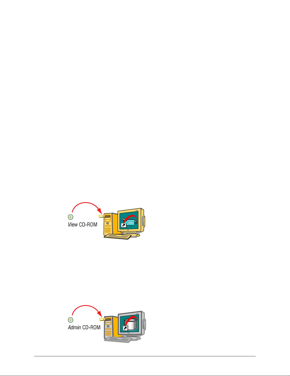
The Administration of a Rapid Eye System
About Using LocalView Onsite
Interface for operating one Rapid Eye unit
Configuration made using LocalView applies only to the unit on which it is running. To find out
how to use LocalView, the interface offers a context-sensitive Help system.
Network connection
If a unit is inserted in a common network, LocalView may be needed by installers to enter the
unit’s IP address. To do so, a Quick Install wizard is available when using LocalView. See the
Multi-Media DSP Unit: Quick Install broadsheet, K14355.
Watching your back
If Multi-Media DSP units are only operated remotely, from PCs, you have the option of preventing
the unauthorized use of LocalView by locking the interface, using passwords for LocalView.
Using a PC: Installing Rapid Eye Software
For Unit Operators: View Software Only
Personnel who operate Multi-Media DSP units—to monitor video, respond to alarms, make video
clips—only need View software on their PCs. Use the View CD-ROM to install View software only.
Figure 1–1. To Install View Software, Run the Multi-Media View CD-ROM.
For the Multi SA Only: Admin and View Software
The system administrator of your Rapid Eye system (Multi SA) needs Admin software and View
software. Use the Admin CD-ROM that came with your unit to install both. If security is important
to your organization, Honeywell recommends that the Admin CD-ROM be used only on the PC of
your organization’s Multi SA.
Fig. 1–2. To Install Admin Software, Run the Multi-Media Admin CD-ROM.
20
Page 21

First Use: Running Admin Software
The purpose of Admin software is to manage information in a Multi db. On first use, starting Admin
software is as simple as:
1. Double-click the Admin icon, shown in figure
Logon window appears.
2. If “Administrator” is not in the User ID box, type it.
3. Click OK .
Fig. 1–3. Desktop Icon for Admin software.
Rapid Eye central database
A Rapid Eye central database (Multi db) contains information about:
System Administrator’s Guide
1–3. The Rapid Eye Multi-Media Admin -
• Each Rapid Eye site. Network and dial-up communication settings for each Multi-Media DSP
unit. See Multi-Media Site: Connection Configuration, p. 29.
• Operator accounts. For Users of View software and Admin software, including passwords to
user accounts, see p.
• Rapid Eye alarm stations. PCs that receive alarms from Rapid Eye units. See
Alarm Stations, p.
• Site tours. Setup of lists of sites and time spent at each. Site tours work only if your
organization has two Multi-Media DSP units, or more. See
And so on.
151.
201.
Customizing a Unit: View Software
Using View software for site maintenance
After units are installed and a Multi db is created, View software is used to run a
Session. During a Maintenance Session, a unit’s settings can be changed:
Unit’s Time Zone and Clock. To identify recorded video, it is important to set a unit's time zone
•
and clock. See page
• Video. The resolution of recorded video can be set and the monitor settings of Microsoft
Windows can be adjusted. See
56.
Video Feed Setup, p. 65.
Multi-Media
Touring Many Sites, p. 221.
Maintenance
• Site hardware. View is used for unit and hardware settings. See
129.
p.
And so on.
Document K14392V1 Rev A 21
07/07
Configuring Other Hardware,
Page 22

The Administration of a Rapid Eye System
For Questions
In-depth reference
Most systems require only a few pages of this guide to make everything work. Use the table of
contents and index to locate the information that you need. This guide is also available in Adobe
Portable document format (PDF) while running Admin software, and can be searched using Adobe
Acrobat Viewer.
Configuration malfunctions
For problems with camera position, wiring, connections to other hardware, see the Unit Installation
Instructions , K14390 or please contact the installer of your Multi system.
In the figures: the names of places and people, the internet protocol (IP) addresses, and
other data are for illustration only and should only be a guide when running a Multi
system.
Calling Honeywell
Call Multi technical support for help with training or general problems. If you do call, please have
on hand the information listed in table 1–1. In North America the Multi technical support number is
1 (800) 796-2288. For other locations of Honeywell Video Systems, see the back cover of this
publication.
Table 1–1 Customer Information: Checklist
Information About Your Rapid Eye Multi System
The version of Windows used to run Admin on the PC, such as: Windows XP-Pro.
Connection type. If you are using a dial-up connection to the unit, a list of communication
tools used on the PC running Multi software: fax, AOL, CompuServe, and so on, the type of
modem, and the telephone number used. For a LAN connection, the Multi-Media unit’s IP
address, and so on. See Types of Connection, starting on p. 29.
The database used for your Multi db: SQL or Access; see
If you found information about the problem in the user guides.
Is a system password in use? See
System Password, p. 166.
Obtaining a Multi db, p. 232
22
Page 23

Multi-Media Site: Name
Preparations
Road map
A Multi-Media site refers to one Multi-Media unit. Even when there are many units at a “company
site”, each unit is considered as one Rapid Eye site. Before setting-up Rapid Eye sites for use by
View operators, your Multi System Administrator (Multi SA) should check if:
2
• Hardware at the Multi site is installed.
• Admin and View software are installed. See
• Multi central database is available. Obtained using Admin. See
• If the Time zone, Clock, the IP address of the unit may have been already set, onsite, using
LocalView. See the
Cameras
The Cameras... button is useful after you run a
assigned to each camera during the Maintenance Session.
Last valid password
Use of the LVP button is explained fully at
Uninformed use of the LVP utility can make a unit unusable and deny access to the unit for
all users, including a Multi SA. When adding a new Multi site to your Rapid Eye system,
do not use the “LVP" (last valid password) utility, even if you have set a system password
on other units.
The LVP utility is for dealing with replacement Multi-Media units, or mistakenly deleted sites; see
Last Valid Password, on p. 174.
Multi-Media DSP Unit: Quick Install broadsheet, K14355.
Right to Use Admin on p. 180.
Multi Database, p. 231.
Maintenance Session for the site. It lists the names
Last Valid Password, on p. 174.
Document K14392V1 Rev A 23
07/07
Page 24
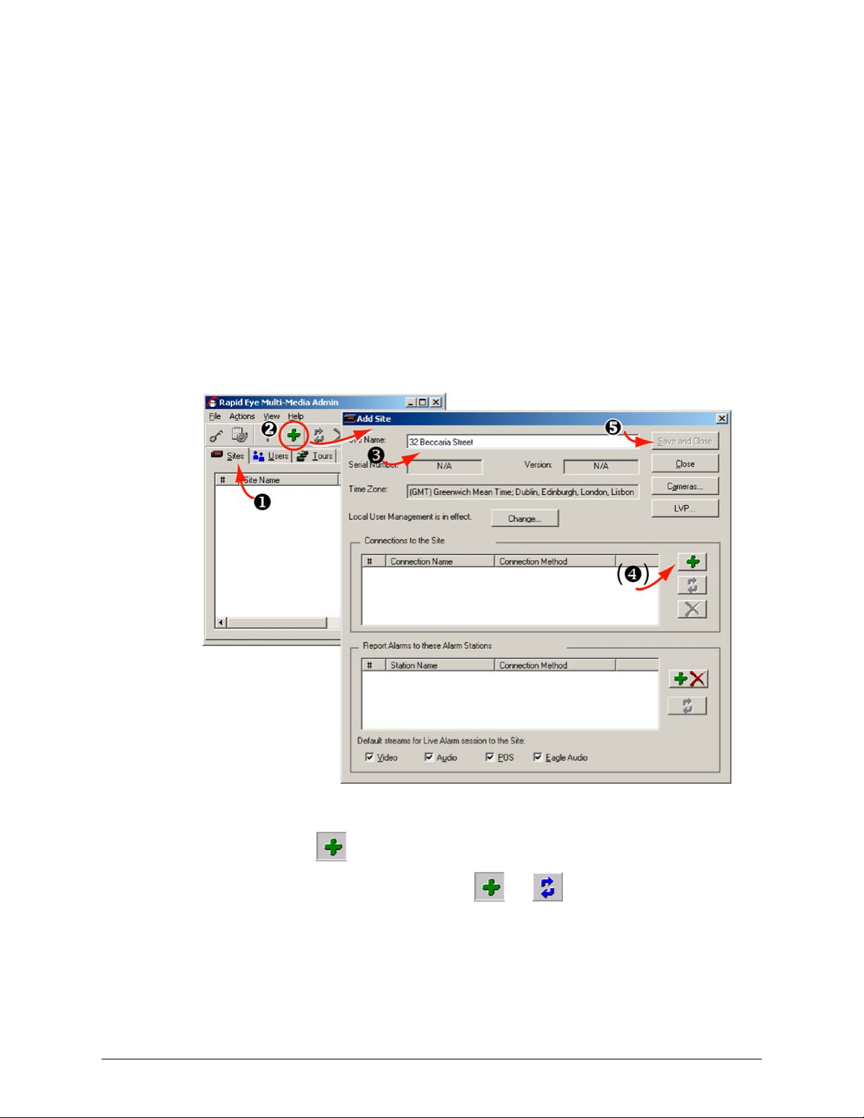
Multi-Media Site: Name
Site Setup: Checklist
Four items
• Name the site. See Naming / Renaming a Site.
• Identify the type of connections to the site and add them to the site definition. See Types of
Connection.
• Using View, start a Maintenance Session. See p. 53.
• Make the site operational by updating time zone, time and security, as explained in Making a
Site Operational, p.
55.
Naming / Renaming a Site
Fig. 2–1. Where to Click when Adding a Site.
24
1. Use Admin to display the Sites tab.
2. Display the Add Site dialog box. Click the pane on the right-hand side of the Sites tab,
then click
• Click the down-arrow between
appears, click Add Site.
• Click the pane on the right-hand side of the Sites tab; then click Add on the
Actions menu.
• Click the pane on the right-hand side of the Sites tab; press the Ctrl+Insert keys.
• Right-click in the pane on the right-hand side of the Sites tab; then click Add on
the menu that appears.
. You can also do any one of the following:
and on the toolbar. On the menu that
Page 25

3. Type a name in the Site Name box. The Multi-Media unit can be referred to by name.
4. Add a connection to the unit.
5. Click Save and Close.
Site Naming Tips
Try to use descriptive names: the address, area in the building, use of the facility and so on. The
goal is to avoid confusion in an emergency.
• Beware of placing an address next to a site number. Some addresses can lead to confusion.
For example:
“Site 26, 2607 Blue Jay Way” and
“Site 27, 2609 Blue Jay Way”.
A better alternative could be:
“site 26, corner house at 2607 Blue Jay Way”
“site 27, east parking lot, 2609 Blue Jay Way” or
“corner house at 2605 Blue Jay Way (site 26)”
“east parking lot, 2609 Blue Jay Way (site 27)”.
• Beware of long names that differ only at the end.
For example, avoid “parallel phrasing” to identify sites by building, floor, area and target can
lead to operator error due to a small difference only, located at the end of the identifier:
“Rosde building, 1st floor, mezzanine east, lobby entrance” and
“Rosde building, 1st floor, mezzanine east, lobby desk”
Better use of parallel phrasing could be:
“lobby, Rosde, mezzanine east” and
“front desk, Rosde, mezzanine east”.
System Administrator’s Guide
After Dealing with a Site
You have the option of using Admin to:
• Create users. The sites that a user can access are listed in a user’s account. See Granting
Rights, on p.
• Make the sites part of a site tour. After setting up a tour, View displays the sequence of video
feeds from different sites. See
• Alarm station. You can designate which alarm station(s) receives alarm reports. See
Alarm Stations. For procedures to connect Rapid Eye units to an alarm station, see
Alarm Stations, starting on p.
• Groups of sites. See
• System password. Use of a system password is highly recommended by Honeywell. After a
system password is set using Admin, update the security on each unit in your Rapid Eye
system. See
158.
Grouping Sites.
System Password, p. 166.
Touring Many Sites.
Cascading
Multi-Media
201.
Document K14392V1 Rev A 25
07/07
Page 26

Multi-Media Site: Name
Grouping Sites
Flexibility
Grouping sites is optional and applies only to organization's with two or more Multi-Media units.
Folders for grouping sites
As in a filing system, Multi-Media sites and Multi sites can be grouped, by assigning their names to
a folder. A site cannot be duplicated or copied to another folder.
To Create a Folder
1. Using Admin, click the Sites tab.
2. The many ways of creating a folder are for your convenience. Use any one. Either:
• Click the pane on the left-hand side of the Sites tab; then click Add on the Actions
• Click the pane on the left-hand side of the Sites tab; then press the Ctrl+Ins keys.
- or -
• Right-click in the pane on the right-hand side of the Sites tab; then click Add on
menu.
the menu that appears.
3. Click the arrow in between the
the menu that appears.
4. Type a name in the box next to the folder icon.
5. Save the name by either: pressing the Enter key or click outside of the box holding
the name.
To Assign a Site to a Folder
Do any of the following:
• Using the mouse, click and drag a site; drop it on a folder. When the mouse button is released,
the folder into which the site was dropped is opened.
• A site can be assigned from a folder back to the root of the database in the same way: by
clicking and dragging the site from the folder.
• One or many sites can be assigned to a folder at the same time. Press the Ctrl key while
selecting sites that are not sequential in a list; then drag the lot to another folder or the root.
Holding the Shift key while clicking sites selects those sites and all sites in between.
and on the toolbar; then click Add Folder on
26
Page 27

To R e n a m e a Fo l d e r
1. Using Admin, click the Sites tab.
2. Select a folder; then, either:
• Click the folder’s name again, once.
• Click , on the toolbar
- or -
• Right-click the folder’s name; then click Update on the menu that appears.
3. Save the folder’s name. Either:
• Press the Enter key
• Click elsewhere in the View window
- or -
• Switch to another Windows application.
To Delete a Folder
System Administrator’s Guide
1. Using Admin, click the Sites tab.
2. Click a folder.
3. Either:
• Press the Delete key on the keyboard,
• Click Delete on the Actions menu, or click on the toolbar.
• Right-click the site name; then click Delete on the menu that appears.
4. If the folder you are deleting contains a site or a folder and so on, the folder’s contents
are listed. To confirm that you want to delete the folder, click Yes.
Grouping Folders
Folders can be assigned to other folders or back to the root of the database. The same name can
be used for two folders that are not in the same branch.
To assign a folder to a folder
• Using the mouse, click and drag a folder; drop it on another folder. When the
• Assigning a folder to another, or the to the database root, also assigns its
mouse button is released, the folder into which the folder was dropped is
opened.
contents, including sites and sub-folders.
To collapse or expand sub-folders
Either double-click a folder or click + or - on the folder’s left. These + and - act as a toggle:
alternately expanding and collapsing a set of sub-folders.
Document K14392V1 Rev A 27
07/07
Page 28

Multi-Media Site: Name
Removing a Site
Honeywell recommends that before deleting a site definition, you remove the system password
from that Multi-Media unit. See
remove the system password from all sites; only on the unit being deleted from your Multi db.
If the site password is not removed from the unit, you will need to remember it when you
create another site definition for that Multi-Media unit. The system password is also
To Delete a Site
needed if you delete a site definition by mistake.
Deleting a site in the Multi central database has no effect on the Multi-Media unit at that site. The
unit continues to record video, send alarms and so on, even once the local databases of users are
refreshed. The unit’s system password remains in force.
1. You have the option of going to the Rapid Eye Site to physically disconnect the MultiMedia unit from its means of communications.
2. Check if a system password is in use. If so, you have the option of removing the system
password from the Multi-Media unit. If you do not need to protect the video and other
recorded data from access, it is strongly recommended that you remove the system
password from the unit. See
Removing a System Password, on p. 169. You do not need to
Removing a System Password, on p. 169.
3. Using Admin, select a site name, listed on the Sites tab.
4. Remove the site by either:
• Press the Delete key on the keyboard,
• Click Delete on the Actions menu, or click on the toolbar.
• Right-click the site name; then click Delete on the menu that appears.
5. The site’s dependencies are listed. Confirm that you want to delete the site.
Mistakenly Deleting a Secured Site Definition
When a system password is in use and a site is deleted by mistake, you need a few extra steps to
re-enter the site definition. The system password is left in use on the unit, by default. For the
procedure to re-enter information about a mistakenly deleted site that is protected by a system
password, see
Renaming a Site, on p.
Last Valid Password, on p. 174. You can read about how to add a site in Naming /
24.
28
Page 29

3
Multi-Media Site: Connection Configuration
Types o f C onnec t i on
Connections can be: dial-up or network. Alternatively, a direct connection between a PC and a unit
can also be used. A connection is not needed to use LocalView. A checklist of the information
needed for each type of connection is listed in table
Table 3–1 Possible Connections to a Rapid Eye Unit
3–1.
For a Connection Using … A Multi SA Needs …
dial-up to a remote Multi-Media unit - telephone number to reach unit, p. 30
dial-up making irregular use of an area code. - telephone number to reach unit, p. 30
- to customize a dial-up connection, p.
network access - standalone PC with network card, p.
- IP address of the unit, p. 34, or
DHCP available on the network, p. 41
- open port in firewall, p. 49
a combination of dial-up or network access - IP address of the unit, p.
- port in firewall, p.
- telephone number to reach unit, p. 30
including a remote access service (RAS) server in a
connection to a Multi-Media unit. Requires
overriding point-to-point protocol (PPP).
dial-up to a RAS server, before accessing one or
many Multi-Media units at once, on the same
remote network
Naming and viewing a connection
- RAS server account, p.
- its PPP password, p.
- telephone number to reach RAS
- IP address of Multi-Media unit(s), p. 47
- port in firewall, p. 49
- IP address of Multi-Media unit, p. 47
- PPP password, p.
- telephone number to reach RAS
- port in firewall, p.
- PC operator: needs RAS account, p.44
43
49
44
196
196
49
32
36
Connections are named automatically, but they can be renamed. See
Connections, p.
The primary connection of a site is displayed on the Sites tab; See figure 3–6, p. 35.
Document K14392V1 Rev A 29
07/07
48, and Changing the Automatic Suffix in a Connection's Name, p. 48.
The Automatic Naming of
Page 30
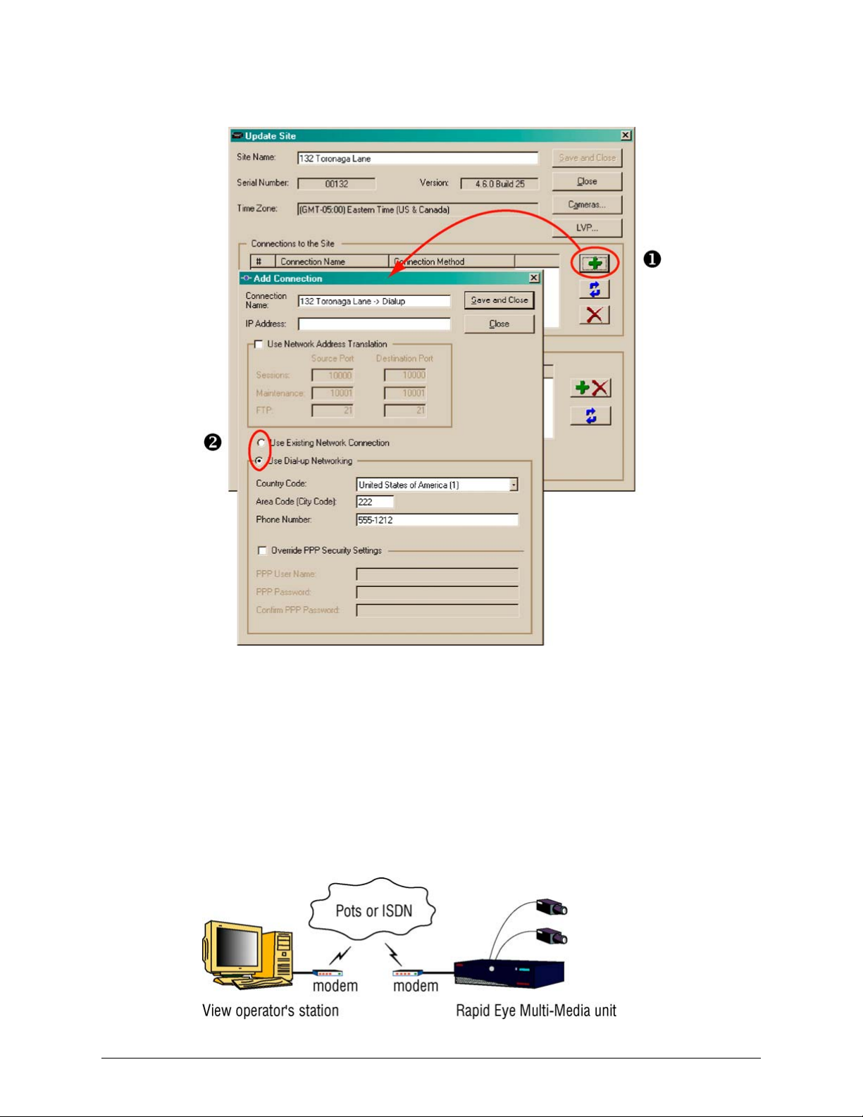
Multi-Media Site: Connection Configuration
Fig. 3–1. Selecting a Network or Dial-up Connection.
Dial-up Connection: to a Unit
Using a modem (i.e., dial-up), an operator can connect to a Multi-Media unit. The modems can be
internal or external.
A dial-up connection is optional. For other means of connecting to a Multi-Media unit, see
3–1 on p. 29.
table
Fig. 3–2. Dial-up Connection.
30
Page 31

Setting a Dial-Up Connection
Fig. 3–3. Automatic Tag Added to a Connection's Name.
System Administrator’s Guide
1. While adding a site (as in
in the “Connections to the Site” pane. The Add Connection dialog box is displayed.
Leave the IP Address box empty for a dial-up connection to a Multi-Media unit.
2. Click Use Dial-up Networking. See figure
connection in the Connection Name box from “-> Network" to “-> Dialup”. See fig.
You have the option of keeping the name or of typing another.
3. Leave the Country Code to “(dialing same country)”, unless the Multi-Media unit is in a
different country than the View operator planning to use the site.
4. Type the unit’s Area Code (City Code) and Phone Number obtained from your network
administrator (this is mentioned in section
needed to access an outside line, set the prefix—the extra telephone keystroke such as
a “9” or an “8”—in Window's Telephony program.
5. Click Save and Close. An “Add Site / Update Site” window is displayed.
6. Click Close. The Sites tab appears. In the tab’s Primary Connection column, the first
letter of “dial-up” appears in parentheses: (d), followed by the telephone number used to
connect to the Multi-Media unit.
Should you plan to add alarm stations, dial-up connections from a Multi-Media unit to an alarm
station are explained in section
Naming / Renaming a Site, above) or updating one, click
3–3, above. Admin automatically names the
Preparations, on p. 23). If a prefix number is
Dial-up Connection to an Alarm Station, on p. 208.
3–3.
Document K14392V1 Rev A 31
07/07
Page 32

Multi-Media Site: Connection Configuration
Area Code: Irregular Use
Fig. 3–4. Irregular Use of Area Codes.
Irregular use of area codes occurs when making:
• A long distance call within one area code.
• A local call to another area code.
You can easily deal with these scenarios (see figure
another dial-up connection. If a prefix number is needed to access an outside line, set the prefix—
the extra telephone keystroke such as a “9” or an “8”—in Window's Telephony program.
3–4, above) by using Admin to modify or add
To Force a Long-distance Dial-up Using a Local Area Code
1. In the “Connections to the Site” pane of the Add Site / Update Site dialog box (as in
Naming / Renaming a Site), click either:
, to add a connection. The Add Connection dialog box appears.
- or -
, to update a connection. The Update Connection dialog box appears.
2. Click Use Dial-up Networking as needed.
3. In the Connection Name box, you have the option of appending a few words such as
“force long distance call”. It makes sense to do so, to avoid confusing operators of View.
32
4. In the Phone Number box, type the telephone number needed to reach the unit,
including country and long distance codes.
5. Leave the Country Code and Area Code (City Code) boxes empty. Steps 4 and 5 fool
Windows’ Dial-up Networking into making a local call across different area codes. Click
Save and Close. An “Add Site / Update Site” window is displayed.
6. Click Close. The Sites tab appears In the tab’s Primary Connection column, the first
letter of “dial-up” appears in parentheses: (d), followed by the telephone number used to
connect to the Multi-Media unit.
Page 33

Forcing a Local Dial-up Across Area Codes
1. In the Add Site/Update Site dialog box (as in Naming / Renaming a Site), in the
“Connections to the Site” pane, click either:
, to add a connection. The Add Connection dialog box appears.
- or -
, to update a connection. The Update Connection dialog box appears.
2. Click Use Dial-up Networking.
3. In the Connection Name box, append a suggestive name such as “force local call”.
4. In the Phone Number box, type only the telephone number needed to reach the unit.
5. Leave the Country Code and Area Code (City Code) boxes empty. Steps 4 and 5 fool
Windows’ Dial-up Networking into making a local call across different area codes.
6. An “Add Site / Update Site” window is displayed.
7. Click Close. The Sites tab appears In the tab’s Primary Connection column, the first
letter of “dial-up” appears in parentheses: (d), followed by the telephone number used to
connect to the Multi-Media unit.
System Administrator’s Guide
Dial-up Technical Note
PPP
During a dial-up connection, temporary TCP/IP network communications are established between
the Multi-Media unit and the PC. These default point-to-point protocol (PPP) Internet Protocol (IP)
settings can be changed, should they conflict with other network devices (printers, scanners and
so on). See
Should you plan to add an alarm station
Should you plan to add one or more alarm stations using dial-up connections, Honeywell
recommends that area codes be included in all telephone numbers. Dial-up connections between
a Multi-Media unit and an alarm station running View are explained in
Alarm Station, on p. 208.
Serial Device: Modem, on p. 138.
Dial-up Connection to an
Document K14392V1 Rev A 33
07/07
Page 34

Multi-Media Site: Connection Configuration
Offering Many Dial-Up Connections to the Same Unit
More than one dial-up connection to the same Multi-Media unit may be needed. Table 3–2 lists
configurations, and the number of connections for best results. For example, Windows Dial-Up
Networking can give unwanted results when some View operators are inside the Multi-Media unit’s
local calling area and others are outside. Telephone companies can also force a Multi SA to setup
an irregular local call—a local call across area codes.
Table 3–2 Multiple Dial-up Connections: Decision Chart
Operator’s
PC (location)
in unit’s
calling area
irregular long distance:
irregular long distance:
outside unit’s
calling area
irregular local call: not
some in,
some out of
unit’s calling
area
in another
country
some out of
site’s country
Call to Unit
(type)
local Dial-up Connection: to a Unit, p. 30 1
same area code
local call
long distance
requiring area code
permutations of all of
the above
international long
distance
all permutations Dial-up Connection: to a Unit, p. 30
Procedure
(name, page)
Area Code: Irregular Use, p. 32 1
Dial-up Connection: to a Unit, p. 30
& Area Code: Irregular Use, p. 32
Dial-up Connection: to a Unit, p. 30 1
Area Code: Irregular Use, p. 32 1
Dial-up Connection: to a Unit, p. 30
& Area Code: Irregular Use, p. 32
Dial-up Connection: to a Unit, p. 30 1
& Area Code: Irregular Use, p. 32
Connections
(number of)
2
from 2 to 4
from 2 to 5
Using Network Access
Fig. 3–5. Operating a Multi-Media Unit Over a Network.
Flexibility
A network connection is optional. For other means of connecting to a Multi-Media unit, see table
3–1 on p. 29.
34
Page 35

To Set a Network Connection
1. In the Add Site/Update Site dialog box, click in the “Connections to the Site” pane.
The Add Connection dialog box appears. In the Connection Name box, a stylized arrow
and “Network” are appended to the site’s name.
2. Before typing into the IP Address box, find out whether you are dealing with a:
• - Common network, without DHCP (or with DHCP disabled) -
type a static IP address, obtained from the unit’s installer or network administrator, as
mentioned in section
• - Standalone unit (unit not on a network and the PC that runs Admin software has
a network card) type a static IP address. You can match the network settings of Microsoft
Windows running on the PC to either the unit’s default, listed in table
p. 36. See Standalone Unit and a PC that Has a Network Card.
• - One IP for many destinations -
type the static IP address of an internet router. Network address translation (NAT)
and port address translation (PAT) values are obtained from the network
administrator; see
• - Network using DNS and a DHCP server -
Obtain the site serial number, printed on a sticker affixed to the unit, for use in the
computer name for the Multi-Media unit. The format for the name is:
“REM[hyphen][site serial number (without the leading zeroes)]”. For example:
REM–7654321. Type this computer name in the Connection Name box. See also
Dynamic Host Configuration Protocol.
• - DHCP server, without DNS -
type the IP address reserved by DHCP for the unit. Contact the administrator of
your network, to obtain a reserved IP address; otherwise the address will change,
compromising attempts to connect to the unit. See Dynamic Host Configuration
Protocol.
3. Name the connection, either by:
• Leaving the name set by Admin in the Connection Name box.
• Typing another name in the Connection Name box.
4. Click Save and Close. The “Add Connection” window remains open.
5. Click Close. The Sites tab appears. In the tab’s Primary Connection column, the first
letter of “network” appears in parentheses: (n), followed by the IP address used to
connect to the Multi-Media unit. See figure
Naming / Renaming a Site. Continue this procedure.
Network Address Translation, p. 37.
System Administrator’s Guide
3–3 on
3–6.
Fig. 3–6. Site Tab’s Report of Primary Connections.
Document K14392V1 Rev A 35
07/07
Page 36

Multi-Media Site: Connection Configuration
Standalone Unit and a PC that Has a Network Card
To use a direct connection to a Multi-Media unit, you need a network crossover cable.
Fig. 3–7. Using a Direct Connection to Operate a Multi-Media Unit.
Tip
For other means of connecting to a Multi-Media unit, see table 3–1 on p. 29.
LocalView
For a single Multi-Media unit or Multi-Media LT unit, onsite operators have the option of using
LocalView instead of a PC. See
Network-like connection
For standalone PCs connected directly to a unit, using a network crossover cable, use a network
connection. Match the network settings of Microsoft Windows running on the PC to the default
address, subnet mask and gateway of the Multi-Media unit. The defaults are listed in table
below.
Static network settings, default for Multi-Media unit
The defaults in table
• View, to run a
• LocalView, onsite.
Table 3–3 IP defaults used by Multi-Media units
Point Address
IP Address 172.25.2.1
Subnet Mask 255.255.0.0
Gateway 172.25.100.4
3–3 can be changed using:
Maintenance Session. See System Tab in a Maintenance Session, on p. 134.
About Using LocalView Onsite, on p. 20.
3–3,
36
Page 37

Network Address Translation
In a nutshell
A connection to one or many Multi-Media units, using one IP address, can be made by using
network address translation (NAT) also called port address translation (PAT). This is useful to
connect to Multi-Media units through: a WAN, the Internet or to another segment of the same
LAN. The key is to configure a router to translate and map the Sessions source IP port.
IP Addresses
The Network Administrator of the destination’s LAN can supply a Multi SA with:
• the Inside IP address and Outside IP address of the internet router
System Administrator’s Guide
• the LAN IP addresses that are assigned to each unit. See the example in table
IP Port
For each Multi-Media unit on a remote LAN, set a different router Sessions value, under Source
Ports, in the Add Connection/Update Connection dialog box of Admin software. Figure
shown further below, shows where to enter this value. The router uses the value to route
commands to the proper unit, on the remote LAN.
Fig. 3–8. NAT Configuration for Operating a Multi-Media Unit Over a WAN.
3–4, below.
3–10,
Document K14392V1 Rev A 37
07/07
Page 38

Multi-Media Site: Connection Configuration
Table 3–4 Network Address Translation (NAT) Example
Item Data Field IP Address/Port Data Source/Comment
router router’s software
WAN / Outside IP*
Multi-Media Connection dialog box in Admin software
unit “A” IP Address
Session Source Port
System tab in View software
(Inside) IP Address
Connection dialog box in Admin software
unit “B” IP Address
Session Source Port
System tab in View software
(Inside) IP Address
LAN / Inside IP*
Port(s)
Subnet Mask
Gateway
Subnet Mask
Gateway
164.178.32.59
192.168.101.1
For port mappings,
see table
164.178.32.59
49,200
192.168.101.2
255.255.255.0
192.168.101.1
164.178.32.59
49,300
192.168.101.3
255.255.255.0
192.168.101.1
3–5, p. 40.
Used also in Admin for
the connection definition.
Is also unit’s IP gateway
map source to destination
router: Outside IP address
Multi SA
Network Admin
Network Admin
router: Inside IP address
router: Outside IP address
Multi SA
Network Admin
Network Admin
router: Inside IP address
* The name of the data field may vary. See the router’s documentation.
Four procedures are needed to setup a connection to use NAT:
Adjusting a Unit’s IP Settings for NAT
•
•
Setting a Router’s Mappings
Updating a Unit's Connection and
•
Refreshing the Multi-Media Local Db.
•
For each Multi-Media unit on the destination LAN, use these procedures.
38
Page 39
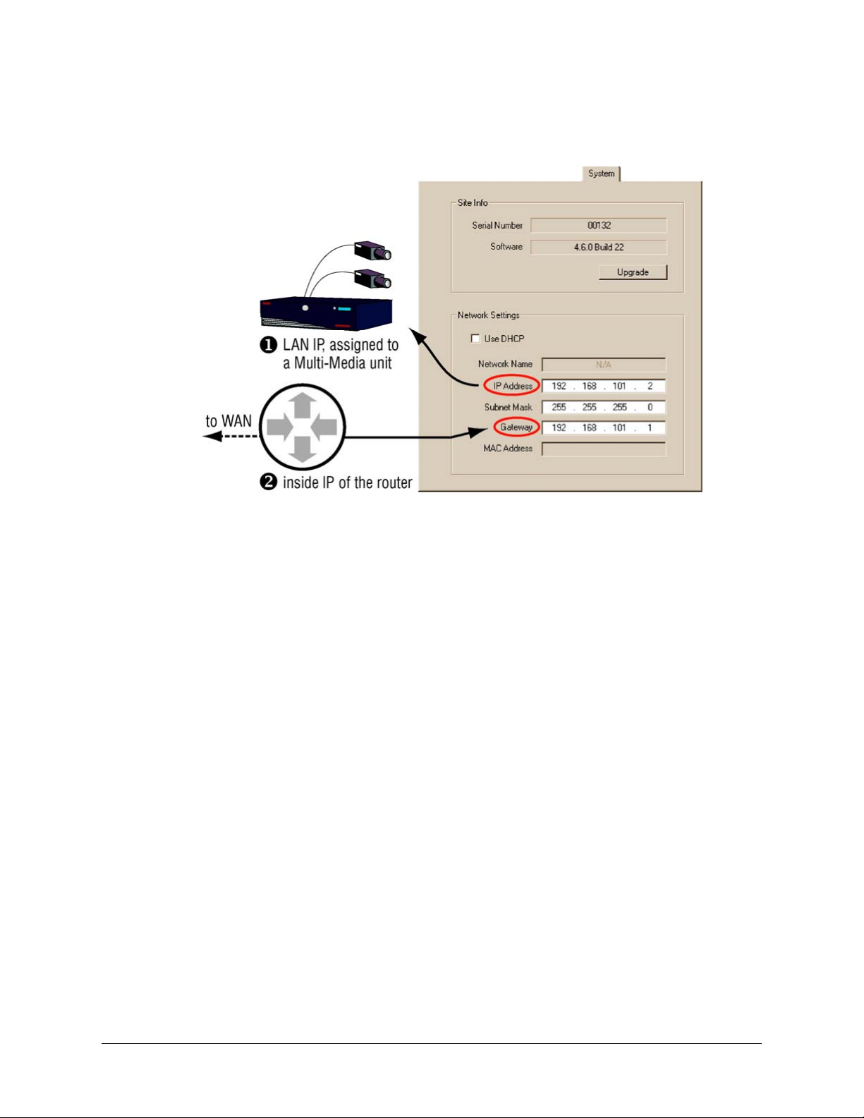
Adjusting a Unit’s IP Settings for NAT
Fig. 3–9. NAT Configuration: Changing the IP Address of a Multi-Media Unit.
System Administrator’s Guide
1. Ask the network administrator of the remote LAN for the unit’s:
• IP Address
• Subnet Mask
• Gateway. The Gateway on the unit matches the router's Inside IP address; for
example, in figure
2. Enter the values obtained in step 1 using either:
• LocalView software, onsite. Click the Setup tab and then click the System tab.
Use the buttons in the Network Settings box.
- or -
• A PC that runs View and that can connect to the Multi-Media units. Run a
Maintenance Session to the unit. The values are entered on the System tab. See
figure
3–9. This locks out View operators from further use of the unit until the
router and Multi db are updated. See
a Unit's Connection. Operators using LocalView are not locked out.
3–9, it is set to 192.168.101.1.
Setting a Router’s Mappings and Updating
Document K14392V1 Rev A 39
07/07
Page 40
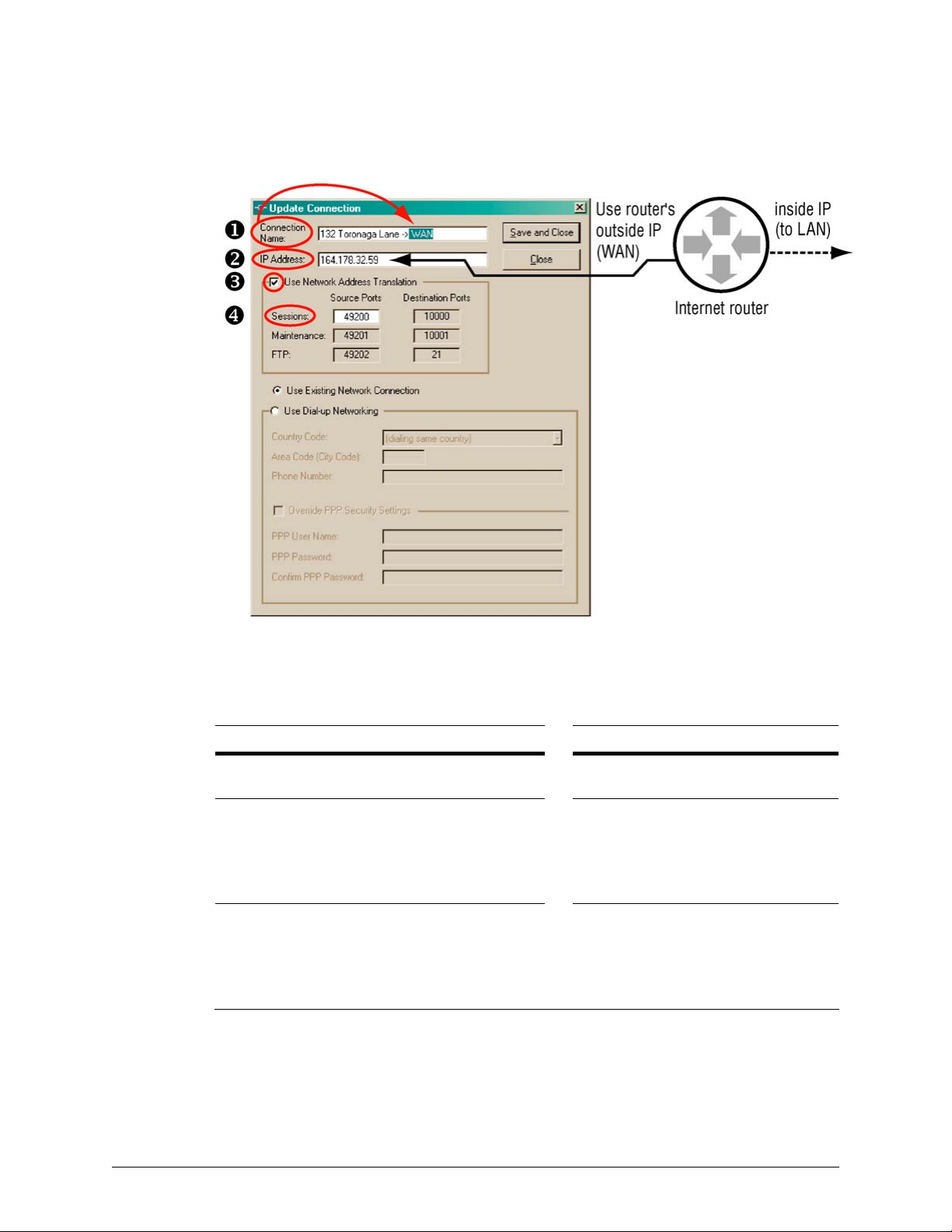
Multi-Media Site: Connection Configuration
Setting a Router’s Mappings
Fig. 3–10. NAT Configuration: Router Settings.
Supply the three destination ports for Multi-Media unit to the network administrator of the router.
Indicate that they need to be mapped to the Outside IP Source Ports on the router, and to the
unit’s LAN IP Address. See table
Table 3–5 Router Mappings: Example for Operation of Multi-Media Units
Admin settings to: destination Network device: mappings
NAT Port
(to network device)
unit “A”
Session: 49,200* 164.178.32.59 > 10,000 192.168.101.2
Maintenance: 49,201 as above > 10,001 map as above
FTP: 49,202 as above > 21 map as above
unit “B”
Base: 49,300* same IP as above > 10,000 192.168.101.3
Maintenance: 49,301 as above > 10,001 map as above
FTP: 49,302 as above > 21 map as above
* Values are arbitrary. Consult the network administrator for appropriate NAT port values.
3–5, below, or figures 3–8 and 3–10.
Device’s Outside IP
(constant)
Physical Port
(firewall & unit)
Inside IP
(unit’s address)
40
Page 41

Updating a Unit's Connection
1. Using Admin software, add (or update) a connection to a site. You have the option of
renaming the suffix in the connection name to “WAN”, “Internet” or other useful reminder
of what type of connection is being set up. See figure 3–10.
2. Assign the router’s outside IP address to the IP Address box.
3. Enable Use Network Address Translation.
System Administrator’s Guide
4. Assign a value to the NAT Sessions Source Port. In figure
Sessions has been changed from 10,000 (the default) to 49,200. A value greater than
65,533 cannot be used.
5. Click Save and Close. To access the unit using View software, see
Multi-Media Local Db.
Refreshing the Multi-Media Local Db
Operators connected to the Multi Central database can either:
• If View is running, click Refresh.
• If View is not running, run View.
For operators that are not connected to the Multi Central database, your organization's Multi SA
needs to supply each of them with an updated Local database. See
242.
on p.
Dynamic Host Configuration Protocol
Flexibility
Multi-Media units support the Dynamic Host Configuration Protocol (DHCP). By default, MultiMedia units are not clients of DHCP.
3–10, for example, the value of
Refreshing the
Producing a Local Database,
Network administrator needs for using DHCP with DNS
The DNS registration of DHCP leases is made with the DNS specified by the DHCP server, network
card properties. Contact your organization's Network administrator to obtain the proper primary
DNS entry for your local client if the name is not resolved.
To Configure DHCP Using Microsoft’s Server2000 (or 2003)
1. Using the DHCP MMC, open the local DHCP Server Properties window.
2. On the DNS (Dynamic Network Service) tab, select Always update DNS.
3. Add a checkmark to the box next to Enable updates for DNS clients that do not support
dynamic update.
4. Restart the DHCP service.
Document K14392V1 Rev A 41
07/07
Page 42

Multi-Media Site: Connection Configuration
Choosing the Computer Name or a Static IP
In the IP Address box
With DHCP, your network administrator has the option of assigning either a dynamic IP address or
static IP address to a Multi-Media unit. See the procedure:
Either a dynamic IP address or computer name. For units on a DHCP-enabled network,
registration of DHCP leases is made with the DNS specified on the Properties of the network card
in the DHCP server. If the name is not resolved, contact the Network administrator to obtain the
proper primary DNS entry for your local client. When performing procedure
Connection, on p.
definition (instead of an IP address). A computer name for a Multi-Media unit is:
“REM[hyphen][site serial number (without leading zeroes)]”;
for example: REM–7654321.
The unit’s serial number is printed on a sticker affixed to the unit and may contain leading zeroes.
Static IP address. Within DHCP, your network administrator has the option of reserving an IP
address after it has been assigned to a Multi-Media unit. The Multi SA types this address in the
IP Address box of a Multi site’s definition, instead of a unit’s computer name. If for some reasons it
is not practical to match the DNS entries, it is then preferable to use the local hosts or lmhosts file
to match a reserved DHCP loaned IP with a multi NetBIOS name. The IP needs to be reserved in
the DHCP server by the network administrator for using the hosts or lmhosts file.
35, a Multi SA types a computer name in the IP Address box of a Multi site’s
To Set a Network Connection, on p. 35.
To Set a Network
Within DHCP without DNS, an assigned IP address needs to be reserved or it will change.
Let the network’s administrator as well as the Multi SA know of the unit’s installation; as a
unit is reset, a new DHCP address is assigned to it and communication to the unit could be
hampered if configured incorrectly.
Network without DHCP
If DHCP is unavailable on your network, a unit’s request for DHCP services times-out after two
minutes.
More about DHCP
Further discussion of DHCP is beyond the scope of this
personnel for information about DHCP.
System Administrator’s Guide. Consult IT
42
Page 43

Many Connections to a Unit
Depending on your organization’s needs, you can have one or many types of connections. There
can be a mix of network and dial-up connections. A dial-up connection can be simultaneous with
many network connections.
Fig. 3–11. Operating a Unit through Many Connections.
System Administrator’s Guide
Tip
Setting up many connections is optional.
For other means of connecting to a Multi-Media unit, see table 3–1 on p. 29.
To Specify Dial-up and Network Connections
Using the “Update Site” dialog box (or “Add site” dialog box), you can set as many connections as
needed.
• For a dial-up connection, see p.
• For a network connection, see p. 34.
The connections are listed in the Update Site dialog box. See figure
The primary connection
You can change the order by dragging an item to a different place in the list. The connection that
you list first, is the primary connection. The primary connection can be either network or dial-up.
30.
3–12, on p. 44.
Document K14392V1 Rev A 43
07/07
Page 44

Multi-Media Site: Connection Configuration
Fig. 3–12. Listing of Connections (Two) to a Site.
RAS Server
There are two ways of connecting to Multi-Media units when using a Remote Access Service (RAS)
server.
• Only one RAS-dependent unit at a time. A RAS server can be transparent to users of View by
adding RAS server information to the site definition. This is ideal when there is only one MultiMedia unit on the network using the RAS server. See figure
• Many units at once. Users dial-up the RAS server before using View. This is discussed later in
Using a RAS Server before Connecting to a Unit on p. 47.
For both cases, a RAS is set up on a server that can access networked Rapid Eye Multi-Media
units.
Tip
A RAS connection is optional. For other means of connecting to a Multi-Media unit, see
table 3–1 on p. 29.
3–13.
Planning to Connect to One Unit at a Time
You can use View to automatically connect to the site. A user has to end sessions with the unit
before using another unit on that same network. From a security point of view, the View operator
does not need to know the RAS username and password.
44
Page 45
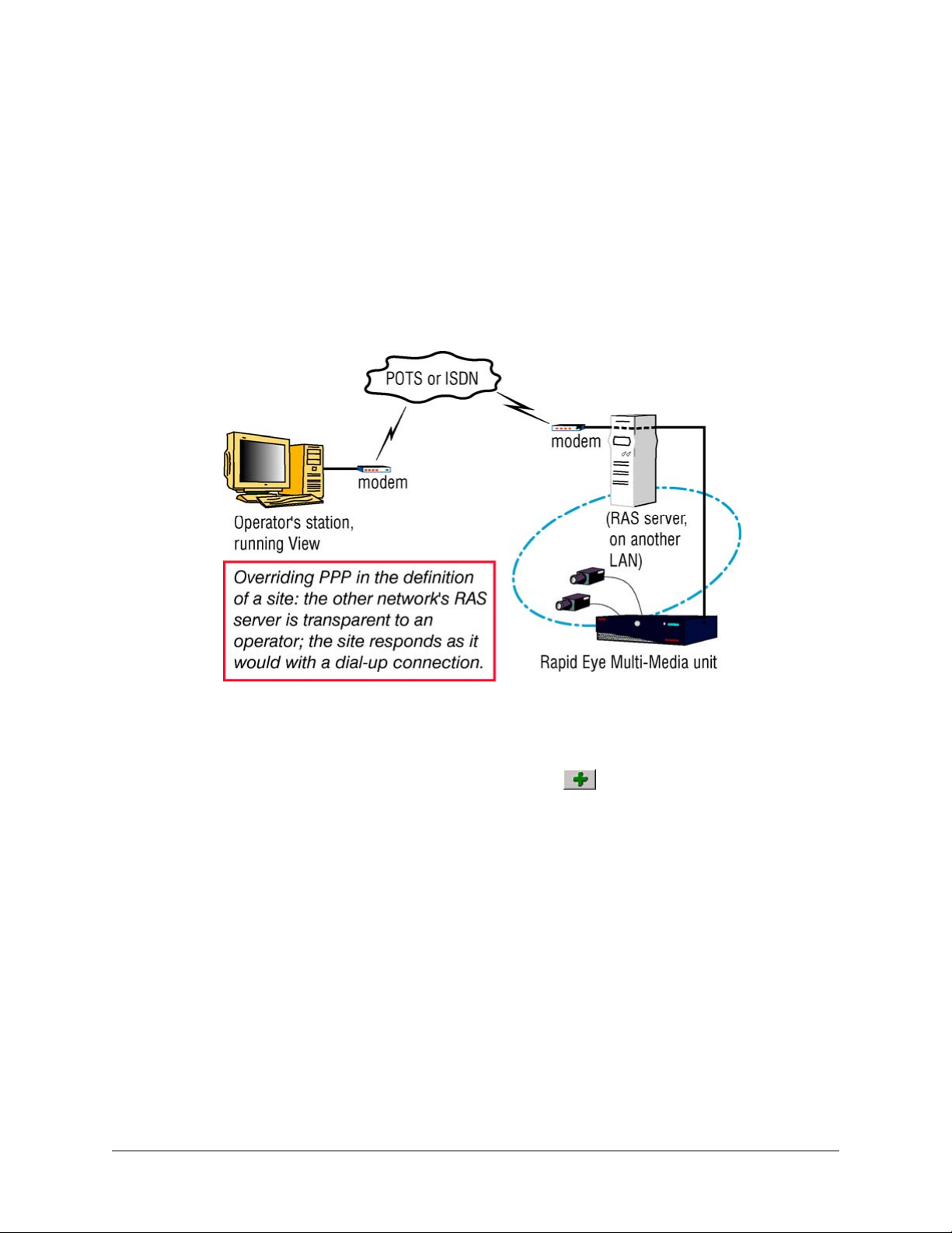
System Administrator’s Guide
A connection that behaves like dial-up
A session request behaves just as if you had reached the site’s Multi-Media unit by connecting
directly to it, by dial-up. Such a connection behaves as if it were a simple dial-up; two dial-up sites
cannot be used at the same time with one modem. Sessions to a dial-up site have to be closed
before using another dial-up site.
What your network administrator needs
Multi sessions (live, retrieval and alarm) are sent to port 10,000. This port should be left open in
your organization’s firewall, for the sockets used by Multi.
Fig. 3–13. Connecting to a Rapid Eye Site through a RAS Server, Transparently.
To Set a Connection to a RAS
1. In the Add Site/Update Site dialog box, click in the “Connections to the Site” pane.
The Add Connection dialog box appears; see figure
the Connection Name box appends a stylized arrow and “Network” suffix to the site’s
name; this suffix may change as the next steps are carried out. Note that the suffix is not
changed when updating a connection.
2. In the IP Address box, type the Multi-Media unit’s IP address, obtained from your
network administrator, as mentioned in section
3. Click Use Dial-up Networking. The connection’s suffix changes to “dial-up”.
4. As needed, change or leave the Country Code used to reach the RAS server by
telephone.
5. Type the RAS server’s Area Code (City Code) and Phone Number obtained from your
network administrator (also mentioned in
Tip
If your telephone exchange needs a prefix number (an extra telephone key stroke such as a
“9” or an “8”) to access an outside line: Set this in the Window's Telephony program used
by the PC. For local calls that span area codes or long distance calls within one area code,
Area Code: Irregular Use, above.
see
3–14. When adding a connection,
Naming / Renaming a Site.
Naming / Renaming a Site).
Document K14392V1 Rev A 45
07/07
Page 46
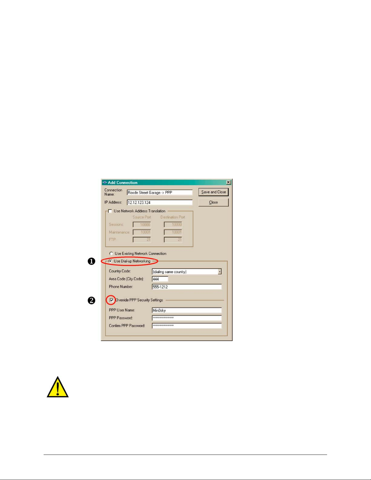
Multi-Media Site: Connection Configuration
6. Select the Override PPP Settings checkbox. See figure
added, a “PPP” is appended to the connection name. You have the option of either:
• Typing another name in the Connection Name box, such as adding "RAS".
- or -
• Leaving the connection name in the Connection Name box as it was
automatically set by Admin.
7. Enter the PPP user name and password; these are obtained from the network
administrator responsible for the network’s RAS server.
8. Type the PPP password a second time.
9. Click Save and Close. The “Add/Update Connection” window appears.
10. Click Close. The Sites tab appears In the tab’s Primary Connection column, the first
letter of PPP appears in parentheses: (p), followed by the telephone number to connect
to a RAS server; then by (n) and the IP address used to connect to the Multi-Media unit.
See also figure
Fig. 3–14. RAS Server's Telephone Number and PPP Information.
3–6, p. 35.
3–14. If a connection is being
46
Tip
A Multi-Media unit’s own dial-up PPP username and password is used by default. Entering
a PPP username and password in a site’s definition makes View use your entries for PPP
instead of the Multi-Media unit’s during a dial-up connection.
Technical warning for PPP: Changing the “Rapid Eye Multi” phone book entry in a dial-up
program is ineffective. The phonebook entry is overwritten by data in the Multi database
every time an automatic connection to a RAS server is attempted.
Page 47
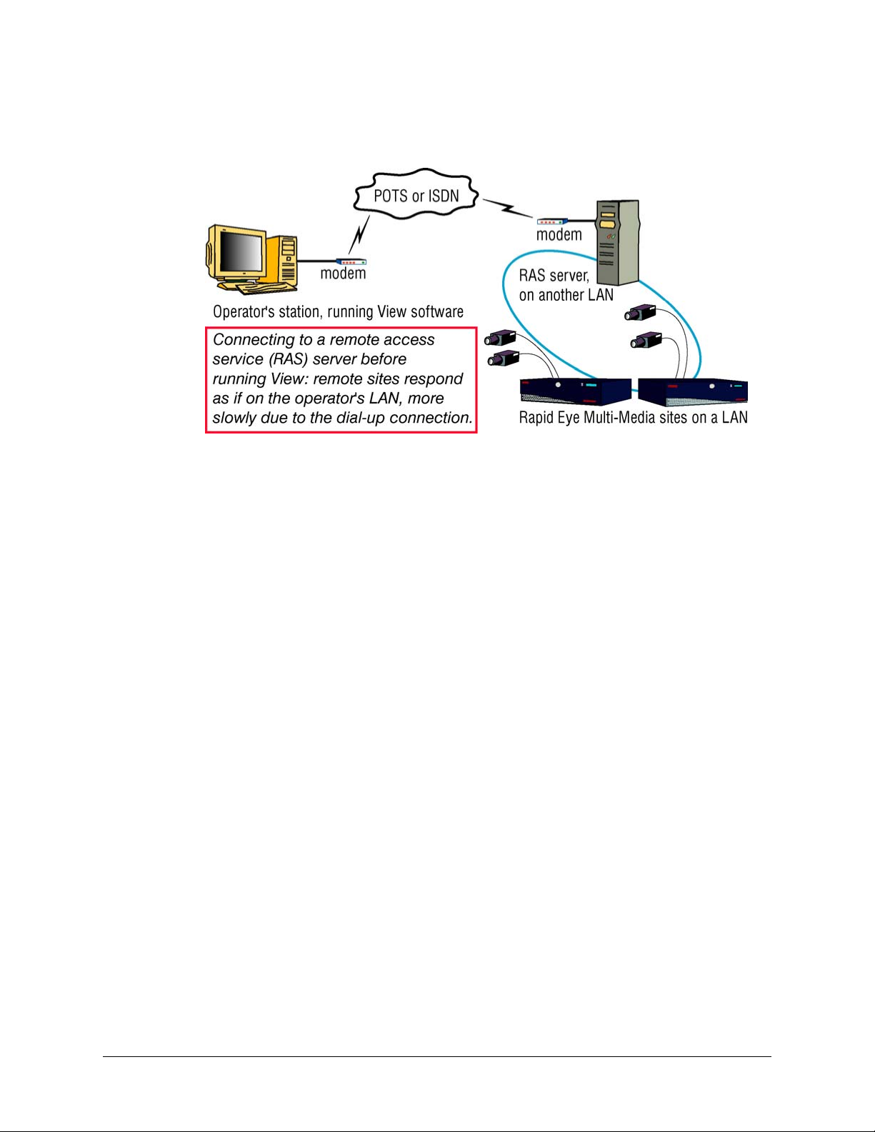
System Administrator’s Guide
Using a RAS Server before Connecting to a Unit
Fig. 3–15. Connecting to a RAS Server, Before Running View to Operate Units.
Tip
A RAS server may not be needed by your organization.
For other connections, see table 3–1 on p. 29.
The two ways of using dial-up to connect to a Remote Access Service (RAS) server are:
• Many units at once. A View operator, using a dial-up program of his/her choice, dials-up the
RAS server before using View. The definitions of Rapid Eye sites do not contain RAS or PPP
information. The sites are meant to behave as if they were on a View operator’s LAN. See
3–15.
figure
• Only one RAS-dependent unit at a time. See
In both cases, a RAS server has been set up on a server that accesses Rapid Eye Multi-Media
unit(s) on a network.
Planning to connect to many units
For access to a RAS server “in front of” Rapid Eye sites on a network, the RAS server’s information
is not recorded in the Multi-Media sites’ definitions. The RAS information must be known by the
user of the PC and recorded in a Microsoft dial-up application. The user must use the dial-up utility
to connect to the RAS server before starting a session at the site, using View.
Preparation
Use the information in section
using Admin. You can then use a modem to connect to these sites using the Microsoft dial-up
application to connect to the RAS server.
Using Network Access, on p. 34 to define the sites as network units,
RAS Server, p. 44.
Use of an outside line requiring a prefix number
A prefix is an extra telephone keystroke such as a “9” or an “8” that you should be set in the
Window's Telephony program, running on the PC.
What your network administrator needs
Multi sessions (live, retrieval and alarm) are sent to port 10,000. This port should be left open in
your organization’s firewall, for the sockets used by Multi.
Document K14392V1 Rev A 47
07/07
Page 48

Multi-Media Site: Connection Configuration
Connections: Report and Customization
A site’s connections are listed on the “Update Site” window. To view connections in the “Update
Site” window:
1. Using Admin, click the Sites tab.
2. On the list of sites, do one of the following:
• Double-click the site name you want to view.
• Right-click a site name and click Update on the menu that appears.
• Click a site name; then either: click on the toolbar, click Update on the
Actions menu or press the F12 key.
Connection codes
The codes used to identify connections are listed in table
Table 3–6 Automatic Connection Names for a Rapid Eye Site
Site Tab’s Report Automatic Name Connection
(n) IP address Garage -> Network network
(d) telephone number Garage -> Dial-up dial-up
(p) telephone number (n) IP address Garage -> PPP dial-up to RAS
(d) telephone number Garage -> Dial-up 2 second dial-up
3–6, in the “Site Tab’s Report” column.
The Automatic Naming of Connections
About Admin’s naming convention for connections
Only when adding a site does Admin automatically name a connection in the Connection Name
box. Admin uses the site’s name, appends a stylized arrow and adds the connection type. See the
“Garage” example used in table
3–6.
Changing the Automatic Suffix in a Connection's Name
48
Tip
You can always rename a connection in full or partially, by typing in the Connection Name box.
1. While adding a site (as in
in the “Connections to the Site” pane. The Add Connection dialog box appears. The
Connection Name box appends a stylized arrow and “Network” to the site’s name.
2. Admin automatically names the connection in the Connection Name box. You have the
option of keeping the name or of typing another.
3. An “Add Site / Update Site” window is displayed.
4. Click Close. The Sites tab appears.
When updating a connection, its name is not changed. You have the option of changing it.
Naming / Renaming a Site, above) or updating one, click
Page 49

Firewall: Technical Note
Multi sessions (live, retrieval and alarm) are sent to port 10 000, by default.
Table 3–7 Default Transmission Control Protocol (TCP) Ports
Port* Name Use Needed at …
10 000† Base live, retrieval and alarm sessions Multi-Media unit
10 001 Maintenance Maintenance Session for configuration,
security, and sending/receiving system files
21 FTP file transfer during upgrades and to obtain a
unit’s log
10 003 Alarm alarm server for callbacks alarm station
* These port settings are listed in the Add Connection/Update Connection dialog boxes.
† The base port can be changed by using Admin software. For an example, see Network Address
Translation.
The TCP ports listed in table 3–7 should be left open in your organization’s firewall.
System Administrator’s Guide
operator station
Multi-Media unit
administrator’s station
Multi-Media unit
administrator’s station
Multi-Media unit
Cascading Alarm Stations
Flexibility in security
Prioritizing alarm stations is optional and applies only if many Multi alarm stations were created by
your organization's Multi SA.
Purpose: cascading and priority
Your Multi system can have one or many alarm stations. With many, cascading is automatic and
customizable. You can specify which alarm stations your Multi-Media units tries to reach first.
Cascade sequence
To insure against alarm station unavailability, you can:
• Assign more than one alarm station to a unit
• Set the order in which alarm stations are called.
Preparations
Before you prioritize alarm stations:
• Create Alarm stations using the Alarm Station tab. See
Reports, p.
• Set events to trigger alarms. An alarm station is ineffective until events are set to trigger alarms.
See
Document K14392V1 Rev A 49
07/07
203.
Events Defined, on p. 187.
Adding an Alarm Station: Name and
Page 50

Multi-Media Site: Connection Configuration
To Sequence a Site’s Alarm Stations
1. While Naming / Renaming a Site, p. 24, the alarm station(s) that the site can call are
listed. The list is in the Report Alarms to these Alarm Stations pane of the “Add Site” or
“Update Site” window.
2. To change the order of an alarm station, drag its name
to the position that you want it to have in the list.
3. End the edit of the site definition. To do so, click Save and Close. The Admin window
reappears, listing your system’s sites on the Site tab.
4. Use View to update security for the Multi-Media unit. See
Media Unit, on p.
131.
Updating Security on a Multi-
Quickly Assigning a Site to Many Alarm Stations
Using the Update Site windows
The Update Site window can be used as a shortcut to add a site to many alarm stations.
Alternatively, each Multi Alarm Station can be opened and a site added to each, as explained in
Adding an Alarm Station: Name and Reports, on p. 203.
1. Using Admin, click the Sites tab.
2. While Naming / Renaming a Site, p. 24, click in the “Report Alarms to these
Alarms Stations” pane. The Add/Delete Stations to Call in Case of Alarms dialog box
appears, displaying a list of alarm stations created on the Alarm Station tab. Stations
already assigned to the site that you are editing are listed the Report Alarms to column.
3. Select one or many station names in the Alarm Stations available column.
4. To move the station names to the Report Alarms to column, either:
• Click the right-arrow, or
• Double-click the ones that you want to move.
5. Click Save and Close. The Add Site/Update Site dialog box reappears, listing the
names of the alarm stations in the Report Alarms… pane. The site is also added to the
site list of each alarm station that you have assigned.
6. You have the option of ending the site edit. To do so, click Save and Close. The Admin
window reappears, listing your system’s sites on the Site tab.
7. You need to use View to update security for the Multi-Media unit. See
on a Multi-Media Unit, on p.
131
Updating Security
Setting a Site to Not Report Alarms to a Specific Station
1. Using Admin, click the Sites tab.
2. While
Naming / Renaming a Site, p. 24, click in the “Report Alarms to these
Alarms Stations” pane. The Add/Delete Stations to Call in Case of Alarms dialog box
appears, displaying a list of alarm stations. Stations already assigned to the site are
listed the Report Alarms to column.
50
Page 51

System Administrator’s Guide
3. To move alarm station names to the Alarm Stations available column, either:
• Select one or many station names in the Report Alarms to column; then click the
left-arrow, or
• Double-click the ones that you want to move.
4. Click Save and Close. The Add Site/Update Site dialog box reappears, listing the alarm
stations in the Report Alarms… pane.
5. You have the option of ending the site edit. To do so, click Save and Close. The Admin
window reappears, listing your system’s sites on the Site tab.
6. You need to use View to update security for the Multi-Media unit. See
on a Multi-Media Unit, on p.
131
Updating Security
Customizing a Dial-Up Connection to an Alarm Station
The Multi SA may need to customize the telephone number used to reach a Multi-Media Alarm
Station.
Fig. 3–16. For Local Call s that Need an Area Code, Customize Dial-up.
Preparation
An alarm station’s telephone number in the site definition is a copy of the number in the alarm
station definition. Before customizing a dial-up connection, consider if the alarm station definition
is correct, as explained in
Dial-Up Connection to an Alarm Station, p.
Document K14392V1 Rev A 51
07/07
Dial-up Connection to an Alarm Station on p. 208, and Customizing a
211.
Page 52

Multi-Media Site: Connection Configuration
To Customize the Dial-up Connection to an Alarm Station
Fig. 3–17. Customizing an Alarm Station’s Telephone Number.
1. While creating or updating a site, select an alarm station.
2. In the Report Alarms to these Alarm Stations pane, click
Update Station to Call in Case of Alarms dialog box appears.
3. Modify the telephone number so that it is as one would dial it. You have the option of:
• Removing/adding long distance country and area codes, or
• Typing a prefix and commas, as needed to dial-out of a site’s exchange.
4. Click Save and Close. The modified telephone number appears in the Connection
Method column in the Report Alarms to these Alarm Stations pane. An asterisk is added
in parenthesis (*) to the entry’s display, to indicate customization.
5. Update security for the unit; see
Updating Security on a Multi-Media Unit, p. 131.
. See fig. 3–17. The
To Cancel the Customization of a Telephone Number
1. While creating or updating a site, an alarm station with a customized telephone number
shows an asterisk (*) in the entry’s display.
2. In the Report Alarms to these Alarm Stations pane, click . The Update Station to
Call in Case of Alarms dialog box appears. See fig.
3. Click Default in the Update Station to Call in Case of Alarms dialog box. The telephone
number returns to the one entered in the Alarm Station definition.
4. Update security for the unit; see Updating Security on a Multi-Media Unit, on p. 131.
3–17.
52
Page 53

Unit Configuration: Basics
Maintenance Session
Using View
4
View software is used to run a
software. The Maintenance Session is discussed in this System Administrator’s Guide because the
session is designed to be used by the system administrator (the Multi SA) designated by your
organization, to maintain and supervise your Rapid Eye System.
Using a Maintenance Session
The Maintenance Session is used to configure:
• System hardware.
connected to the unit.
• Security.
Security on a Multi-Media Unit, on p.
Scope of a Maintenance Session
A Maintenance Session involves only the unit on which it runs. You can use View software to open
a Maintenance Session on more than one unit at a time. Two operators cannot each run a
Maintenance Session on the same unit. While a Maintenance Session runs, the unit’s LocalView
interface continues to display video but is unavailable for unit operation.
A Maintenance Session is also used to:
• Make a site operational. Running a Maintenance Session is needed before operators can start
using a Multi-Media site; see
• Obtain a unit’s statistics. See
Events Defined that trigger alarms and other security settings. See also Updating
Cameras, Multi Audio, motion detection, scheduling, and other hardware
Maintenance Session on a Rapid Eye Multi-Media unit, not Admin
131.
Making a Site Operational, p. 55.
Hardware Report, p. 140 and To Obtain a Unit’s Statistics, p. 128.
Document K14392V1 Rev A 53
07/07
Page 54

Unit Configuration: Basics
To Start a Maintenance Session
1. Log on to View, using a central database.
2. Using View, select a site on the Sites list, for which maintenance must be performed.
3. To start a Maintenance Session, either:
• Right-click on the site name to select [Maintenance] from the shortcut menu.
• Select the site; then click the Maintenance command on the Actions menu.
• Select the site; then click
4. If the Connections dialog box appears, choose the network/dial-up connection that you
need and click OK. The maintenance tabs appear.
5. Wait for the “System Operational” message in the Feedback box.
Site feedback
During maintenance, messages about the session appear in the Feedback box. For a list of the
messages, see
Reboot button in Maintenance window
The Reboot button reboots the Multi-Media unit, not your PC.
Technical note for network administrators
For connections over a network, Multi
port open in your organization’s firewall, for sockets used by Multi. For other ports used by Multi
on a network, see table
Feedback Box Reference, on p. 64.
Maintenance Sessions are sent to port 10,001. Leave this
3–7 on p. 49, in System Tab in a Maintenance Session.
Support for Older Models of Units
on the toolbar.
54
Setup and Maintenance
Older-model, Rapid Eye units are supported. If an older unit lacks a newer feature, the feature is
not shown in a
for older units. For example, a Recording tab does not appear when running a Maintenance
Session on an older-model unit; instead, the Video tab is used for the settings of recorded video.
Using older documentation
For the setup and operation of older-model units, Honeywell recommends referring to the user
guides that came with those units, as needed. Adobe PDF files of these older guides are available
from Honeywell, on its website at
Maintenance Session. The interface appears as it did in the last-available upgrade
www.honeywellvideo.com.
Page 55
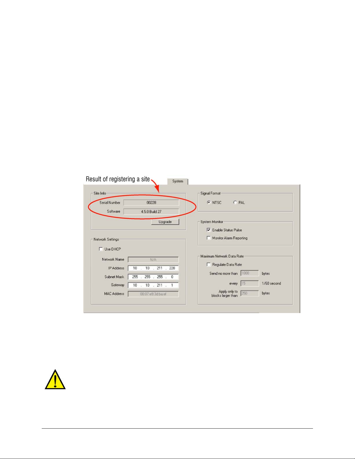
Making a Site Operational
A Multi-Media unit is “working” within minutes of being turned on. There are a few crucial steps
needed to make your Rapid Eye site an outstanding security tool.
The first Maintenance Session
You run the first Maintenance Session at a site after:
System Administrator’s Guide
• Adding that site to a Multi central database. See
• Upgrading a Multi unit.
Site registration
When the first Maintenance Session runs, the validity of the communication data to the site can be
checked. If correct, the site is registered automatically, making it available to View operators who
have the right to use it.
Fig. 4–1. Multi-Media Unit Serial Number and Version of Unit Software.
Naming / Renaming a Site on p. 24
The Multi-Media unit has a serial number and software version. These numbers are displayed on
4–1, and on the Hardware tab.
Tip
the System tab, as illustrated in fig.
Someone has to run a Maintenance Session on a unit before he or any other View operator
can run Live Sessions.
One Maintenance Session is enough to register a site for all users of that site.
Honeywell recommends setting a unit to the correct time zone, time and date before using
the unit in your organization's operations.
Document K14392V1 Rev A 55
07/07
Page 56

Unit Configuration: Basics
Security considerations
A Multi-Media unit is “working” within minutes of being turned on, however there are crucial steps
to make your Rapid Eye site a useful security tool:
• Set the time zone and time. See
can make the identification of video impossible.
• Check the camera configuration. See
you need to specify drivers for cameras that pan, tilt or zoom (PTZ).
• Test the alarms. For events set to trigger alarms, test if these events give you the anticipated
results. See
• Honeywell recommends using a system password. Without a system password, your Rapid Eye
sites can be accessed by Admin users in other organizations. To avoid this situation, see
Securing a Site, below.
Scheduling options
By default, video is recorded all the time and alarms can be triggered at any time. You have the
option of having cameras and alarms disabled on days and at times of your choice. To do so, see:
Scheduling: Configuration, p. 105.
Events Defined, on p. 187.
Unit’s Time Zone and Clock, on p. 56. Incorrect time stamps
Unit’s Time Zone and Clock
Crucial settings for reporting on video of events
Setting the Time Zone and System Clock on Multi-Media units is crucial to the correct identification
of video. These settings also govern the scheduled recording and scheduled alarm features.
Please set them with care.
Cameras, on p. 65. Cameras are detected automatically;
Fig. 4–2. Unit Time Using SNTP as a Reference.
56
Page 57

System Administrator’s Guide
Time zone
Your Multi SA needs to indicate in which time zone each Multi-Media unit is installed. Make this
setting whether a Multi-Media unit’s clock is set manually or automatically.
The Time Zone of a unit is crucial for correctly reporting on the video of events.
To Indicate the Time Zone of a Multi-Media Unit
1. Using View, select a unit whose time zone needs to be set.
Tip
2. Start a
3. Click the Time tab. See figure
4. If the zone indicated in the Time Zone box is incorrect, click the arrow in the box. A list of
5. Scroll the list as needed to find a match for the time zone in which the unit is installed. The
The time zone is set on a unit-by-unit basis. Repeat this procedure for every unit in your
system.
Table 4–1 Effect of Time Zone Setting on Display and Clips
Operator’s PC* Unit’s Time Zone
showing: 4 PM
Eastern Time
showing: 4 PM
Eastern Time
* To set the time zone on an operator’s PC, use the Control Panel in Microsoft Windows. See also
the Rapid Eye View Software Operator Guide: Selecting a Time Reference.
† Set using View, while running a
‡ Display can be changed for a session’s duration to LTZ (the local time zone set on your PC),
RTZ (a camera’s remote time zone) or to UTC (universal time zone). See the
Software Operator Guide.
Maintenance Session.
4–2.
all time zones appears.
time zone is set right away; there is no need to reboot the unit.
†
Time Shown‡: Sessions & Clips
Eastern Time
UTC – 05:00
Pacific Time
UTC – 08:00
Maintenance Session.
show unit’s time and recorded video
as 4 PM
show unit’s time and recorded video
as 1 PM
Rapid Eye View
Conflicting Time Zones
A Multi-Media unit’s time zone can be changed without the knowledge of a View operator. It can
be done at the unit, using LocalView, or through another Multi-Media database (Multi db). The
View operator’s next attempt to access the site is interrupted by a message, shown in figure
The message also appears for areas within a time zone that have different rules for daylight
savings time. For example: “Indiana (East)” in the Eastern time zone (GMT-5:00) differs from
“Eastern Time (US Canada)”, also GMT-5:00. To respond to a notification of conflicting time
zones, select the time zone that indicates where the Multi-Media unit is installed and then click OK.
Document K14392V1 Rev A 57
07/07
4–3.
Page 58
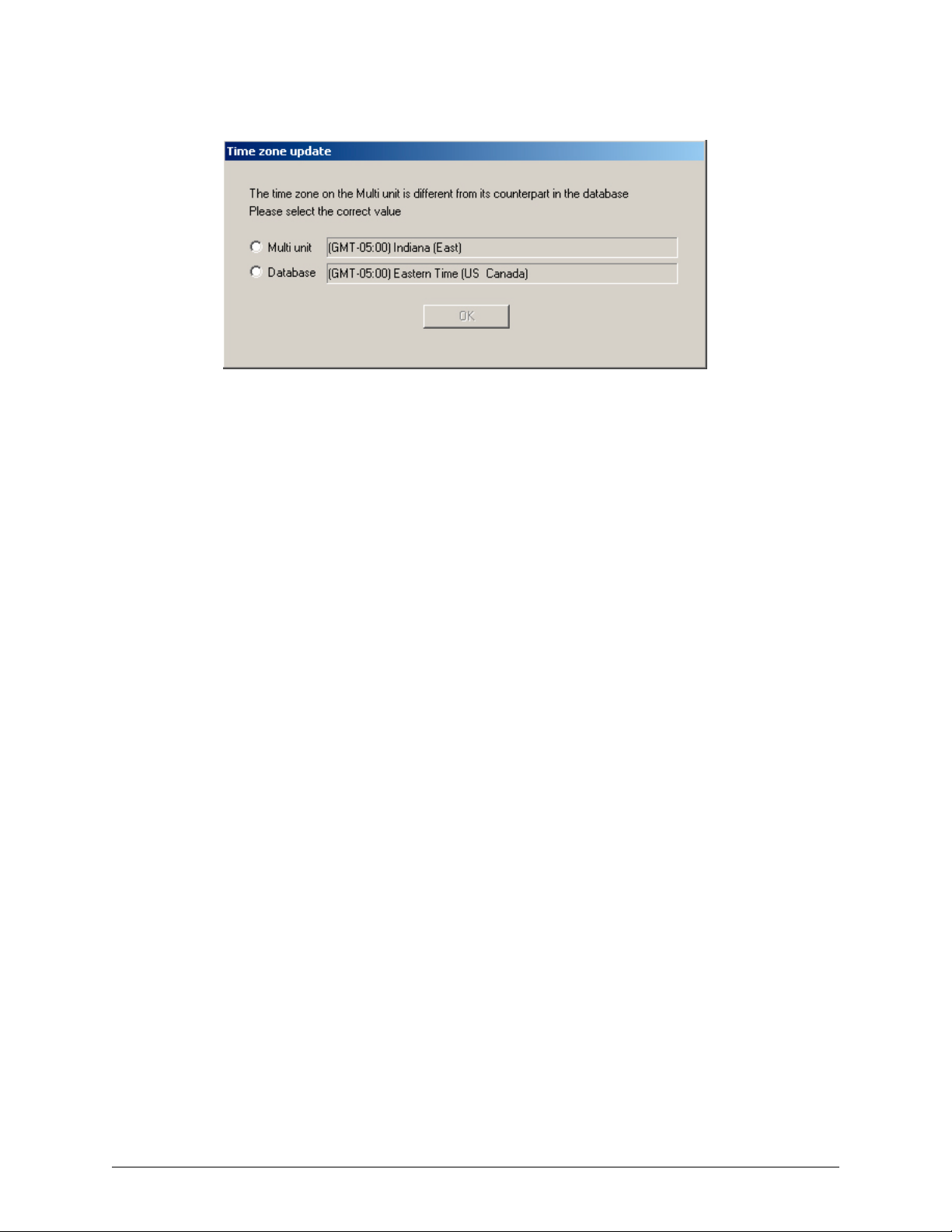
Unit Configuration: Basics
Fig. 4–3. Different Rules May Apply for Daylight Savings Time in one Time Zone.
SNTP: Setting the Clock Automatically
See your IT Administrator to find out if a Simple Network Time Protocol (SNTP) server is in use.
Multi-Media units on a LAN can benefit from the automatic setting. It is accurate to within a fraction
of a second.
1. Obtain the IP address of an SNTP server. You have the option of also obtaining the
address of an alternate server.
2. Using View, select a unit whose clock needs to be set.
3. Start a
4. Click the Time tab.
5. If Automatic is not selected, click it. The Time tab appears as in figure
6. Click the Primary SNTP Server box and type the IP address of an SNTP server obtained
7. Click Refresh. The Multi-Media unit contacts the SNTP server and synchronizes the Multi
8. You have the option of ending the maintenance; see
Auto-synch statistics
The statistics appear are for
Auto-synch statistics do not apply to a clock set to Manual.
Last Synchronized at. Latest time that the SNTP server was used. Synchronization to SNTP occurs
at least every 24 hours.
Time Difference. Accuracy of synchronization.
Maintenance Session.
4–2.
in step 1. You have the option of indicating an alternate in the Alternate SNTP Server
box.
clock to the SNTP time.
Ending Maintenance, p. 62.
Multi technical support, if they make a service call to your site. The
58
Page 59

System Clock: Manual Setting
A Multi SA can synchronize the clock of a Rapid Eye Multi-Media unit using a PC’s clock as
reference. This is more useful for units connected only by dial-up, but can also be used for units
on a LAN.
System Administrator’s Guide
Tip
Check/set the clock on an operator's PC, before setting a unit's clock manually.
Adjusting the Clock on a PC Running Rapid Eye Software
To adjust a PC’s time, date and time zone, click Start followed by Settings, Control Panel and
Date/Time. Check the accuracy of the time and the time zone on the PC and adjust it as needed.
Using a PC’s Clock to Set a Unit’s Clock Manually
1. Using View software, select a Multi-Media unit whose clock needs to be set.
2. Start a
3. Click the Time tab. If Manual is not selected, click it. The Time tab appears as in figure
4. Click Set Multi-Media Unit’s Clock.
Fig. 4–4. Setting a Multi-Media Unit’s Clock Manually.
Maintenance Session.
4–4.
Synchronizing time over dial-up
Due to the nature of dial-up connections, the Multi-Media unit’s time may still be off by a few
seconds after synchronizing time.
Document K14392V1 Rev A 59
07/07
Page 60

Unit Configuration: Basics
Adjusting the Time on an Operational Unit
If a unit's clock is set incorrectly (more than +/– a few seconds), Honeywell recommends
setting a unit to the correct time (and date) as soon as possible.
Human error or unauthorized use
Leaving the clock set to an incorrect time (more than +/– a few seconds) for a long length of time
(an hour or more) on an operational unit, can create problems for operators who need to retrieve
video when the clock is set correctly.
During the 'span of incorrect time', video is not erased and continues to be recorded; however, two
instances of video can be created at the same timestamps. Using the Seek or Jump controls
shows the video of the first instance only. The second instance of video can only be played
through or fast-forwarded.
Correcting the Clock
Whole hours: time reference
Check the "Time Reference" setting. If the clock of a unit in another time zone shows a time that is
off by whole hours, the clock could be set to the correct time, but using an optional display (GMT,
operator's time zone, unit's time zone). See the
a Time Reference.
Whole hours: time zone
Check the "Time Zone" setting. If the clock of a unit in another time zone shows a time that is off by
whole hours, the clock could be set to the correct time, but set to an incorrect time zone. See
Unit’s Time Zone and Clock, p. 56.
Setting the clock to the correct time
A short span of incorrect time. If a unit's clock shows the wrong time (more than +/– a few
seconds), for a short while (a few seconds, a few minutes, up to an hour, or so):
• Set the clock correctly; either automatically or manually.
A follow-up may be needed: clearing storage
A long span of incorrect time. If the clock remains set to an incorrect time (more than +/– a few
seconds) for a considerable length of time (many hours, days or weeks) it can become
inconvenient and confusing for an operator who needs to play through that recorded video. For
such an error:
• Set the clock correctly; either automatically or manually.
• Consider
Clearing Storage. See p. 129.
Rapid Eye View Software Operator Guide: Selecting
60
Page 61

Securing a Site
Securing the Multi system
Making a Site Operational (see p. 55), Honeywell recommends that you secure your Rapid
After
Eye site by adding:
• A system password. Use Admin to set a system password to protect your sites from
unauthorized accounts. See
- and -
• A password for the “Administrator” account. To help prevent: (a) an uncontrolled configuration
of Multi-Media units; (b) the accidental clearing of a unit’s storage or (c) unwanted removal of
the system password. See
Then update security, as explained in Updating Security on a Multi-Media Unit, on p. 131.
Rebooting a Unit
1. Start a Maintenance Session for the Rapid Eye site. Please wait until the “System
operational” message appears.
2. Click Reboot.
System Administrator’s Guide
System Password, on p. 166.
Administrator Password, on p. 176
Lack of reasons to reboot a Multi-Media unit
Use of the Reboot button does not damage the unit. It does however interrupt the recording of
video for a few moments and should best be left alone, unless
operator to click it. A reboot can be traced to the operator who performed it. See Tracing Events
191.
on p.
The button is for rebooting a Multi-Media unit. Do not mistakenly reboot your PC when
called to “click the Reboot button in the Maintenance window”.
Multi technical support instructs an
Automatic reboot of Multi-Media unit
A Multi-Media unit reboots by itself when:
• Changes to a modem serial device are applied. Modem settings are explained in section
Device: Modem, on p.
• System files are upgraded; as explained in
- and -
• Power to the unit is interrupted and restored.
138
System Files, p. 132.
Serial
Document K14392V1 Rev A 61
07/07
Page 62

Unit Configuration: Basics
Maintenance Reference
Ending Maintenance
To end a Maintenance Session, close the Maintenance window.
Other actions can also close sessions:
• Click
• Click Disconnect on the Actions menu
• Close View.
Using Apply
The Apply button is used after changes have been made to the: IP address and other network
settings (including DHCP), motion mask, or response rules. If the Apply button is active and you
click another tab, the button remains active.
Maintenance Topics
Table 4–2 Maintenance Reference Topics
Topic (alphabetically) Important for … Action See… (page)
Cameras video configuration 65
Clearing Storage video archive action 129
Customer Data and Customer-Device
Events
Dial-up Connection: to a Unit dial-up action 30
Events Defined alarms action 187 & 149
Feedback Box Reference system files report 64
Hardware Report Honeywell report 140
Public Display Monitor: Using Monitor
Output 1
Motion Detection motion search configuration /
Multi Audio audio configuration 147
Pan, Tilt, and Zoom (PTZ) Setup video-PTZ configuration 85
Serial Device: Modem dial-up connection configuration 138
To Obtain a Unit’s Statistics Honeywell report 128
System Tab in a Maintenance Session LAN/WAN configuration 134
System Files upgrades action 132
Unit’s Time Zone and Clock all units action 56
log/alarms configuration 143
public display configuration 141
116
action
62
Page 63

Maintenance Tasks
The tasks in table 4–1 are carried out as you see fit. Suggestions are indicated in the Accomplish
column.
Table 4–1 When to Accomplish Maintenance Tasks
Crucial … Tab and Task Accomplish … See… (page)
System Administrator’s Guide
to all units Time after creating sites or if time on a
Multi-Media unit is grossly wrong
for video Video - Picture after creating sites and when
adding/removing camera(s) at a site
for motion Video - Motion at user discretion; to prepare video for
motion search and alarms.
to restrict
access
LAN/WAN System after creating sites or when enabling
for PTZ Serial Devices
Multi audio Audio at user discretion
alarms Events at user discretion; to setup logs or
n/a Serial Devices - Data
Honeywell
technicians
n/a Clearing data when permanently closing a site
upgrades System files when upgrading a Multi-Media unit
n/a Eagle Audio Enable Eagle hardware. 149
Security after changing the system password,
modifying user profiles or adding
alarm stations
FAULT RELAY at a site
To select a driver for cameras that
and
Video - PTZ
recording
Statistics at user discretion; for troubleshooting
pan, tilt and zoom (PTZ) and to enable
PTZ-type camera(s) at a site
alarms
at user discretion; to setup logs or
alarms triggered by events
56
65
116
62
134
85
147
187
143
128
129
132
Document K14392V1 Rev A 63
07/07
Page 64

Unit Configuration: Basics
Feedback Box Reference
Table 4–2 Messages from a Unit, During a Maintenance Session
Message Following … See… (page)
Activate System Failure Apply or Multi-Media unit reboot 61
Activated System Apply or Multi-Media unit reboot 61
Activating remote unit... Multi-Media unit Reboot
Activating System Multi-Media unit Reboot
Clearing Storage Use of Statistics tab
Clearing storage, n % completed. Use of Statistics tab
Connecting to Remote Unit... Start of
Getting statistics from Remote Unit... Use of Statistics tab
Opening media storage with full repair
check, please wait...
Promoted temporary files Use of System Files tab
Reboot System Failure Apply or Multi-Media unit reboot
Recovering storage, n % completed Use of Statistics tab
Recovering Storage. Use of Statistics tab
Requesting file transfer permission from
the Remote Site
Reset System Apply or Multi-Media unit reboot 62 & 61
Resetting remote unit... Multi-Media unit Reboot
Resetting System Multi-Media unit Reboot
Restarting System Multi-Media unit Reboot
Runtime System Failure Apply or Multi-Media unit reboot
Starting remote unit... Start of
Starting System Multi-Media unit Reboot 61
Statistics received Use of Statistics tab
Synchronizing Time Use of Time tab
System Operational Apply or Multi-Media unit reboot
Time zone updated on unit and in central
and local databases
Time zone updated on unit Resolution of time zone conflict
Time zone updated in central and local
databases
Transfer successful Use of System Files tab
Transferring file... Use of System Files tab
Updating security Use of Security tab
61
61
128
128
Maintenance Session 53
128
132
61
128
128
Download of system file
Maintenance Session 53
User makes a change to the unit’s
time zone data
Resolution of time zone conflict
132
61
61
61
61
128
56
61
56
56
56
132
132
62
64
Page 65

Video Feed Setup
Cameras
Automatic detection
A Multi-Media unit detects cameras that are powered and connected to it, when the unit is
powered or rebooted.
Using a Maintenance Session
5
To setup a video feed, continue or start a
so is explained on p.
Fig. 5–1. The Video Tab: Camera Names and Image Settings.
53.
Maintenance Session for the Rapid Eye site; how to do
Renaming a Camera
1. Continue or start a Maintenance Session.
2. On the Video tab, select the name of a camera in the Name column. Cameras have
default names of “Camera1”, “Camera2”, and so on.
3. Click the name of the camera once more; a box appears around the name.
4. Type a new name. See figure
Document K14392V1 Rev A 65
07/07
5–1.
Page 66

Video Feed Setup
Adjusting a Video Feed
1. Continue or start a Maintenance Session.
2. On the Video tab, select the name of a camera in the Name column.
3. Adjust Brightness, Hue, Contrast and Saturation, as needed. You can monitor changes
on the video feed displayed on the tab: your changes are saved on-the-fly.
Video feed adjustments cannot correct cameras that are badly-angled, out of focus, in the
dark, and so on. If corrections are needed beyond adjustment, see
Interference for Video Feeds, on p. 84.
To Re-enable One Camera's Feed
• In the Name column, click the box next to the camera icon, next to the camera name. The
camera is enabled when a checkmark appears in the box. If no video appears, consider that the
camera may be turned off, disconnected from the unit, not powered or damaged. See also
Environmental Interference for Video Feeds.
Environmental
To Re-enable All Newly Connected, Powered Cameras
You have the option of either:
• Enabling the new cameras one-by-one.
• Cycle the unit's power, so that cameras are auto-detected.
To Adjust All Cameras at Once
Press and hold a Ctrl key on the PC’s keyboard, while changing a setting with the mouse.
To Disable a Camera
1. Continue or start a Maintenance Session.
2. On the Video tab, select a camera in the Name column.
3. Clear the box next to the camera’s name.
Disabling a camera resets the recording settings and other configurations to default
settings. The defaults are used when the camera is re-enabled.
Resolution of Live Video in View Software
Automatic optimization of resolution for Live video sessions
View software optimizes the resolution of live video. The size of a camera window determines
which resolution is used. As an operator makes a camera window larger (or smaller), the
66
Page 67
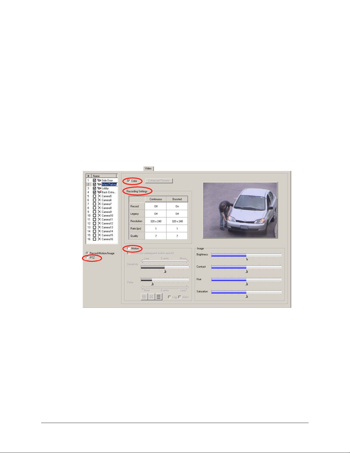
System Administrator’s Guide
resolution of images is automatically adjusted for an optimal view of the video feed. See the
Eye View Software Operator Guide, for more procedures and tips about live video.
Tip
The resolution of recorded video is setup in a Maintenance Session and does not change
when View software automatically optimizes the resolution of live video.
Smoothing video
Video smoothing is an option of View, set by the View operator. It adds a load to the operator's
CPU and can slow busy systems. The result of video smoothing is not recorded; it can be toggled
OFF/ON while watching recorded video or while monitoring Live video. In a Maintenance Session,
video smoothing can be seen in the Enhanced Preview window. See
Resolution, p.
74. See also the Rapid Eye View Software Operator Guide.
Other Video Settings
Fig. 5–2. The Video Tab: Color, Recording Settings, Motion and PTZ.
Rapid
The Enhanced Preview of
Color
You have the option of specifying if a color video feed is viewed in color or in black and white
(b&w). Removing the checkmark from the Color box on the Video tab shows the video feed in
b&w. See figure
needed.
Recording settings
Use the Recording tab to setup the Continuous video recording settings. The values are reported
on the Video tab. See Recording Video: Continuous Recording Settings, p. 68.
Motion
For
Motion Detection, see p. 116.
Document K14392V1 Rev A 67
07/07
5–1, above. Color continues to be recorded and can be toggled in/out, as
Page 68

Video Feed Setup
PTZ
See
Pan, Tilt, and Zoom (PTZ) Setup on p. 85 and Using a PTZ Camera, p. 88.
Screen area: size of camera windows on a PC monitor
If the resolution settings for a Multi-Media unit take-up too much or too little of the PC monitor's
area, adjusting Microsoft Windows’ Display Properties for a PC monitor can have a positive effect.
See Customizing Windows for a PC Monitor’s Settings, on p. 82.
Recording Video: Continuous Recording Settings
Making use of a Maintenance Session
To setup a video feed, continue or start a
so is shown on p.
Fig. 5–3. The Recording Tab, Showing that Three Cameras Are Recording.
53.
Maintenance Session for the Rapid Eye site; how to do
To Enable the Recording of a Video Feed
1. Continue or start a Maintenance Session.
5–3, note that in the Record column, recording
68
2. On the Recording tab, illustrated in figure
is "OFF" by default, for all cameras, when the unit is new. Cells that are unavailable
indicate that that camera port is not connected to a camera, or that the camera is
disabled.
3. Click the cell in the camera's Record column. A menu appears. Select "ON". The settings
for Continuous and
Feedback on the Video tab
On the Video tab, note that a red dot has appeared, between the camera's icon and its name in
the Name column. The dot means that the unit is recording that video feed.
Event Recording become available.
Page 69

System Administrator’s Guide
Fig. 5–4. A Red Dot Is Added to the Icon of a Camera that Is Recording.
Turning recording OFF
A camera's settings are retained when recording is turned OFF.
Disabling a camera resets the recording settings and other configurations to default
settings. The defaults are used when the camera is re-enabled.
Customizing Settings for Recorded Video
Flexibility
Use the Recording tab to customize a Resolution, Frame Rate and Quality for each camera's
continuous recording and for event recording. The recording settings can be the same for all
cameras or customized, camera-by-camera.
Making settings
Values for Event Recording cannot be lower than settings for Continuous recording.
Forecasting results
For
Computing the Length of the Video Archive, see p. 122.
To compare resolution settings, see
Resolution Setting
On the Recording tab, click a cell in the Resolution column. Select a value (of pixels × pixels) from
the list that appears. For comments about the values, see
Resolution Reference: Recorded Video, starting on p. 81. The default values are, for
NTSC: 320 × 240; for PAL: 384 × 288.
Tip
Honeywell recommends optimizing the resolution of recorded video using the Automatic
DSP Performance Maximization.
Comparing the Resolutions of Recorded Video, p.76.
Optimizing Recorded Video, p. 72, and
Honeywell does not recommended gauging the resolution of recorded video based on live
video. Live video is always shown at an optimal resolutions that can differ from the
Document K14392V1 Rev A 69
07/07
resolution for recording.
Page 70

Video Feed Setup
Frame Rate Setting
On the Recording tab, click a cell in the Frame Rate column. Select a value (of images per second
(ips)) from the list that appears. The default value is: 1 ips.
Table 5–1 Frame Rate Values (Approximate ips) for Multi-Media DSP Units
NTSC 1 2 3 4 5 6 7.5 10 15 30
PAL 1 2 3 4 5 6 8 12.5 25
Using lower frame rates
Frame rate and resolution. Units can record up to 30 ips from each NTSC camera (up to 25 ips for
PAL), at the default resolution. Setting a higher resolution may require lowering the frame-rate.
Slower fast-forward or rewind. More ips take more time to process. If recording rates of one or two
images per second are satisfactory; then use them.
Security video and commercial video. The movement of persons recorded at higher rates appear
smoother; however, consult your security personnel about what they need from video surveillance.
Two or three frames per second may be wholly adequate for some security needs.
Quality Setting
On the Recording tab, click a cell in the Quality column. Select a value (a compression factor) from
the list that appears. The values range from: 6 to 10. The default value is: 7.
Quality and the storage of video. Lower values take less storage and can display block-like
artifacts in the video. The highest setting can double the use of storage.
To Duplicate Settings
Using one camera as a template for others
For convenience, recording settings can be copied to all cameras. To do so:
• Right-click in the row that you want to use as a model for the others. A menu appears for
duplicating all settings, or only the settings for continuous recording, or event recording. See
5–5.
fig.
Restoring defaults
• Right-click on the Recording tab. A menu appears. Click "Reset all cameras to default values".
See fig.
Fig. 5–5. The Menu for Duplicating Recording Settings (1) or for Restoring Defaults (2).
5–5.
70
Page 71
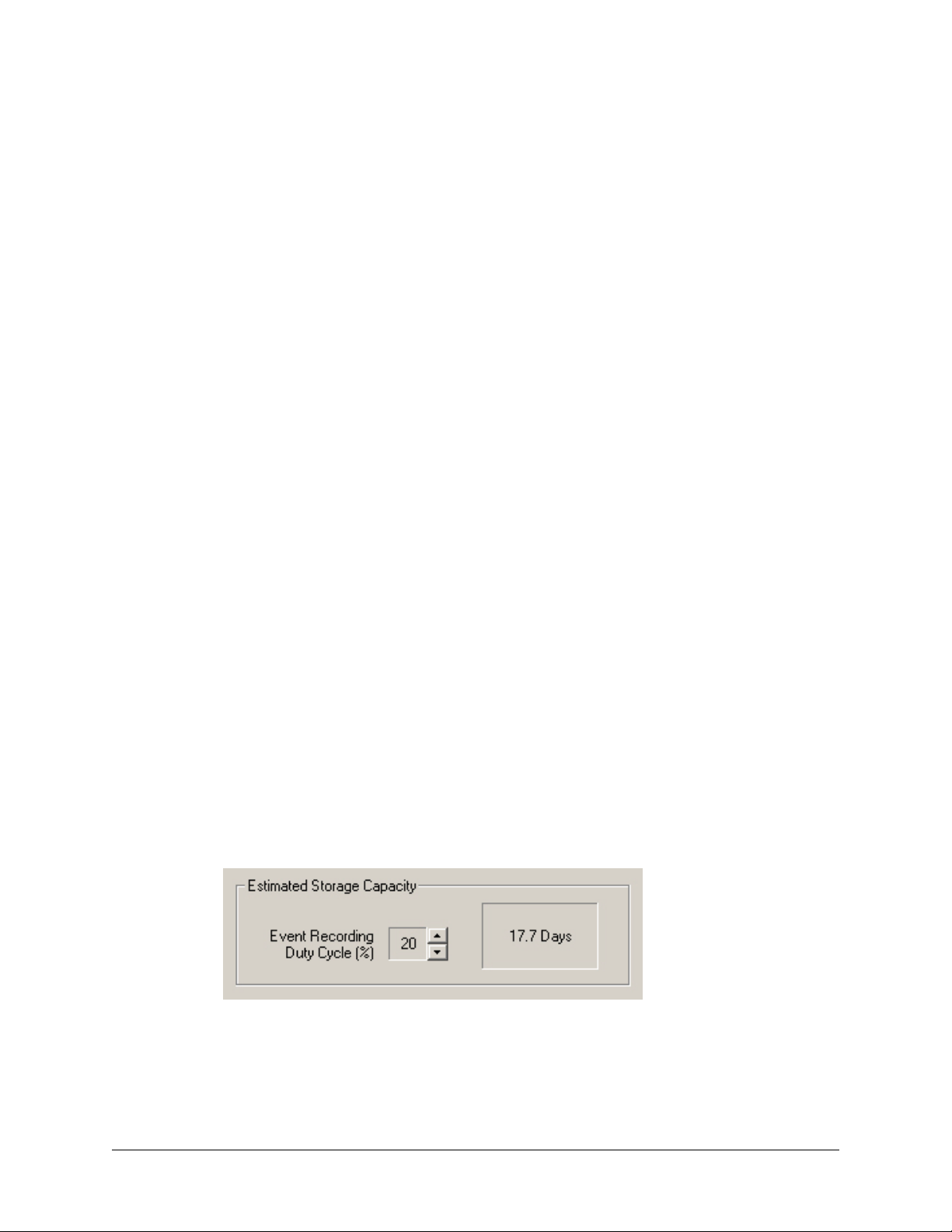
System Administrator’s Guide
Continuous Recording and Event Recording
To use event recording, set different values for the Resolution, Frame Rate and Quality of from
those for continuous recording.
Authority
The settings for recording video are made by your organization’s Multi System Administrator
(Multi SA) or by a user with the Modify Configuration right in her account.
A Multi SA can consult View operators, security personnel and IT managers, to find out if:
• The recorded video is satisfactory for the needs of your organization.
• The settings do not shorten the video archive to the point of making it unusable.
Report
The values selected on the Recording tab are also shown on the Video tab.
See also
Event Recording: Configuration, p. 103.
Estimating Storage Capacity
A unit’s video archive
As higher values for Rate, Resolution and Quality are set, the time that video, audio and data can
be stored in a unit—the video archive—, shortens. The Estimated Storage Capacity reports a
useful forecast (in days) of the length of the video archive. See fig.
Length of a unit’s video archive
The Event Recording Duty Cycle can give more precision to the estimate of the unit’s video
archive. Base the duty cycle on how often events and operators will be using the
Recording settings (% of recording time). The estimated length of the video archive is shown next
Event Recording Duty Cycle.
to the
Fig. 5–6. Estimating a Unit's Video Archive.
5–6.
Event
Document K14392V1 Rev A 71
07/07
Page 72

Video Feed Setup
Table 5–2 Event Recording: Duty Cycle Cutoffs
Duty Cycle
(% of recording time)
0 continuous recording only
10, 20, 30, 40, 50, 60, 70, 80, 90 mostly continuous recording (10),
100
Rapid Eye Storage Estimator
To make storage estimates using more parameters (scheduling, audio, motion and so on),
Honeywell’s
Rapid Eye Storage Estimator is installed with Rapid Eye software. See p. 123.
Estimate for…
to mostly event recording (90)
event recording only
Optimizing Recorded Video
Flexibility
To optimize the many setup options quickly, use the
Performance maximization can be performed using View software or LocalView. The Quality
settings are not affected by it. The result of maximizing performance is shown on the Recording
tab and on the Video tab.
Preparation: contiguous connections
Automatic Maximization of DSP Performance.
For optimization the digital signal processing (DSP) of video and its storage, an installer needs to
make camera connections contiguous, on the back of a unit. Connections are said to be
contiguous if they start at camera VIDEO INPUT 1 and continue sequentially. For example:
Connecting three cameras to inputs: #1, #2 and #3 is contiguous; connecting the cameras to
inputs: #1, #3 and #4 would not; nor would using inputs: #2, #3 and #4.
Automatic Maximization of DSP Performance
Gauging the processing load
The load on DSP is reported on the gauges for DSP Bandwidth Utilization, as you use the
Recording tab to customize the settings of recorded video. See fig.
Fig. 5–7. Load on DSP Resources.
5–7.
72
Page 73

System Administrator’s Guide
Automatic display of Maximization tool
If settings are too high, the "DSP Bandwidth Utilization", the Automatic DSP Performance
Maximization window is displayed. See figure
Fig. 5–8. The Automatic DSP Performance Maximization Window.
5–8.
Optimization options
The list of options changes depending on:
• The use of NTSC or PAL
• The number of cameras connected to the unit. Optimization cannot be used if the cameras are
not connected contiguously. See
Optimizing Recorded Video, p. 72.
Document K14392V1 Rev A 73
07/07
Page 74

Video Feed Setup
Making Optimized Resolution and Frame Rate Settings
In the Automatic DSP Performance Maximization window (see fig. 5–8), double-click an "automatic
option".
Manual display of Maximization window
To display the Automatic DSP Performance Maximization window, click the "Configure Automatic
Optimizations" command, after right-clicking on the Recording tab. See fig.
Fig. 5–9. The Configure Automatic Optimizations Command.
5–9.
The Enhanced Preview of Resolution
1. Continue or start a Maintenance Session for the Rapid Eye site.
2. On the Video tab, select a camera name in the Name column. The Enhanced Preview
button is available if the camera is recording. A camera that is recording is identified by a
red dot, between its icon and name.
3. Click Enhanced Preview. In figure 5–10, below, the detail (1) shows a feed recorded at
a low resolution of 160 x 120, at the size that it would appear on a monitor. The outlines
(2) show the optimal size of a video feed on the PC’s monitor for that resolution. The
many circled resolution labels (3) can be used to display another recording resolution.
4. You have the option of experimenting with:
• Viewing the video feed at optimal size for a resolution. Click on the resolution
labels, within a resolution outline or use the Resolution setting on the Recording
tab.
• Stretching the video image. To compare resolutions at other “image sizes”, drag
the lower-right corner of the video image. The Image Size box reports the size of
the stretched image.
• Displaying or hiding outlines and labels on the video preview. Select Show
outlines and Show resolution labels as needed.
74
Page 75

Fig. 5–10. The Enhanced Preview Window.
System Administrator’s Guide
Resolution Tips
The following tips prolong your unit's archive of video through lowering the resolution of recorded
video.
Do you need to establish an individual's "presence" or a person's identify?
• Presence may be sufficient. For tasks that only involve establishing if "someone has entered
the building", or counting cars in a parking lot, and so on, low resolution may be “good
enough” to establish presence, helping to guarantee a longer video archive; see figure
How many cars? Objects can be effectively counted at low resolution make using high
resolution unneeded.
• Identification is needed. Unknown vehicles, a person's facial traits and so on, camera position
and higher-resolution may be needed. Identification may not be as crucial when subjects are
known: employees, uniformed personnel, and so on.
• You have the option of adjusting Microsoft Windows’ Display Properties for your PC monitor.
Customizing Windows for a PC Monitor’s Settings.
See
5–13.
Document K14392V1 Rev A 75
07/07
Page 76
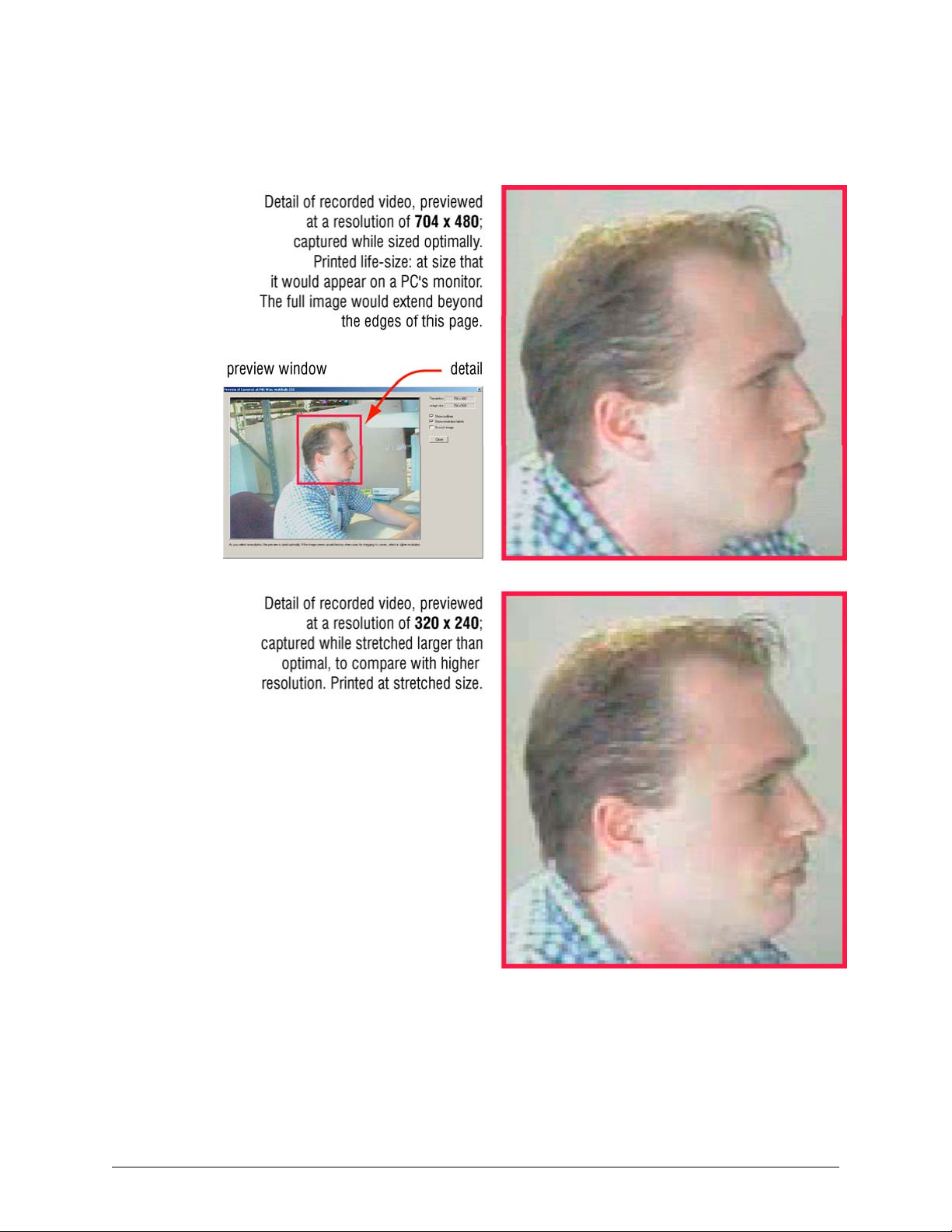
Video Feed Setup
Comparing the Resolutions of Recorded Video
Fig. 5–11. Using High or Moderate Resolution, 320 × 240 (NTSC), to Identify a Subject.
76
Page 77

Security and Presence
Before critical events occur, it is worthwhile to compare video recorded at Continuous values with
video recorded using Event values. You can establish if the resolution is high enough for your
organization’s security needs. Consult your security personnel to find out whether you need to:
• Establish the presence of known individuals. Lower resolutions are usually adequate and take
less storage. Some samples of low-resolution and high-resolution video images are shown in
Comparing the Resolutions of Recorded Video, p. 76.
Video images are bitmaps. When a camera window is dragged to a larger size, the pixels of the
video feed are also enlarged. The image’s sharpness is not preserved; more stretching can
degrade the subject of an image beyond recognition. Compare figures 5–11 and 5–12. A high
resolution of 704 × 480 (NTSC) shows recognizable facial characteristics and very few artifacts—
such as “pixelation”, color variance and so on. If storage time is an issue, recordings at a more
modest resolution of 320 × 240 shows almost as much detail. Applications to establish presence
or absence of personnel can use even lower resolutions. At 160 x 120 (NTSC) many facial
characteristics of a known person are still recognizable even when the imaged is stretched, as in
fig.
5–12.
Fig. 5–12. Using Low Resolution, 160 x 120 (NTSC) to Show Presence.
System Administrator’s Guide
Document K14392V1 Rev A 77
07/07
Page 78
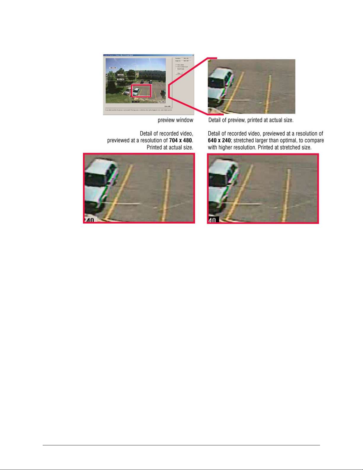
Video Feed Setup
Fig. 5–13. To Establish Presence, Lower-Resolutions May Suffice.
Retouching stills with software
Bitmap editing tools and imaging software can be used to enhance video stills or screen captures.
Though retouching may void the admissibility of the video as evidence in a court of law, it can be
of use to highlight a detail or trait. Commercial software for retouching bitmaps includes: PaintShop Pro, Corel Photopaint, Adobe Photoshop, and others. For screen captures, use Microsoft
Windows, TechSmith’s SnagIt, and so on.
Screen area: size of camera windows on a PC monitor
Adjusting Microsoft Windows’ Display Properties for a PC monitor can have an effect on how
resolution is perceived. See
Customizing Windows for a PC Monitor’s Settings, p. 82.
78
Page 79

System Administrator’s Guide
Camera Tips for Identification: Quality and Resolution
Fig. 5–14. Camera Distance Can Be more Important than High Resolutions.
Camera placement can be a crucial factor when troubleshooting resolution issues. If higher Quality
and Resolution values are insufficient for your video needs, consider consulting your system
installers about:
• Monitoring small or faraway objects. For license plates, facial traits, and so on, the closeness of
a camera to its subject and the ability to zoom can matter as much as, or even more than,
higher resolutions and higher quality.
• Using a gauntlet strategy. To identify vehicles by their license plate, install a camera at an entry
or exit point, at ground level. Close camera shots coupled with high resolution give the best
detail.
• Covering an area with a duo of cameras. One camera at a payment counter can be zoomed to
identify facial characteristics, while another can be installed a little farther away to survey more
of the scene.
• Using higher Quality and lower Resolution. The results can be better, with less impact on the
video archive.
Resolution Gauge for Retrieval Session
The resolution gauge appears when running View software. The resolution gauge for recorded
video differs from the gauge for live video. The gauge for live video is shown and explained in the
Rapid Eye View Software Operator Guide.
A gauge that indicates the resolution at which the recording was made
When an operator runs a retrieval session, a resolution gauge is displayed on each camera
window indicating the resolution at which the video was recorded.
Document K14392V1 Rev A 79
07/07
Page 80

Video Feed Setup
NTSC gauge
The NTSC gauge is shown in figure
The dot changes position when recording settings switch to and from Continuous Recording
settings to Event Recording settings. Here, 640 x 240 continuous, is shown for NTSC. While
Event Recording occurs (2), the dot moves to the right. When the Event Recording stops (3), the
resolution gauge again shows the resolution setting for continuous recording.
Fig. 5–15. Resolution Gauge for Recordings Made with NTSC Cameras.
The dots movement depends on the settings made by your organization's Multi SA for
Continuous Recording and
PAL gauge
The gauge for PAL is shown in figure 5–16. (1) shows a dot that indicates the resolution of video.
The dot changes position when recording settings switch to and from Continuous Recording
settings to
Recording occurs (2), the dot moves to the right. When the Event Recording stops (3), the
resolution gauge again shows the resolution setting for continuous recording.
Event Recording settings. Here, 384 x 288 continuous, is shown for PAL. While Event
5–15. (1) shows a dot that indicates the resolution of video.
Event Recording.
The dots movement depends on the settings made by your organization's Multi SA for
Continuous Recording and
Fig. 5–16. Resolution Gauge for Recordings Made with PAL Cameras.
Event Recording.
80
Page 81
Resolution Reference: Recorded Video
Table 5–3 Recording Resolutions for Multi-Media DSP (pixel × pixel): NTSC and PAL
NTSC
Resolution 160 × 120 legacy† 320 × 240 640 × 240 640 × 480 704 × 480
Comment lowest
resolution
Gauge in a
Retrieval
Session‡
PAL
Resolution 192 × 144 384 × 288 704 × 288 704 × 576
Comment lowest resolution Honeywell’s
Gauge in a
Retrieval
Session‡
320×192;
default for
upgrades
from NTSC,
set at legacy
n/a
default for PAL,
including upgrades
default
when new
unit set for
NTSC
System Administrator’s Guide
also called
“half”
Highest setting for
Multi-Media LT
also called
“full”;
highest
setting for
MultiMedia LT
highest
NTSC
setting
highest PAL
setting
† “Legacy”, used by older Multi units, is included for compatibility. There is no gauge for the
NTSC legacy setting. The Legacy resolution is not shown in the Enhanced Preview.
‡ Gauges are explained at the start of Resolution Reference: Recorded Video.
Table 5–4 Recording Resolutions for Multi-Media LT (pixel × pixel): NTSC and PAL
NTSC PAL
Resolution 160 × 120 320 × 240 640 × 240 192 × 144 384 × 288 704 ×
288
Comment lowest
NTSC
resolution
Gauge During
Retrieval*
* Gauges are explained at the start of Resolution Reference: Recorded Video.
default
setting for
NTSC on a
new unit.
highest
NTSC
setting
lowest PAL
resolution
default
setting for
PAL,
including
upgrades
highest
PAL
setting
Document K14392V1 Rev A 81
07/07
Page 82

Video Feed Setup
Customizing Windows for a PC Monitor’s Settings
Using Microsoft Windows
Honeywell recommends that if operators plan to use View's higher resolution settings:
• The Screen area (for the monitor) be set to "1280 by 1024 pixels" or higher to run View.
Microsoft Windows is used to set this value, not View software. Recommended values are listed
in table 5–5. The PC monitor’s refresh rate can also be changed. See Larger Monitors and
Microsoft Windows, p.
Honeywell also recommends that if you plan to display ten or more cameras at once on a PC
screen that you consider:
• Using two PC monitors at the same time. See Microsoft Dual View and Rapid Eye View
Software, p.
Table 5–5 Display Properties for Optimal Rapid Eye Video at Higher Resolutions
82.
83.
Screen area
(pixels)
1600 by 1200 yes yes
1280 by 1024 yes yes
1280 by 960 yes yes
1152 by 864 no * yes
1024 by 768 no yes
800 by 600 no no*
* Video is visible and workable even when using smaller screen area settings; see figure 5–17.
** Dial-up connections using few cameras are faster, as is retrieval of video recorded at lower
resolutions. Lower settings for Screen area may be sufficient for such use.
For Multi-Media DSP For Multi-Media, Multi-Media LT and
PC Monitor’s Refresh Rate
Higher refresh rates can alleviate eye fatigue when monitoring video over time. You can change
the Refresh Frequency, and the refresh rate (Hertz), as needed.
Not all monitors and video cards support the resolutions indicated in the preceding sections, nor
do all offer various refresh rates. Consult the documentation supplied with Microsoft Windows,
your monitor and the video card.
over dial-up connections**
Microsoft Dual View and Rapid Eye View Software
Using two monitors and running View software
Two monitors can be effectively used with Multi-Media View to display more camera feeds at once.
To set up a Dual View system, see your Microsoft documentation. Hardware note: a second video
card is needed on the View operator’s PC for Microsoft’s Dual View setup.
82
Page 83

Larger Monitors and Microsoft Windows
Fig. 5–17. Microsoft Windows’ Screen Area Settings.
System Administrator’s Guide
Setting Microsoft Windows
Larger computer monitors and better video cards are assets when setting Microsoft Windows for
high Screen area settings. Note how in figure
the screen area changes—a camera window is highlighted for comparison. More cameras can be
seen at once, and at higher resolutions (here five cameras at 320×240 resolution) when a
recommended setting is used, as in A or B. Even at settings that are not recommended, video can
still be viewed, though: some camera windows can appear to extend beyond the monitor’s
surface. At any setting, camera windows can be dragged as needed and the player window
scrolled.
Document K14392V1 Rev A 83
07/07
5–17, the change in size of the camera windows, as
Page 84

Video Feed Setup
Environmental Interference for Video Feeds
Preventive measures
Checking one’s installation for hard-to-predict situations includes spot-checking:
• Live video. Run a Live Session on a regular basis. Such spot checks offer confirmation that sites
have not been vandalized, rendered ineffective by the environment or tampered with by an
operator. See “physical compromise”, below.
• Recorded video. After a day or two, run a retrieval session to look for artifacts in recorded video,
at every half-hour or so, over a 24 hour period. The darkness of night or bright sunlight may
indicate the need for changes in camera position or lighting. For outdoor cameras, it can be
worthwhile to run such spot checks seasonally. See “physical compromise”, further down.
• After use of PTZ. A camera with the ability to pan-tilt and zoom can be set to respond in a
variety of ways after use and should be spot-checked. Run a retrieval to do so. See
PTZ After a Session Closes, on p. 93.
• Scheduling. The video archive can be spot-checked for recorded video when cameras are
scheduled to record it. For scheduling, see
Scheduling: Configuration, p. 105.
Behavior of
Physical Compromise
Even when cameras are set as recommended, changing environmental factors can compromise
video at the source. Obvious factors include:
• Direct sunlight at short times during the day. Daybreak can interfere with recording for cameras
aimed East, as can sundown for cameras pointing West.
• Dew, frost or kitchen grease. Check camera lenses, or windows between the camera and the
subject for transparency and cleanliness.
• Darkness. Without lighting or infrared cameras, indoor rooms and nighttime can make cameras
ineffective.
• Cameras at an outside window, in a room that remains lit during evenings. Reflection from the
window can hamper or block visibility outside.
• Opaque objects. Even small objects can obstruct a camera when near and hamper an
operator’s view of a site. Large mobile objects, such as a truck also can be used to
compromise video of an event. See also “vandalism”, below.
• Power outage. Even when plugged into a UPS, prolonged power outages can compromise the
recording of video.
• Vandalism. Tampering with cameras, Multi-Media units or other hardware. This can be done by
damaging hardware directly or indirectly interfering (by spraying paint, fog or moving objects in
the way), or even through reconfiguration, using View software.
84
Page 85

Pan, Tilt, and Zoom (PTZ) Setup
Flexibility
Use of panning-tilting and zooming (PTZ) is optional, even with cameras that have the capability to
pan, tilt and zoom. Not all cameras have PTZ features. Check with your installer if you are unsure.
Preparations
To prepare a Multi-Media unit to use cameras with PTZ capability, a Multi SA needs to setup a:
• Serial device for PTZ. A Multi SA can consult the installer to find out which serial ports of the
unit are connected to the serial communications line of PTZ domes / PTZ cameras. For setting
a PTZ device, see the procedure:
To Assign and Set a New PTZ Device, below.
6
• On Multi-Media units with three or more serial ports, use any port for PTZ. For units that have
only two serial ports, Honeywell recommends that PTZ domes be connected to port 2; other
serial devices might be assignable only to port 1.
• Many domes, daisy-chained can be connected to the Multi-Media unit if they use the same
Communications settings for PTZ. For the address set on each camera, consult the installer.
Other dome communications settings can be found in the dome-manufacturer’s
documentation.
Serial Device Settings for PTZ
Fig. 6–1. Assigning a PTZ Driver to a Port on the Multi-Media Unit.
Document K14392V1 Rev A 85
07/07
Page 86

Pan, Tilt, and Zoom (PTZ) Setup
To Assign and Set a New PTZ Device
1. Find out to which serial port on the Multi-Media unit is connected to the PTZ dome(s).
The installers connected the Data In port of domes (an RS-485 connector) to either:
• One of the serial ports on a Rapid Eye unit. The port number for a dome can
differ from that of another dome.
• A bus, connected to one of the serial ports on a Rapid Eye unit. The port number
is the same for the domes on that bus.
2. Continue or start a
3. Click the Serial Devices tab.
4. Expand the New Devices group.
5. Drag the PTZ icon to the Port that matches the unit’s serial port identified in step 1. If you
drop the icon on a port that is already assigned to another device, the PTZ device
displaces it; the displaced device is sent to the Unassigned Devices group.
6. You have the option of renaming the device. Click the Device Name box and type. A
maximum of thirty-two characters and numbers are allowed, including spaces.
7. Select the serial interface protocol: RS–232, RS–485, or RS–422.
8. You have the option of:
• Selecting the Enable Controller Switch. A checkmark sets the Multi-Media unit’s OUTPUT 1 to
send a signal whenever a PTZ camera is selected during a Live session. Installers can connect
OUTPUT 1 to the external controller so that the signal disables the controller while a Multi-Media
operator uses a PTZ camera. When a PTZ camera is not selected, the signal from output 1
stops so that control of the PTZ serial bus is returned to the external controller.
• Assigning another PTZ device to another Port (or to the Unassigned Devices group). To do so,
repeat steps 4 to 7.
ACUIX dome camera domes
For
ACUIX dome camera domes, you have the option of using the Intellibus PTZ driver. See
ACUIX Dome Camera, on p. 99.
Maintenance Session.
Video Tab Settings for PTZ
Preparations
Assign a PTZ serial device, as explained in procedure
above. The device can be assigned to either:
• One of the ports on the Multi-Media unit.
• The Unassigned Devices group.
Tip
86
The signal format for all cameras (NTSC, PAL) is set on the System tab.
See System Tab in a Maintenance Session, p. 134.
Using many PTZ domes/cameras on one serial communications line
If more than one PTZ camera share the same serial communications line. If so, make a note of:
• The address set on each camera.
• The driver needed for the make and model of dome; if the domes require different drivers, they
cannot share the same port/serial communications line.
To Assign and Set a New PTZ Device,
Page 87

To Enable a PTZ Camera
1. Continue or start a Maintenance Session for the Rapid Eye site.
2. Click the Video tab.
3. Click PTZ. See figure
4. Select the Enable box. The PTZ boxes and the PTZ controller become available. Note:
the Enable box is not available if a PTZ serial device is not assigned. To assign a PTZ
device, see the procedure:
System Administrator’s Guide
6–2.
To Assign and Set a New PTZ Device, above.
5. Select a driver that matches a PTZ camera. Drivers are listed in table
6. If more than one PTZ camera is sharing the device, select a Camera Address that
matches the address set on the dome hardware.
7. Select the port attributes of the PTZ dome: Data bits, Stop Bit, Baud Rate and Parity Bit.
8. Select the position that a PTZ camera takes after a View operator closes a Live Session.
Consult your security officer before changing the value in the When Live Closes box. See
Behavior of PTZ After a Session Closes and table 6–2, on p. 94.
9. Cameras that have a command menu can be set using the Camera Menu button. Use
the dartboard control or the rubber band control to choose a command; use the Select
button to change a value. The PTZ controls are explained next, in section
Camera.
Fig. 6–2. Configuration Settings (4) for a PTZ (3) Camera (2), on the Video Tab (1).
6–1.
Using a PTZ
Document K14392V1 Rev A 87
07/07
Page 88

Pan, Tilt, and Zoom (PTZ) Setup
Table 6–1 PTZ drivers for controllers and domes
Driver (name)* Baud (rate) Support for (dome/controller/PIT device)
Bossware 19200 PIT device, to which domes are connected.
Honeywell Fixed Camera 9600 Honeywell HCU484
Intellibus 38400 ACUIX dome camera
Javelin 308 9600 Javelin 308 Controller
Kalatel 9600 or 2400 Kalatel KTD 312 Cyberdome
Pelco D 4800, 9600, or 2400 Pelco D
Pelco P 2400 Pelco P
Rapid Dome/Orbiter 9600 RapidDome or Orbiter
SensorMatic RS422 4800 SensorMatic RS422: Delta and Speed
Ultrak (using VCL) 2400 Ultrak (configured as VCL)
Ultrak KD6 9600 KD6, HD6, HD6i
* The drivers are not listed alphabetically in the software. A driver can be used with domes other
than those listed. For other domes, controllers or PIT devices, consult their documentation.
Using a PTZ Camera
Three PTZ controls are available to make PTZ commands: a dartboard-like control, a rubber band
control and a Zonal Mode control.
Either is available while running a Live session or while using LocalView. The right to use a PTZ
camera is granted in the operator’s Multi-Media account; see
To Display the PTZ Dartboard Control
The PTZ dartboard control can be obtained in three situations:
• During a
tab. See the first steps of procedure
• During a Live session, select or add a video stream from a PTZ camera. Click
PTZ Control" button.
• In LocalView, a “PTZ” button is shown when a Live tab is selected. It is available when a PTZ
camera is selected.
Maintenance Session, when PTZ is selected, the PTZ control is displayed on the video
To Enable a PTZ Camera, above.
Granting Rights, p. 158.
, the "Enable
88
Page 89

Using the Dartboard Control
Fig. 6–3. Dartboard Control for PTZ camera, Showing Command Feedback.
System Administrator’s Guide
1. On the PTZ Control, click either Click or Hold.
2. Move the mouse pointer over the dartboard-like control to highlight areas of the
dartboard. Each area on the dartboard offers textual feedback in the box, below the
control. See figure
3. Click when the command that you need is highlighted. If you are using the Hold option,
the mouse button can be held pressed to make the command last as needed.
6–3.
Toggling between Zonal Mode and Pull Mode
1. In a Live player, select a PTZ camera.
2. In the View menu, select Options.
3. Click Zonal PTZ Control Mode.
• If there is no checkmark next to the command, Zonal mode is enabled and
replaces the Rubber-Band-like control (Pull Mode).
• If there is a checkmark next to the Zonal PTZ Control Mode command, Zonal
mode is replaced by the Rubber-Band control.
Tip
The rubber-band control cannot be used at the same time as the zonal mode control, and
vice-versa.
Document K14392V1 Rev A 89
07/07
Page 90

Pan, Tilt, and Zoom (PTZ) Setup
Pulling the Rubber-Band
Fig. 6–4. Dragging the Mouse Pointer in a PTZ Camera Window.
On the video image, click and drag the mouse. A line is overlaid on the video. Lengthening the line
speeds-up the PTZ camera’s panning or tilting. See figure
• Pan. To pan right and to tilt down, slightly, drag the pointer from (1) to the right (2). In View, the
band has a single color; here, it is highlighted for illustration.
• Zoom. Use the wheel on the mouse. If the mouse does not have a wheel, see
Dartboard Control,
• Presets and other commands. In a Live session and in LocalView, right-click on a PTZ
camera’s video to obtain a menu of PTZ commands and video resolution commands. In a
Maintenance Session, use the commands on the dartboard.
Using Zonal Mode
Fig. 6–5. Using PTZ Zonal Mode.
6–4.
Using the
above.
90
Page 91

System Administrator’s Guide
• To pan or tilt, move the mouse through the PTZ camera’s window until the pointer changes to a
numbered arrow. Click. Figure
panning or tilting, click the arrow furthest from the center.
• To stop continuous panning or tilting, move the mouse through the PTZ camera’s window until
the pointer changes to an octagon. Click.
6–5 shows the Zonal Mode for panning left. For continuous
• To zoom, use the wheel on the mouse. If the mouse does not have a wheel, see
Dartboard Control,
above
Programming a PTZ Dome Camera
Fig. 6–6. PTZ Dome Camera without Auto-focus (1) or with, Between the Dots (2).
Using the
PTZ preset
Presets are set during a Maintenance Session. A PTZ camera can be set to return to the first
preset when use of the camera ceases, when a Live session ends.
Auto-focus
View supports an auto-focus control when two dots appear in the “– Focus +” arc of the PTZ
controller. Click between the dots to toggle auto-focus ON/OFF. See figure
Auto-iris
View supports an auto-iris control when two dots appear in the “– Iris +” arc of the PTZ controller.
Click between the dots to toggle auto-iris ON/OFF.
6–6.
To Configure a Preset on a PTZ Camera
1. Continue or start a Maintenance Session.
2. Click the Video tab.
3. Click PTZ.
4. Select a camera whose PTZ preset you need to set.
Document K14392V1 Rev A 91
07/07
Page 92
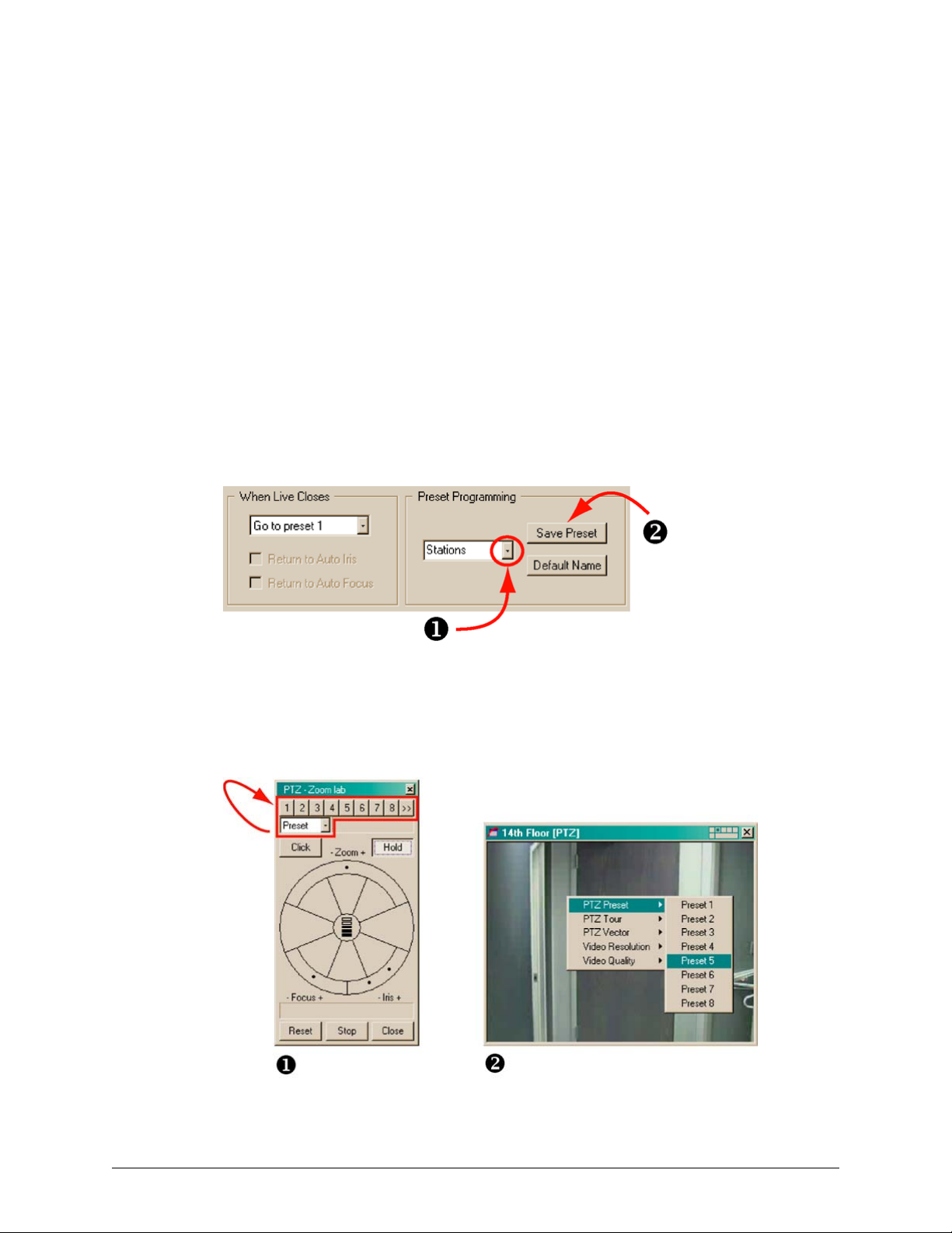
Pan, Tilt, and Zoom (PTZ) Setup
Tip
5. In the Preset Programming area, click the arrow button; see figure
appears; by default, it contains “Preset 1”, “Preset 2”, “Preset 3” and so on; in all: 127.
Preset 1 may have been already set by an installer, to be used after close of session. See
Behavior of PTZ After a Session Closes, p. 93. Consult your site’s installer or security
officer before changing the first preset of a PTZ camera.
6. Click an item in the Preset Programming list.
7. You have the option of renaming the preset by typing into the box.
8. Set the camera's pan position, tilt angle and zoom amount, as explained in
Dartboard Control, p.
9. Click Save Preset. The camera's pan position, tilt angle and zoom amount are saved.
10. You have the option of immediately:
• Setting another preset. Repeat steps 4 to 9, using another preset in step 6.
• Testing the preset. See the next procedure.
• Setting presets for another PTZ camera at that site.
Fig. 6–7. Programming a PTZ Preset.
89. Continuous panning can also be selected.
6–7, below. A list
Using the
To Te s t a P r e s e t
Fig. 6–8. Testing Presets on a PTZ Camera.
92
Page 93

1. You have the option of running either:
Maintenance Session. Click the Video tab, select a PTZ camera whose
• A
presets are to be tested, and click PTZ; the PTZ dartboard controller is displayed.
System Administrator’s Guide
• A Live Session. select or add a video stream from a PTZ camera. Click
the "Enable PTZ Control" button. The dartboard controller is displayed.
2. On the dartboard control, leave or set the drop-down arrow box to “Preset”.
See figure 6–8.
3. Click the numbered buttons above the Preset box. The PTZ camera moves to the preset
position. If the camera does not move, check your configuration. Either:
• A preset has not been set for that number.
• The preset duplicates the settings of the one used previously.
• The camera is indicated as being PTZ but is not.
PTZ and motion detection
When an alarm based on motion detection is enabled on a PTZ camera, use of PTZ functions will
most likely trigger that alarm. You can limit the number of alarms triggered by using the Delay
slider in the motion detection controls. The alarm schedule can also be changed to stop alarms at
certain times when PTZ use is anticipated. See
on p. 187.
Ultrak KD6i domes
auto-iris. Before an aperture setting can be changed manually on an Ultrak KD6i dome, the
operator needs to turn OFF the auto-aperture. Auto-aperture is also known as “auto-iris” on the
PTZ controller.
Motion Detection, on p. 116 and Events Defined,
,
return to auto-focus. This command has no effect on Ultrak KD6i domes.
Kalatel domes
On Kalatel domes, the iris controls in View toggles coarse brighter/darker settings, not a gradual
open or close. Auto-iris has no effect.
Behavior of PTZ After a Session Closes
Position of PTZ camera after close of session
When a Live Session ends, a security officer may need a PTZ camera to return to a set direction
and zoom, while the camera is not being monitored by a View operator.
Fig. 6–9. PTZ Camera: Behavior after Use.
Document K14392V1 Rev A 93
07/07
Page 94

Pan, Tilt, and Zoom (PTZ) Setup
1. Using View, continue or start a
pan, tilt and zoom (PTZ) need their post-session behavior set.
2. Click the Video tab.
3. Click PTZ. Check if the Enable box shows a checkmark. Post-session behavior cannot
be set unless PTZ is enabled.
4. Click the arrow of the When Live Closes box; select a post-session behavior; they are
listed in table
Table 6–2 Position after Close of Session, for PTZ Cameras
At Session End Comment / Behavior
Stay put The camera remains in the last position used by the operator. If it is
Go to preset 1 The camera returns to “preset 1” configured using Multi. See the
Start tour 1* Some camera models can be programmed to move independently when
* A “PTZ tour” differs from: (a) site tours (see Touring Many Sites) and (b) local camera tours using
a monitor at the Multi-Media site.
6–2.
panning, it keeps on panning; if it is not moving, it stays that way, and so
on. The “stay put” behavior makes available the Return to Auto-iris and
Return to Auto-focus options.
procedure: To Configure a Preset on a PTZ Camera, on p. 91 for
configuring the first preset of a PTZ camera.
not in use by an operator. For information on how to program a PTZ tour,
see the documentation that came with the domes connected to the MultiMedia unit.
Maintenance Session at a site where camera(s) featuring
PTZ and motion search
Video recorded while a PTZ dome or camera can be searched for motion. When the camera is
fixed, results are as expected; see
on video recorded as a PTZ camera is panning, tilting or zooming. If you plan to use motion
search on a PTZ camera, use “Stay put” or a preset after close of session. See table
Motion search can also be used to find out when a PTZ camera was moved, if that camera should
be staying put.
Constant panning and video archive
Recording a video feed from a camera that pans constantly requires much more storage. If the
duration of your video archive is a concern, see
Ultrak KD6i dome: restriction
Return to auto-focus. Has no effect on the Ultrak KD6i dome.
Do not use the “Return To Auto-Iris” on Ultrak KD6i domes.
Motion Search, on p. 120. However, motion search is ineffective
6–2.
Quality, p. 125.
94
Page 95

Support for RapidDome PTZ Features
A Multi SA can preset a RapidDome PTZ dome, using View software, for:
• Mimic tours. A mimic tour recalls the commands to pan, tilt and zoom, that were sent to a
RapidDome camera. Mimic tours are also known as path tours.
• Preset tours. A “preset tour” recalls a list of PTZ presets. Before setting up a preset tour,
someone is needed to setup presets.
• Privacy zones. Use presets 100 to 127. The video feed is not displayed when a dome is
positioned at these presets.
Fig. 6–10. Detail of PTZ Setup for the RapidDome Driver.
System Administrator’s Guide
Detail of PTZ setup for the RapidDome Driver, on the Video tab, during a
Details show controls for the mimic tour (1), preset tour (2) and privacy zone (4). The selection of
presets and tours is made using the list (3) above the PTZ controller. In the list, “Vector” is used to
select a preset tour.
Maintenance Session.
RapidDome PTZ Tours
1. In the PTZ controller, click the arrow in the box under the row of numbered button to
display a list, showing: “Preset, “Tour” and “Vector”. See figure
2. Do one of the following:
• For mimic tours, select “Tour”.
• For preset tours, select “Vector”.
3. Click a button in the row of numbered buttons, above the box that shows the list.
Document K14392V1 Rev A 95
07/07
6–10–(3), on page 95.
Page 96

Pan, Tilt, and Zoom (PTZ) Setup
RapidDome Mimic Tour
1. While using View, select a site that has one or more RapidDome PTZ cameras.
2. Run a
3. Select a dome camera.
4. Click PTZ. Check if the Driver is “RapidDome/Orbiter”. If not, this procedure cannot be
5. Click Program. A message appears below the buttons in the Tour Programming section:
6. Pan, tilt and zoom the camera, as needed.
7. Click End.
8. You have the option of programming another mimic tour for the dome camera; repeat
Maintenance Session; click the Video tab.
used. In the “Tour Programming” section, the Mimic Tour is selected by default. See
6–10, above. You have the option of selecting which of the four mimic tours you
figure
plan to setup. To do so, click the arrow button above the End button. A list appears,
showing “Tour 1, Tour 2, Tour 3 …” by default. Click an item in the list.
“Tour Programming in progress …” See figure
• You have the option of testing the mimic tour by clicking Test.
• You have the option of renaming the mimic tour. Click inside the box in the Tour
Programming section. Type a name. Save the name by clicking the mouse.
steps 5 to 7 as needed.
6–10, above.
To Te s t a M i m i c To u r o n a R a p i d D o m e C a m e r a
1. While using View, select the site at which you have programmed a mimic tour on a
RapidDome camera, as shown in procedure RapidDome Mimic Tour.
2. Run a
3. Click PTZ. Check if the Driver is “RapidDome/Orbiter”. If not, the wrong camera or site
4. In the “Tour Programming” section, select a mimic tour, using the arrow button above
5. Click Test.
Maintenance Session; on the Video tab, select the dome camera that is
programmed with a mimic tour.
may have been selected and this procedure cannot be used.
the End button. By default, they are named “Tour 1, Tour 2, Tour 3 …”
RapidDome Preset Tour
Before setting up a preset tour, set some presets. See To Configure a Preset on a PTZ Camera, p. 91.
Fig. 6–11. Right-clicking in the Tour Programming table reveals the Insert command.
96
Page 97

System Administrator’s Guide
To Setup a Tour of Presets on a RapidDome Camera
1. While using View, select a site that has RapidDome PTZ cameras.
2. Run a
3. Select a dome camera.
4. Click PTZ. Check if the Driver is “RapidDome/Orbiter”. If not, the remaining steps in this
5. To add a preset to the preset tour, right-click in the table in Tour Programming. A menu
6. Click the Insert command. A preset is added to the list.
Maintenance Session; click the Video tab.
procedure cannot be used. In the “Tour Programming” section, click Preset Tour
(Vector). While a preset tour is being programmed, the RapidDome dome does not
move. You have the option of selecting which of the four preset tours you plan to setup.
To do so, click the arrow button above Dwell Time. See figure 6–11 (2). A list appears,
showing “Vector 1, Vector 2, Vector 3 …” by default. Click the name that you need.
appears, showing an Insert command, as in figure
• Speed. You have the option of setting the time (in seconds) that the dome will
take to reach the preset, by clicking the cell in the Speed column, on the line of
the preset. An arrow appears. Click the arrow and select a value. Click the arrow
and select a value, from “0” to “127”. See figure
• Dwell. You have the option of setting the time (in seconds) during which the
dome will stay in the preset position, by clicking the cell in the Dwell column, on
the line of the preset. An arrow appears. Click the arrow and select a value, from
“0” to “255”.
• Preset Name. You have the option of replacing the preset with another, by
clicking the cell in the Preset Name column, on the line of the preset. An arrow
appears. Click the arrow and select a value, from “1” to “127”. Note: preset 100 to
127 can be designated as privacy zones.
6–11 (1).
6–11 (2).
7. Repeat step 6, above, as needed. While adding more presets, you also have the option
of using these commands:
• Move Up/Down. You have the option of moving a preset up or down in the list,
including its Speed and Dwell times. Right-click in the # column, on the line of
the preset; a menu appears. Click Move Up or Move Down, as needed.
• Delete. You have the option of deleting one preset or many from the list, by right-
clicking in the # column, on the line of the preset. On the menu that appears,
click Delete. To select many presets, press and hold the Ctrl key on the PC’s
keyboard while clicking on different lines in the # column.
• Test. You have the option of testing the preset tour by clicking Test. To stop the
testing of a preset tour, click End.
• Rename tour. You have the option of renaming the preset tour. Click inside the
box next to Preset Tour (Vector). Type a name. The name is saved when you next
click the mouse. See figure
name of “Vector 1”.
8. Click Program Vector to send the tour of presets to the camera. You have the option of
programming another tour of presets for the dome camera; repeat steps 5 to 7 as
needed.
6–12, below: “Entrances” has replaced the default
Document K14392V1 Rev A 97
07/07
Page 98
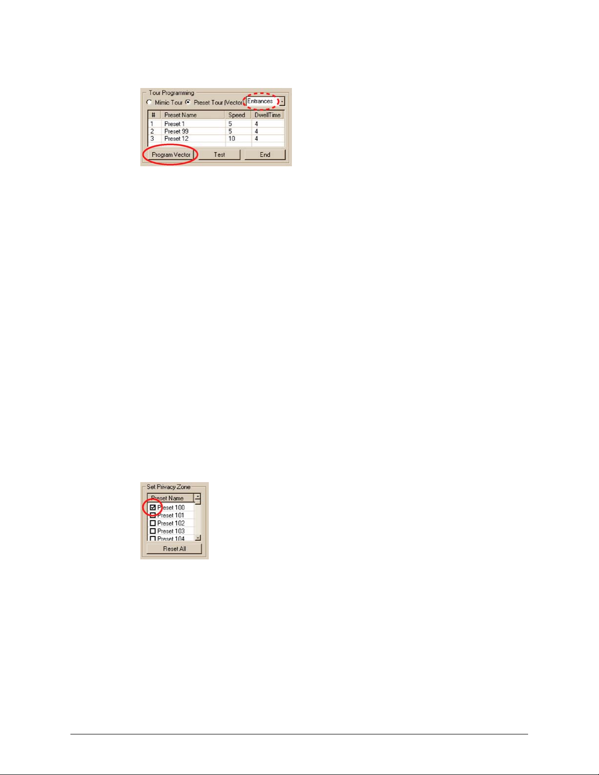
Pan, Tilt, and Zoom (PTZ) Setup
Fig. 6–12. Location of the Program Vector Button.
Testing a Preset Tour on a RapidDome Camera
1. While using View, select the site at which you have programmed a Preset Tour on a
RapidDome camera, as shown in procedure
RapidDome Camera.
To Setup a Tour of Presets on a
2. Run a
3. Select the dome camera that is programmed with a Preset Tour.
4. Click PTZ. Check if the Driver is “RapidDome/Orbiter”. If not, the wrong camera or site
5. In the “Tour Programming” section, click Preset Tour (Vector).
6. Select the preset tour that you plan to test. To do so, click the arrow button above Dwell
7. Click Test.
Maintenance Session; click the Video tab.
may have been selected in step 1 and the remaining steps in this procedure cannot be
used.
Time. A list appears, showing “Vector 1, Vector 2, Vector 3 …” by default. Click the name
that you need.
Privacy Zones for RapidDome
Fig. 6–13. Setting Up a Privacy Zone on a RapidDome PTZ Camera.
PTZ preset 100 to 127 can be toggled to not display or to display the video feed coming from the
RapidDome, when the dome is in the preset’s angle and zoom.
• Reset All. To cancel the privacy applied to presets, click Reset All. A confirmation dialog box
appears. Click Yes.
To Set a Privacy Zone
Select the box next to the preset name so that it shows a check-mark. See figure 6–13, above, and
figure
6–10–(4), on page 95. Remove the checkmark to enable Live and recoded video from that
PTZ preset.
98
Page 99

ACUIX Dome Camera
An ACUIX™ PTZ dome camera with Intellibus™ can be used and configured using Rapid Eye
View software. In preparation, installers have:
System Administrator’s Guide
• Set each ACUIX dome camera to their
• Set DIP switch 5–8 to ON, on each ACUIX dome camera. The Camera Address can then be set
using rotary switches (SW1 to SW4) on the PCB at the base of the dome.
• Connected the ACUIX dome cameras to a port on the Rapid Eye unit.
• Notified the Multi SA of the number of the port used on the Rapid Eye unit and the
Camera Address used for each ACUIX dome camera.
Intellibus mode (IBus).
Configuring the Intellibus Device for a Rapid Eye Unit
1. Assign the Intellibus device to the port used by the installers, by dragging its icon from
the Unassigned Devices to a "Port n". Figure
• Port "3" through "10". Select RS-485 on the Serial Devices tab.
• Port "1" or "2". Select RS-232. Use a hardware converter for RS-232/RS-485 on
these ports to translate communications to and from the
2. On the Serial Devices tab, select the values shown in table
Fig. 6–14. Communication Settings for Intellibus on the Serial Devices Tab.
6–14 shows the result when Port 4 is used.
ACUIX dome cameras.
6–3. See also figure 6–14.
Table 6–3 Communications for the Intellibus Device, and for each ACUIX Dome Camera
Communications Value
Baud Rate 38400
Stop Bits 1
Data Bits 8
Parity Bits none
Document K14392V1 Rev A 99
07/07
Page 100

Pan, Tilt, and Zoom (PTZ) Setup
To Configure an ACUIX Dome Camera for PTZ Use
1. Run a Maintenance Session.
2. Click the Video tab.
3. Click PTZ. For information about enabling and configuring a PTZ dome, see Video Tab
Settings for PTZ, on p. 86.
4. Select an
5. In Port Attributes, enter values for Baud Rate, Stop Bits, Data Bits and Parity Bits,
using those shown in table
ACUIX dome camera.
6–3.
6. For
7. Repeat steps 4 to 6 for each
Camera Address, do not use the same value for two ACUIX cameras that
share the same port.
ACUIX dome camera.
Discovery of ACUIX Dome Cameras
You have the option of running the discovery routine if domes were added or if the list of cameras
seems incomplete.
1. Run a
2. On the Serial Devices tab, click the port to which an Intellibus device is assigned.
3. Click Discover to update the table of
Maintenance Session.
ACUIX dome cameras.
Backing Up an ACUIX Configuration File to a PC
1. Run a Maintenance Session.
2. On the Serial Devices tab, click the port to which the Intellibus device is assigned.
3. Click Discover to update the table of
4. Select one
the table: click the checkbox in the Name column; see figure
5. Click Upload from Camera. The configuration file from each of the selected
dome cameras is copied to the Multi-Media DSP unit. A configuration file for an
dome camera includes: PTZ tours, PTZ presets, vectors and all other camera settings.
6. Click Manage Files. The Manage Files dialog box appears, showing the
camera configuration files (*.bin). See figure
configuration files is:
camera name_camera address_year_month_day_hour_minute_second.bin; for example:
"Lobby_4_2007_06_16_8_0_0.bin". Firmware files may also be listed and can be ignored
for this procedure; their extension is (*.ngd).
ACUIX dome camera or many. There is a shortcut to select all of the items in
ACUIX dome cameras.
6–14.
6–15. The naming convention of
ACUIX
ACUIX
ACUIX dome
100
7. Select a file.
8. Click Save. A standard Windows dialog appears, showing the drives and folders
available on the operator's PC. After selecting a drive, folder and filename, click OK.
9. In the Manage Files dialog box, click Close.
Commands in the Manage Files dialog box
This Manage Files dialog box shows only the files which are related to ACUIX dome cameras, from
among the files stored on the Rapid Eye unit. If there are no *.bin or *.ndg files, the Manage Files
dialog box displays an empty list.
 Loading...