

Page 1

ACUIX™
Fixed Dome
Installation Guide
Document 800-01605 – Rev A – 04/08
Page 2

Revisions
Issue Date Revisions
A 04/08 New document
Page 3

TM
ACUIX
Fixed Dome User Guide
Contents
1 Installing the Camera . . . . . . . . . . . . . . . . . . . . . . . . . . . . . . . . . . . . . . . . . 13
Related Documents . . . . . . . . . . . . . . . . . . . . . . . . . . . . . . . . . . . . . . . . . . . . 13
Models . . . . . . . . . . . . . . . . . . . . . . . . . . . . . . . . . . . . . . . . . . . . . . . . . . . 14
Overview of the Installation Process . . . . . . . . . . . . . . . . . . . . . . . . . . . . . . . . . . . . 15
Installing the Housing. . . . . . . . . . . . . . . . . . . . . . . . . . . . . . . . . . . . . . . 16
In-Ceiling (dropped) Housing Installation . . . . . . . . . . . . . . . . . . . . . . . 16
In-Ceiling Housing Installation . . . . . . . . . . . . . . . . . . . . . . . . . . . . . 17
Indoor Pendant Housing Installation . . . . . . . . . . . . . . . . . . . . . . . . .19
Connecting the Cables . . . . . . . . . . . . . . . . . . . . . . . . . . . . . . . . . . . . . . 20
Installing the Camera Assembly . . . . . . . . . . . . . . . . . . . . . . . . . . . . . . . . .21
Installing the Inner Dome Liner . . . . . . . . . . . . . . . . . . . . . . . . . . . . . . . . . .22
Installing the Lower Dome . . . . . . . . . . . . . . . . . . . . . . . . . . . . . . . . . . . . 23
In-Ceiling . . . . . . . . . . . . . . . . . . . . . . . . . . . . . . . . . . . . . . . .23
Pendant Lower Dome . . . . . . . . . . . . . . . . . . . . . . . . . . . . . . . . . 24
Routine Maintenance . . . . . . . . . . . . . . . . . . . . . . . . . . . . . . . . . . . . . . . . . . . . 24
2 Adjusting the Camera. . . . . . . . . . . . . . . . . . . . . . . . . . . . . . . . . . . . . . . . . 25
Adjusting the Camera Angle . . . . . . . . . . . . . . . . . . . . . . . . . . . . . . . . . . .25
Adjusting the Focal Length and Focusing the Lens . . . . . . . . . . . . . . . . . . . . . . . 27
Vari-focal Auto Iris Configuration (Color Cameras) . . . . . . . . . . . . . . . . . . . . . . . 27
Color Cameras . . . . . . . . . . . . . . . . . . . . . . . . . . . . . . . . . . . . . . . . . . 28
DIP Switch Settings . . . . . . . . . . . . . . . . . . . . . . . . . . . . . . . . . . 28
Wide Dynamic Range (WDR) Cameras . . . . . . . . . . . . . . . . . . . . . . . . . . . . .30
DIP Switch Settings . . . . . . . . . . . . . . . . . . . . . . . . . . . . . . . . . . 30
Adjusting the Line Lock (Vertical Phase) For External Sync Reference . . . . . . . . . . . . . 31
Adjusting the Backlight Compensation. . . . . . . . . . . . . . . . . . . . . . . . . . . . . . 31
Appendix A Solving Common Technical Issues . . . . . . . . . . . . . . . . . . . . . . . . . . . 33
Service . . . . . . . . . . . . . . . . . . . . . . . . . . . . . . . . . . . . . . . . . . . . . . . . . . . 33
Appendix B Cable Guidelines . . . . . . . . . . . . . . . . . . . . . . . . . . . . . . . . . . . . . 35
Appendix C Specifications . . . . . . . . . . . . . . . . . . . . . . . . . . . . . . . . . . . . . . 37
Rev A Document 800-01605
3
04/08
Page 4

Contents
Rev A Document 800-01605
4
04/08
Page 5

TM
ACUIX
Fixed Dome User Guide
Figures
Figure 1-1 Installation Components. . . . . . . . . . . . . . . . . . . . . . . . . . . . . . . . . . . . 16
Figure 1-2 Installing a Dropped Ceiling Housing . . . . . . . . . . . . . . . . . . . . . . . . . . . . . 16
Figure 1-3 In-Ceiling Hole Dimensions . . . . . . . . . . . . . . . . . . . . . . . . . . . . . . . . . . 18
Figure 1-4 In-Ceiling Housing Installation. . . . . . . . . . . . . . . . . . . . . . . . . . . . . . . . . 18
Figure 1-5 Spacing Wing Tabs . . . . . . . . . . . . . . . . . . . . . . . . . . . . . . . . . . . . . . 19
Figure 1-6 Pendant Dome Housing Installation. . . . . . . . . . . . . . . . . . . . . . . . . . . . . . 20
Figure 1-7 Wiring . . . . . . . . . . . . . . . . . . . . . . . . . . . . . . . . . . . . . . . . . . . . . 20
Figure 1-8 Power Cable Connection . . . . . . . . . . . . . . . . . . . . . . . . . . . . . . . . . . . 21
Figure 1-9 Camera Assembly . . . . . . . . . . . . . . . . . . . . . . . . . . . . . . . . . . . . . . . 22
Figure 1-10 Slide Inner Dome Liner into the Lower Dome . . . . . . . . . . . . . . . . . . . . . . . . . 22
Figure 1-11 Slide Lanyard into Clip. . . . . . . . . . . . . . . . . . . . . . . . . . . . . . . . . . . . . 23
Figure 1-12 In-Ceiling Lower Dome . . . . . . . . . . . . . . . . . . . . . . . . . . . . . . . . . . . . 23
Figure 1-13 Pendant Lower Dome Installation . . . . . . . . . . . . . . . . . . . . . . . . . . . . . . . 24
Figure 2-1 Recommended Camera Positions. . . . . . . . . . . . . . . . . . . . . . . . . . . . . . . 26
Figure 2-2 Gimbal Adjustment . . . . . . . . . . . . . . . . . . . . . . . . . . . . . . . . . . . . . . 26
Figure 2-3 Color Camera Switch Settings (Vari-focal Auto Iris Lens Shown). . . . . . . . . . . . . . . 28
Figure 2-4 WDR Camera Switch Settings . . . . . . . . . . . . . . . . . . . . . . . . . . . . . . . . . 30
Rev A Document 800-01605
5
04/08
Page 6

Figures
Rev A Document 800-01605
6
04/08
Page 7

TM
ACUIX
Fixed Dome User Guide
Tables
Table 1-1 ACUIX™Fixed Dome Housing Model Numbers . . . . . . . . . . . . . . . . . . . . . . . . 14
Table 1-2 ACUIX™Fixed Dome Lower Dome Model Numbers . . . . . . . . . . . . . . . . . . . . . . 14
Table 1-3 ACUIX™Fixed Dome Cameras and Lenses . . . . . . . . . . . . . . . . . . . . . . . . . . 15
Table 2-1 Color Camera DIP Switch Settings . . . . . . . . . . . . . . . . . . . . . . . . . . . . . . . 29
Table 2-2 White Balance Settings . . . . . . . . . . . . . . . . . . . . . . . . . . . . . . . . . . . . . 29
Table 2-3 Manual Shutter Speed Settings . . . . . . . . . . . . . . . . . . . . . . . . . . . . . . . . 29
Table 2-4 WDR Camera DIP Switch Settings . . . . . . . . . . . . . . . . . . . . . . . . . . . . . . . 31
Rev A Document 800-01605
7
04/08
Page 8

Tables
Rev A Document 800-01605
8
04/08
Page 9

FCC Compliance Statement
Information to the User: This equipment has been tested and found to comply with the limits for a Class B
digital device. Pursuant to Part 15 of the FCC Rules, these limits are designed to provide reasonable protection
against harmful interference in a residential installation. This equipment generates, uses, and can radiate radio
frequency energy and, if not installed and used in accordance with the instruction manual, may cause harmful
interference to radio communications. However, there is no guarantee that interference will not occur in a
particular installation.
If this equipment does cause harmful interference to radio or television reception, which can be determined by
turning the equipment off and on, the user is encouraged to try to correct the interference. For example, try
reorienting or relocating the receiving antenna, increasing the separation between the equipment and receiver,
or connecting the equipment to an outlet on a different circuit.
Caution Changes or modifications not expressly approved by the party responsible for
compliance could void the user’s authority to operate the equipment.
Canadian Compliance Statement
This Class B digital apparatus complies with Canadian ICES-003.
Cet appareil numérique de la classe B est conforme à la norme NMB-003 du Canada.
European Compliance Statement
This is a Class A product. In a domestic environment this product may cause radio interference in which case the user
may be required to take adequate measures.
Caution Users of the product are responsible for checking and complying with all federal, state and
local laws and statutes concerning the monitoring and recording of video and audio signals.
Honeywell Video Systems shall not be held responsible for the use of this product in violation
of current laws and statutes
Document 800-01605 Rev A 9
04/08
Page 10
Explanation of Graphical Objects
The lightning flash with arrowhead symbol within an equilateral triangle is intended to alert the user to the
presence of uninsulated "dangerous voltage" within the enclosure of the product that may be of sufficient
magnitude to constitute a risk of electric shock to the person.
The exclamation point within an equilateral triangle is intended to alert the user to the presence of
important operating and maintenance servicing instructions in the literature accompany the product.
Important Safety Instructions
READ INSTRUCTIONS - All safety and operating instructions should be read before the unit is operated.
1. RETAIN INSTRUCTIONS - The safety and operating instructions should be retained for future reference.
2. HEED WARNINGS - All warnings on the unit and in the operating instructions should be adhered to.
3. FOLLOW INSTRUCTIONS - All operating and use instructions should be followed.
4. CLEANING - Unplug the unit from the outlet before cleaning. Do not use liquid cleaners or aerosol cleaners. Use
a damp cloth for cleaning.
5. ATTACHMENTS - Do not use attachments not recommended by the product manufacturer as they may result in
the risk of fire, electric shock, or injury to persons.
6. WATER AND MOISTURE - Do not use this unit near water or in an unprotected outdoor installation, or any area
classified as a wet location.
7. ACCESSORIES - Only use accessories specified by the manufacturer. Do not place this product on an unstable
cart, stand, tripod, bracket, or table. The product may fall, causing serious injury to a child or adult and serious
damage to the equipment. Use only with a cart, stand, tripod, bracket, or table recommended by the
manufacturer, or sold with the product. Any mounting of the product should follow the manufacturer's
instructions and should use a mounting accessory recommended by the manufacturer. Wall or shelf mounting
should follow the manufacturer's instructions and should use a mounting kit approved by the manufacturer.
8. A product and cart combination should be moved with care. Quick stops, excessive force, and uneven surfaces
may cause the product and cart combination to overturn.
9. POWER SOURCES - This product should be operated only from the type of power source indicated on the
marking label. If you are not sure of the type of power supplied to your facility, consult your product dealer or
local power company.
10. OVERLOADING - Do not overload outlets and extension cords as this can result in a risk of fire or electric shock.
11. POWER-CORD PROTECTION - Power supply cords should be routed so that they are not likely to be walked on
or pinched by items placed upon or against them, paying particular attention to cords, plugs, and convenience
receptacles.
10
Page 11

12. SERVICING - Do not attempt to service this unit yourself as opening or removing covers may expose you to
dangerous voltage or other hazards. Refer all servicing to qualified service personnel.
13. DAMAGE REQUIRING SERVICE - Unplug the unit from the outlet and refer servicing to qualified service
personnel under the following conditions:
a. When the power-supply cord or plug is damaged.
b. If liquid has been spilled, or objects have fallen into the unit.
c. If the unit has been exposed to rain or moisture.
d. If the unit does not operate normally by following the operating instructions. Adjust only those controls that
are covered by the operating instructions as an improper adjustment of other controls may result in damage
and will often require extensive work by a qualified technician to restore the unit to its normal operation.
e. If the unit has been dropped or the enclosure has been damaged.
f. When the unit exhibits a distinct change in performance - this indicates a need for service.
14. REPLACEMENT PARTS - When replacement parts are required, be sure the service technician has used
replacement parts specified by the manufacturer or have the same characteristics as the original part.
Unauthorized substitutions may result in fire, electric shock or other hazards.
15. SAFETY CHECK - Upon completion of any service or repairs to this unit, ask the service technician to perform
safety checks to determine that the unit is in proper operating condition.
16. LIGHTNING AND POWER LINE SURGES - For added protection of this unit when it is left unattended and unused
for long periods of time, unplug it from the wall outlet and disconnect the cable system. This will prevent damage
to the unit due to lightning and power-line surges.
17. HEAT - The product should be situated away from heat sources such as radiators, heat registers, stoves, or other
products (including amplifiers) that produce heat.
18. INSTALLATION - Install in accordance with the manufacturer’s instructions. Do not install the unit in an extremely
hot or humid location, or in a place subject to dust or mechanical vibration. The unit is not designed to be
waterproof. Exposure to rain or water may damage the unit.
Prior to installation and use of this product, please observe the following cautions and warnings.
Document 800-01605 Rev A 11
04/08
Page 12
Caution
CAUTION
RISK OF ELECTRIC SHOCK
DO NO T OPEN
CAUTION: TO REDUCE THE RISK OF ELECTRIC SHOCK,
DO NOT REMOVE COVER (OR BACK).
NO USER-SERVICEABLE PARTS INSIDE.
REFER SERVICING TO QUALIFIED SERVICE PERSONNEL.
Warnings
WARNING: Installation and servicing must be performed by qualified personnel in accordance with
current IEE wiring regulations.
WARNING: The PSU must be wired to a double pole fuse spur with 3mm separation. The 3A fuse spur
must be located close to the PSU.
WARNING: Using replacement parts or accessories other than the original manufacturers may invalidate
the warranty.
WARNING: To prevent injury, this apparatus must be securely attached to the wall/ceiling in accordance
with the installation instructions.
12
Page 13

Installing the Camera
This guide covers how to install the ACUIX™fixed dome camera. It includes instructions
to install the housing mount, how to mount the camera in the housing, how to connect the
wiring, and how to adjust the image.
The ACUIX™ product line offers housings for indoor applications. The indoor application
features a pendant housing for wall mounting and an indoor in-ceiling housing. There are
also adapters available for corner and pole mounting.
This guide provides instructions for mounting the different types of housings. Each
housing contains an interface board that provides wiring for video on coax or unshielded
twisted pair, and control data on shielded or unshielded twisted pair (RS485) or over
coax.
1
Related Documents
For more information about topics that are relevant to the subject of this guide, see the
documents listed below:
Document title Part number
HDXWM1 Decorative Wall Mount Install Guide 900.0868
HDCM1 Indoor Pendant Mount Install Guide 900.0869
Document 800-01605 Rev A 13
04/08
Page 14

Installing the Camera
Models
Refer to the following table for the ACUIX™fixed dome model numbers.
Table 1-1 ACUIX™Fixed Dome Housing Model Numbers
Model Number Description
HDH1B FG, HSG, HDX FIXED, PNDT, COAX, BLACK
HDH1D FG, HSG, HDX FIXED, IN CEILING, COAX
HDH1P FG, HSG, HDX FIXED, PNDT, COAX, WHITE
HDH2B FG, HSG, HDX FIXED, PNDT, UTP (Unshielded Twisted Pair),
BLACK
HDH2D FG, HSG, HDX FIXED, IN CEILING, UTP
HDH2P FG, HSG, HDX FIXED, PNDT, UTP, WHITE
Table 1-2 ACUIX™Fixed Dome Lower Dome Model Numbers
Model Number Description
HDB00D0CB FG, LWR DOME, IN CEILING, CLEAR, BLACK TRIM
HDB00D0CW FG, LWR DOME, IN CEILING, CLEAR, WHITE TRIM
HDB00D0GB FG, LWR DOME, IN CEILING, GOLD, BLACK TRIM
HDB00D0GW FG, LWR DOME, IN CEILING, GOLD, WHITE TRIM
HDB00D0KB FG, LWR DOME, IN CEILING, CHROME, BLACK TRIM
HDB00D0KW FG, LWR DOME, IN CEILING, CHROME, WHITE TRIM
HDB00D0SB FG, LWR DOME, IN CEILING, SMOKED, BLACK TRIM
HDB00D0SW FG, LWR DOME, IN CEILING, SMOKED, WHITE TRIM
HDB00P0CB FG, LWR DOME, PNDT, CLEAR, BLACK TRIM
HDB00P0CW FG, LWR DOME, PNDT, CLEAR, WHITE TRIM
HDB00P0GB FG, LWR DOME, PNDT, GOLD, BLACK TRIM
HDB00P0GW FG, LWR DOME, PNDT, GOLD, WHITE TRIM
HDB00P0SB FG, LWR DOME, PNDT, SMOKED, BLACK TRIM
HDB00P0SW FG, LWR DOME, PNDT, SMOKED, WHITE TRIM
14
Page 15

Table 1-3 ACUIX™Fixed Dome Cameras and Lenses
Model Number Description
HDC1AN Color, 480TVL, NTSC with 5-50mm MI (Manual Iris) lens
HDC1BN WDR, 480TVL, NTSC with 5-50mm MI lens
HDC2AN Color, 480TVL, NTSC with 5-50mm AI (Automatic Iris) lens
HDC2BN WDR, 480TVL, NTSC with 5-50mm AI lens
Overview of the Installation Process
Task See section
ACUIX
TM
Fixed Dome User Guide
1. Install the housing in a ceiling or wall. See “Installing the Housing” on page 16.
2. Mount the ACUIX™to a ceiling or wall. See “Connecting the Cables” on page 20.
3. Connect the cable to the camera board. See “Connecting the Cables” on page 20.
4. Secure the gimbal into the
ACUIX™base.
5. Adjust the camera settings. See “Adjusting the Camera” on page 25.
6. Secure the cover. See “Installing the Lower Dome” on
See “Installing the Camera Assembly” on
page 21.
page 23.
Document 800-01605 Rev A 15
04/08
Page 16

Installing the Camera
Figure 1-1 Installation Components
In-Ceiling Pendant
Base
Gimbal
Inner Dome Liner
Dome Cover
Installing the Housing
In-Ceiling (dropped) Housing Installation
WARNING! Installation must be performed by qualified technical
Perform the following steps to install a dropped ceiling housing (see Figure 1-2):
Figure 1-2 Installing a Dropped Ceiling Housing
Dropped Ceiling Plate
personnel and must be in accordance with all national and
local mechanical and electrical codes.
Housing
Field wiring access hole
Drywall
ceiling
16
Lower dome mounting
posts (3 places)
Attach lanyard to
lower dome
Page 17

TM
ACUIX
1. Select the location of the housing. Each ACUIX™ Fixed requires either a 17 to 28
VAC or an 11 to 16 VDC power source measured at the housing. Each ACUIX™
Fixed has a power consumption of 3.5W for the color cameras or 4.5W for the WDR
cameras. Ensure a 24 VAC/12 VDC @ 0.2A power source is available. See
Appendix B, Cable Guidelines on page 35 for maximum wiring distances to the
dome.
2. Remove the ceiling panel at the dome location.
3. Place the ceiling tile on the dropped ceiling plate. Trim the ceiling tile so you can
press the ceiling tile into the dropped ceiling plate.
4. Cut a hole in the ceiling tile flush with the hole in the center of the plate.
5. If necessary, secure a safety cable (supplied by the installer) to a building support
structure. Honeywell recommends using a 3/32” plastic coated aircraft cable.
6. Insert the housing in the ceiling
a. Adjust the turning screws on the wing tabs to ensure the space between the
wing tabs and housing flange is greater than the thickness of the ceiling.
b. Position the wing tabs flat against the housing. Insert the housing through the
hole in the ceiling tile. Using a Phillips screwdriver, turn the two screws in the
housing clockwise to rotate the tabs out and tighten the tabs against the ceiling
tile. The recommended maximum torque is 1–1.25 N-m or 0.74–0.92 lbf-ft or
8.85–11.06 lbf-in.
c. Insert the housing through the hole in the ceiling, ensuring the wing tabs are flat
against the housing. The recommended maximum torque is 1–1.25 N-m
7. See Connecting the Cables on page 20 for information on connecting the field
wiring to the interface board in the housing.
8. See Installing the Camera Assembly on page 21 for information on installing the
camera assembly and Installing the Lower Dome on page 23 for information on
installing the lower dome.
Fixed Dome User Guide
In-Ceiling Housing Installation
WARNING! Installation must be performed by qualified technical
personnel and must be in accordance with all national and
local mechanical and electrical codes.
Perform the following steps to install an ACUIX™in-ceiling housing:
1. Select the location of the housing. Each ACUIX™ Fixed requires either a 17 to 28
VAC or an 11 to 16 VDC power source measured at the housing. Each ACUIX™
Fixed has a power consumption of 3.5W for the color cameras or 4.5W for the WDR
cameras. Ensure a 24 VAC/12 VDC @ 0.2A power source is available. See
Appendix B, Cable Guidelines on page 35 for maximum wiring distances to the
dome.
2. Cut a 7/15-16” (201.2 mm) diameter hole in the ceiling.
Document 800-01605 Rev A 17
04/08
Page 18

Installing the Camera
Figure 1-3 In-Ceiling Hole Dimensions
7-15/16” (201.2 mm)
3. If the ceiling is drywall or plaster, Honeywell Video Systems recommends sealing
the entire perimeter of the ceiling cut-out with tape or a plastic channel (provided by
the installer). This prevents dust and material from dropping from the ceiling.
4. If required, secure a safety cable (supplied by the
installer) to a building support structure. Honeywell
recommends using a 3/32” plastic coated aircraft cable.
Attach the safety cable (from the building support
structure) to the housing by:
a. Threading the safety cable through a looping
sleeve,
b. Through the lanyard clip (see Figure 1-4),
c. Back through the looping sleeve, and then
d. Crimping the looping sleeve to secure the safety
cable.
5. Insert the housing in the ceiling.
Attach to building
structure
Looping
sleeves (2)
Attach to lanyard
clip
18
Figure 1-4 In-Ceiling Housing Installation
Cable entry hole
Lanyard clip
Wing screws
a. Ensure that the space between the wing tabs on the housing and the housing
flange is greater than the thickness of the ceiling tile. Adjustments are made by
turning the screws on the wing tabs; clockwise decreases the space between
the tab and the housing flange and counterclockwise increases the space
between the tab and the housing flange. Make sure the wing tabs on the
housing are staggered so the tabs are not at the same height.
Page 19

TM
ACUIX
Figure 1-5 Spacing Wing Tabs
b. Position the wing tabs flat against the housing. Insert the housing through the
hole in the ceiling (some jostling is required). Using a Phillips screwdriver, turn
the two screws in the housing clockwise to rotate the tabs out and tighten the
tabs against the ceiling. The recommended maximum torque is 1–1.25 N-m
(Newton meters) or 0.74–0.92 lbf-ft (pound-force-foot) or 8.85–11.06 lbf-in
(pound-force-inch).
6. Refer to Connecting the Cables on page 20 for information on connecting the field
wiring to the interface board in the housing.
7. See Installing the Camera Assembly on page 21 for information on installing the
camera assembly and Installing the Lower Dome on page 23 for information on
installing the lower dome.
Fixed Dome User Guide
Indoor Pendant Housing Installation
WARNING! Installation must be performed by qualified technical
personnel and must be in accordance with all national and
local mechanical and electrical codes.
Perform the following steps to install an ACUIX™pendant housing on a Honeywell Video
Systems indoor wall dome mount or ceiling dome mount. See Figure 1-6.
1. Select the location of the housing. Each ACUIX™ Fixed requires either a 17 to 28
VAC or an 11 to 16 VDC power source measured at the housing. Each ACUIX™
Fixed has a power consumption of 3.5W for the color cameras or 4.5W for the WDR
cameras. Ensure a 24 VAC/12 VDC @ 0.2A power source is available. See
Appendix B, Cable Guidelines on page 35 for maximum wiring distances to the
dome.
2. Install the mount using the instructions provided with your specific mount.
3. Run the field wiring (control data, video, power, and alarm) through the mount. The
wiring must extend at least one foot (0.3 m) past the pipe for wiring purposes. See
Cable Guidelines on page 35 for detailed wiring information.
4. Locate the pendant housing.
Document 800-01605 Rev A 19
04/08
Page 20
Installing the Camera
Figure 1-6 Pendant Dome Housing Installation
1.5” NPT threaded nipple
Route field wiring
from mount
a. Insert the field wiring (data, power, video, and alarm) from the mount through
the threaded nipple on the pendant housing.
b. Carefully thread the housing into the mount.
5. See Power Cable Connection on page 21 for information on connecting the field
wiring to the terminal strips on the interface board in the housing.
6. See Installing the Camera Assembly on page 21 for information on installing the
camera assembly and Installing the Lower Dome on page 23 for information on
installing the lower dome.
Connecting the Cables
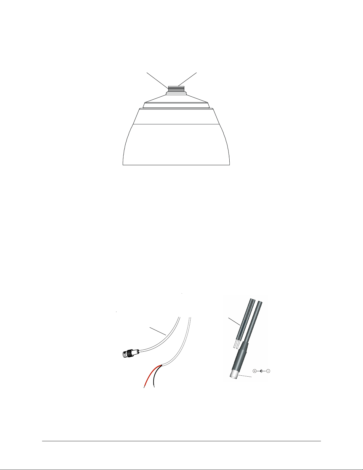
1. Follow Figure 1-7 for the wiring connection.
Figure 1-7 Wiring
Video: female BNC
red +
connect to red +
2. Connect the power/video cable from the gimbal assembly to the camera board (see
Figure 1-8).
Coaxial Cables UTP Cables
Video: Unshielded
Twisted Pair wire
Power
black connect to ground
Power: 2.1 mm
male jack center
20
Page 21

TM
ACUIX
Fixed Dome User Guide
Note For secure installations, surface-mounted cables should be protected by
plastic or metal cable covers.
Figure 1-8 Power Cable Connection
Gimbal assembly
Power/video
Installing the Camera Assembly
To install the camera assembly into the ACUIX™base:
1. Loosen all three thumb nuts on the camera chassis (see Figure 1-9).
2. Slide the gimbal ring under the two tabs on either side of the thumb nuts on each
bracket (total of 6 tabs).
3. Adjust the camera position. See “Adjusting the Camera” on page 25.
4. Tighten all three thumb nuts to secure the camera assembly.
Make sure that the camera DIP switches are on the top of the lens mount when the
ACUIX™is mounted on the wall or ceiling.
Power supply board
Document 800-01605 Rev A 21
04/08
Page 22

Installing the Camera
Gimbal ring
Figure 1-9 Camera Assembly
Bracket tabs (x2)
Gimbal chassis
Note After installing the camera assembly, you need to adjust and focus the
camera before installing the lower dome to complete the installation process.
To adjust and focus the camera, see Adjusting the Camera on page 25.
Note The lower dome might affect the focus. After installing the lower dome, you
should check the focus. If the focus needs adjustment, uninstall the lower
dome, make the adjustments, reinstall the lower dome, and then recheck the
focus.
Installing the Inner Dome Liner
Loosen thumb
nuts (x3)
22
1
1. Slide the inner dome liner on an angle into the lower dome so that one side fits
snugly into place.
Figure 1-10 Slide Inner Dome Liner into the Lower Dome
Inner Dome Liner
1
Inner Dome Liner
2
Lower Dome
In-Ceiling
Pendant
2. Push down on the other side until it snaps into place.
2
Page 23

Installing the Lower Dome
In-Ceiling
1. Slide the end of the lanyard into the round opening on the lanyard clip and slide
towards the narrow end until the lanyard is secure.
Figure 1-11 Slide Lanyard into Clip
ACUIX
TM
Fixed Dome User Guide
Mounting brackets (3 places)
2. Align the lower dome with the three mounting posts in the housing and push the
lower dome until it is snug with the housing.
Figure 1-12 In-Ceiling Lower Dome
3
2
2
3. Twist to lock the lower dome brackets over the mounting posts.
Document 800-01605 Rev A 23
04/08
Page 24

Installing the Camera
Hook lanyard from
lower dome to retaining
bracket in housing
Pendant Lower Dome
1. Hook the lanyard attached to the lower dome onto the retaining bracket in the
housing.
Figure 1-13 Pendant Lower Dome Installation
Two screws
Trim ring
2. Ensure the trim ring is in place around the lower dome.
3. Press the lower dome into the housing.
4. Secure the lower dome to the housing by installing the two screws provided with the
lower dome.
Routine Maintenance
Use regular liquid cleaners to remove most dirt and grime from the ACUIX™enclosure.
Caution Do not use harsh or abrasive cleaners which can scratch the
polycarbonate or acrylic dome and reduce visibility from the
camera.
24
Page 25

Adjusting the Camera
Caution In certain camera positions, components on the rear camera board
can come in contact with parts of the gimbal, which can cause
damage to the camera board.
Note You cannot adjust the camera with the lower dome installed. But the lower
dome must be installed to check the adjustments. You may have to install and
remove the lower dome several times while adjusting the camera.
Adjusting the Camera Angle
2
To adjust the ACUIX™Camera angle:
1. Remove the lower dome if it has been installed.
2. Connect the service monitor cable (supplied) to the video monitor output (see
Figure 2-3 if you have a color camera and Figure 2-4 if you have a WDR camera) so
you can view the image from the camera.
3. Apply 11-16 VDC or 24 VAC power to the camera and monitor the video signal.
4. Adjust the camera carrier to the desired view by moving the gimbal in the V-shaped
slot (see Figure 2-1).
a. Loosen the two Phillips screws that keep the camera carrier in place.
b. Move the camera carrier into the desired position.
c. Tighten the two Phillips screws.
Document 800-01605 Rev A 25
04/08
Page 26

Adjusting the Camera
Figure 2-1 Recommended Camera Positions
Use these alternate
positions when
your desired field of
view (FOV) is a
steep angle or
parallel to a wall or
ceiling.
5. Adjust the camera to the desired view.
a. Loosen as many screws and thumb nuts that lock the gimbal assembly in place
as necessary to adjust the camera position (see Figure 2-2).
b. Adjust the pan, tilt, and horizontal rotation.
c. Tighten the screws and thumb nuts to lock the gimbal assembly in place.
Figure 2-2 Gimbal Adjustment
C
Tilt rotation
A
Recommended
camera
positions
Roll rotation
B
B
26
Legend
A = Roll rotation
B = Pan rotation
C = Tilt rotation
A
B
B
V slot
C
Pan rotation
Page 27

ACUIX
Adjusting the Focal Length and Focusing the Lens
1. Remove the lower dome if it has been installed.
2. Loosen the top locking screw and then rotate the barrel to adjust the focal length. See
Figure 2-3 for color cameras. See Figure 2-4 for WDR cameras.
3. Loosen and then move the bottom locking screw (closest to the camera board) to
adjust the focus. See Figure 2-3 for color cameras. See Figure 2-4 for WDR cameras.
4. Install the lower dome (see Installing the Lower Dome on page 23 ).
5. Check the picture. If the focus is clear, go to Vari-focal Auto Iris Configuration (Color
Cameras) on page 27. If the focus is not clear, remove the lower dome, then go back
to step 2 and repeat until you are satisfied with the picture clarity. You may have to
readjust the camera angle.
Vari-focal Auto Iris Configuration (Color Cameras)
To configure the Vari-focal Auto Iris settings (adjust the iris), see Figure 2-3. Use the
potentiometer, located on the lower left corner on the top or front of the camera board
on color cameras, to regulate to regulate the Auto Iris lens.
1. Remove the lower dome if it has been installed.
2. Set the DIP switches. See the section for your camera type for the DIP switch
functions and adjustment methods (Color Cameras on page 28 for color cameras and
Wide Dynamic Range (WDR) Cameras on page 30 for wide dynamic range cameras) .
3. Disconnect service monitor when you are finished adjusting the camera.
4. Install the lower dome.
TM
Fixed Dome User Guide
Document 800-01605 Rev A 27
04/08
Page 28

Adjusting the Camera
Color Cameras
DIP Switch Settings
Figure 2-3 Color Camera Switch Settings (Vari-focal Auto Iris Lens Shown)
* N/U = Not used.
Leave in Off position.
Note You may find it helpful to use the
Allen key (supplied) to access the
DIP switches.
GAMMAAEFLON
BLC
10 9 8 7 6 5 4 3 2 1
DC Iris
adjust
IRIS
NU*
AGC MAX
AWB1
AWB2
Line-lock phase
adjustment pot
AWB3
Push lock
Video monitor
output
Top locking screw
adjusts focal length.
Bottom locking
screw adjusts focus.
Factory (default) settings
Vari-focal Auto Iris
10 9 8 7 6 5 4 3 2 1
= ON (up)
= OFF (down)
28
Page 29

ACUIX
Adjustment Method
Table 2-1 Color Camera DIP Switch Settings
Switch
no.
10 GAMMA Off (0.45) On (1.0)
9 AE (Automatic
8 FLON (Flicker Less) Off On
7BLC (Backlight
6 IRIS Control Electronic IRIS Auto IRIS
5 Not used Not used Not used
4 AGC 4 dB 26 dB
Function Off On
Off On (see Manually Setting the
Exposure)
Off On (Center window)
Compensation)
Shutter Speed)
White Balance Adjustment Method
TM
Fixed Dome User Guide
Table 2-2 White Balance Settings
Symbol SW3/AWB1 SW2AWB2 SW1AWB3
AWB Off Off Off
ATW Off On Off
Push lock Off On On *
Indoor (3200° K) On Off On
Outdoor (6500° K) On On On
* To manually set Push lock feature: place a white background in
front of camera and press “Push lock” switch.
Manually Setting the Shutter Speed
To manually set the shutter speed, turn switch #9 to the ON position; then set switch #6,
#7, and #8 for the desired shutter speed (see Figure 2-3).
Table 2-3 Manual Shutter Speed Settings
Shutter
speed(s)
1/50 (PAL)
1/60 (NTSC)
1/100 (PAL)
1/120 (NTSC)
1/250 Off Off Off On
1/500 Off Off On On
1/1000 On On Off On
SW6
IRIS
Off On Off On
OffOnOnOn
SW7
BLC
SW8
FLON
SW9
AE
Document 800-01605 Rev A 29
04/08
Page 30

Adjusting the Camera
Table 2-3 Manual Shutter Speed Settings
Shutter
speed(s)
SW6
IRIS
SW7
BLC
SW8
FLON
SW9
AE
1/2000 On On On On
1/4000 On Off Off On
1/10000 On Off On On
Note FLON, BLC, and IRIS can be set when switch #9 is set to the OFF position.
Caution Before you adjust the shutter speed, it is important that you
understand how the settings can affect the scene detail.
Wide Dynamic Range (WDR) Cameras
DIP Switch Settings
Figure 2-4 WDR Camera Switch Settings
Line-lock
adjustment
EE/DC IRIS
AWB/ATW
WDR
AGC
MIRROR
Note You may find it helpful to use the
Allen key (supplied) to access the
DIP switches.
Top locking
screw to set
focus
Bottom locking
screw to set
focal length
Factory (default)
30
Auto Iris level adjustment. If
necessary, turn clockwise to
increase brightness level.
Video monitor
output
= ON (up)
= OFF (down)
Page 31

TM
ACUIX
Note The Wide Dynamic Range camera has been designed for the best wide
dynamic performance and can only be used with Vari-focal Auto Iris lens.
Fixed Dome User Guide
Adjustment Method
Table 2-4 WDR Camera DIP Switch Settings
Switch no. Function Off On
1 EE/DC IRIS EE DC IRIS
2AWB/ATW AWBATW
3 WDR (Wide Dynamic Range) Off On
4AGC OffOn
5MIRROR OffOn
Adjusting the Line Lock (Vertical Phase) For External Sync Reference
Phase adjustment may be necessary in multiple camera installations to prevent picture roll
when switching between cameras. To adjust the vertical phase while switching between
two cameras, turn the line-lock adjustment pot on one camera until there is no vertical roll.
See Figure 2-3 for color cameras. The wide dynamic range (WDR) cameras use the
line-lock adjustment buttons to adjust the vertical phase (see Figure 2-4).
Note If the phase cannot be adjusted to prevent picture roll, reverse the line-lock
input polarity by switching the power wires.
Adjusting the Backlight Compensation
The backlight compensation (BLC) adjusts the electronic shutter speed of the camera
based on the light levels in specific areas of the scene. This adjustment provides better
image quality for scenes that are unevenly lit.
To adjust the BLC, set the BLC switch to ON. See Figure 2-3 for color cameras. Center
window weighted.
Document 800-01605 Rev A 31
04/08
Page 32

Adjusting the Camera
32
Page 33

Solving Common Technical Issues
No video
❐ Check that the power supply voltage is within the operating specifications for
your camera model (see Specifications for details).
❐ Connect a video monitor directly to the ACUIX™video output cable to eliminate
video problems that could be caused by other equipment such as video
switches.
❐ Check the video connections to the monitor or CCTV system.
❐ Check for a loose connection at the video camera.
❐ Ensure that lens cap has been removed.
Fuzzy video
❐ Check the video ground connections.
❐ Check for ground loops.
❐ Check camera focus.
A
Service
Call Honeywell Customer Service for additional assistance (see Service for contact
numbers).
Subject to the terms and conditions listed on the Product Warranty Card, during the
warranty period Honeywell will repair or replace, at its sole option, free of charge, any
defective products returned prepaid.
In the event you have a problem with any Honeywell product, please call Customer
Service for assistance or to request a Return Merchandise Authorization (RMA)
number.
In the U.S.A. and Canada, call 1.800.796.2288.
Be sure to have the model number, serial number, and the nature of the problem available
for the technical service representative.
Document 800-01605 Rev A 33
04/08
Page 34

Solving Common Technical Issues
Prior authorization must be obtained for all returns, exchanges, or credits. Items shipped
to Honeywell without a clearly identified Return Merchandise Authorization (RMA)
number may be refused.
34
Page 35

Cable Guidelines
Power supply cable maximum length (feet/meters)
Total
load
Cameras with AC/DC power supplies
3.5 W 15 VDC 180/55 290/88 730/220 1170/352
3.5 W 24 VAC 470/143 760/232 1926/587 3065/934
Note Calculations are based on an unregulated linear power supply which
Note Calculations are based on a 15VDC power supply to allow for longer
Video cable maximum length (feet/meters)
Maximum length (feet/meters) 750/229 1500/457 2000/610
* Copper clad steel core, 95% braided shield
We recommend these NVT video transceivers (sold separately by NVT Inc.):
NV-212A (500 ft/152 m—26 Ω)**
NV-213A/A-M (1000 ft/305 m—52 Ω)**
NV-652R, NV-862R or NV-1662R (3000 ft/914 m—163 Ω)**
** Distances have been calculated using 24 AWG Twisted Pair wire.
Note We recommend that you measure the wire distance to ensure the
AWG 250/76 500/152 1000/305 1500/457 2000/610
18 3 Ω 6 Ω 13 Ω 19 Ω 26 Ω
20 5 Ω 10 Ω 20 Ω 30 Ω 40 Ω
22 8 Ω 17 Ω 33 Ω 48 Ω 66 Ω
24 13 Ω 26 Ω 52 Ω 78 Ω 108 Ω
Note Use point-to-point Unshielded Twisted Pair wire only.
Power
supply
would be the worst case. Using a regulated or switching power
supply can increase the cable distance. We recommend using a CSA
Certified/UL listed Class 2
electrical safety standards.
cable runs.
Cable type RG-59 RG-6 RG-11
Wire gauge 23 AWG* 18 AWG* 14 AWG*
capability of the twisted pair product is not exceeded. Use an
ohmmeter to measure wire resistance by shorting the two conductors
together at the far end, then measure the loop resistance out and
back. Compare to the table below.
Maximum length (feet/meters)
B
Wire gauge
24 AWG 22 AWG 18 AWG 16 AWG
power adapter to ensure compliance with
Document 800-01605 Rev A 35
04/08
Page 36

Cable Guidelines
36
Page 37

C
Specifications
Video specifications High RES
Pickup device: 1/3 in. CCD
Electronic iris: 1/60 to 1/100,000 second
Surge protection: 1.5 kW transient
Video output impedance: 1 Vp-p @ 75 Ohms
Video signal:
Color Standard NTSC
Resolution: High RES
Color, True Day/Night 480 TV lines
Wide Dynamic, Wide
Dynamic True Day/Night 480 TV lines
Signal to noise ratio
(Color cameras): Better than 51 dB
Dynamic range (Wide
Dynamic camera only): Better than 52 dB
Light sensitivity:
Color 0.7 lux @ F1.3
True Day/Night 0.3 lux @ F1.3
Wide Dynamic 1.0 lux @ F1.3
Wide Dynamic True
Day/Night 0.4 lux @ F1.3
White Balance:
Color, True Day/Night AWB/ATW/Indoor (3200°K), Outdoor (6500°K), Push Lock
BLC Center window weighted on/off, switchable
Lens Type 5 to 50 mm (F1.3) Vari-focal Auto Iris CS Mount
Angle of View Tele: 6.9°(D), 5.5°(H), 4.1°(V)
Wide: 63°(D), 48°(H), 35°(V)
Power requirements
Input voltage: 24 VAC/12 VDC
Input range: 17 to 28 VAC, 11 to 16 VDC
Power consumption:
Color 3.5 W (max)
True Day/Night 3.5 W (max)
Wide Dynamic, Wide
Dynamic True Day/Night 4.5 W (max)
Document 800-01605 Rev A 37
04/08
Page 38

Specifications
Operating environment
Temperature:
Operating -13°F to 122°F (-25°C to 50°C)
Storage -31°F to 140°F (-35°C to 50°C)
Humidity: 0 to 95% RH non-condensing
Size and weight
Dimensions 7.5 in. x 5.3 in. (191 mm x 134.5 mm
Size 2.0 lb (0.9 kg)
Regulatory
Emissions FCC, CE (EN55013)
Immunity CE (EN50130-4)
Safety EU: 73/23/EEC LVD, UL2044
Note Specifications apply to all camera models, unless noted otherwise.
38
Page 39

Page 40

Honeywell Video Systems (Head Office)
2700 Blankenbaker Pkwy, Suite 150
Louisville, KY 40299, USA
www.honeywellvideo.com
℡ +1.800.796.2288
Honeywell Video Systems Northern Europe
Netwerk 121
1446 WV Purmerend, The Netherlands
www.honeywell.com/security/nl
℡ +31.299.410.200
Honeywell Security Australia Pty Ltd.
Unit 5, Riverside Centre, 24-28 River Road West
Parramatta, NSW 2150, Australia
www.honeywellsecurity.com/au
℡ +61.2.8837.9300
Honeywell Security Asia Pacific
33/F Tower A, City Center, 100 Zun Yi Road
Shanghai 200051, China
www.asia.security.honeywell.com
℡ +86 21.2527.4568
Honeywell Security Asia
Flat A, 16/F, CDW Building, 388 Castle Peak Road
Tsuen Wan, N.T., Hong Kong
www.asia.security.honeywell.com
℡ +852.2405.2323
Honeywell Security France
Parc Gutenberg, 8, Voie La Cardon
91120, Palaiseau, France
www.honeywell.com/security/fr
℡ +33.01.64.53.80.40
Honeywell Security Italia SpA
Via della Resistenza 53/59
20090 Buccinasco
Milan, Italy
www.honeywell.com/security/it
℡ +39.02.48880551
Honeywell Systems Group
Aston Fields Road, Whitehouse Ind Est
Runcorn, Cheshire, WA7 3DL, UK
www.honeywell.com/security/uk
℡ +44 (0)1928 756999
Honeywell Security South Africa
Unit 6 Galaxy Park, 17 Galaxy Avenue
Linbro Park, P.O. Box 59904
2100 Kengray, Johannesburg, South Africa
www.honeywell.co.za
℡ +27.11.574.2500
Honeywell Security Deutschland
Johannes-Mauthe-Straße 14
D-72458 Albstadt, Germany
www.security.honeywell.com/de
℡ +49.74 31.8 01.0
Honeywell Security Poland
Chmielewskiego 22a, 70-028
Szczecin, Polska
www.ultrak.pl
℡ +48.91.485.40.60
Honeywell Security Czech Republic
Havránkova 33, Brno
Dolní Heršpice, 619 00, Czech Republic
www.olympo.cz
℡ +420.543.558.111
Honeywell Security España
Mijancas 1. 3
a
Planta
P.Ind. Las Mercedes
28022 Madrid, Spain
www.honeywell.com/security/es
Honeywell Security Slovakia Republic
Vajnorská 142, 83104 Bratislava
Slovakia
www.olympo.sk
℡ +421.2.444.54.660
℡ +34.902. 667.800
www.honeywellvideo.com
+1.800.796.CCTV (North America only)
HVSsupport@honeywell.com
Document 800-01605 – Rev A – 04/08
© 2008 Honeywell International Inc. All rights reserved. No part of this publication may be reproduced by any means without written
permission from Honeywell Video Systems. The information in this publication is believed to be accurate in all respects. However,
Honeywell Video Systems cannot assume responsibility for any consequences resulting from the use thereof. The information
contained herein is subject to change without notice. Revisions or new editions to this publication may be issued to incorporate such
changes.
 Loading...