

Page 1

Impact Series
Operating Instructions and
Maintenance Manual
Page 2

Page 3

Copyright
This publication contains information partly derived from proprietary data of Honeywell
Analytics. The main objective of this information is to assist in the operation and
maintenance of the instrument described herein. The publication of this information
does not convey any right to reproduce or use the information for any purpose other
than in the operation or maintenance of the equipment described herein.
Honeywell Analytics shall not be liable for any incidental or consequential damages
in connection with any deletions, errors or omissions in this Manual.
All products are designed and manufactured to the latest internationally recognized
standards by Honeywell Analytics under a Quality Management system that is
certified to ISO 9001:2000.
General Statement of Limited Warranty
Device Warranty Terms
Impact/Impact Pro multi-gas detector 24 months from delivery to customer*
Impact/Impact Pro CO
(Electrochemical Microcell version)
Impact/Impact Pro CO
(Electrochemical Surecell version)
Impact Pro CO
(Infrared [IR] version)
Impact disposable cartridge
Impact serviceable cartridge
Service Warranty Terms
Replacement with new productA. within the
rst 90 days of the original warranty period.
Repair (or replacement with new or B.
reconditioned product at HA discretion)
after the rst 90 days of the original warranty
period.
Components replaced under original product
warranty.
Repair or Replacement outside of original
warranty period.
*delivery to customer must take place no longer than 3 months from shipment by HA, otherwise
warranty period is pro rata reduced.
Cartridge
2
Cartridge
2
, %LEL, % Vol Sensors
2
6 months from date of switch on / installation
12 months from date of switch on / installation
24 months from date of switch on / installation
12 months from date of installation into the
instrument provided installation takes place
before the ‘INSTALL BY’ date. Pro rata after
‘INSTALL BY’ date.
Full warranty period as specied in Warranty
Terms above.
Pro-rata warranty realized as balance of
original warranty specied in Warranty Terms
above, or equivalent discounted price on a new,
fully warranted instrument or component.
Warranted against same fault for 3 months from
date of repair
Impact / Impact Pro / Impact Pro IR Operating Instructions
3
Page 4

Warranty Conditions
The HA Limited Product Warranty only extends to the sale of new and unused 1.
products to the original buyer where purchased from a HA authorized distributor
or service center.
Not covered are:2.
consumable items such as dry-cell batteries, filters and fuses or routine •
replacement parts due to the normal wear and tear of the product;
any product which in HA’s opinion has been altered, neglected, misused or •
damaged by accident or abnormal conditions of operation, handling, use or
severe sensor poisoning; or failure to maintain and calibrate the product as
prescribed in the product documentation;
defects attributable to improper installation, repair by an unauthorized person •
or the use of unauthorized accessories/parts on the product;
Any claim under the HA Product Warranty must be made within the warranty 3.
period and as soon as reasonably possible after a defect is discovered.
If a Warranty claim is being sought it is the responsibility of the buyer to return 4.
the product to the distributor or HA authorized service center along with a full
description of the fault.
A warranty claim will be accepted if conditions contained within this Warranty 5.
are met. When, in the opinion of HA, a warranty claim is valid, HA will repair or
replace the defective product according to the terms herein.
Please note that if, in the opinion of HA the warranty claim is not valid, HA will, 6.
at the option of the buyer, return the unit unaltered at the buyer’s expense,
repair the unit at the then prevailing rates, replace the unit with an appropriate
replacement item at the then prevailing price, or discard the unit.
In no event shall HA’s liability exceed the original purchase price paid by the 7.
buyer for the product.
HA makes no other warranty expressed or implied except as stated above.8.
4
Impact / Impact Pro / Impact Pro IR Operating Instructions
Page 5

Total Environmental Solutions
Ensure that you read and understand these Operating Instructions BEFORE
installing or operating any part of the equipment.
Please pay particular attention to the Safety Warnings.
WARNING
The dry cell battery holder part no. 2302B2016/2302B0770 or rechargeable •
battery pack part no. 2302B2015/2302B0842 must not be removed, replaced
or recharged in the hazardous area.
Only the following alkaline dry cell batteries must be used in the dry cell •
holder part no. 2302B2016/2302B0770:
Duracell
Rechargeable cells must not be used in the dry cell battery holder part no. •
2302B2016/2302B0770.
Do not mix rechargeable battery packs and dry cell battery packs in the same •
Impact.
The instrument must be serviced only by qualied personnel trained by•
Honeywell Analytics or by a Honeywell Analytics Appointed agent. Servicing
must be carried out only in a non-hazardous area.
The Impact must not be used in an oxygen enriched atmosphere.•
Refer to • Section 4. Operation for details of restrictions of use of the Impact
Series.
®
MN1500 or Energizer® E91.
The Catalytic Flammable Sensor requires an oxygen content of greater than •
10% v/v to operate reliably. In circumstances where the oxygen content of
the sample is less than 10% v/v, the reading displayed on the Flammable
Channel should be regarded as suspect. In this situation, a Warning 54 (Low
O
- Flam Inaccurate) will be generated on the instrument.
2
While Infrared Flammable Sensors can operate in a reduced oxygen content •
environment, it is important to note that the electrochemical sensors in the
same cartridge cannot reliably operate in a low oxygen environment.
Duracell is a trademark of the Proctor & Gamble Company
Energizer is a trademark of the Eveready Battery Company, Inc.
Impact / Impact Pro / Impact Pro IR Operating Instructions
5
Page 6

WARNING
Before each day’s usage sensitivity must be tested on a known concentration of the
gas to be detected equivalent to 25 – 50% of full scale concentration. Accuracy
must be within 0 to +20% of actual. Accuracy may be corrected by calibration.
The Catalytic Flammable Sensors sensitivity can be adversely affected by exposure
to certain substances (silicon and sulphur compounds are examples). Every effort
should be made to avoid exposure to these substances. Following an H
repeated gassing with H
sensor to verify its accuracy and a calibration performed if necessary.
S a check should be performed on the Catalytic Flammable
2
By default, no alarms are provided for the 0-100%/Volume Flammable IR sensor.
The user can set up alarm levels via the ICU software.
S alarm or
2
Hydrogen (H
If -0.0% v/v for the electrochemical CO
a sensor zero calibration needs to be performed in clean air. The alarm level A1
for the electrochemical CO
Do not calibrate the electrochemical CO
air after the apparatus has been exposed to CO
limit of the measuring range. In this case leave instrument in clean air overnight
) cannot be detected using the IR principle.
2
sensor channel is permanently displayed,
2
range must not exceed 0.5% v/v.
2
channel if CO2 is indicated in clean
2
concentrations above the upper
2
before calibration.
The calibration interval for the electrochemical CO
month.
sensor shall not exceed 1
2
Dispose of the spent cartridge and its packaging in accordance with local
regulations.Donotdisposeofinre.
For WEEE/RoHS information, see the Honeywell Analytics website:
www.honeywellanalytics.com.
IMPORTANT NOTICE
Honeywell Analytics can take no responsibility for installation and/or use of its
equipment if this is not done in accordance with the appropriate issue and/or
amendment of the relevant manual.
The user of this manual should ensure that it is appropriate in all detail to the exact
equipment to be installed and/or operated. If in doubt, the user should contact
Honeywell Analytics for advice.
If further details are required which do not appear in this manual, contact Honeywell
Analytics or their agent.
Note
The failure to observe and abide by the above Warnings and Cautions
may render void the intrinsic safety approval of the Impact Series, and
may remove any right of claim against Honeywell Analytics relating to
product liability or consequential damage to any third party.
6
Impact / Impact Pro / Impact Pro IR Operating Instructions
Page 7

Contents
General Statement of Limited Warranty ����������������������������������������������3
Total Environmental Solutions �������������������������������������������������������������5
Instrument Labels �������������������������������������������������������������������������������10
Neotronics Equipment Labels ����������������������������������������������������10
Neotronics CENELEC (ATEX) Certification Label ..................10
Lumidor Equipment Labels ���������������������������������������������������������11
Lumidor UL / CSA Certification Label .....................................11
1� Introduction ��������������������������������������������������������������������������������������12
1�1 Intended Use ���������������������������������������������������������������������������13
1�2 Product Overview �������������������������������������������������������������������14
2� Getting Started ��������������������������������������������������������������������������������15
2�1 Inserting the Cartridge ����������������������������������������������������������15
2�2 Charge For First Use ��������������������������������������������������������������16
2�3 Dry-cell Battery Insertion ������������������������������������������������������18
2�4 Sampling ���������������������������������������������������������������������������������19
2�5 How to turn Impact Series on and off ����������������������������������19
3� Instrument Start-up �������������������������������������������������������������������������20
3�1 Instrument Information ����������������������������������������������������������20
3�2 Selecting Location / Operator �����������������������������������������������20
3�3 Fresh Air Auto Zeroing Sensors �������������������������������������������21
3�4 Sensor Warm-up Phase ���������������������������������������������������������21
3�5 Testing Sensors and Alarms (Calibration and Bump
Checks) �����������������������������������������������������������������������������������������21
4� Operation������������������������������������������������������������������������������������������22
4�1 Monitoring Condition �������������������������������������������������������������22
4.1.1 Display Screens .............................................................22
4.1.2 Other Displayed Symbols ...............................................23
4.1.3 Confidence Signal ..........................................................24
4.1.4 Go/No Go Option ..........................................................24
4�2 Atmospheric Alarm Conditions ��������������������������������������������24
4�3 Alarm Condition ���������������������������������������������������������������������25
4.3.1 Latching Alarms (default) ...............................................25
4.3.2 Non-latching Alarms ......................................................25
4.3.3 Vibrating Alarm (where fitted).........................................25
4.3.4 Resetting an Alarm ........................................................25
4�4 Fault and Warning Condition ������������������������������������������������25
4.4.1 Warning ..........................................................................26
4.4.2 Fault Condition ...............................................................26
4�5 Safelink �����������������������������������������������������������������������������������27
4.5.1 What is Safelink? ...........................................................27
Impact / Impact Pro / Impact Pro IR Operating Instructions
7
Page 8

4.5.2 Using Safelink ................................................................28
4�6 Pump (Impact Pro / Impact Pro IR Only) ������������������������������30
4.6.1 Removal of the Pump Adapter .......................................33
4�7 Menus ��������������������������������������������������������������������������������������33
4.7.1 Flammable Gas Selection ..............................................33
4.7.2 Operator .........................................................................35
4.7.3 Calibration ......................................................................35
4.7.4 Instrument Details ..........................................................35
4.7.5 Safelink ..........................................................................36
4.7.6 Language .......................................................................36
4�8 Datalogging ����������������������������������������������������������������������������36
4.8.1 Installing the PC Software ..............................................36
4.8.2 Event Datalogging ..........................................................37
4.8.3 Gas Datalogging ............................................................37
4.8.4 Output Formats ..............................................................37
4�9 Calibration ������������������������������������������������������������������������������38
4.9.1 Contaminants .................................................................38
4.9.2 Flow Calibration – Instrument ........................................40
4.9.3 Flow Calibration – PC ....................................................43
4.9.4 Enforcer Calibration .......................................................44
4.9.4.1 Enforcer On-Screen Instructions .........................44
5� Fault Finding and Procedures ��������������������������������������������������������45
6� Accessories �������������������������������������������������������������������������������������46
6�1 Base Station ���������������������������������������������������������������������������46
6�2 Base Station Plinth ���������������������������������������������������������������46
6�3 Base Station PSU Link Cable �����������������������������������������������46
6�4 Offline Trickle Charger �����������������������������������������������������������47
6�5 Power Supply for Base Station and Trickle Charger �����������47
6�6 Enforcer�����������������������������������������������������������������������������������48
6�7 Enforcer Gas Cylinder �����������������������������������������������������������48
6�8 Flow Adapter �������������������������������������������������������������������������48
6�9 Metal Belt Clip �����������������������������������������������������������������������48
6�10 Instrument Webbing Clip ����������������������������������������������������48
6�11 Body Harness Kit ����������������������������������������������������������������49
6�12 Pump Adapter Kit �����������������������������������������������������������������49
6�13 10m Sample Tube Kit �����������������������������������������������������������49
6�14 Earpiece �������������������������������������������������������������������������������49
6�15 Base Station PC Link Cable ������������������������������������������������49
6�16 Safelink Cable Assembly �����������������������������������������������������50
6�17 Safelink Cable Restraint Clip ����������������������������������������������50
6�18 Hand Aspirator Kit ��������������������������������������������������������������50
6�19 Sensing Probe 1m ���������������������������������������������������������������50
8
Impact / Impact Pro / Impact Pro IR Operating Instructions
Page 9

6�20 Ball float �������������������������������������������������������������������������������50
7� Routine Maintenance ����������������������������������������������������������������������51
7�1 Cleaning ����������������������������������������������������������������������������������51
7�2 Filters ��������������������������������������������������������������������������������������51
7�3 Battery Charging / Replacement �������������������������������������������51
7.3.1 Rechargeable Battery Pack ...........................................52
7.3.2 Dry Cell ..........................................................................52
8� Routine Servicing ����������������������������������������������������������������������������53
8�1 Serviceable Cartridges ����������������������������������������������������������53
Special Notes for Cl
Special Notes for SO
Special Notes for Electrochemical CO
Charging Procedure for Impact Pro fitted with CO
Cartridges �������������������������������������������������������������������������������������61
Cartridges �������������������������������������������������54
2
Cartridges �����������������������������������������������58
2
Cartridges �������������������60
2
Variant
2
Using Alkaline Dry Cells ��������������������������������������������������������������62
Special Notes for NO
Cartridges �����������������������������������������������63
2
Special Notes for IR Sensors ������������������������������������������������������65
9� Spare Parts���������������������������������������������������������������������������������������68
10� Glossary �����������������������������������������������������������������������������������������70
Appendix A ������������������������������������������������������������������������������������������73
A�1 Fault/Warning Codes �������������������������������������������������������������73
Appendix B ������������������������������������������������������������������������������������������76
B�1 Warranty ���������������������������������������������������������������������������������76
B�2 Certification Approvals ���������������������������������������������������������76
B.2.1 Impact/Impact Pro (non-IR) Approvals .........................76
B.2.2 Impact Pro IR Approvals ................................................76
B.2.3 Exam (DMT) Test Report ...............................................77
B.2.4 Safelink Connection Drawing .........................................78
B�3 Technical Specifications �������������������������������������������������������79
B.3.1 Instrument Specification ................................................79
B.3.2 Charger Specifications ..................................................80
B.3.3 Specific Speed of Response Data (Rising Gas Levels) . 80
B.3.4 Specific Recovery Time Data (Falling Gas Levels) ........81
Impact / Impact Pro / Impact Pro IR Operating Instructions
9
Page 10

10
Impact / Impact Pro / Impact Pro IR Operating Instructions
Page 11

Instrument Labels
CAUTION:
Impact Unit Part No. 2302B1000XXX
Poole, Dorset
BH17 ORZ, UK
Comms Connection onlytoother certified
Impact detectorsin hazardous area
Read and understand instruction manual before
operatingor servicing
Replace/Recharge batteries onlyin Non Hazardous area
Refer to Manual for battery types
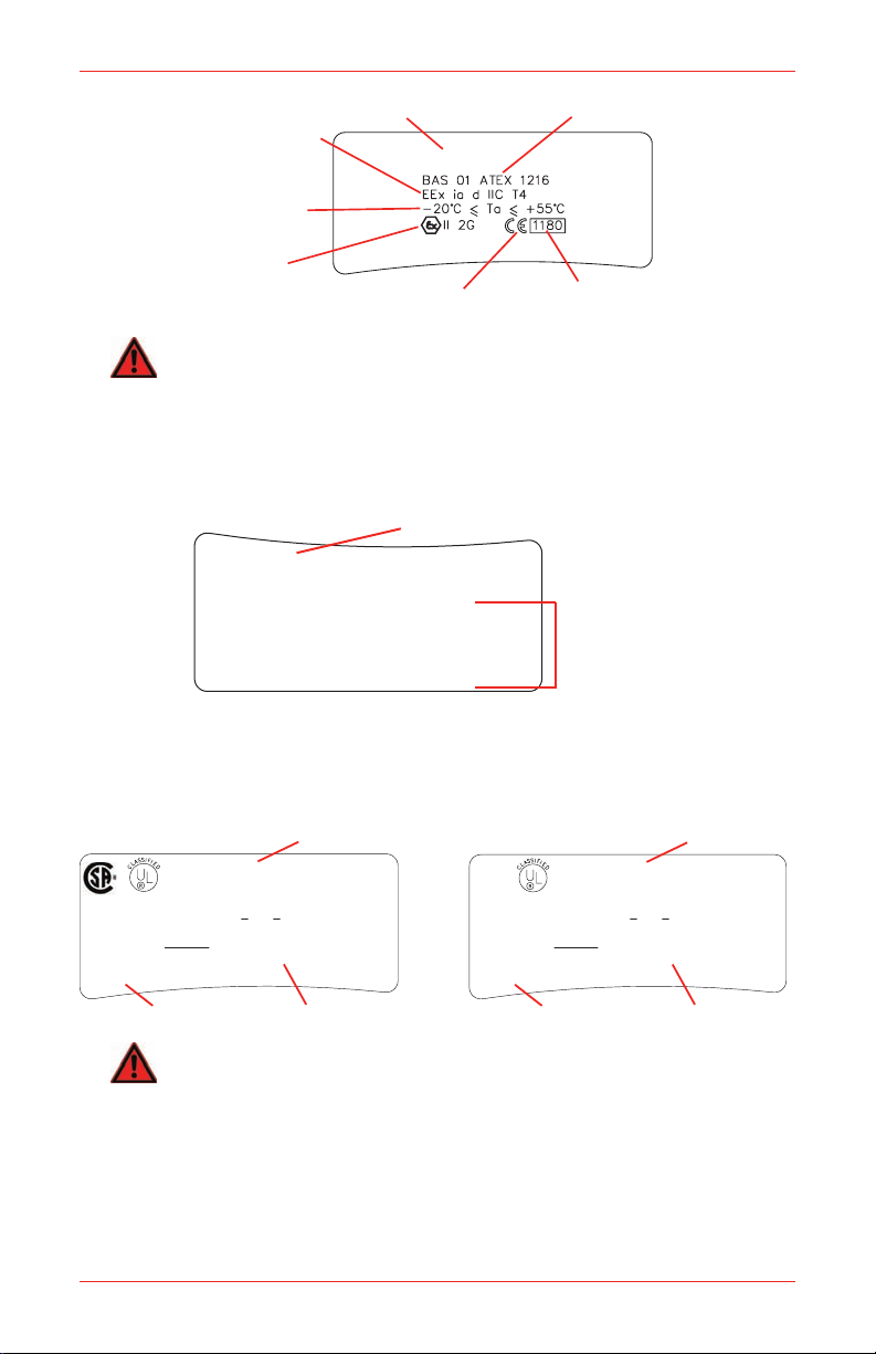
Manufacturers Name and Address
User Cautions
Honeywell Analytics Ltd.
Product Name
Explosion Protection Mark
and Equipment Group
Category
Certified Ambient
Temperature Range
EU Explosive Atmosphere
Symbol and Certification Code
as EN50014:1992
DMT Approval
CE Mark - Conforms
to all EC Directives
Identification No. of AT EX
Notified Body
Brazilian
Approval
Australian Mines
Approval
Australian
Surface Approval
Certification Number
IMPACT GAS DETECTOR
Maritime Equipment Directive
Inmetro Approval
Neotronics Equipment Labels
An explanation of the information on the equipment label is shown below.
Neotronics CENELEC (ATEX) Certification Label
An explanation of the information on the CENELEC (ATEX) certification label is
shown below.
Neotronics Impact Pro non-IR Label:
This instrument has been assessed by EXAM (formerly DMT) for performance
of Oxygen, Methane, Propane, Carbon Monoxide, Hydrogen Sulfide and Carbon
Dioxide (electrochemical cell only) channels.
The label marking indicates this: DMT 02 ATEX G 001
The instrument has been tested in accordance to the following European
Standards.
EN50• 054 & EN50057: 1998 for Combustible Gases (Methane and
Propane).
EN50104: 2002 for the measurement of Oxygen.•
EN45544-1 & EN45544-2: 1999 for the measurement of Carbon Monoxide, •
Hydrogen Sulfide and Carbon Dioxide (electrochemical cell only).
EN50271: 2000 for the assessment of Digital Components and •
Impact / Impact Pro / Impact Pro IR Operating Instructions
Software.
MED: Maritime Equipment Directive•
PFG Nr. 41300502
11
Page 12
Neotronics Impact Pro IR Label:
Product Name
Explosion Protection Mark
and Equipment Group
Category
Certified Ambient
Temperature Range
EU Explosive Atmosphere
Symbol and Certification Code
as EN50014:1992
CE Mark - Conforms
to all EC Directives
Identification No. of AT EX
Notified Body
Certification Number
IMPACT GAS DETECTOR
CAUTION:
Impact Unit Part No. 2302B2000XXX
Sunrise, Florida
33325, USA
Comms Connection onlytoother certified
Impact detectorsin hazardous area
Read and understand instruction manual before
operatingor servicing
Replace/Recharge batteries onlyin Non Hazardous area
Refer to Manual for battery types
Manufacturers Name and Address
User Cautions
Honeywell Analytics Inc.
48X6
only as to intrinsic safety for use in Class I
Groups ABCD hazardous locations
Class I, Groups ABCD Temp Code T4
Tamb -20° C < Ta < + 55° C
Warning - Substitution of components
may impair intrinsic safety
C22.2 No. 152
Exia
UL/CSA Approval
User Warning
Product Name
Impact
Gas Detector
R
48X6
only as to intrinsic safety for use in Class I
Groups ABCD hazardous locations
Class I, Groups ABCD Temp Code T4
Tamb -20° C < Ta < + 55° C
Warning - Substitution of components
may impair intrinsic safety
UL Approval
User Warning
Product Name
Impact
Gas Detector
R
WARNING
Assessment has only been made in the range of 0 to 100%LEL. Use of other ranges
ofammablegasmeasurementonthisinstrumentwillinvalidatethisapproval.
Lumidor Equipment Labels
An explanation of the information on the equipment label is shown below.
Lumidor UL / CSA Certification Label
An explanation of the information on the UL / CSA certification label is shown
below.
Lumidor Impact Pro non-IR Label: Lumidor Impact Pro IR Label:
WARNING
Only the combustible gas detection portion of this instrument has been assessed
by CSA for performance. Furthermore, assessment has only been made in the
0to100%LEL scale(catalyticversion).Useofotherrangesof ammablegas
measurement on this instrument will invalidate approval.
12
Impact / Impact Pro / Impact Pro IR Operating Instructions
Page 13

1� Introduction
The Impact Series is a compact, portable gas monitor designed to be carried or worn
without hindering the user. Its purpose is to monitor the atmosphere continuously
for hazardous levels of up to four gases. Audible and visual alarms alert the user to
danger when hazardous conditions are detected.
The instrument is usually supplied with four gas sensors, for detecting oxygen
(enrichment and deficiency), flammable gases (up to the Lower Explosiv e Limit) and
two toxic gases (for personal safety) all housed in an easily replaceable cartridge.
An alternative arrangement using infrared sensors for flammable or carbon dioxide
is also available.
Various sensor technologies are used to achieve this. In the vast majority of cases,
electrochemical technology is used to detect oxygen and toxic gases while catalytic
combustion technology is used to detect flammable gases. Infrared technology is
used to detect flammable and carbon dioxide gases.
Two types of cartridge are available. One is disposable where the cartridge has
a fixed life and once this has expired the cartridge is disposed of. The other is a
Serviceable Cartridge where the sensors can be individually replaced when required.
The serviceable cartridge type can only be used in the Impact Pro.
Note
Throughout this manual it is assumed that the Impact Series is equipped
with a Disposable Four Sensor Gas Cartridge. References to sensors not
ttedintheusersinstrumentshouldbeignored.
This manual covers all models - some features are not available on all
models. Not all models are available in every country.
The instrument is supplied with dry cell batteries and holders as standard.
Rechargeable batteries and charger can be purchased separately as a kit.
Impact / Impact Pro / Impact Pro IR Operating Instructions
13
Page 14

1�1 Intended Use
The Impact Series has been designed to alert the user to potentially hazardous
atmospheres while carrying out his/her normal duties. Therefore, the instrument
must be kept switched on and worn as close to the breathing area as possible, and
several accessories are provided to allow the instrument to be worn in a number
of different ways:
On the chesta)
On a beltb)
Attached to a body harnessc)
The instrument is provided with various methods to enable the user to comply safely
and easily with confined space regulations.
CAUTION
Hand aspirated remote sampling only provides continuous gas readings as long
as the bulb is being operated.
Honeywell Analytics recommends that the instrument be calibrated at least every
6 months or in accordance with customer site procedures, whichever is sooner.
Correctoperationofthe instrumentshouldbeconrmedwithtestgasofknown
concentration before each use.
If equipped with an electrochemical CO
if CO
is indicated in clean air after the apparatus has been exposed to CO2
2
concentrations above the upper limit of the measuring range. In this case leave
sensor, do not calibrate the CO2 channel
2
the instrument in clean air overnight before calibration.
The calibration interval for the electrochemical CO
month.
sensor shall not exceed 1
2
The use of a Honeywell Analytics Enforcer calibration accessory is strongly
recommended as it enables this to be performed quickly and easily.
WARNING
A sensor which cannot be calibrated or which is found to be out of tolerance should
be replaced immediately. For the disposable cartridge, a replacement cartridge
mustbetted.
14
Impact / Impact Pro / Impact Pro IR Operating Instructions
Page 15
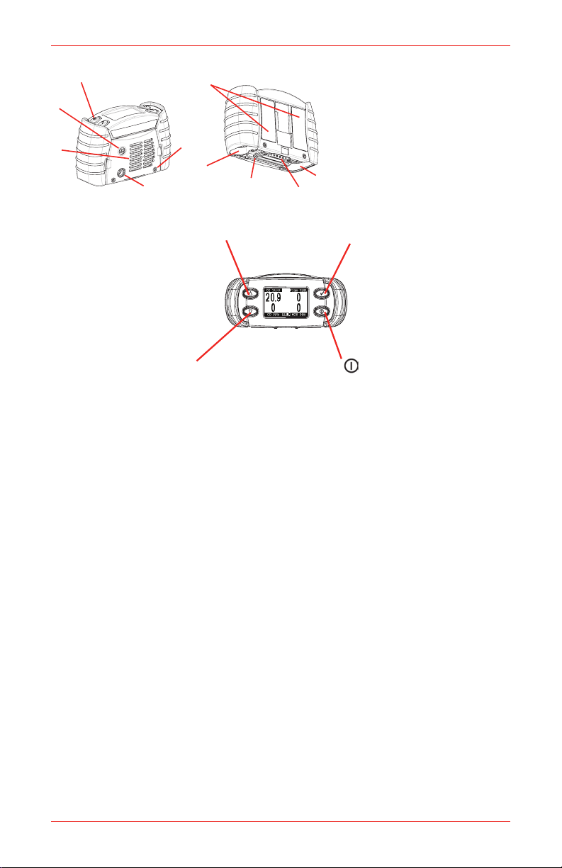
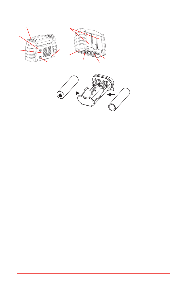
1�2 Product Overview
1
2
3
4
5
6
7
8
9
1. Buttons
2. Pump Aperture
3. Cartridge and Filter Cover Grille
4. Audible Aperture
5. Cover Grille Screws
6. Equipment and Certification Label
7. Battery Compartments
8. T ool
9. Data Connector
7
(yellow) Moves up through
menu screens, and used to
increase values
(green) Used as ‘OK’ in
menus. Accepts alarms,
and resets peak values
(yellow) Moves down
through menu screens and
used to decrease values
(red) On/Off button. Also
used as ‘change’ in menus
On the top of the unit are four buttons (1). Their functions are summarized below:
Pressing any key will automatically activate the display backlight for 10 seconds.
There are currently two types of instrument available - Impact and Impact Pro. The
main differences between the two instruments is that the Impact Pro supports a
range of Serviceable Cartridges (see Section 8.1 Serviceable Cartridges). The
other detail differences are the addition of an internal sample pump, vibrating alarm
and Safelink feature.
The instrument can be further personalized by use of the Impact Configuration Utility
(ICU) PC software, which can be purchased separately as part of the Data Logging
Kit. This allows the user to change various settings and features of the instrument
including, but not limited to Alarm Levels, Autozero function, latching alarms, vibrating
alarm (where fitted), data logging settings and Safelink messages.
Impact / Impact Pro / Impact Pro IR Operating Instructions
15
Page 16
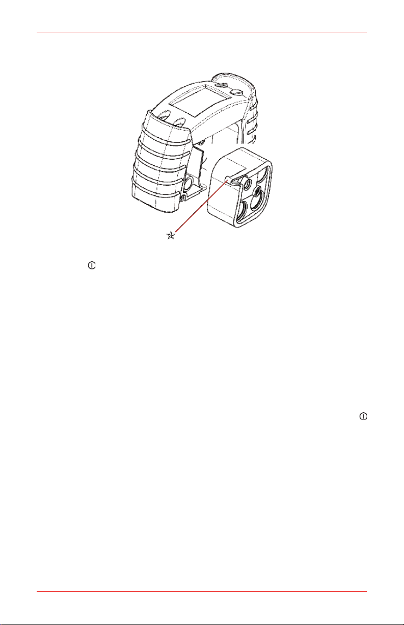
2� Getting Started 2�1 Inserting the Cartridge
If the instrument is switched on then switch it off by pressing and holding 1.
the button. Note: if a cartridge is already fitted, check that the instrument
clock is correct.
Undo the two cover grille screws (5).2.
If a cartridge is already fitted then remove it by undoing the central 3.
screw.
Insert new cartridge into aperture as shown. Ensure that the point ‘4. O’ is
located correctly in the pump or molding (depending on model).
Gently tighten up the central screw to secure in place.5.
Check the condition of the filter on the cover grille (3), and if necessary, 6.
replace it.
If the unit is fitted with a pump replace the pump seal.7.
Replace the front cover, and retighten the two screws (5). 8.
Wait at least 20 minutes. Then switch the Impact on by pressing the 9.
button and check no faults are reported by the instrument. If fault 4 occurs
refit the cartridge.
Once the new cartridge is fitted the instrument will compare it to the 10.
cartridge fitted previously. The instrument will alert the user with warning
if:
the alarm levels are differenta)
the number of sensors is differentb)
the mix of the sensors is different.c)
Press the OK button to accept the new settings from the cartridge, or press 11.
the button to abort the change.
16
If the instrument reports a gas alarm, switch instrument off, wait 20 minutes , 12.
and switch unit on again.
Impact / Impact Pro / Impact Pro IR Operating Instructions
Page 17
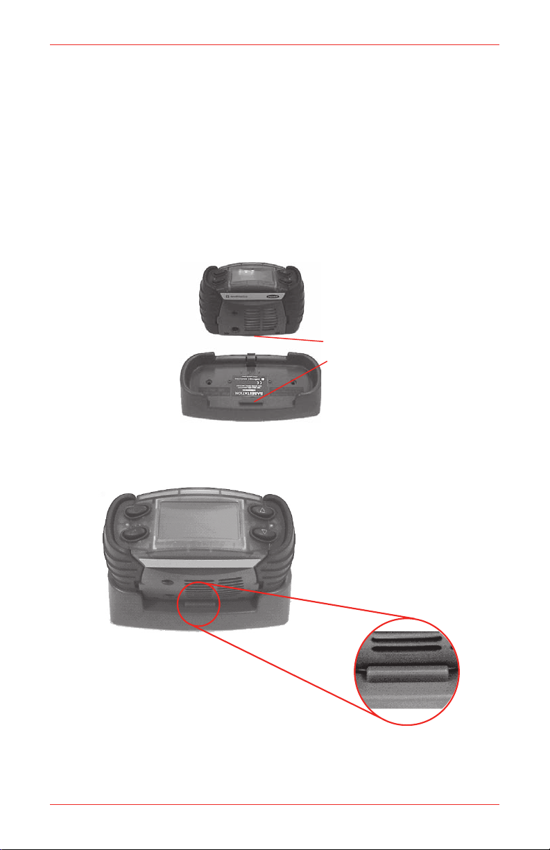
2�2 Charge For First Use
Instrument Lip
Locking Lip
Front
Front
Closeup Detail
Front
Either a rechargeable battery pack or a dry-cell battery source can power the Impact.
For the rechargeable battery it must be charged before first use, to replace any
battery capacity used during transit and storage.
Ensure the Base Station is connected to a suitable power source.1.
Place the instrument in the Base Station.2.
The Base Station employs a locking mechanism to ensure that the Impact is
retained under most operating conditions. To ensure this operates correctly
the following procedure should be followed:
Ensure that the Impact is oriented such that the instrument lip will be a)
inserted under the locking lip.
Insert the front of the Impact at an angle such that the instrument lip b)
slides under the locking lip.
Push down on the rear of the Impact such that the rear locking catch c)
engages.
Impact / Impact Pro / Impact Pro IR Operating Instructions
17
Page 18

Disengaged
Engaged
To remove the Impact press down on the rear locking catch. d)
PSU Connection
Base Station Link Connection
Data Transfer
Connection
All 4 alarm lights will flash indicating the Impact has started
charging.
While charging the instrument, the instrument will flash 2 red LEDs 3.
approximately every 4 seconds. When charging is complete it will light the
green LEDs constantly. A pair of fully discharged battery packs will require
7 hours to recharge fully.
Charging algorithm is based on a timer function so if the charging cycle is
interrupted it will be necessary to leave Impact on Base Station for 7 hours
to produce steady green LED light.
WARNING
Do not charge the battery pack in a hazardous area.
Power and Base Station Link Connection Locations
18
Impact / Impact Pro / Impact Pro IR Operating Instructions
Page 19
2�3 Dry-cell Battery Insertion
1
2
3
4
5
6
7
8
9
1. Buttons
2. Pump Aperture
3. Cartridge and Filter Cover Grille
4. Audible Aperture
5. Cover Grille Screws
6. Equipment and Certification Label
7. Battery Compartments
8. T ool
9. Data Connector
7
-
+
-
+
Undo the two battery compartments (7) using the supplied Allen wrench 1.
(9) provided, on the bottom of each instrument.
Release each dry-cell battery holder and remove the cells if fitted.2.
Insert new cells, ensuring correct orientation by checking that the negative 3.
terminal is at the same end as indicated on the moulding. Ensure they are
of the correct type, to comply with the intrinsic safety requirements.
Replace dry-cell holders in the battery compartments, and retighten 4.
screws.
Instrument is now ready for use.5.
Note
Use the supplied Allen wrench only to remove the battery compartments.
Use of unauthorized tools to attempt to remove the compartments may
lead to damage not covered by the instrument warranty. Replacement
Allen wrenches are available for purchase.
Impact / Impact Pro / Impact Pro IR Operating Instructions
19
Page 20
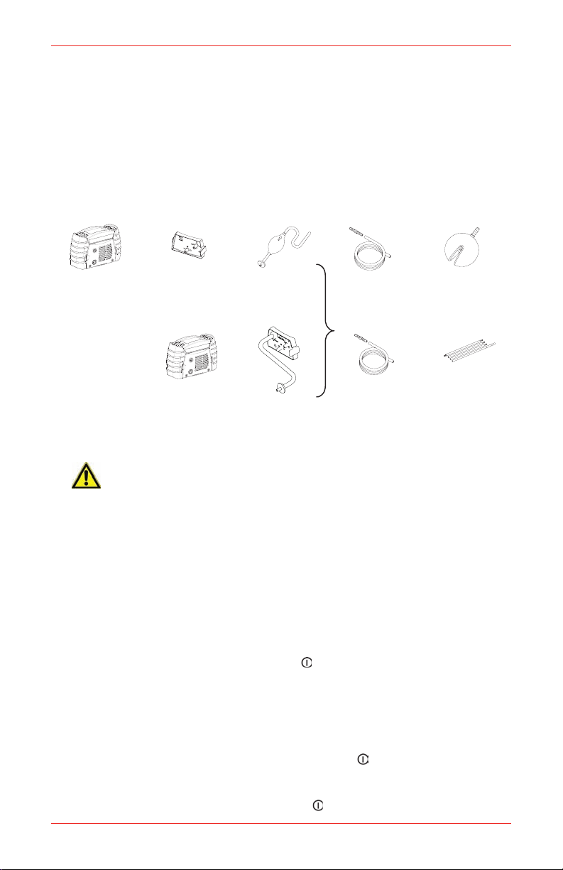
2�4 Sampling
+
+
+
+
+
No Pump
Flow Hood
Hand
Aspirator
Sampling
Tube
Ball Float
With
Pump
Pump
Adapter
Sampling
Tube
1m
Sensing
Probe
In normal operation the Impact is worn on the belt, with its harness, or held by
hand. Once turned on the Impact monitors the atmosphere continuously, which
reaches the sensors by diffusing through the vents of the cover grille or by being
pulled through by the internal pump (if fitted). For non-pump instruments normal
air movements are sufficient to carry the sample to the sensors, and the sensors
react immediately to changes in concentrations of the gases being measured in the
atmosphere immediately surrounding the detector. Depending on your application
and the options fitted to the instrument the environment can be sampled remotely
in a variety of ways, as summarized below:
CAUTION
Hand aspirated remote sampling only provides continuous gas readings while the
bulb is being squeezed. Each time a reading is required, it is necessary to squeeze
the bulb at a rate of one per second until the readings remain stable.
When using the built-in pump or hand aspirator ensure that the sampling tube is
notinsertedintoauid.
2�5 How to turn Impact Series on and off
The Impact has been designed for ease of use, and especially for one-handed
operation - only a single button is needed to turn it on and off.
To turn the instrument on, press the • button until the instrument activates
its audible and visual alarms. It will follow the start-up sequence described
in Section 3. Instrument Start-up.
If the instrument displays an error that no cartridge is fitted then follow the procedure
in Section 2.1 Inserting the Cartridge.
20
To turn the instrument off, press and hold the • button for three seconds,
until it switches off. Note that on some models a password must be entered
to switch the unit off. Failure to enter the correct password will cause the
instrument to continue as though the button had not been pressed.
Impact / Impact Pro / Impact Pro IR Operating Instructions
Page 21

3� Instrument Start-up
Honeywell
Impact Pro
Honeywell
Impact
English
Language
Francais
Italiano
deutsch
Español
Francais
Language
deutsch
Español
Italiano
Nederlands
Flammable Gas
Methane
O2 FLM
CO H2S
Calibration Due
in 120 days
Flammable Gas
CH4
O2 CH4
CO H2S
Calibration Due
in 120 days
Flammable Gas
------
O2 CO2
CO H2S
Calibration Due
in 120 days
Location
Default Location
Operator
DefaultOperator
� -OK
-Change
3�1 Instrument Information
After turning the instrument on it will display the information in the following auto
sequence (depending on model):
The first display identifies the model. While this is shown the alarms are tested and,
if a vibrating alarm is fitted this is also activated.
OR
A Language Selection Screen is then shown (first use
only). Use the s and t buttons to highlight the required
language and press the 3 key to make the selection. Note
that some of the languages may be ‘off screen’ - use the
s and t buttons to access these.
The language can be changed at a later time, if required.
See Section 4.7.6 for details.
The display then shows the gas that the flammable sensor
is set to monitor, the sensors fitted and when calibration is due.
Catalytic Sensor IR Sensor (CH4) IR Sensor (CO2)
The instrument logs data on the operator’s exposure,
if any, to measured gases. It achieves this by
requesting the operator to confirm his/her identity
and the location where the instrument is being used.
The screen displays the last location and operator.
If these are acceptable then press the 3 button. Otherwise select a new location
and/or operator by pressing the button. If the button is not pressed within five
seconds, the instrument will automatically proceed to the next stage in the power-up
sequence.
3�2 Selecting Location / Operator
To change the location and/or operator press the button and the display will show
the current location. Press the s and t buttons to cycle through the list. Once the
correct location has been found then press 3, and follow the same procedure to
select the operator.
Impact / Impact Pro / Impact Pro IR Operating Instructions
21
Page 22

3�3 Fresh Air Auto Zeroing Sensors
Zero sensors?
� -OK
-No
Areyou in
fresh air?
� -Yes, -No
If enabled, the instrument will prompt if you wish to zero
the sensors in fresh air, to adjust for any natural drift that
may have occurred. If the 3 button is pressed the
instrument will then ask the user to ensure that it is being
zeroed in fresh, uncontaminated air. If the button is
not pressed within five seconds, the instrument will
automatically proceed to the next stage in the power-up
sequence.
If the 3 button is pressed the instrument will attempt to
zero the sensors automatically, and display whether the
procedure was successful. The oxygen reading will be
adjusted to 20.9% v/v – the other sensor readings will be
adjusted to 0 ppm and 0% LEL appropriately. If the
button is pressed instead the instrument will use its
current zero values instead and proceed to the monitoring
screen.
Note
This is a ‘soft’ (i.e. temporary) zero which will be discarded when the
instrument is switched off. To permanently adjust the zero, the zero via
the calibration menu must be used (‘hard zero’). See Section 4.9.2.1 for
details.
3�4 Sensor Warm-up Phase
Following display of the Autozero screen it will be noted that the message ‘Cell
Self Test Please Wait’ is displayed. This is displayed while the sensors are in
the warm-up phase of the start-up procedure. If the option of Autozero is declined the
main gas measuring screen will be displayed with the message ‘Warm Up’ being
displayed in place of the gas concentration readings. The instrument should not be
used until the ‘Warm Up’ message has disappeared. The amount of time that the
sensors are in warm up will depend on the sensor type. Table B.3.1 in Appendix B
of this manual gives details of the warm up times for each of the sensors.
3�5 Testing Sensors and Alarms (Calibration and Bump Checks)
To maintain accuracy, the detector should be periodically supplied with a known
concentration target test gas (calibration check) and if the readings differ from
the applied gas concentration by more than 20%, a span calibration should be
performed under conditions of standard temperature (15°C to 25°C/59°F to 77°F),
humidity and pressure. Follow local regulations and your company’s policy on the
frequency of testing.
Note:
If the target gas is not available in a known concentration, or is not
available for testing and a surrogate gas is used, the 20% tolerance
value will not apply. In this case, verify that the instrument responds to
the applied gas and triggers alarms (bump test).
If using the Enforcer for calibration checking or bump testing, refer to Section
4.9.4.
For more information on test gas, contact your local Honeywell Analytics
representative.
22
Impact / Impact Pro / Impact Pro IR Operating Instructions
Page 23
4� Operation
020.9
00
02CO%V/V
ppm
FLM
H2S
%LEL
ppm
�
020.9
00
02CO%V/V
ppm
FLM
H2S
%LEL
ppm
�
�
00
CO ppm
H2S
ppm
00
CO ppm
H2S
ppm
Note
Wherever the manual says ‘select’, the procedure is to use the s and t
buttons to cycle through the list, and then press 3 to select the required
option.
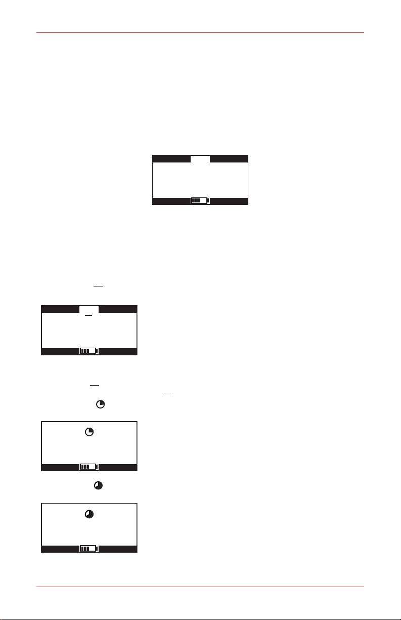
4�1 Monitoring Condition
4�1�1 Display Screens
With no alarm conditions the display will typically show:
The gas sensors and their respective units are displayed, complete with a battery
gauge monitor at the bottom. For an instrument fitted with less than four sensors
each unused sensor position will show ‘---‘.
Several data screens are available and these can be viewed by pressing the s
and t buttons to cycle through. The symbol in the center of the screen will identify
which screen is active.
Peak Screen (
This screen will alternate with a screen showing the minimum value of oxygen. In
this case the
STEL Screen ( )
)
This symbol is displayed when the instrument is displaying
the peak readings for the sensors, i.e. the highest
readings seen since the instrument was switched on or
since they were reset. This is useful for pre-entry checks
for confined space entry. These readings can be reset by
pressing the 3 button while this display is shown.
is replaced by �.
This symbol is displayed when the instrument is displaying
the STEL readings for the toxic sensors. The STEL is a
time weighted average, measured over a 15 minute
reference period. It is used to monitor exposure to toxic
gases in line with current regulations and/or legislation.
LTEL Screen ( )
Impact / Impact Pro / Impact Pro IR Operating Instructions
This symbol is displayed when the instrument is displaying
the LTEL (TWA) readings for the toxic sensors. The LTEL
is a time weighted average, measured over an 8 hour
reference period. It is used to monitor exposure to toxic
gases in line with current regulations and/or legislation.
23
Page 24
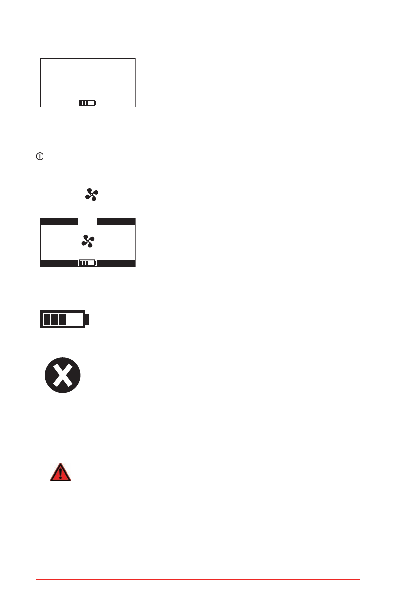
Status Screen
18:33:00
22/Jan/2007
020.9
00
02CO%V/V
ppm
FLM
H2S
%LEL
ppm
This screen shows the current time, date and battery
status.
It is possible to change the instrument date and time
setting as follows: Press the 3 key while this screen is
displayed and the clock setting function will be activated,
with the hour field highlighted. Use the s and t keys
to change the value as required and press the 3 key to move to the minute field.
Again use the s and t keys to change the value and continue until all of the fields
have been correctly set. Finally press the 3 key to store the changes. Note that the
key can be pressed at any time to abort the procedure.
4�1�2 Other Displayed Symbols
If the pump is operating correctly the pump symbol will
rotate.
If the pump flow becomes blocked the instrument will
warn the user and stop the pump to prevent potential
damage. When the user accepts the warning message
the instrument will attempt to restart the pump. There is
no need to remove and refit the Pump Adapter. At this
point, the user should investigate the cause of the
blockage alarm. If the blockage is cleared then the pump will successfully restart.
If the blockage is still present then the instrument will again warn the user that the
pump flow is still blocked. This will repeat until the blockage is removed.
This shows an approximation of the remaining battery capacity within
the instrument. If there is less than 20 minutes remaining battery life
then the instrument will display a ‘Low Battery’ warning.
This will be shown instead of the numerical reading for any sensor
or channel that is faulty, if a zero or span calibration has failed, in
instances of low oxygen and in some cases of high gas concentrations.
Switch the instrument off and then back on. If this does not clear the
fault then recalibrate the sensor or change the cartridge.
This indicates that the sensor output of the indicated channel has
-0
WARNING
If -0.0 v/v% for the electrochemical CO2 sensor channel is permanently displayed,
a sensor zero (during boot procedure) or a zero calibration needs to be performed
in clean air. The alarm level A1 for the CO
24
drifted negative. In severe cases of sensor negative drift, a Warning
51 (Excessive Negative Drift) will be shown. Please see Appendix
A Warning Codes for further details on this warning message.
range must not exceed 0.5 v/v%.
2
Impact / Impact Pro / Impact Pro IR Operating Instructions
Page 25

4�1�3 Confidence Signal
To ensure correct operation the instrument monitors itself and will confirm correct
operation by giving an audible and green visual confidence signal once every 30
seconds. The confidence signal is given when the instrument is able to detect gas
(for example the confidence signal will not be given during pump or sensor calibr ation
phases, or if the sensors are in warm-up).
There is a configurable option to silence the audible confidence signal but the visual
confidence signal will still operate. If the instrument is in a low battery condition the
confidence signal will occur twice every 30 seconds.
Note
The audible confidence signal is the primary indication that the
instrument is functioning correctly. It is therefore strongly recommended
that this feature not be disabled.
4�1�4 Go/No Go Option
A configur able option is available which replaces the numeric values with a 3 symbol
when everything is OK and 8 when there is or has been an alarm or fault, as shown
below. All alarms operate as normal, but other functions and menus are disabled.
This display now also shows the battery capacity as follows.
The Go / No Go Option is configured using the Impact Configuration Utility (ICU)
PC software from the Configuration Screen.
4�2 Atmospheric Alarm Conditions
CAUTION
The Impact portable gas detector has been designed for the detection of oxygen
deciencies and enrichments, ammable andtoxic gas levels. An alarm condition
indicating the presence of one or more of these potentially life-threatening hazards
should be taken seriously.
In the event an alarm is activated when the measured gas concentration exceeds the
pre-set alarm point.
A rapid increase in reading followed by a declining or erratic reading may indicate a
hazardous combustible gas concentration that exceeds the measuring range of the Impact
(i.e. greater than 100%LEL Methane). In the event of the instrument being exposed to a
veryhighlevelofammablegasthefollowingbehaviorwillbenoted.
Warning 54 (low O•
over-range) and an alarm condition will be indicated.
The ammable readingwill be latched to 100%LEL Methane with an alternating•
cross on the channel.
For other sensors reading greater than the measurement range, ‘sss’ alternating with
the full-scale reading will be displayed.
Impact / Impact Pro / Impact Pro IR Operating Instructions
) and an alarm condition will be indicated. Warning 52 (sensor
2
25
Page 26
4�3 Alarm Condition
0
02CO%V/V
ppm
FLM
H2S
%LEL
ppm
1 2
3
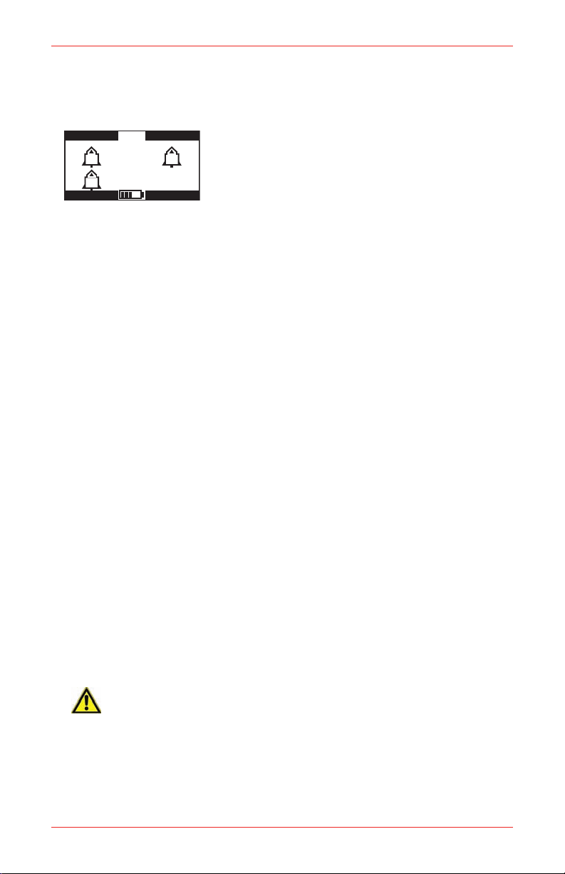
There are two modes of alarm: latching and non-latching. However, the display will
give the same alarm indication:
An alarm symbol will appear in the relevant section of
the display. The alarm symbol contains a number,
indicating the increasing severity of the alarm, with
increasing frequency of the audible and visual alarms.
If there is a STEL/LTEL alarm the relevant icon will
appear and flash.
Any alarm will cause the backlight to be switched on automatically.
4�3�1 Latching Alarms (default)
In the latched condition, once an alarm occurs both audible and visual alarms
continue to operate even after the atmospheric hazard has cleared. Pressing any
of the instrument buttons will clear an alarm. Any subsequent alarm will reactivate
the audible and visual alarms.
4�3�2 Non-latching Alarms
In this mode, should a gas alarm occur the instrument w ould enter an alarm condition.
When the readings return to normal levels the audible and visual alarms will stop.
4�3�3 Vibrating Alarm (where fitted)
If this option is fitted to the instrument, any alarm condition that activates the audible
and visual alarms will also activate the built-in vibrating alarm.
4�3�4 Resetting an Alarm
If an alarm condition occurs it is possible to cancel the alarm by pressing any of the
buttons, once the gas measurements have returned to a safe level. Otherwise, the
instrument will remain in the alarm condition, but the audible alarm will be muted.
Any subsequent alarms that occur 1 second after the previous alarm has been reset
will reactivate the audible alarm.
4�4 Fault and Warning Condition
In addition to the gas alarms, the Impact includes a number of auxiliary alarms
to safeguard proper use of the instrument. At switch-on, the Impact performs an
electronic self-test that assures the user of proper performance. When the Impact
detects that an electronic fault or failure condition has occurred, the audible and
visual alarms are activated and an explanatory message will be displayed.
26
CAUTION
As the Impact is designed to protect from potentially life-threatening atmospheric
conditions, any alarm conditions must be taken seriously.
Impact / Impact Pro / Impact Pro IR Operating Instructions
Page 27

4�4�1 Warning
WARNING
Code-0
See manual
FAULT
Code -0
Pleasecontact
Honeywell Analytics
HAService Number
The instrument displays a warning message for situations
where a fault or error has occurred but may be resolved
by the user.
The ‘Code - 0’ shown here is an example only. A full list
of codes is given in Appendix A.
4�4�2 Fault Condition
If a fault condition is detected during star t-up or
subsequently, the instrument will display a fault message
warning the user and giving a contact number. This will
remain until the instrument is turned off by pressing the
button for at least 3 seconds.
The ‘Code - 0’ shown here is an example only. A full list of codes is given in Appendix
A.
Impact / Impact Pro / Impact Pro IR Operating Instructions
27
Page 28

4�5 Safelink
4�5�1 What is Safelink?
Safelink is a confined space entry communication system between instruments,
fitted with the Safelink feature. It allows one instrument (the ‘attendant’) to display
the gas readings measured by the other connected instrument (the ‘entrant’), up
to a maximum cable length of 100m. Safelink also provides an automatic timed
response system requiring the Entrant’s instrument to return a signal, activated
by the entrant, within a user-specified time interval. Failure of the user to respond
will cause an alarm to be raised on the Attendant’s instrument. Additionally, any
continued pressing on any button on the entrants instrument at any time will cause
an ‘Emergency’ message to appear on the attendant instrument - similar to the action
of a panic button. In Safelink mode the entrant instrument can neither be switched
off, nor can the pump feature (where fitted) be used on either instrument. It will be
found that while the pump is running the Safelink option on the instrument menu
system has been removed. Furthermore, if an attempt to start the pump is made
(on either the attendant or entrant instrument) during Safelink operation an alarm
condition is generated and Safelink Mode has to be exited.
Safelink mode cannot be entered when the batteries are low (i.e. there is less than
1 bar on the battery indication meter).
In some instances a Fault or Warning will not be displayed on the Entrant instrument.
In this case it is important to note that gas alarms on the Entrant instrument are still
indicated on the Entrant and the Attendant instruments.
28
Impact / Impact Pro / Impact Pro IR Operating Instructions
Page 29

4�5�2 Using Safelink
Safelink Mode
Entrant
Attendant
020.9
00
02CO%V/V
ppm
Flm
H2S
%LEL
ppm
Emergency
00:12:34
Select Message
Evacuate Area
Message1
Message2
Are you OK?
Connect the Safelink cable between two instruments. Turn on each instrument and
from the user menu on each instrument select the Safelink mode.
On one instrument select Attendant. When selecting the
Attendant on one instrument the instrument will display
‘locating’ while it attempts to connect with the other
instrument. Once established each instrument will briefly
display ‘Configuring’. The instrument will then show the
readings – ensure that the Safelink symbols appear on
the display. To check the integrity of the communications it is recommended that a
message be sent from the Attendant to the Entrant. Whenever a message must be
responded, the instrument will flash its green LEDs and sound its audible alarm at
a rate of once per second.
Until the Safelink cable is disconnected both instruments will remain in Safelink
mode.
4.5.2.1 Attendant Instrument
The instrument will display the readings being monitored
on the Entrant instrument. The symbol is used to
indicate the Attendant’s instrument. When the symbol is
static it indicates that Safelink communications are
occurring. When it is flashing the Safelink has become
disconnected and the readings will all show ‘---‘, until the
link is restored or the user exits from Safelink mode. All display modes from the
Entrant’s instrument (peak, STEL, etc) are available to the Attendant.
The Select Message menu gives access to two additional actions:
Emergency, which immediately issues a ‘Get Out’ warning to the Entrant.a)
Exit, to enable termination of the Safelink without removing the cable.b)
4.5.2.2 Entrant instrument
The symbol is used to indicate the Entrant’s instrument. When the symbol is
static it indicates that Safelink communications are occurring. When it is flashing
the Safelink has become disconnected.
Only the instantaneous values are shown, although all alarm conditions will operate
as normal.
Impact / Impact Pro / Impact Pro IR Operating Instructions
The status screen shows the duration that Safelink has
been in operation, and the status of the connection as
either Normal, Emergency, or Link failure.
By pressing the 3 button the Attendant has access to a
menu, to select a message to send to the Entrant. These
are configurable using the PC software.
29
Page 30

Select Message
Message2
Message3
Message4
Message 1
By pressing the 3 button the entrant has access to a
Exit Safelink
EXIT
Continue
menu, to select a message to send to the attendant.
These are configurable using the PC software, and could
be used to indicate work progress, e.g. ‘Valve Now
Closed’.
4.5.2.3 Timed Response
At a preselected interval the attendant’s instrument will prompt for the Entrant to be
checked. The Entrant must press any button within a preselected time, otherwise the
Safelink system will assume an emergency situation has occurred and raise alarms
on both instruments. The default interval is 5 minutes. The default time to respond to
a message is 30 seconds. Both of these can be changed using the PC software.
4.5.2.4 Terminating Safelink
To terminate Safelink mode the cable should be
disconnected between the instruments. Both instruments
will display a menu enabling Safelink mode to be switched
off.
Safelink mode must be terminated before attempting to
use the instrument in a Base Station (for charging or calibration) or the Enforcer.
30
Impact / Impact Pro / Impact Pro IR Operating Instructions
Page 31

4�6 Pump (Impact Pro / Impact Pro IR Only)
Pump Test
Please ensure
pump unblocked
Press � to continue
Pump Test
Please wait ...
Pump Test
Please block pump
Press � to continue
Pump Test
OK
Press � to continue
The pump allows gas to be drawn through tubing across the sensors. Fitting the
Pump Adapter will automatically switch the pump on.
If the pump is operating correctly the pump symbol will rotate.
Please refer to Section 4.1.2 Other Displayed Symbols on the operation of the
instrument under blocked flow conditions.
The instrument contains a feature that tests and if necessary dynamically sets the
Pump Stall threshold via a calibration routine. Upon fitting the Pump Adapter, the
user will see the following sequence of screens. The instrument gives instructions
at each stage informing the user as to what operations need to be performed.
Please follow the instructions on screen during the Pump Test and Calibration
procedure. Fit the required length of sample tube of the inlet of the Pump Adapter
together with the Hydrophobic Filter. Fit the Pump Adapter to the front of the
instrument.
Ensure that there is nothing obstructing the flow into the sample pump and press
the 3 button.
The following screen will be displayed briefly.
Followed by…
Use a suitable method to block the end of the sample tube and press the 3
button.
The instrument will now test the pump. Ensure that the blockage is kept in place
for the duration of this test.
If the pump test is successful the following screen will be displayed.
Impact / Impact Pro / Impact Pro IR Operating Instructions
31
Page 32

Remove the blockage from the sample tube and press the 3 button.
Pump Test
Please ensure
pump unblocked
Press � to continue
Pump Calibration
Please wait ...
Pump Calibration
Please block pump
Press � to continue
Pump Calibration
Please wait ...
Pump Calibration
OK
Press � to continue
The internal sample pump feature is now ready for use.
To stop the sample pump, remove the Pump Adapter as described in Section 4.6.1
Removal of the Pump Adapter.
If the Pump Test fails then the pump calibration procedure will start.
Ensure that there is nothing obstructing the flow into the sample pump and press
the 3 button.
The instrument will then perform the first part of the pump calibration.
Use a suitable method to block the end of the sample tube and press the 3 button.
The pump calibration will now commence.
Ensure that the pump is kept in a blocked state until the following screen is
displayed.
Remove the blockage from the sample tube and press the 3 button.
The internal sample pump feature is now ready for use.
If the Pump Calibration fails (please see the diagnostic tab le at the end of this section)
then use of the sample pump is inhibited. The Pump Adapter must be removed from
32
Impact / Impact Pro / Impact Pro IR Operating Instructions
Page 33

the instrument and the fault investigated. To correctly remove the Pump Adapter,
follow the instructions in Section 4.6.1.
Removal of the Pump Adapter will turn the pump off.
Below 0°C the efficiency of the pump will be adversely affected, requiring a longer
sampling time.
The following is a list of possible problems that could cause the instrument to fail
the various tests detailed in this procedure.
Symptom Possible Cause Remedy
The instrument reports
‘Pump Test Fail’
The instrument reports
‘Pump Calibration Fail’
PUMP FAULT and
WARNING 16
‘Pump Fault’ screens are
di spl ayed foll ow ing th e
Pump Calibration.
The sample pump is in an uncalibrated
state or the operating conditions of
the pump have changed signicantly
since the last calibration.
The pump was not blocked correctly
when required.
A blocked condition was not detected
within 30 seconds of the star t of
the test.
The pump was not blocked correctly
when required.
There is a leak in the system. Check that the following items
A blocked condition was not detected
within 30 seconds of the star t of
the test.
The Pump Assembly is faulty. Request a new Pump Assembly
The Pump Calibration has failed. Remove the Pump Adapter and
Perform the Pump Calibration to
recalibrate the pump.
Remove the Pump Adapter and
ret to restart the test. Ensure that
the pump is blocked correctly when
instructed to.
Remove the Pump Adapter and
ret to restart the test. Ensure that
the pump is blocked as soon as
the ‘Please block pump screen’ is
displayed.
Remove the Pump Adapter and
ret to restart the test. Ensure that
the pump is blocked correctly when
instructed to.
are correctly tted and/or are not
damaged.
Pump Seal (behind front cover)•
Sample Tube•
Pump Adapter•
Cover grille•
Remove the Pump Adapter and
ret to restart the test. Ensure that
the pump is blocked as soon as
the ‘Please block pump screen’ is
displayed.
or contact Honeywell Analytics for
assistance.
invest igate th e fau lt (s ee The
instrument reports ‘Pump Calibration
Fail’ above).
Impact / Impact Pro / Impact Pro IR Operating Instructions
33
Page 34

4�6�1 Removal of the Pump Adapter
User Menu
Flammable
Calibration
Operator
Instrument
Safelink
Language
User Menu
Flammable
Calibration
Operator
Instrument
Safelink
Language
Flammable
Methane
Propane
Butane
Pentane
To ease the removal of the Pump Adapter, follow the steps below.
Support the end of the Pump Adapter close to the inlet port using the 1.
thumb of one hand.
Press on the top of the clip using the thumb of the other hand until a click 2.
is heard.
Lift the Pump Adapter clear of the instrument.3.
4�7 Menus
While the gas monitoring screen is displayed, pressing the 3 button will provide
access to menus, depending on the model.
Calibration is not permitted until the sensors have warmed-up and been self tested or
if the pump is running. If you access the user menu under any of these circumstances
the Calibration option will not be available. The Safelink option (where applicable)
will not be available when the internal sample pump is running or when the batteries
are low (i.e. there is less than 1 bar on the battery indication meter).
4�7�1 Flammable Gas Selection
For catalytic sensors, it is possible to set the display to read for specific flammable
gases. Select the required flammable gas. The instrument will automatically adjust
its internal correction factors.
Note that for:
EN50054 100% LEL Methane = 5.0% v/v
EN61779 100% LEL Methane = 4.4% v/v
u
34
Impact / Impact Pro / Impact Pro IR Operating Instructions
Page 35

4.7.1.1 Flammable Cross-Sensitivity Table
Flammable Gas
Hydrogen 125 142
Methane 100 100
Ethylene 91 88
Methanol 83 95
Ethane 90 85
Ethanol 67 71
Propane 68 66
Butane 56 59
Pentane 56 63
Octane 42 47
EN50054
Relative Sensitivity
(% of Methane Reading)
EN61779
Relative Sensitivity
(% of Methane Reading)
Note
The above data are applicable only to instruments that have catalytic
sensorsconguredtodisplaytheFlammablegasin%LEL.
The previous table and the cross-sensitivity feature offered in the Impact and Impact
Pro are supplied for indicative purposes only. The following points should be noted
when using the table or the software feature.
There is variability in sensor cross-sensitivity between methane and other 1.
flammable compounds. Therefore, if the instrument is calibrated to Methane
(including Enforcer calibrations), the reading when other Flammable gases
are selected will be subject to variation.
For more accurate detection of non-Methane gases, the Flammable Channel of 2.
the instrument should be calibrated to Propane, P entane or Butane (selectable
from the Settings option in the Calibration Menu). In this instance the reading
obtained when Methane is selected may be subject to inaccuracy.
Maximum accuracy will be obtained by calibrating with the target gas, and is 3.
therefore the preferred method.
Target Gas Recommended Calibration Method
Enforcer
Methane
Propane
Butane
Pentane
Other
ammable
gases
UI Calibration (using Methane as the selected calibration gas)
PC Calibration (using Methane as the selected calibration gas)
UI Calibration (using Propane as the selected calibration gas)
PC Calibration (using Propane as the selected calibration gas)
UI Calibration (using Butane as the selected calibration gas)
PC Calibration (using Butane as the selected calibration gas)
UI Calibration (using Pentane as the selected calibration gas)
PC Calibration (using Pentane as the selected calibration gas)
UI Calibration (using Propane, Butane or Pentane as the selected calibration gas)
PC Calibration (using Propane or Butane as the selected calibration gas)
Impact / Impact Pro / Impact Pro IR Operating Instructions
35
Page 36

4�7�2 Operator
Software Revision
Version 2.6
Serial Number
0000000000
Calibration Due
in 34 days
02 %V/VFLM %LEL
50
80
120
23.0
19.0
17.0
FlammableGas
Methane
A1
A2
A3
50
100
150
100
50
25
50
100
50
25
A1
A2
A3
STEL
LTEL
CO ppm
H2S
ppm
Pump
Fitted
Data Logging
Gas
Safelink
Fitted
Last Calibration
1 Jan 2001
Autozero
Enabled
GasAlarms
Latched
Battery
Rechargeable
Vibrating Alarm
Enabled
Language
English
Cartridge SN
0001138
Date of Manufacture
25/Jun/2001
Boot ROM Version
Impact Boot 1.4+
Cartridge Type
Standard
Install By
26/Dec/2001
Date of Activation
9/Aug/2001
Honeywell Analytics
Sunrise, FL
800 538 0363
This allows a new operator and/or location to be selected without restarting the
instrument.
4�7�3 Calibration
See Section 4.9 Calibration for full details.
4�7�4 Instrument Details
Several screens are available detailing the instrument set-up, such as alarm levels.
These can be viewed by pressing the s and t buttons to cycle through them. To
access User Menu press 3 while in monitor mode. Scroll down to highlight Instrument
and press 3 again. Some examples are shown below and these are indicative only.
Information shown will vary according to model, country, product application and /
or specific requirements.
This information is also available at switch-on of the
instrument (see Section 3.1 for details).
These are the alarm level settings for oxygen and
flammable sensors. There are no associated STEL or
LTEL alarms for the two gas channels displayed at the
top. h indicates a rising alarm and i indicates a falling
alarm.
The following displays indicate whether particular options are fitted and how the
instrument is currently configured.
The following additional information is also displayed:
36
This shows the alarm levels for the toxic sensors.
Impact / Impact Pro / Impact Pro IR Operating Instructions
Page 37

4�7�5 Safelink
For Impact Pro instruments the additional menu for Safelink is available. It is used
to initiate communication via Safelink to another Impact Pro instrument.
The Safelink option (where applicable) will not be available in the following
situations.
When the internal sample pump is running.•
When the batteries are low (i.e. there is less than 1 bar on the battery •
indication meter).
4�7�6 Language
The Impact is supplied pre-loaded with English, French, German, Italian, Spanish
and Dutch languages, which can be selected using the s, t and 3 keys of the
instrument. In addition one other alternative language can be uploaded to the Impact
(currently available are Portuguese, Danish, Swedish, Norwegian and Finnish) using
the Impact Configuration Utility (ICU) PC software, which is supplied separately.
4�8 Datalogging
There are two types of datalogging. In both cases the information is accessed by
downloading it to a computer using the PC software, which is supplied as part of
the Datalogging Kit. The PC software enables this data to be downloaded, stored,
printed and analyzed. The data can be exported in a format suitable for use with
major spreadsheet software packages. The datalog memory can be automatically
cleared after a successful download – note that this will not change any of the alarm
levels, instrument settings, or calibration gas settings or values of the instrument.
An internal battery will retain the data for 5 years even if the instrument battery is
disconnected or the instrument is switched off. Refer to Section 4.8.1 on how to
install the PC software.
4�8�1 Installing the PC Software
Insert the CD into your CD-ROM drive. 1.
From the Impact Series ICU Utility Page, click “Install Impact Configuration 2.
Utility”.
If the CD does not autorun, click Start, then Run. In the Run dialog box, 3.
type d:\Documents\ICU\setup.exe, where d is the letter assigned to your
CD-ROM drive.
Click OK, then follow the instructions on your screen.4.
Impact / Impact Pro / Impact Pro IR Operating Instructions
37
Page 38

4�8�2 Event Datalogging
All instruments are supplied complete with event datalogging. This records the time
and date whenever an event occurs. When the datalogging memory is full then the
earliest data is overwritten. In event mode the datalogging memory can store at
least 500 events. An event can be:
Instrument switch on•
Instrument switch off•
Peak gas reading while switched on•
Any gas alarm (A3, A2, A1, STEL, LTEL)•
Low battery•
Fault•
4�8�3 Gas Datalogging
Set-up by the PC software for instruments fitted with this full datalogging option,
it enables the instrument to sample at a regular interval (for instance, every 15
seconds).
4�8�4 Output Formats
All the logged data can either be saved to a file with the extension ‘imp’ for use
with the PC Datalogging program or with the extension ‘csv’ for use with most
spreadsheet programs.
Previously, the calibration history, event logging and gas logging was output in a
CSV (Comma Separated Variable format) with the file extension ‘.txt’. Viewing the
information in Microsoft Excel®, required following these steps:
Open the file using Microsoft Excel1.
be set to ‘All files’ to show the files, which have a ‘.txt’ extension.
Excel will recognize the format as ‘delimited text’ and start the ‘Text Import 2.
Wizard’.
For step 1 select ‘Delimited’. Then press ‘Next’.3.
For step 2, in the Delimiters box, ensure Tab and Commas are enabled. 4.
Then press ‘Next’.
For step 3, ensure Column Data Format is ‘General’. Then press ‘Finish’.5.
The data will now be shown in consecutive columns, and can be saved, 6.
printed and analyzed as required.
Also previously, creating a file, which can be opened directly from Windows Explorer
simply by double-clicking on it, required a change to the file extension to ‘.csv’ before
downloading and saving the file.
®
. Note that the ‘Files of Type’ box must
38
Impact / Impact Pro / Impact Pro IR Operating Instructions
Page 39

4�9 Calibration
The accuracy of the Impact instrument should be checked with known concentration
calibration gas before each day’s use. If any sensor fails recalibrate the Impact
before using, or replace the cartridge. It is recommended that the instrument be
calibrated at least every 6 months. The calibration interval for the CO
not exceed 1 month.
The Impact instrument provides three methods of calibration, offering flexibility for
the user. Flow calibration is the traditional method and can be performed, following
instructions displayed on the instrument itself (Section 4.9.2 Flow Calibration
– Instrument), or when the instrument is connected to a PC via a Base Station, on
the PC display (See Section 4.9.3 Flow Calibration – PC). An alternative method
for instruments fitted with a combination of oxygen, flammable, carbon monoxide
and hydrogen sulfide sensors only is to use the Enforcer accessory. For all other
gases the flow calibration method must be used.
CAUTION
Use of non-standard calibration gas and/or calibration components when calibrating
the Impact can lead to dangerously inaccurate readings.
The calibration should be carried out in a well-ventilated area to avoid
contaminants.
Do not calibrate the electrochemical sensor CO
clean air after the apparatus has been exposed to CO
upper limit of the measuring range. In this case leave the instrument in clean air
channel if CO2 is indicated in
2
concentrations above the
2
overnight before calibration.
4�9�1 Contaminants
sensor shall
2
Oxygen sensors may be affected by prolonged exposure to carbon dioxide, and it is
recommended the Impact not be subjected to use in atmospheres containing more
than 25%v/v carbon dioxide (CO2). Oxygen sensors may read high in the presence
of carbon dioxide.
Flammable sensors may be affected by exposure to Silicone substances; organic
phosphorus containing compounds and halogenated organic compounds. Although
the flammable sensors used in Impact and Impact Pro have a high resistance to
Hydrogen Sulfide (H2S) poisoning some loss in sensitivity should be expected.
Therefore it is strongly recommended repeated gassing with H2S or gas alarms
on the H2S channel should be followed by checking and if necessary re-calibration
of the Flammable sensor. The sensors on average will lose approximately 20% of
their sensitivity when subjected to forty applications of H2S for a period of 1 minute
each.
The toxic sensors are designed to be gas specific, minimizing the effects of common
cross-interfering gases. The table below summarizes the effect of various gases on
the Carbon Monoxide and Hydrogen Sulfide sensors.
Impact / Impact Pro / Impact Pro IR Operating Instructions
39
Page 40

Applied Gas
Acetone (1000 ppm) 0 0
Acetylene (40 ppm) 0 80
Ammonia (50 ppm) 0 0
Carbon Monoxide (50 ppm) 0 50
Carbon Dioxide (5000 ppm) 0 0
Chlorine (0.5 ppm) 0 0
Ethanol (2000 ppm) 0 3
Ethylene (100 ppm) 0 85
Hydrogen (100 ppm) 0 20
Hydrogen Sulde (10 ppm) 10 0
Iso-Propanol (200 ppm) 0 0
Nitric Oxide (25 ppm) 0 4
Nitrogen Dioxide (3 ppm) 0 0.5
Sulfur Dioxide (2 ppm) 0 0
H2S Response
(ppm)
CO Response
(ppm)
40
Impact / Impact Pro / Impact Pro IR Operating Instructions
Page 41

4�9�2 Flow Calibration – Instrument
Flow Regulator
Pressure Gauge
Gas Cylinder
On/Off Valve
Gas Tube
Flow Adapter
Password:
XX ..
Calibration
Span
Settings
Zero
Note:
The following equipment is required:
Put the instrument into calibration mode by using the menu. If so configured it will
be necessary to enter a password before access to calibration is possible.
and NH3 sensors, see Section 8 Special Considerations for Cl2
For Cl
2
and Special Considerations for NH
for more information,
3
cylinder of calibration gas (either certified individual gas per sensor or a •
certified multi-gas mixture)
flow adapter: ensure that the tubing is fitted to the port marked ‘IN’ (except •
for Cl
cartridges where the tubing should be fitted to the port marked
2
‘OUT’).
flowmeter/regulator set to 300 ml/min•
tubing•
When performing a flammable span gas concentration the instrument will assume
the use of the gas selected. However, after calibration it will revert to the flammable
gas that the instrument is set to measure. No intervention by the user is required.
For Methane or Propane calibrations the following conversion should be used.
EN50054 100% LEL Methane = 5.0% v/v
EN50054 100% LEL Propane = 2.0% v/v
EN61779 100% LEL Methane = 4.4% v/v
EN61779 100% LEL Propane = 1.7% v/v
If other values are required, adjustment of the calibration point should be carried
out as detailed in Section 4.9.2.2 Span.
Impact / Impact Pro / Impact Pro IR Operating Instructions
The keys must be pressed in the correct sequence,
otherwise the password will be rejected. As each key is
entered the ‘.’ will be replaced by ‘X’.
The calibration procedure requires a zero, followed by a
span. The span requires specific concentration of
calibration gas that matches those held in the settings.
Select the required option.
41
Page 42

4.9.2.1 Zero
Zero
O2
Flm
CO
H2S
All
Press when
in fresh air?
�
Zero
Pleasewait...
Zero
OK
Press to continue�
Zero
Fail
Presstocontinue�
or
Span
FLM
CO
H2S
All
Applygas at
0.3L permin
� -OK, - Abort
If calibrating the electrochemical CO2 channel, refer to the CAUTIONS in Section
4.9.
The display will show the sensors fitted in the cartridge,
and offer the option to ‘hard’ zero an individual channel
or all four simultaneously. O2 is automatically
highlighted.
Assuming “All” is selected by pressing the s and 3 keys,
the display will show:
The zero must be performed in fresh, uncontaminated
air. Alternatively, a supply of compressed air with an
oxygen content of 20.9% v/v can be used.
After pressing the 3 button the instrument will display the
following while zeroing the sensor.
Once the zero is complete the instrument will display whether the zero was
successful.
If the zero was unsuccessful repeat the zero ensuring that the instrument is in fresh
air. If a second failure occurs contact local service center or Honeywell Analytics for
assistance. After a successful zero a span should be performed.
4.9.2.2 Span
The display will show the sensors fitted in the cartridge,
and offer the option to span an individual channel or three
simultaneously using a gas mix.
Having selected the gas the display will change to
show:
42
Impact / Impact Pro / Impact Pro IR Operating Instructions
Page 43

Ensure that the Span Calibration Setting matches that of the gas concentration
Span
Please wait...
Span
OK
Press to continue�
Span
Fail
Presstocontinue�
or
being applied. If not, press the button to change the setting. See Section 4.9.2.3
for instructions.
The following table gives the current set allowable range of Span Gas
Concentrations:
Gas Type Allowable Range
Methane (catalytic sensor) 20% LEL to 100% LEL
Carbon Monoxide 50 ppm to 500 ppm
Hydrogen Sulde 15 ppm to 50 ppm
Carbon Dioxide 0.5% v/v to 2.1% v/v
Chlorine 2 ppm to 10 ppm
Ammonia 10 ppm to 100 ppm
Gas Type Allowable Range
Sulfur Dioxide 5 ppm to 20 ppm
Nitrogen Dioxide 5 ppm to 20 ppm
Methane (%LEL IR) 20% LEL to 100% LEL
Methane (%v/v IR) 40% v/v to 60% v/v
Carbon Dioxide (%v/v IR) 0.5% v/v to 3% v/v
If calibrating the electrochemical CO2 channel, turn on the gas 2 minutes before
pressing the 3 button.
After pressing the 3 button the instrument will display
this message while spanning the sensor.
Once the span is complete the instrument will display whether the span was
successful.
If the span was unsuccessful repeat the span ensuring that the calibration gas used
is of the correct concentration, there is sufficient gas in the cylinder and that the flow
rate is correct. If a second failure occurs contact local service center or Honeywell
Analytics for assistance. If the calibration is successful, the unit will automatically
update the next calibration required by date by the predefined calibration interval
value (default 180 days).
Note:
If the ’Hard Zero’ is omitted then the calibration is retained only for the
current session and the calibration date will not be updated.
4.9.2.3 Calibration Gas Settings
WARNING
Verify that the concentration shown on the calibration gas settings screen is the
same as the concentration printed on the label of the calibration gas cylinder
that will be used. Using the wrong concentration may cause incorrect adjustment
during calibration procedures, and lead to dangerously inaccurate readings during
normal operation.
Impact / Impact Pro / Impact Pro IR Operating Instructions
43
Page 44

User Menu
Flammable
Calibration
Operator
Instrument
Safelink
Language
u
Calibration
Span
Settings
Zero
Settings
Flm:
CO:
H2S:
50
100
40
%LEL
ppm
ppm
CH4
50
%LEL
Select Gas
Propane
Butane
Methane
Pentane
Select Gas
-----
u
Select the channel to change. The highlighted channel
settings can then be altered using the s (increase) and
t (decrease) buttons, holding the buttons down to
change the setting more rapidly. Press 3 to store the
new settings value.
Assuming catalytic flammable is chosen the instrument will request which calibration
gas is being used, irrespective of what the instrument is set to measure.
The calibration gas screen for IR sensors will not display a gas selection as the IR
sensors are limited in the selection of flammable gases - See Special Notes for
IR Sensors on page 65.
Catalytic Sensor IR Sensor
Honeywell Analytics recommends the following calibration gas concentrations:
Gas Type Concentration
Catalytic Flammable (%LEL): 50% LEL Methane
Flammable (%v/v): 2.5% v/v Methane
Carbon Monoxide: 100 ppm
Hydrogen Sulde: 40 ppm
Gas Type Concentration
Carbon Dioxide: 2% v/v
Methane (%LEL IR) 50% LEL Methane
Methane (%v/v IR) 50% v/v Methane
Carbon Dioxide (%v/v IR) 2% v/v
CAUTION
Performingamanualcalibrationusinggasesoutsidethesespeciedvalueswill
result in a calibration failure.
4�9�3 Flow Calibration – PC
In addition to the items required for flow adaptor calibration (Section 4.9.2), the user
will require the Impact Configuration Utility (ICU) PC software, serial cable, Base
Station and Power supply. These items can be purchased as part of the Datalogging
kit (available separately).
Place the Impact into the Base Station and ensure that the power supply and serial
cable are connected. Switch the Impact on, use Impact Configuration Utility (ICU)
software to perform calibration.
The instrument will display the readings while the calibration process is occurring
and the
Information, such as gas cylinder serial numbers, can also be entered for traceability.
Also, calibration reports can be printed.
44
symbol will be displayed in the center of the display.
Impact / Impact Pro / Impact Pro IR Operating Instructions
Page 45

4�9�4 Enforcer Calibration
This is designed for oxygen, flammable (catalytic or IR LEL
sensor), carbon monoxide and hydrogen sulfide, using a
special-to-type gas cylinder. It offers quick, simple and safe
operation by any user, due to the use of a patented low
pressure, low flow rate system.
Note that the Enforcer cylinder contains dangerous
gases.
Performing a Calibration Check with Enforcer
To perform a calibration check of your Impact unit using the Enforcer, power the unit
on and place it into the Enforcer and follow the on-screen instructions (see Section
4.9.4.1 Enforcer On-Screen Instructions). Then re vie w the peak readings as shown
in Section 4.1.1 Peak Screen.
Performing a Bump Test with Enforcer
To perform a bump test of your Impact unit using the Enforcer, power the unit on then
place it into the Enforcer and follow the on-screen instructions (See Section 4.9.4.1
Enforcer On-Screen Instructions). A bump test is a check of basic functionality
(not a calibration check), so the Impact unit need not remain in the Enforcer for
the full ninety seconds; 30 seconds is usually sufficient. Remove the Impact and
check that all the fitted sensor channels are showing alarms, and that the visual
(red flashing lights) and audible alarms are active.
If there is any doubt about the bump test result, carry out a calibration check as
described above, or a full calibration as described below.
Performing full Calibration with Enforcer
Power up the instrument and perform a ‘hard zero’ (using the zero on the calibration
menu - see Section 4.9.2.1 Zero) then follow the steps in Section 4.9.4.1. If
the Enforcer calibration is successful, the unit will automatically update the next
calibration required by date by the predefined calibration interval value (default
180 days).
Note:
If the ’Hard Zero’ is omitted then the calibration is retained only for the
current session and the calibration date will not be updated.
4.9.4.1 Enforcer On-Screen Instructions
If it is not already fitted, screw the Honeywell Analytics cylinder in tightly 1.
(multi-gas mix for Enforcer), check that the pressure gauge shows gas
pressure is present, and pull back the instrument drawer.
Insert the instrument, by tilting at a slight angle, so that the instrument 3.
front cover locks under the cover lip in the Enforcer as indicated.
Then return the instrument to the vertical. The rear locking mechanism 4.
of the Enforcer will retain the instrument. Now close the drawer firmly.
Impact / Impact Pro / Impact Pro IR Operating Instructions
45
Page 46

The instrument will recognize the Enforcer and display an instruction to 5.
Press to continue�
Enforcer Calibration
or
OK
Press to continue�
Enforcer Calibration
Fail
Presstocontinue�
Enforcer Calibration
Rear Locking catch
Button
press the 4 button to continue.
When 3 is pressed, the user should hear the distinctive ‘click’ of the Enforcer gas
delivery solenoid valve.
After about 90 seconds the instrument will display either a pass or fail.6.
If the instrument reports a failure then check that the gas cylinder has 7.
sufficient pressure. Then repeat once more. Note that the instrument
drawer must be opened and then closed to reactivate the Enforcer. If a
subsequent failure should occur please have the instrument serviced
and calibrated, as it may be due to blocked or dirty filters, or the
sensor(s) has failed.
When completed and successful remove the instrument by pressing 8.
downwards on the rear locking catch and lifting the instrument out. The
instrument will activate all its gas alarms as it detects the gas from the
cylinder, thereby also performing a bump test.
The cylinder should be removed after use.
The instrument automatically switches to a flammable gas setting of methane while
in use with the Enforcer. On completion it will revert to the flammable gas that the
instrument is set to measure. No intervention by the user is required.
5� Fault Finding and Procedures
There are two levels of fault within the instrument.
The first level is a warning, from which the user may be able to recover, e.g. a low
battery. The user must press the 3 button to confirm the warning has been seen.
The second level is usually non-recoverable by the user, and in some cases the
only action available is to switch the instrument off.
In both cases a warning/fault code number is given with a brief description of the
fault, and a contact name/telephone number to enable the user to further assistance
if required. Details of the warning and fault codes are given in Appendix A.
46
Impact / Impact Pro / Impact Pro IR Operating Instructions
Page 47

6� Accessories
WARNING
Do not attempt to charge the battery pack in the hazardous area.
The following accessories are available for use with Impact Series.
6�1 Base Station
(Part Number: P2302B0800)
This unit provides a smart charging facility for instruments
powered by rechargeable NiMH batteries. The instrument is
simply inser ted into the base station whereby it is fast
charged. The instrument controls the charging process and
will indicate when it is fully charged, and then change to a
trickle charge mode to keep the battery topped up until the
instrument is required.
The Base Station also provides a facility to connect the instrument to a PC,
for downloading of logged data, viewing or changing instrument configuration
information, or as a means of instrument calibration.
Ensure that the instrument is not inserted backwards into the Base Station. Firstly
locate the lip at the front of the instrument into the corresponding recess, and then
latch the rear catch. To release, pull back the rear catch (see Section 2.3 Charge
for First Use).
If the instrument is switched on while placed in the Base Station the instrument will
not reach full capacity (typically only 85% if switched on for the entire fast charge
period).
The Base Station accepts an input of 12VDC to 32VDC.
Base Stations may be daisy-chain linked. See Section 6.3 Base Station PSU
Link Cable.
6�2 Base Station Plinth
(Part Number: P2302B0804)
The Base Station can also be mounted on a vertical
surface or on a desk by using the optional plinth.
6�3 Base Station PSU Link Cable
(Part Number: 2302D0821)
Allows Base Stations to be linked together, to a maximum of
5, minimizing cabling and power sockets, and forming a
multibank charger.
Daisy-chained linked Base Stations require the use of Power Supply 2302D0787.
(Note: this power supply must not be used with the Offline Trickle Charger).
Impact / Impact Pro / Impact Pro IR Operating Instructions
47
Page 48

6�4 Offline Trickle Charger
(Part Number: 2302B141x)
Permits off-instrument charging of 2 or 4 instrument battery packs in
14 hours. It enab les 24 hour a v ailability of rechargeab le instruments
with purchase of additional battery packs.
Battery packs must be charged in pairs. A power supply is included
in the trickle charger kit. Specify type when ordering:
UK EU US SAA
X = 4 X = 5 X = 6 X = 7
Example: Tric kle Charger f or US application = 2302B1416
The red LED indicates the batteries are receiving charge. Please note that the battery
packs must be charged in pairs, and ma y be left inserted indefinitely until required.
WARNING
The standard Power Supply unit must not be used when connecting multiple Base
Stations. Overheating of the Power Supply and ultimately failure will result.
6�5 Power Supply for Base Station and Trickle Charger
A range of suitable power adapters is available to power the base station or trickle
charger:
Power Supply Part Number
230VAC 50Hz Euro plug format 2302D0816
230VAC 50Hz UK plug format 2302D0818
120VAC 60Hz USA plug format 2302D0819
240VAC 50Hz Australian plug fmt 2302D0820
12V/24VDC vehicle charger lead 2302D0815
CAUTION
These individual Power Supplies will only supply power to one Base Station or
one Trickle Charger.
48
Impact / Impact Pro / Impact Pro IR Operating Instructions
Page 49

6�6 Enforcer
(Part Number: 2302B0831 UL Version including gas cylinder)
(Part Number: 2302B1336 ATEX Version including gas cylinder)
(Part Number: 2302B0650 Enforcer only)
This test and calibration accessory is only for use with
instruments fitted with any combination of oxygen,
flammable (catalytic or IR LEL sensor), carbon
monoxide and hydrogen sulfide sensors. Its operation
is described in Section 4.9.4 Enforcer Calibration.
This is supplied complete with an Enforcer disposable,
multigas cylinder.
For EMC/RFI Enforcer is certified to EN 50270:1999 Type 1.
6�7 Enforcer Gas Cylinder
(Part Number: 2302D0833 UL Version, containing 2.5% v/v Methane)
(Part Number: 2302D0761 ATEX Version, containing 2.2% v/v Methane)
The Enforcer requires a gas cylinder with specific concentration values, and a
specific valve to maintain the required low pressure and flow rate, which enables
the Enforcer to operate quickly and simply.
6�8 Flow Adapter
(Part Number: P2302B0810)
Allows aspirator to be fitted to the instrument. It is also used
when calibrating using the instrument or a PC. It is colored
grey to differentiate it from the pump adapter. See Section
6.12 Pump Adapter Kit.
6�9 Metal Belt Clip
(Part Number: P2302D0826)
Supplied as standard. Enables the instrument to be worn
on a belt. Slides into recess at back of unit.
6�10 Instrument Webbing Clip
(Part Number: P2302B0382)
Allows the instrument to be clipped to harness webbing.
Impact / Impact Pro / Impact Pro IR Operating Instructions
49
Page 50

6�11 Body Harness Kit
(Part Number: P2302B0822)
Simply clips onto the rear of the instrument. Allows the instrument
to be worn on the chest within the breathing zone. Comes with a
waist strap and neck strap.
6�12 Pump Adapter Kit
(Part Number: 2302B0814)
When attached to the front of an instrument fitted with a pump, the
pump will be automatically activated. Subsequent removal of the
adapter will switch the pump off. This maximizes battery life of the
instrument, and prolongs the life of the pump. It is colored black to
differentiate it from the flow adapter. See Section 6.8 Flow
Adapter.
6�13 10m Sample Tube Kit
(Part Number: 2302B0828)
Extends the sampling reach of the instrument, and can be used
with the hand aspirator or Pump Adapter Kit. Supplied with a
coupler it can be extended beyond 10m (30’) by purchasing
additional kits. The maximum recommended length is 20m and
the sample time should be adjusted accordingly.
6�14 Earpiece
(Part Number: 2302B0841)
For noisy environments the earpiece plugs into the
audible aperture, to allow any audible alarms or signals
to be heard. The vibr ating alarm, if fitted, will still operate.
The instrument audible alarm produces a high sound
level. Caution should be exercised when using the
earpiece.
6�15 Base Station PC Link Cable
(Part Number: P2302D0807 RS232 to RS232)
(Part Number: 151-004-555 RS232 to USB)
This is supplied to connect the Base Station to a standard
9-pin D-type RS232 serial port on a PC or laptop,
running the ICU software. An RS232 to USB cable is
available for PCs not fitted with a serial port.
50
Impact / Impact Pro / Impact Pro IR Operating Instructions
Page 51

6�16 Safelink Cable Assembly
This is available in 3 different lengths and allows Safelink
enabled instruments to be connected together for
communications, see Section 4.5 Safelink.
10m (33’) + 2 x Cable Restraints 2302B0735
50m (150’) + 2 x Cable Restraints 2302B0737
100m (300’) + 2 x Cable Restraints 2302B0746
2302B0746 is supplied with a cable reel and an adapter.
6�17 Safelink Cable Restraint Clip
(Part Number: P2302B0713)
Clips the Safelink cable to a belt to provide a strain relief.
6�18 Hand Aspirator Kit
(Part Number: 2302B0813)
Connects to the flow hood to provide manual aspiration.
The bulb should be squeezed at a rate of once per second,
until a stable reading is obtained. As a guideline, the following
sample tube lengths will require:
Length m (ft) Sampling Time (s)
1 (3) 15
5 (15) 20
10 (30) 25
15 (50) 30
30 (100) 40
6�19 Sensing Probe 1m
(Part Number: 2302B0847)
Used with the bulb operated hand aspirator or the internal
pump if fitted, it allows sampling from above normal height
areas or into areas of low accessibility. Ensure that the
sections of the sampling probe are tightened to prevent
dilution of the sample.
6�20 Ball float
(Part Number: 2302B0846)
Clips to the end of the sampling tube being used, and provides the
dual function of preventing liquid entering the instrument and also
breaking the surface tension of any liquid to release trapped gas.
Impact / Impact Pro / Impact Pro IR Operating Instructions
51
Page 52

7� Routine Maintenance
The Impact Series is designed to operate almost maintenance free under most
conditions, except for the need for regular calibration. However, it is recommended
that on a regular basis the instrument is cleaned and the filters changed.
7�1 Cleaning
The instrument may need cleaning if exposed to dirty or hostile conditions. This
can be easily achieved by wiping over with a damp cloth. Do not use bleaching
products or products containing silicon compounds as these can cause damage
to the sensors.
7�2 Filters
The Gore-tex filter fitted under the cover grille is man ufactured from a water repelling
material to protect the sensors from the ingress of water and other contaminants.
The life of this filter is dependent on the amount of dust and viscous liquids in the
atmosphere. If it becomes dirty (discolored) it will act as a barrier and prevent the
diffusion of the atmosphere onto the sensors, and must be replaced. This is easily
achieved by removing the cover grille screws (Section 1.2 Product Overview (5)),
discarding the old filter and fitting a new filter, using the molded detail to locate it.
Note that for instruments fitted with a chlorine sensor a stainless steel filter (part
number P2302D0823) must be used instead of the Gore-tex filter.
7�3 Battery Charging / Replacement
WARNING
Battery Charging and replacement must not be carried out in a hazardous or potentially
dangerous area.
A mixture of dry cell and rechargeable battery packs must not be used - the instrument
safety system prevents operation in such a situation, and the instrument displays a
fault message and activates the audible and visual alarms.
IftheinstrumentisttedwithanelectrochemicalsensorforCO
instructions in Section 8 Charging Procedure for Impact Pro tted with CO2 Variant
Cartridges.
, please refer to the
2
INFORMATION
To maintain peak battery performance, Honeywell Analytics strongly recommend that
every 4 to 6 months the batteries be fully discharged before recharging. To do this,
removetheImpactfromtheBaseStation(iftted)andswitchtheImpacton.Leave
the Impact to run until it switches off. This may take up to 12 hours depending on
the state of charge of the batteries. A Warning 14 (Battery Low) will be generated
towards the end of this procedure, which can be acknowledged or ignored. Once the
Impacthasswitchedoff,titintotheBaseStationandallowtheinstrumenttofully
recharge before next use.
In severe cases (e.g. when the instrument has not been used for some time) it may
be necessary to repeat this 2 or three times to restore peak battery performance.
Should the batteries in the Impact instrument become excessively discharged (e.g.
when unused for some time) there may be occasions when the alarm LEDs and sounder
will operate when attempting to switch the instrument on before recharging. In this
instance please place the instrument into the powered Base Station and switch the
instrument off when Fault 23 is displayed. The Impact will then proceed to charge
as normal.
52
Impact / Impact Pro / Impact Pro IR Operating Instructions
Page 53

7�3�1 Rechargeable Battery Pack
CAUTION
The rechargeable battery packs are sealed units. Do not attempt to remove the
cellsfromthepacksasthiswillinvalidatethesafetycertication.
Battery packs can be recycled by returning to the nearest Honeywell Analytics
Appointed Distributor.
Remove the battery packs if the instrument will not be used for some time.
The Base Station accessory is used to charge rechargeable
battery packs, provided it is powered from an appropriate
power supply source. The instrument is simply placed in
the Base Station, which charges the packs under the
control of the instrument.
briefly light, to indicate charging will occur.
While charging, two of the red LEDs will flash at a slow rate. Once fully charged the
red LEDs will be switched off and the green LEDs will be constantly lit.
If the instrument is switched on when it is placed in the Base Station the charging
progress will be displayed on the instrument.
If a dry-cell instrument is inadvertently placed in the Base Station no damage will
occur due to a built-in safety system.
In the event that the rechargeable battery packs needs to be replaced or the dry-cell
adapters are to be used to power the instrument, the battery screws (see Section 1.2
Product Overview) are unscrewed using the built-in tool (see Section 1.2 Product
Overview) and the sealed units removed. Replacement rechargeable packs are
inserted into the compartments and the screws tightened.
The full fast charge time for a pair of fully discharged battery packs is 7 hours
indicated by two of the red alarm LEDs flashing approximately every 4 seconds. After
this period the instrument will trickle charge the battery packs indefinitely shown by
the green LEDs being constantly illuminated. Charging algorithm is based on a timer
function so if the charging cycle is interrupted it will be necessary to leave Impact
on Base Station for 7 hours to produce steady green LED light
When first placed in the Base Station all four red LEDs will
7�3�2 Dry Cell
If dry cells are to be used the specific adapters must be used
to comply with certification. Ensure the orientation of the
individual cells is correct, and that they are all of the following
types:
Duracell® MN1500 or Energizer® E91.
WARNING
Use of any other dry-cell battery will render the intrinsic safety approval of the
instrument void.
Impact / Impact Pro / Impact Pro IR Operating Instructions
53
Page 54

8� Routine Servicing
1
2
3
4
Apart from the maintenance described in Section 7 Routine Maintenance the
servicing requirements are limited to:
Calibration•
Changing of the cartridge when required or indicated by the instrument•
Replacing sensors in serviceable cartridges (i.e. non-OFCH combinations •
where supported by the instrument)
8�1 Serviceable Cartridges
Instruments that support serviceable cartridges can have the individual sensors
replaced, instead of replacing the whole cartridge.
The procedure is as follows:
Switch the instrument off and remove the cover grille.1.
Unscrew the central cartridge screw and remove the cartridge.2.
On the underneath undo the two screws (1).3.
Lever out the PCB from the locating tabs (2), on the two sides adjacent 4.
to the screws. Retain the sensor retainer (3) if fitted.
Pull out the PCB.5.
For all sensors except the oxygen, replacing the sensor requires the 6.
user to unplug the existing sensor and locate the new sensor in the
same position.
For the oxygen sensor the two screws (4) must be undone. The tabs of 7.
the replacement sensor must be securely screwed to headers. Ensure
each sensor tab is secured to the correct header.
Replace the PCB in the housing, until it clicks into place.8.
Replace the two screws (1), ensuring the retainer is fitted (3) and insert 9.
the cartridge into the instrument.
Check the cover grille filter and if necessary replace it. 10.
Replace the cover grille and wait at least 20 minutes. Then switch the 11.
instrument on.
The instrument must be calibrated before use.12.
54
Impact / Impact Pro / Impact Pro IR Operating Instructions
Page 55

Special Notes for Cl2 Cartridges
It is important that you read all of the notes below before installation or use of your
new cartridge.
Installation of your Cl2 Cartridge
Note
Cartridge Installation or Replacement must never be carried out in a
hazardous area.
If a cartridge was previously fitted to the Impact Pro into which the Cl1.
cartridge is to be installed, remove the Front Cover Grille using the Allen
Key provided in the bottom of the Impact Pro. Unscrew the fixing in the
center of the cartridge and lift the cartridge from the Impact Pro.
Place the Cl2.
home using the Allen Key. Guide the cartridge if necessary using your
cartridge into the Impact Pro and screw the cartridge fully
2
fingers to ensure that it is seated correctly.
Replace the Pump Seal with the one provided with your cartridge.3.
Remove the existing Filter Assembly from the inside of the Front Cover 4.
Grille by peeling it away. Take the Stainless Steel Filter assembly (supplied
in the Cartridge Kit) and remove the protective backing paper. Locate the
Filter assembly onto the locating pegs on the inside of the Front Cover
Grille and lightly press around the edge of the gasket to secure.
Replace the Front Cover Grille and refit the Allen Key into the bottom of 5.
the Impact Pro.
To complete installation of the cartridge allow at least 20 minutes before 6.
operating the Impact Pro.
After this period of time switch the Impact Pro on and accept the New 7.
Configuration when prompted to do so.
2
Impact / Impact Pro / Impact Pro IR Operating Instructions
55
Page 56

Using your Cl2 Cartridge
Please ensure that the following points are noted when the cartridge is in service.
Always use PTFE tubing (maximum length of 500mm) and a flow rate of 1.
500ml/min when calibrating the Cl2 channel.
Apply all gases to the port marked OUTLET (not INLET) on the Flow 2.
Housing.
With regard to the actual sensors fitted, please perform span calibrations 3.
on the sensors of the Impact Pro cartridge in the following order: Cl
H2S, CO, Flammable.
When performing a Span Calibr ation on the Cl4.
calibration span gas through connected tubing for a minimum of 15
flow Cl
2
minutes without the flow adapter fitted to the Impact Pro before attempting
channel,it is good practice to
2
, NH3,
2
a span calibration. Failure to do so may result in a false calibration of the
Cl
channel.
2
Do not apply Span Calibration gas to the Impact Pro for greater than 5 5.
minutes. Again failure to do so may result in a false calibration of the Cl
channel.
This cartridge is not suitable for pumped mode operation.6.
Due to the open nature of the Stainless Steel filter, there is a greater risk 7.
of water damage occurring to the instrument. Every attempt should be
made to keep the instrument dry.
Refer to the CAUTION given in 8. Section 1.1 of this manual for details on
recommended daily checks on your gas detector.
2
Applied Gas
Effect
on CO
Sensor
Effect
on H2S
Sensor
Effect
on CO2
Sensor**
Effect
on Cl2
Sensor
Effect
on NH3
Sensor
CO (100 ppm) 100 ppm 0 ppm 0% v/v 0 ppm 35 ppm 1 ppm
S (40 ppm) 0 ppm 40 ppm 0% v/v -25 ppm150 ppm 1 ppm
H
2
(0.5% v/v) 0 ppm 0 ppm 0.5% v/v 0 ppm 0 ppm TBA
CO
2
(5 ppm) 0 ppm 0 ppm 0% v/v 5 ppm 0 ppm -2 ppm
Cl
2
NH3 (50 ppm) 0 ppm 0 ppm 0% v/v -2 ppm
Hydrogen
(1000 ppm)
(10 ppm) 0 ppm 0 ppm 0% v/v 2 ppm 0 ppm 10 ppm
SO
2
1
Reading displayed as -0ppm.
** Electrochemical CO2 cell only
56
200 ppm 0 ppm 0% v/v TBA 35 ppm TBA
Impact / Impact Pro / Impact Pro IR Operating Instructions
1
50 ppm TBA
Effect
on SO2
Sensor
1
Page 57

Special Notes for NH3 Cartridges
It is important that you read all of the notes below before installation or use of your
new cartridge.
Installation of your NH
To install the cartridge, follow the instructions below.
Note
Cartridge Installation or Replacement must never be carried out in a
hazardous area.
Cartridge
3
If a cartridge was pr1. eviously fitted to the Impact Pro into which the NH
cartridge is to be installed, remove the Front Cover Grille using the Allen
Key provided in the bottom of the Impact Pro. Unscrew the screw in the
center of the cartridge and lift the cartridge from the Impact Pro.
Place the NH2.
home using the Allen Key. Guide the cartridge if necessary using your
cartridge into the Impact Pro and screw the cartridge fully
3
fingers to ensure that it is seated correctly.
Replace the Pump Seal with the one provided with your cartridge and 3.
replace the Front Cover. Refit the Allen Key into the bottom of the Impact
Pro.
Allow 20 minutes for the sensors to stabilize before first use.4.
To complete installation of the cartridge, switch the Impact Pro on and 5.
accept the New Configuration when prompted to do so.
Using your NH
Cartridge
3
Please ensure that the following points are noted when the cartridge is in service.
The Ammonia channel has1. an extended warm-up time. Although the
other channels of the cartridge will be reading correctly, the detector
should not be used to measure Ammonia until the ‘warm up’ message
has disappeared.
The operating temperature range of the cartridge defaults to that of the 2.
lowest sensor fitted. For NH
this is -20°C to +40°C.
3
Always use PTFE tubing (maximum length of 500mm) when calibrating 3.
the NH
When performing a Span Calibration on the NH4.
practice to flow NH
minimum of 15 minutes without the flow adapter fitted to the Impact Pro
channel.
3
channel it is good
calibration span gas through connected tubing for a
3
3
before attempting a span calibration. Failure to do so may result in a false
calibration of the NH
channel.
3
The accuracy of the instrument must be checked with known concentration 5.
calibration gas before each day’s use. If any sensor fails, recalibrate the
Impact Pro before using or alternatively replace the cartridge. Please refer
to Section 4.9 on general instructions on how to calibrate.
Apply calibration span gas at a rate of 300 ml/min for a period of 5 minutes 6.
before starting the span calibration on the sensor.
With regard to the actual sensors fitted, please perform span calibrations 7.
on the sensors of the Impact Pro cartridge in the following order: Cl
H
S, CO, Flammable.
2
Purge the system with air for a period of 15 minutes between Cl8.
calibrations to avoid interaction between these two gases.
Impact / Impact Pro / Impact Pro IR Operating Instructions
, NH3,
2
and NH3
2
57
3
Page 58

The sensors fitted to Impact Pro may give responses to gases other then 9.
the target gas. The table below gives typical sensor responses to various
gases and should be used as a guide only. Note: Always use the target
gas to perform sensor calibrations.
Your attention is drawn to the cross-sensitivity of the NH10.
presence of H
the NH3 sensor.
S. This is normal operation and is due to the chemistry of
2
sensor in the
3
Applied
Gas
CO
(100 ppm)
S
H
2
Effect
on CO
Sensor
100 ppm 0 ppm 0% v/v 0 ppm 35 ppm 1 ppm
0 ppm 40 ppm 0% v/v -25 ppm150 ppm 1 ppm
Effect
on H2S
Sensor
Effect
on CO2
Sensor**
Effect
on Cl2
Sensor
Effect
on NH
Sensor
(40 ppm)
CO
2
(0.5% v/v)
(5 ppm) 0 ppm 0 ppm 0% v/v 5 ppm 0 ppm -2 ppm
Cl
2
NH
3
(50 ppm)
Hydrogen
(1000 ppm)
SO
2
(10 ppm)
1
Reading displayed as -0ppm.
** Electrochemical CO2 cell only
0 ppm 0 ppm 0.5% v/v 0 ppm 0 ppm TBA
0 ppm 0 ppm 0% v/v -2 ppm
1
50 ppm TBA
200 ppm 0 ppm 0% v/v TBA 35 ppm TBA
0 ppm 0 ppm 0% v/v 2 ppm 0 ppm 10 ppm
Effect
on SO
3
Sensor
2
1
58
Impact / Impact Pro / Impact Pro IR Operating Instructions
Page 59

Special Notes for SO2 Cartridges
It is important that you read all of the notes below before installation or use of your
new cartridge.
Installation of your SO2 Cartridge
Note
Cartridge Installation or Replacement must never be carried out in a
hazardous area.
If a cartri1. dge was previously fitted to the Impact Pro into which the SO
cartridge is to be installed, remove the Front Cover Grille using the Allen
Key provided in the bottom of the Impact Pro. Unscrew the screw in the
center of the cartridge and lift the cartridge from the Impact Pro.
Place the SO2.
home using the Allen Key. Guide the cartridge if necessary using your
fingers to ensure that it is seated correctly.
Replace the Pump Seal with the one provided with your cartridge and 3.
replace the Front Cover. Refit the Allen Key into the bottom of the Impact
Pro.
Allow 20 minutes for the sensors to stabilize before first use.4.
To complete installation of the cartridge, switch the Impact Pro on and 5.
accept the New Configuration when prompted to do so.
Using your SO
Please ensure that the following points are noted when the cartridge is 1.
in service.
The operating temperature range of the cartridge defaults to that of the 2.
lowest sensor fitted.
Always use PTFE tubing (maximum length of 500mm) when calibrating 3.
the SO
When performing a Span Calibration on the SO4.
practice to flow SO2 calibration span gas through connected tubing for a
minimum of 15 minutes without the flow adapter fitted to the Impact Pro
before attempting a span calibration. Failure to do so may result in a false
calibration of the SO2 channel.
The accuracy of the instrument must be checked with known concentration 5.
calibration gas before each day’s use. If any sensor fails, recalibrate the
Impact Pro before using or alternatively replace the cartridge. Please refer
to Section 4.9 on general instructions on how to calibrate.
Apply calibration span gas at a rate of 300 ml/min for a period of 1 minute 6.
before starting the span calibration on the sensor.
With regard to the actual sensors fitted, please perform span calibrations 7.
on the sensors of the Impact Pro cartridge in the following order: Cl
H2S, SO2, CO, Flammable.
If the cartridge contains either NH8.
air for a period of 15 minutes between NH
avoid interaction between these gases.
cartridge into the Impact Pro and screw the cartridge fully
2
Cartridge
2
channel.
2
channel it is good
2
or H2S sensors purge the system with
3
or H2S and SO2 calibrations to
3
, NH3,
2
2
Impact / Impact Pro / Impact Pro IR Operating Instructions
59
Page 60

The sensors fitted to Impact Pro may give responses to gases other then 9.
the target gas. The table below gives typical sensor responses to various
gases and should be used as a guide only. Note: Always use the target
gas to perform sensor calibrations.
Effect
Applied
Gas
CO
(100 ppm)
S
H
2
(40 ppm)
CO
2
(0.5% v/v)
(5 ppm) 0 ppm 0 ppm 0% v/v 5 ppm 0 ppm -2 ppm
Cl
2
NH
3
(50 ppm)
Hydrogen
(1000 ppm)
SO
2
(10 ppm)
1
Reading displayed as -0ppm.
** Electrochemical CO2 cell only
on CO
Sensor
100 ppm 0 ppm 0% v/v 0 ppm 35 ppm 1 ppm
0 ppm 40 ppm 0% v/v -25 ppm150 ppm 1 ppm
0 ppm 0 ppm 0.5% v/v 0 ppm 0 ppm TBA
0 ppm 0 ppm 0% v/v -2 ppm
200 ppm 0 ppm 0% v/v TBA 35 ppm TBA
0 ppm 0 ppm 0% v/v 2 ppm 0 ppm 10 ppm
Effect
on H
Sensor
Effect
S
on CO2
2
Sensor**
Effect
on Cl2
Sensor
Effect
on NH3
Sensor
1
50 ppm TBA
Effect
on SO2
Sensor
1
60
Impact / Impact Pro / Impact Pro IR Operating Instructions
Page 61

Special Notes for Electrochemical CO2 Cartridges
1
9
3
6
ON
20 min
It is important that you read all of the notes below before installation or use of your
new cartridge.
Installation of your electrochemical CO
The cartridge is supplied on a Bias PCB to ensure that the sensor is ready to use
when installed.
To install the cartridge, follow the instructions below.
Note
Cartridge Installation or Replacement must never be carried out in a
hazardous area.
Cartridge
2
If a cartridge was previously fitted to the Impact Pro into which the CO1.
cartridge is to be installed, remove the Front Cover grille using the Allen
Key provided in the bottom of the Impact Pro. Unscrew the screw in the
center of the cartridge and lift the cartridge from the Impact Pro.
Again using the Allen Key provided in the base of the Impact Pro instrument, 2.
unscrew the screw in the center of the new CO
to remove the screw from the bottom of the Bias PCB. Remove the Bias
cartridge. Do not attempt
2
PCB from the Cartridge.
Place the CO3.
home using the Allen Key. Guide the cartridge if necessary using your
cartridge into the Impact Pro and screw the cartridge fully
2
fingers to ensure that it is seated correctly.
Replace the Pump Seal with the one provided with your cartridge and 4.
replace the Front Cover. Refit the Allen Key into the bottom of the Impact
Pro.
To complete installation of the cartridge, switch the Impact Pro on and 5.
accept the New Configuration when prompted to do so. Note: This must
be done immediately after installation in order to maintain correct bias on
the CO
sensor.
2
Allow 20 minutes for the sensors to stabilize before use. Note that the 6.
Impact Pro may be in alarm condition during this time.
2
Using your Electrochemical CO2 Cartridge
Please ensure that the following points are noted when the cartridge is in service.
Always keep the instrument batteries charged or keep fresh alkaline cells 1.
fitted when the cartridge is installed. Never allow the batteries to become
drained.
The operating temperature range of this cartridge is 0°C to +40°C. Do not 2.
use the cartridge outside this range. The cartridge may be stored safely
at temperatures down to -10°C.
Impact / Impact Pro / Impact Pro IR Operating Instructions
61
Page 62

The CO3.
± 10%. Over this pressure range, the reading is directly proportional to
sensor is suitable for use in barometric pressures of 1013mBar
2
barometric pressure.
The calibr ation interval for the CO4.
to the characteristics of the CO2 sensor a significant increase of reading
sensor shall not exceed 1 month. Owing
2
can be expected at temperatures below +10°C, and a significant decrease
at temperatures above +30 °C. To ensure safe operation, always calibrate
the instrument between +10 °C and +30 °C.
The accuracy of the instrument must be checked with known concentration 5.
calibration gas before each day’s use. If any sensor fails, recalibrate the
Impact Pro before using or replace the cartridge.
The sensors fitted to Impact Pro may give responses to gases other then 6.
the target gas. The table below gives typical sensor responses to various
gases and should be used as a guide only. Note: Always use the target
gas to perform sensor calibrations.
Applied Gas
Effect on
CO Sensor
Effect
on H2S
Sensor
Effect
on CO2
Sensor**
Effect on
Cl2 Sensor
Effect
on NH3
Sensor
CO (100 ppm) 100 ppm 0 ppm 0% v/v 0 ppm 35 ppm 1 ppm
H
S (40 ppm) 0 ppm 40 ppm 0% v/v -25 ppm150 ppm 1 ppm
2
CO
(0.5% v/v) 0 ppm 0 ppm 0.5% v/v 0 ppm 0 ppm TBA
2
Cl
(5 ppm) 0 ppm 0 ppm 0% v/v 5 ppm 0 ppm -2 ppm
2
NH3 (50 ppm) 0 ppm 0 ppm 0% v/v -2 ppm
Hydrogen
(1000 ppm)
SO
(10 ppm) 0 ppm 0 ppm 0% v/v 2 ppm 0 ppm 10 ppm
2
1
Reading displayed as -0ppm.
** Electrochemical CO2 cell only
200 ppm 0 ppm 0% v/v TBA 35 ppm TBA
1
50 ppm TBA
Effect
on SO2
Sensor
1
Charging Procedure for Impact Pro fitted with CO2 Variant Cartridges
If using Rechargeable Ni-MH Battery Packs, charging should always be carried out
with the batteries removed from the instrument. This can be achieved by using the
Honeywell Analytics Off-Line Charger. Part numbers of the chargers are given in
Section 6 Accessories.
Remove the exhausted batteries using the special tool found in the base 1.
of the instrument.
Immediately place the instrument, with the batteries removed, onto the 2.
Base Station, which is connected to a Power Supply Unit (PSU). This will
ensure that the CO
not present. Alternatively, fit fully charged batteries.
sensor is correctly biased while the Battery Packs are
2
Place the exhausted batteries into the Off-Line Charger, ensuring that they 3.
are charged in pairs (one each side of the red ‘Charge’ LED). The Off-Line
Charger can accept two pairs (4 total) of Rechargeable Battery Packs. The
red ‘Charge’ LED will illuminate while the batteries as present.
After charging is complete (12 hours minimum), remove the Battery Packs 4.
62
Impact / Impact Pro / Impact Pro IR Operating Instructions
Page 63

from the Off-Line Charger. Remove the instrument from the Base Station
and insert the Battery Packs. Tighten the retaining screw using the special
tool.
The instrument is now ready for use. 5.
Note:
The instrument does not have to be switched on during this procedure,
however if it is switched on a Warning 105 (see Appendix A) will be
shown. This should be accepted. In addition Fault 23 may be reported
when the instrument is removed from the Base Station. If this occurs,
the instrument should be switched off and back on again to reset the
instrument.
Using Alkaline Dry Cells
®
If using Alkaline Cells (Duracell
MN1500 or Energizer® E91) and they require
replacing, ensure that the batteries are not left out of the instrument for more than
15 minutes. This is to ensure correct biasing of the electrochemical CO2 sensor.
WARNING
The following points should be noted.
The Bias PCB supplied with your electrochemical CO1.
rechargeable lithium battery. Do not attempt to recharge the battery under
any circumstances.
Do not reuse the Bias PCB.2.
DonotdestroytheBiasPCBinre.3.
Dispose of the Bias PCB and cartridge packaging in accordance with Local 4.
Regulations.
sensor contains a non-
2
Impact / Impact Pro / Impact Pro IR Operating Instructions
63
Page 64

Special Notes for NO2 Cartridges
It is important that you read all of the notes below before installation or use of your
new cartridge.
Installation of your NO2 Cartridge
Note
Using your NO
Please ensure that the following points are noted when the cartridge is in service.
Cartridge Installation or Replacement must never be carried out in a
hazardous area.
If a cartridge was previously fitted to the Impact Pro into which the NO1.
cartridge is to be installed, remove the Front Cover Grille using the Allen
Key provided in the bottom of the Impact Pro. Unscrew the screw in the
center of the cartridge and lift the cartridge from the Impact Pro.
Place the NO2.
home using the Allen Key. Guide the cartridge if necessary using your
cartridge into the Impact Pro and screw the cartridge fully
2
fingers to ensure that it is seated correctly.
Replace the Pump Seal with the one provided with your cartridge and 3.
replace the Front Cover. Refit the Allen Key into the bottom of the Impact
Pro.
Allow 20 minutes for the sensors to stabilize before first use.4.
To complete installation of the cartridge, switch the Impact Pro on and 5.
accept the New Configuration when prompted to do so.
Cartridge
2
The operating 1. temperature range of the cartridge defaults to that of the
lowest sensor fitted. The temperature range of the NO
to +50°C.
Sensor is -20°C
2
Always use PTFE tubing (maximum length of 500mm) when calibrating 2.
the NO
channel.
2
When sampling remotely (i.e. using the internal sample pump or hand 3.
aspirator together with tubing) users should be aware of increased sample
times. For NO
for every 10m of tubing used.
When performing a Span Calibration on the NO4.
practice to flow NO
minimum of 15 minutes without the flow adapter fitted to the Impact Pro
the sample time will increase by approximately 90 seconds
2
channel it is good
calibration span gas through connected tubing for a
2
2
before attempting a span calibration. Failure to do so may result in a false
calibration of the NO
channel.
2
The accuracy of the instrument must be checked with known concentration 5.
calibration gas before each day’s use. If any sensor fails, recalibrate the
Impact Pro before using or alternatively replace the cartridge. Please refer
to Section 4.9 on general instructions on how to calibrate.
Apply calibration span gas at a rate of 300 ml/min for a period of 1 minute 6.
before starting the span calibration on the sensor.
With regard to the actual sensors fitted, please perform span calibrations 7.
on the sensors of the Impact Pro cartridge in the following order: Cl
H2S, NO2, SO2, CO, Flammable.
If the cartridge contains NH8.
, H2S or Cl2 sensors purge the system with air
3
, NH3,
2
2
64
Impact / Impact Pro / Impact Pro IR Operating Instructions
Page 65

for a period of 15 minutes between NH3, H2S or Cl2 and NO2 calibrations
to avoid interaction between these gases.
The sensors fitted to Impact Pro may give responses to gases other then 9.
the target gas. The table below gives typical sensor responses to various
gases and should be used as a guide only. Note: Always use the target
gas to perform sensor calibrations.
Applied
Gas
CO
(100 ppm)
S
H
2
(40 ppm)
CO
2
(0.5% v/v)
Cl
2
(5 ppm)
NH
3
(50 ppm)
Hydrogen
(1000 ppm)
SO
2
(10 ppm)
NO
2
(10 ppm)
1
Reading displayed as -0ppm.
** Electrochemical CO2 cell only
Effect
on CO
Sensor
100 ppm 0 ppm 0% v/v 0 ppm 35 ppm 1 ppm 0 ppm
0 ppm 40 ppm 0% v/v -25 ppm150 ppm 1 ppm -3.2 ppm
0 ppm 0 ppm 0.5% v/v 0 ppm 0 ppm TBA TBA
0 ppm 0 ppm 0% v/v 5 ppm 0 ppm -2 ppm
0 ppm 0 ppm 0% v/v -2 ppm
200 ppm 0 ppm 0% v/v TBA 35 ppm TBA TBA
0 ppm 0 ppm 0% v/v 2 ppm 0 ppm 10 ppm 0 ppm
0 ppm 0 ppm 0% v/v 0 ppm -5 ppm1-10 ppm110 ppm
Effect
on H2S
Sensor
Effect
on CO2
Sensor**
Effect
on Cl2
Sensor
Effect
on NH3
Sensor
1
50 ppm TBA TBA
Effect
on SO2
Sensor
Effect
on NO2
Sensor
1
1
5 ppm
Impact / Impact Pro / Impact Pro IR Operating Instructions
65
Page 66

Special Notes for IR Sensors
The Impact Pro IR offers many benefits that enable the user to achieve drift-free
operation and longer-term stability, when compared with catalytic bead (pellistor)
or photo ionization detectors (PID). IR sensors are immune to poisons such as
silicones that can contaminate Catalytic sensor types. IR sensors can detect
hydrocarbon gas levels in the absence of oxygen (O
with catalytic bead sensors. Typical applications would be to measure hydrocarbon
gases under nitrogen storage blankets or other inert atmospheres. IR sensors
generally enable users to achieve their application requirements with an overall
lower cost of ownership
There are three (3) types of infrared sensor that can be fitted; two for flammable
gas (%LEL and %Vol options), and the third for Carbon Dioxide (CO
IR sensor can be installed per cartridge. Both IR flammable sensors are calibrated
for methane, although they will be sensitive to many hydrocarbon gases. Please
note the following:
Hydrogen (H
) cannot be detected using the IR principle.
2
By default, no alarms are provided for the 0-100%/Volume IR sensor. The user can
setup alarm levels via the ICU software.
WARNING
All IR sensor cartridges require a modied Impact Pro IR cartridge bay,which
isdesignatedasmodicationstate15.Ifnotpresent,thismodicationmustbe
performed by your authorized Honeywell Analytics Service Center. Failure to do
this may lead to physical damage when attempting to insert the new IR sensor
cartridge and will not be covered by warranty.
), which cannot be achieved
2
). Only one
2
CAUTION
Infraredsensorsforammablegasescannotdetecthydrogen(H2). If the environment
is suspected of containing combustible levels of hydrogen, a cartridge that uses a
standard catalytic bead sensor should be used with the Impact Pro instead.
CAUTION
Any electrochemical sensors in this cartridge cannot operate accurately in oxygen
decientenvironmentsandshouldnotbeusedforcontinuousmonitoringininert
atmospheres.
Compatibility
The settings for the new IR sensor are stored in the smart cartridge. Those i)
cartridges that house the new IR sensors have a slightly modified internal
arrangement. Existing Impact Pro models will need to be returned to an
approved service center to make sure the firmware is current and to get
updated certification and notification labels applied. In addition, earlier models
of Impact Pro will have to have modification of the cartridge-mounting boss.
New Impact Pro IR units ordered will be configured with the appropriate
labelling prior to shipment (see part numbers below). Contact your approved
Honeywell Analytics Service Center for full details of this modification.
2302B20009UE - Impact Pro IR version, certified UL/CSA only
2302B10009BER - Impact Pro IR version, certified ATEX only
The flammable (%LEL or %V/V) IR sensors are factory calibrated to respond ii)
66
Impact / Impact Pro / Impact Pro IR Operating Instructions
Page 67

linearly to methane (CH4). Response to other hydrocarbons is non-linear and
Relative response curves based on a methane calibration
0.0
20.0
40.0
60.0
80.0
100.0
120.0
0102030405060708090 100
% LEL applied gas
% LEL equivalent response
Methane Ethane Propane Butane Pentane Ethylene
the Impact Pro IR will not display corrected values for other hydrocarbon gases.
The Impact Pro IR will generally (but not always) give a higher reading for heavy
hydrocarbons than for methane. See the plot below for more details
The following tables are provided as reference:
Table 1 below shows the concentrations required to achieve the three alarm levels,
using the factory default (methane) settings:
TABLE 1 A1 A2 A3
Methane 10 20 50
Ethane 8 12 23
Propane 10 15 30
Butane 10 15 30
Pentane 16 22 42
Ethylene 28 42 80
Table 2 below shows the adjusted alarm settings (using the ICU) to achieve alarms
at the usual points:
TABLE 2 A1 A2 A3
The %V/V version of the IR methane sensor is supplied with alarm levels not iii)
set; alarm levels can be applied using the ICU PC software.
Methane 10 20 50
Ethane 15 40 n/a
Propane 10 26 n/a
Butane 10 26 100
Pentane 4 15 62
Ethylene 3 6 23
Impact / Impact Pro / Impact Pro IR Operating Instructions
67
Page 68

Impact Configuration Utility (ICU) PC software prior to version 3.0 will allow iv)
the user to select alternative flammable gases. These alternative settings are
not appropriate for IR sensors. It is the user’s responsibility to ensure that the
flammable gas settings are not changed from methane for IR flammable sensor
cartridges.
The latest version of this utility (3.0 or later) is designed for this IR series. This
revised version of this utility provides for the IR gases and ranges and prevents
selection of Hydrocarbon gases other than Methane, as could be done with the
standard Impact employing a catalytic bead. The operator must ensure that if
an IR flammable cartridge is fitted, only the new ICU (3.0 or later) is utilized
for Downloading/Uploading of the instrument. Check with Honeywell Analytics
that you have the appropriate version of the ICU software.
STEL and LTEL readings are not available from the infrared COv)
therefore STEL and LTEL alarms are not implemented.
sensor;
2
Calibration
Only methane %LEL IR sensors can be calibrated using the Enforcer calibration
accessory. Methane %V/V and CO
a separate cylinder and regulator. Contact Honeywell Analytics for full details of
IR sensors can be calibrated only by using
2
calibration gases and accessories.
When performing a calibration (other than with an Enforcer) the gas flow should be
started 30 seconds before starting the span calibration sequence.
68
Impact / Impact Pro / Impact Pro IR Operating Instructions
Page 69

9� Spare Parts
The following spare parts are available from Honeywell Analytics authorized Service
Centers, in addition to the accessories listed in Section 6 - Accessories.
Part Number Description
Lumidor Spares and Consumables
2302B0845 In-Line Filter - Package of 10
2302B0866 Cartridge Seal Kit - Package of 10
2302B1307 Impact Pump Seal / Filter - Package of 10
2302B1308 Impact Grille Filter - Package of 10
2302B1309 Impact Sounder Seal / Filter - Package of 10
2302B1317 O-Ring Service Kit - Package of 10
P2302D0823 Spare Stainless Steel Grille Filter for Chlorine Instruments
402-190-070 Replacement 7” Hose
2302D0729 Replacement In-Line Filter
2302B2016 Dry Cell Battery Holder - Package of 2
2302B0809 Pump Adapter
2302B1310 Pump Blank
P2302B0713 Safelink Cable Clip
P2302B0810 Flow Adapter Assembly
2302B2017 Front Cover Grille Assembly
2302B0809 Pump Adapter
2302B1091
2302D0744K Replacement Communication Port Covers - Package of 10
2302B1384 Kit of 10 Allen Wrenches
052-002-035 Sulfur Dioxide
052-002-044 Nitrogen Dioxide
052-002-027 Ammonia
2125B1004 Carbon Dioxide (SureCell electrochemical)
2115B4530 Oxygen
2118B0106 Flammable (catalytic)
2119B1000 Hydrogen Sulde
2119B1001 Carbon Monoxide
2119B1002 Chlorine
2302B0769 Toxic Blank Cell - Package of 10
2302B1081 Flammable %LEL (IR)
2302B1082 Flammable %Vol (IR)
2302B1083 Carbon Dioxide %Vol (IR)
Replacement Pump and Seal Kit
(including rmware upgrade and instructions)
Replacement Sensors
Impact / Impact Pro / Impact Pro IR Operating Instructions
69
Page 70

Part Number Description
Neotronics Spares and Consumables
2302B0845 In-Line Filter - Package of 10
2302B0866 Cartridge Seal Kit - Package of 10
2302B1307 Impact Pump Seal / Filter - Package of 10
2302B1308 Impact Grille Filter - Package of 10
2302B1309 Impact Sounder Seal / Filter - Package of 10
2302B1317 O-Ring Service Kit - Package of 10
P2302D0823 Spare Stainless Steel Grille Filter for Chlorine Instruments
402-190-070 Replacement 7” Hose
2302D0729 Replacement In-Line Filter
2302B0770 Dry Cell Battery Holder - Package of 2
2302B0809 Pump Adapter
2302B1310 Pump Blank
P2302B0713 Safelink Cable Clip
P2302B0810 Flow Adapter Assembly
2302B2017 Front Cover Grille Assembly
2302B0809 Pump Adapter
2302B1091
2302D0744K Replacement Communication Port Covers - Package of 10
2302B1384 Kit of 10 Allen Wrenches
052-002-035 Sulfur Dioxide
052-002-044 Nitrogen Dioxide
052-002-027 Ammonia
2125B1004 Carbon Dioxide (SureCell electrochemical)
2115B4530 Oxygen
2118B0106 Flammable (catalytic)
2119B1000 Hydrogen Sulde
2119B1001 Carbon Monoxide
2119B1002 Chlorine
2302B0769 Toxic Blank Cell - Package of 10
2302B1081 Flammable %LEL (IR)
2302B1082 Flammable %Vol (IR)
2302B1083 Carbon Dioxide %Vol (IR)
Note
InordertomeetCerticationRequirements,tonlyHoneywellAnalytics
componentapprovedammablesensor.
Replacement Pump and Seal Kit
(including rmware upgrade and instructions)
Replacement Sensors
70
Impact / Impact Pro / Impact Pro IR Operating Instructions
Page 71

10� Glossary
BASEEFA British Approvals Service for Electrical Equipment
in Flammable Atmospheres – UK Safety
Certification
Bump Test Check of basic functionality by exposure to
test gas, resulting in a gas indication or alarm
condition.
Catalytic Sensor For detection of combustible gases. These are
made of an electrically heated platinum wire coil,
covered first with a ceramic base such as alumina
and then with a final outer coating of palladium
or rhidium catalyst dispersed in a substrate of
thorium.
CE Indicates compliance to all relevant European
directives
Cell An individual sensor
CENELEC Comite Europeen de Nor malisatio n
Electrotechnique – European Safety
Certification
COSHH Control of Substances Hazardous to Health
CSA Canadian Standards Association
dBA Decibels, relative to the A weighting scale (as
perceived by the human ear).
Electrochemical Sensor A gas sensitive electrode, formed by a permeable
membrane and special electrolyte.
EMC Electromagnetic compatibility.
ESD Electrostatic discharge.
Gas Analyser Normally refers to equipment used to measure
extremely small concentrations of gas (low or
sub ppm) or one specific gas in the presence of
several others.
Gas Detector or Monitor Refers to equipment designed to alert the user to
potentially hazardous concentrations of gas in the
monitored atmosphere.
Hard Zero When a hard zero is performed using either the
built-in calibration menu or the PC software then
any adjustments will remain in place when the
instrument is turned off. Performing a hard zero
followed by an Enforcer calibration, instrument
menu span or PC calibration will adjust the
calibration and change the calibration due date.
Impact / Impact Pro / Impact Pro IR Operating Instructions
71
Page 72

Hazardous Areas Areas where there is the possibility of the
presence of an explosive mixture of flammable
gas or vapor and air are known as ‘Hazardous’
and other areas as ‘safe’ or ‘non-hazardous’. Any
electrical equipment used in hazardous areas
must be tested and approved to ensure that, in
use even under fault conditions, it can not cause
an explosion.
In Europe, hazardous areas are defined as
follows:
Zone 0: An area where an explosive mixture is
likely to be present at all times, under normal
operating conditions.
Zone 1: An area where an explosive mixture is
likely to occur in normal operation.
Zone 2: An area where an explosive mixture is not
likely to occur in normal operation, and if it does
it is only for short periods.
In the US, hazardous areas are classified in 2
divisions:
Division 1: Equates to Zone 0 and Zone 1
Division 2: Equates to Zone 2
Intrinsically safe Approval by an appropriate authority to use the
instrument in hazardous area.
IP Ingress Protection – a measure of protection
against the ingress of dust and water
IS See Intrinsically Safe
LED Light emitting diode.
LEL Lower Explosive Limit – is the lowest concentration
of ‘fuel’ in air which will burn and for most
flammable gases and vapors it is less than 5%
by volume.
LEL% Percentage of the Lower Explosive Limit (for
example, 10% LEL of methane is approx 0.5%
by volume).
LTEL Long Term Exposure Limit. The 8 hour LTEL is
the time-weighted average concentration for a
normal 8 hour day to which most workers may
be repeatedly exposed, day after day, without
adverse effect. Also known as TWA.
MED Maritime Equipment Directive
Oz Ounce (weight).
72
Impact / Impact Pro / Impact Pro IR Operating Instructions
Page 73

Peak Maximum, or minimum, measurement since
switch on.
Pellistor Registered trade name for a commercial device
– A very small sensing element used in catalytic
sensors and sometimes also called a ‘bead’ or a
‘siegistor’.
Poison resistant Capability of a catalytic sensor to reduce the
effect of inhibiting substances or contaminants,
such as silicones.
PPB Parts per billion concentrations in the
atmosphere.
PPM Parts per million concentrations in the
atmosphere.
RFI Radio frequency interference.
Safe Area Work area in which there is no danger of
contamination with explosive gases.
Soft Zero When a soft zero is performed (i.e. the autozero
on startup) any adjustments will only remain in
place while the instrument remains switched on.
Performing a soft zero (autozero) followed by
an Enforcer calibration or instrument calibration
menu span (i.e. not a menu zero first) will adjust
the calibration while the instrument remains
switched on but will not change the calibration
due date.
STEL Short Term Exposure Limit, usually monitored
over 15 minute periods
TWA Time-Weighted Average
UEL Upper Explosive Limit
UL Underwriters Laboratories (USA)
%VOL Concentration of gas, measured in percentage
by volume.
%v/v Another way of representing % VOL
Impact / Impact Pro / Impact Pro IR Operating Instructions
73
Page 74

Appendix A
A�1 Fault/Warning Codes
Number Message Action or Reason
1 Clear log to reset. Log memory error. Clear the event log
2 Clear log to reset. Log memory error. Clear the gas log
3 See manual Memory fault
Insert valid cartridge Insert a valid cartridge. If one is tted, remove and
4
5 Insert valid cartridge Memory error. Replace cartridge.
Insert valid cartridge An Impact instrument does not support serviceable
6
Insert valid cartridge Sensor mix incorrect. Replace car tridge for the
7
8 Replace batteries. Battery unchargeable. Replace the battery pack.
9 Cartridge expired Fit new cartridge.
10 Cartridge expires in nn days Fit new cartridge.
Calibration due Calibration is due soon. Recalibrate or fit new
11
Check batteries Mixed battery types, i.e. one dry cell, one rechargeable.
12
Battery empty. Check batteries Battery too low to operate instrument. Recharge
13
14 Battery low Recharge battery or t new battery pack.
15 Switch on/off to reset Memory error.
Pump fault The pump is expected but not tted.•
16
Pump blocked Check and remove the blockage.•
17
18 See manual Memory error. Incorrect rmware.
Passed install by date Cartridge has exceeded its storage life. Fitting cartridge
19
See manual Cartridge not being activated. Contact Service
20
Contact service center Memory error. An instrument parameter is out of the
21
Contact service center Memory error. A cartridge parameter is out of the
22
ret.
cartridges.
required type. This is only generated if the user
declines to accept the cartridge’s alarm settings.
cartridge.
Fit two of the same type.
battery or t new battery pack.
The pump calibration has failed.•
Check for water or dust in the sampling tube.•
Once the above has been checked, press the • 3
button to restart the pump.
will reduce lifetime of cartridge and affect warranty.
Center
permitted range.
permitted range.
74
Impact / Impact Pro / Impact Pro IR Operating Instructions
Page 75

Number Message Action or Reason
Switch on/off to reset Caused by an unexpected switch off, e.g. poor or
23
Please recharge or replace batteries Insufcient battery voltage to operate the Enforcer.
24
25 Calibration required. Recalibrate or t new cartridge.
See manual Operating temperature specification exceeded.
26
See manual Operating temperature specification exceeded.
27
Insert valid cartridge Cartridge has been removed while instrument is still
28
29 Communications error Check connections to Base Station.
30 Time/date not set Set clock using PC software
Event log nearly full. Clear log to reset. 20% or less remaining. When full the instrument will
31
Gas log nearly full. Clear log to reset. 20% or less remaining. When full the instrument will
32
Cal log nearly full. Clear log to reset. 20% or less remaining. When full the instrument will
33
See manual Memory error. A sensor parameter is out of the
34
35 Insert valid cartridge Memory fault. Incorrect format.
See manual Memory error in alternative language. Instrument will
36
Switch on/off to reset An electronics fault has occurred.•
50
Calibration required Cell is producing an excessive negative reading.
51
52 See manual Sensor overrange. Switch instrument on and off
Calibration required Flammable sensor has been exposed to more than
53
Low O2 – am inaccurate Insufcient oxygen for the ammable sensor to operate
54
intermittent battery contacts. Switch off instrument
and switch on again.
Recharge battery or replace the battery pack.
Operate instrument within its specication.
Operate instrument within its specication.
switched on. Switch off and t cartridge.
start overwriting the oldest data. Download the log to
retain oldest data.
start overwriting the oldest data. Download the log to
retain oldest data.
start overwriting the oldest data. Download the log to
retain oldest data.
permitted range.
revert to English.
One of the sensors has detected a gas that has •
caused a large negative cross-sensitivity.
Recalibrate.
100ppm H2S. Recalibrate.
accurately. Recalibrate or t new cartridge.
Impact / Impact Pro / Impact Pro IR Operating Instructions
75
Page 76

Number Message Action or Reason
Switch on/off to reset Faulty sensor or poor cartridge contact•
56
Switch on/off to reset Software Algorithm Error•
57
Switch on/off to reset Failure of the ADC has been detected•
58
104 Switch on/off to reset Oxygen cell fault. Recalibrate or t new cartridge.
Switch on/off to reset Flammable cell fault. Possible ammable fuse broken.
105
106 Switch on/off to reset Toxic 1 cell fault. Recalibrate or t new cartridge
107 Switch on/off to reset Toxic 2 cell fault. Recalibrate or t new cartridge
Switch on/off to reset A generic software fault has occurred.1.
200
Remove and ret cartridge•
Replace suspect sensor (serviceable cartridge)•
Replace cartridge.•
Switch instrument off and back on to clear the •
fault.
Switch instrument off and back on to clear the •
fault.
If fault persists, contact supplier.•
Recalibrate or t new cartridge
Switch instrument off and back on to clear the 2.
fault.
If fault persists, contact supplier.3.
76
Impact / Impact Pro / Impact Pro IR Operating Instructions
Page 77

Appendix B
B�1 Warranty
Honeywell Analytics operates a standard warranty statement (See Page 3).
B�2 Certification Approvals
B�2�1 Impact/Impact Pro (non-IR) Approvals
Europe
CENELEC (ATEX) BAS 01 ATEX 1216
Ex 112G EEX ia d IIC T4 (-20°C to +55°C)
North America
UL Ex ia Class 1 Div 1 Group ABCD T4 T
See Control Drawing for Safelink Connection
Australia
TestSafe AUS Ex 02.3809X
Ex ia s ZONE 0 I/IIB T4 (-20°C to +55°C)
EXAM
Performance
Canada
Brazil
MDA (Australia)
DMT 02 ATEX G 001
PFG Nr. 41300502
CSA Ex ia Class 1 Div 1 Group ABCD T4 T
Inmetro BR-Ex ia d IIC T4
T
(-20°C to +55°C).
amb
AUS MDA GD 5053
The type-tested measuring ranges for
EXAM Performance approval
Measured Gas Range
Oxygen 0.0 to 25.0% v/v
Methane 0 to 100%LEL
Propane 0 to 100%LEL
Carbon Monoxide 3 to 500ppm
Hydrogen Sulde 0.4 to 50.0ppm
Carbon Dioxide 0.2 to 2.0% v/v
Zero Variation
(CO, H2S and CO2 Channels)
Measured Gas Zero Variation
Carbon Monoxide 6ppm
Hydrogen Sulde 2ppm
Carbon Dioxide 0.25% v/v
(-4°F to +131°F).
amb
(-20°C to +55°C).
amb
Long Term Drift
channel after 1 month)
(CO
2
Measured Gas Zero Drift Span Drift
Carbon Dioxide 0.1% v/v 20% (relative)
Long Term Drift
(CO and H2S channels after 3 months)
Measured Gas Zero Drift Span Drift
Carbon Monoxide 1ppm 6% (relative)
Hydrogen Sulde 2ppm 2% (relative)
B�2�2 Impact Pro IR Approvals
Europe
North America
Canada
Impact / Impact Pro / Impact Pro IR Operating Instructions
CENELEC (ATEX) BAS 01 ATEX 1216
Ex 112G EEX ia d IIC T4 (-20°C to +55°C)
UL Ex ia Class 1 Div 1 Group ABCD T4 T
See Control Drawing for Safelink Connection
CSA Ex ia Class 1 Div 1 Group ABCD T4 T
(-4°F to +131°F).
amb
(-20°C to +55°C).
amb
77
Page 78

B�2�3 Exam (DMT) Test Report
DMT/EXAM TEST REPORT
PFG-No� 41300502 NIV
Special Co5. nditions for Safe Use
The portable gas detector Impact Series by Honeywell Analytics Ltd. is •
based on the information and test results contained in the test reports
PFG-No. 41300502P and PFG No. 41300502P NI to 41300502P NIV,
suitable for the measurement of Carbon Monoxide up to 500 ppm CO,
Hydrogen Sulfide up to 50 ppm H
Oxygen up to 25% (based on the use for monitoring the atmosphere of
oxygen deficiency and enrichment), if its properties and design conform
to the documents listed in the test reports PFG-No. 41300502P and PFGNo. 41300502P NI to 41300502P NIV if it is used accordingly and if the
following conditions are met:
The oper ating (manual) presented and appro ved by EXAM is to be followed •
in detail. It is essential that the instructions for correct use are followed.
Before operating the gas detector, check whether the response is fast •
enough to trigger alarms sufficiently quickly to avoid unsafe situations.
If necessary, set the alarm levels well below the standard safety-related
limit values.
A calibration for the instrument with a measuring range of 0-2% CO•
only be performed at temperatures above 10°C and below 30 °C.
A permanently displayed value of -0.0 in the measuring range of 0-2% •
requires an immediate calibration of the instrument.
CO
2
Following exposure to CO•
measuring range 0-2% CO
before calibration.
The first alarm level (A1) in the measuring range of 0-2% CO•
exceed 0.5% CO
For the measuring range 0-2% CO•
average values may exceed the true values due to the behavior of the
sensor.
It should be noted that sampling of oxygen deficient gases using the •
integrated pump could result in measured/displayed values being slightly
higher than permitted.
When extracting gases with the integrated pump in combination with •
additional probes the increased response time needs to be taken into
consideration.
The calibration needs to be checked, especially that of the H•
the instrument was subjected to e xcessive mechanical shock (e.g. dropping
the instrument from normal operational height).
The confidence beep must be activated.•
The BG information BGI 518 and BGI 836 (4,5) need to be read and •
understood.
The instruments shall be labelled with a permanent label, including •
information regarding the manufacturer, type and serial number and the
inscription:
.
2
PFG-No. 41300502
S, Carbon Dioxide up to 2% CO2 and
2
must
2
concentrations above the upper limit of the
2
, leave the instrument in clean air overnight
2
must not
2
the STEL and LTEL time weighted
2
S channel, if
2
78
Impact / Impact Pro / Impact Pro IR Operating Instructions
Page 79

Additional marking instructions, according to EU Directive 94/9/EG in •
Impact Portable Unit 1 Impact Portable Unit 2
Screw
(4 places)
Ferrite
Torroidal Core
Cable
Overall Foil/Braid Shield
Length between plugs = 100 Meters max (328 ft max)
particular, are unaffected. The manufacturer confirms with this type
label that the instrument supplied contains the documented features and
technical characteristics as described in this report. Each instrument
without such a label does not conform to this report.
A complete copy of this report and the test reports PFG-No. 41300502 and •
PFG No. 41300502P NI to 41300502P NIV will be made available upon
the request of the user.
B�2�4 Safelink Connection Drawing
Note
Only two units may be permitted to be connected.1.
Safelink cable assembly is connected to ‘Data Connector’ on 2.
base of impact portable and retained via 2 position screws into
baseplate.
Cable is 2 connector with overall foil/braid shield.3.
Data Connector Data Connector
PIN 12 (CAN H) PIN 12 (CAN H)
PIN 13 (CAN L) PIN 13 (CAN L)
PIN 14 (DGND) PIN 14 (DGND)
PIN 14 Connects to braid/screen
Alternatively, interconnection may be made between impact units 4.
located in hazardous and non hazardous areas.
Impact / Impact Pro / Impact Pro IR Operating Instructions
79
Page 80

B�3 Technical Specifications
B�3�1 Instrument Specification
Weight 520g (18oz) including rechargeable battery packs and pump
Dimensions 49mm x 84mm x 136mm (1.9” x 3.3” x 5.3”)
Electrochemical/
Catalytic Sensors
Flammable
Methane
Oxygen
Carbon Monoxide
Hydrogen Sulde
Sulfur Dioxide
Chlorine
Chlorine Dioxide
Nitrogen Dioxide
Ammonia
Carbon Dioxide
Infrared Sensors Range Repeatability
Flammable (%LEL)
Flammable (%Vol)
Carbon Dioxide
Visual alarm 4 High intensity red LEDs (alarms, fast charge indication)
Audible alarm >85dBA at 1m (>90dBA at 1ft)
Display Large backlit graphical liquid crystal display
IP Rating Instrument IP67 (NEMA 4X), Cartridge IP54 (NEMA 4)
Operating temperature -20°C to +55°C (-°4F to +131°F)
Storage Temperature
& Time
Pressure 800mBar to 1200mBar
Humidity 20 to 90% continuous (non-condensing)
Pump (where tted) 0.3 litres/minute over 20m (66’)
EMC Approvals EN50270
Internal Battery
(clock and memory)
Range Repeatability
0 to 100% LEL
0 to 5% v/v
(Displayed as %LEL)
0 to 25% v/v
3 to 500 ppm
(Display: 0-500 ppm)
0.4 to 50 ppm
(Display: 0-50 ppm)
0 to 20 ppm
0 to 10 ppm
0 to 5 ppm
0 to 20 ppm
0 to 100 ppm
0.2 to 2% v/v
(Display: 0-2% v/v)
0 to 100% LEL
0 to 100% v/v
0 to 5% v/v
2 High intensity green LEDs (condence signal, trickle charge indication)
Carbon Dioxide: 0°C to +40°C (+32°F to +104°F)
Ammonia: -20°C to +40°C (-°4F to +104°F)
Instrument, spare parts and accessories:
-40°C to +80°C (-40°F to +176°F)
Cartridge and replacement sensors:
-10°C to +60°C (+14°F to +140°F) 6 months maximum
Electrochemical Carbon Dioxide Cartridge and replacement sensors:
-10°C to +40°C (+14°F to +104°F) 6 months maximum
Ammonia Cartridge and replacement sensors:
-10°C to +40°C (+14°F to +104°F) 6 months maximum
Carbon Dioxide Cartridge 910mBar to 1110mBar
Flow fail detection and pump shutdown system under blocked ow
Test and Calibration routine of ow fail detection circuit
>5 years operating life.
±3% LEL
±0.1% v/v
±0.3% v/v
±12.5 ppm
±2.5 ppm
±1 ppm
±0.5 ppm
±0.2 ppm
±1 ppm
±5 ppm
±0.2% v/v
Response
Time (T90)
See B.3.3
<10s
See B.3.3
See B.3.3
See B.3.3
<60s
<60s
<60s
<60s
<90s
See B.3.3
Response
Time (T90)
Warm-up
Time (s)
Warm-up
Time (s)
70
70
70
70
70
70
70
70
70
250
70
70
70
70
Impact
3
3
3
3
3
Impact
Impact
Pro
3
3
3
3
3
3
3
3
3
3
3
Impact
Pro
3
3
3
80
Impact / Impact Pro / Impact Pro IR Operating Instructions
Page 81

B�3�2 Charger Specifications
2302D0816 230VAC 50Hz Euro plug format, 12Vdc 500mA regulated output
2302D0818 230VAC 50Hz UK plug format, 12Vdc 500mA regulated output
2302D0819 120VAC 60Hz USA plug format, 12Vdc 500mA regulated output
2302D0820 240VAC 50Hz Australian plug format, 12Vdc 500mA regulated output
2302D0815 12V/24VDC vehicle charger lead
Storage Temperature (all versions): –20°C to +50°C
Operating Temperature (all versions): 0°C to +35°C
For supplying power to more than one Base Station, linked using the Base Station
PSU Link Cable, a power supply capable of supplying 12VDC to 32VDC, rated at
500mA per Base Station, is required.
B�3�3 Specific Speed of Response Data (Rising Gas Levels)
The following values are typical rising speed of response rise times, given in seconds
during various gas-sampling modes of the instrument.
Gas
Bead
Cat
Methane 15 20 140 80 40 30
Sampling Mode (see key) - typical T90 sampling time (seconds)
1 2 3 4 5 6
Propane 25 25 140 90 40 35
Sensor
Oxygen 25 25 150 90 40 30
EC
CO 25 20 150 80 40 35
S 25 40 170 120 50 45
H
2
Sensor
EC
Sensor
EC
Gas
CO
Gas
CO
Sampling Mode (see key) - typical T80 sampling time (seconds)
1 2 3 4 5 6
2
125 45 235 135 140 110
Sampling Mode (see key) - typical T100 sampling time (seconds)
1 2 3 4 5 6
2
590 225 545 420 385 345
Impact / Impact Pro / Impact Pro IR Operating Instructions
81
Page 82

B�3�4 Specific Recovery Time Data (Falling Gas Levels)
The following values are typical recovery times, given in seconds during various
gas-sampling modes of the instrument.
Key:
EC Sensor
Sensor
EC
Sensor
EC
Diffusion Mode1.
Pumped Mode (no tubing)2.
Pumped Mode (10m of tubing + Ball Float)3.
Pumped Mode (10m of tubing + Sample Probe)4.
Hand Aspirator (10m of tubing + Ball Float)5.
Hand Aspirator (10m of tubing + Sample Probe)6.
Gas
Sampling Mode (see key) - typical T10 recovery time (seconds)
1 2
CO 25 20
S 35 35
H
2
Gas
CO
Gas
CO
Sampling Mode (see key) - typical T20 recovery time (seconds)
1 2
2
190 105
Sampling Mode (see key) - typical T0 recovery time (seconds)
1 2
2
1220 490
82
Impact / Impact Pro / Impact Pro IR Operating Instructions
Page 83

Page 84

Find out more
www.honeywellanalytics.com
Contact Honeywell Analytics:
Americas
Honeywell Analytics
405 Barclay Boulevard
Lincolnshire, IL 60069
USA
Tel: +1 847 955 8200
Toll free: +1 800 538 0363
Fax: +1 847 955 8208
detectgas@honeywell.com
Europe, Middle East, Africa
Life Safety Distribution AG
Wilstrasse 11-U11
CH-8610 Uster
Switzerland
Tel: +41 (0)44 943 4300
Fax: +41 (0)44 943 4398
gasdetection@honeywell.com
Technical Services
ha.global.service@honeywell.com
www.honeywell.com
Asia Pacific
Honeywell Analytics Asia Pacific
#508, Kolon Science Valley (1)
187-10 Guro-Dong, Guro-Gu
Seoul, 152-050,
Korea
Tel: +82 (0)2 2025 0307
Fax: +82 (0)2 2025 0329
analytics.ap@honeywell.com
Please Note:
While every effort has been made to ensure accuracy in this publication, no
responsibility can be accepted for errors or omissions.
Data may change, as well as legislation, and you are strongly advised to obtain
copies of the most recently issued regulations, standards and guidelines.
This publication is not intended to form the basis of a contract.
2302M5030 Rev 11
March 2008
© 2008 Honeywell Analytics
 Loading...