

Page 1

IM
11
RFID Reader Module
Integration Guide
Page 2

Intermec Technologies Corporation
Worldwide Headquyarters
6001 36th Ave.W.
Everett, WA 98203
U.S.A.
www.intermec.com
The information contained herein is provided solely for the purpose of allowing customers to
operate and service Intermec-manufactured equipment and is not to be released, reproduced, or
used for any other purpose without written permission of Intermec Technologies Corporation.
Information and specifications contained in this document are subject to change without prior
notice and do not represent a commitment on the part of Intermec Technologies Corporation.
© 2013 by Intermec Technologies Corporation. All rights reserved.
The word Intermec, the Intermec logo, Norand, ArciTech, Beverage Routebook, CrossBar,
dcBrowser, Duratherm, EasyADC, EasyCoder, EasySet, Fingerprint, i-gistics, INCA (under license),
Intellitag, Intellitag Gen2, JANUS, LabelShop, MobileLAN, Picolink, Ready-to-Work, RoutePower,
Sabre, ScanPlus, ShopScan, Smart Mobile Computing, SmartSystems, TE 2000, Trakker Antares,
and Vista Powered are either trademarks or registered trademarks of Intermec Technologies
Corporation.
There are U.S. and foreign patents as well as U.S. and foreign patents pending.
ii IM11 RFID Reader Module Integration Guide (Confidential)
Page 3

Contents
Before You Begin. . . . . . . . . . . . . . . . . . . . . . . . . . . . . . . . . . . . . . . . . . . . . . . . . . . . . . . . . . . . . . . . . . v
About the IM11. . . . . . . . . . . . . . . . . . . . . . . . . . . . . . . . . . . . . . . . . . . . . . . . . . . . . . . . . . . . . . . . . . . 9
Technical Overview. . . . . . . . . . . . . . . . . . . . . . . . . . . . . . . . . . . . . . . . . . . . . . . . . . . . . . . . . . . . . . . 10
Contents
Safety Information . . . . . . . . . . . . . . . . . . . . . . . . . . . . . . . . . . . . . . . . . . . . . . . . . . . . . . . . v
Global Services and Support . . . . . . . . . . . . . . . . . . . . . . . . . . . . . . . . . . . . . . . . . . . . . . . v
Warranty Information. . . . . . . . . . . . . . . . . . . . . . . . . . . . . . . . . . . . . . . . . . . . . v
Web Support . . . . . . . . . . . . . . . . . . . . . . . . . . . . . . . . . . . . . . . . . . . . . . . . . . . . vi
Send Feedback. . . . . . . . . . . . . . . . . . . . . . . . . . . . . . . . . . . . . . . . . . . . . . . . . . . vi
Telephone Support . . . . . . . . . . . . . . . . . . . . . . . . . . . . . . . . . . . . . . . . . . . . . . vi
Who Should Read This Manl . . . . . . . . . . . . . . . . . . . . . . . . . . . . . . . . . . . . . . . . . . . . . vi
Related Documents . . . . . . . . . . . . . . . . . . . . . . . . . . . . . . . . . . . . . . . . . . . . . . . . . . . . . . vii
Patent Information . . . . . . . . . . . . . . . . . . . . . . . . . . . . . . . . . . . . . . . . . . . . . . . . . . . . . . vii
Regulatory Information . . . . . . . . . . . . . . . . . . . . . . . . . . . . . . . . . . . . . . . . . . . . . . . . . . vii
Safety . . . . . . . . . . . . . . . . . . . . . . . . . . . . . . . . . . . . . . . . . . . . . . . . . . . . . . . . . . viii
Electromagnetic Compatibility. . . . . . . . . . . . . . . . . . . . . . . . . . . . . . . . . . . viii
Radio Frequency Device Approval . . . . . . . . . . . . . . . . . . . . . . . . . . . . . . . . viii
Recycling. . . . . . . . . . . . . . . . . . . . . . . . . . . . . . . . . . . . . . . . . . . . . . . . . . . . . . . viii
Restriction of Hazardous Substances (RoHS) Directive. . . . . . . . . . . . . viii
Specifications . . . . . . . . . . . . . . . . . . . . . . . . . . . . . . . . . . . . . . . . . . . . . . . . . . . . . . . . . . . 10
EPC Compliance and Certification . . . . . . . . . . . . . . . . . . . . . . . . . . . . . . . . . . . . . . . . 13
Mechanical Integration . . . . . . . . . . . . . . . . . . . . . . . . . . . . . . . . . . . . . . . . . . . . . . . . . . . . . . . . . . . 14
About the Connectors . . . . . . . . . . . . . . . . . . . . . . . . . . . . . . . . . . . . . . . . . . . . . . . . . . . . 15
Supported Antennas . . . . . . . . . . . . . . . . . . . . . . . . . . . . . . . . . . . . . . . . . . . . . . . . . . . . . 15
Operating Modes . . . . . . . . . . . . . . . . . . . . . . . . . . . . . . . . . . . . . . . . . . . . . . . . . . . . . . . . 16
Electrical Integration . . . . . . . . . . . . . . . . . . . . . . . . . . . . . . . . . . . . . . . . . . . . . . . . . . . . . . . . . . . . . 17
Power Requirements . . . . . . . . . . . . . . . . . . . . . . . . . . . . . . . . . . . . . . . . . . . . . . . . . . . . .17
Reader Power States . . . . . . . . . . . . . . . . . . . . . . . . . . . . . . . . . . . . . . . . . . . . . . . . . . . . . .18
Reader Power Draw . . . . . . . . . . . . . . . . . . . . . . . . . . . . . . . . . . . . . . . . . . . . . . . . . . . . . .19
Mini-PCI Connector Pin Descriptions . . . . . . . . . . . . . . . . . . . . . . . . . . . . . . . . . . . . . 22
Input and Output Voltage Level Descriptions . . . . . . . . . . . . . . . . . . . . . . . . . . . . . .25
Transmit Power. . . . . . . . . . . . . . . . . . . . . . . . . . . . . . . . . . . . . . . . . . . . . . . . . . . . . . . . . .26
RF Integration . . . . . . . . . . . . . . . . . . . . . . . . . . . . . . . . . . . . . . . . . . . . . . . . . . . . . . . . . . . . . . . . . . . 27
Software Integration . . . . . . . . . . . . . . . . . . . . . . . . . . . . . . . . . . . . . . . . . . . . . . . . . . . . . . . . . . . . .27
About the Development Kit . . . . . . . . . . . . . . . . . . . . . . . . . . . . . . . . . . . . . . . . . . . . . . . . . . . . . . . 29
Connect the Development Kit. . . . . . . . . . . . . . . . . . . . . . . . . . . . . . . . . . . . . . . . . . . . . . . . . . . . . 31
Open a Serial Connection. . . . . . . . . . . . . . . . . . . . . . . . . . . . . . . . . . . . . . . . . . . . . . . . . 31
IM11 RFID Reader Module Integration Guide (Confidential) iii
Page 4

Contents
Open a USB Connection. . . . . . . . . . . . . . . . . . . . . . . . . . . . . . . . . . . . . . . . . . . . . . . . . . 32
Troubleshooting . . . . . . . . . . . . . . . . . . . . . . . . . . . . . . . . . . . . . . . . . . . . . . . . . . . . . . . . . . . . . . . . . 34
Problems While Working with RFID. . . . . . . . . . . . . . . . . . . . . . . . . . . . . . . . . . . . . . . 34
Restore Default Settings . . . . . . . . . . . . . . . . . . . . . . . . . . . . . . . . . . . . . . . . . . . . . . . . . . 35
DIP Switch Default Settings . . . . . . . . . . . . . . . . . . . . . . . . . . . . . . . . . . . . . . . . . . . . . . 35
iv IM11 RFID Reader Module Integration Guide (Confidential)
Page 5
Before You Begin
This section provides you with safety information, technical support
information, and sources for additional product information.
Safety Information
Your safety is extremely important. Read and follow all warnings and
cautions in this document before handling and operating Intermec
equipment. You can be seriously injured, and equipment and data can
be damaged if you do not follow the safety warnings and cautions.
This section explains how to identify and understand warnings,
cautions, and notes that are in this document. You may also see icons
that tell you when to follow ESD procedures.
A warning alerts you of an operating procedure, practice,
condition, or statement that must be strictly observed to avoid
death or serious injury to the persons working on the equipment.
A caution alerts you to an operating procedure, practice,
condition, or statement that must be strictly observed to prevent
equipment damage or destruction, or corruption or loss of data.
Before You Begin
Note: Notes either provide extra information about a topic or contain
special instructions for handling a particular condition or set of
circumstances.
Global Services and Support
Warranty Information
To understand the warranty for your Intermec product, read the
Intermec supply agreement.
IM11 RFID Reader Module Integration Guide (Confidential) v
Page 6

Before You Begin
Disclaimer of warranties: The sample code included in this document
is presented for reference only. The code does not necessarily
represent complete, tested programs. The code is provided “as is with
all faults.” All warranties are expressly disclaimed, including the
implied warranties of merchantability and fitness for a particular
purpose.
Web Support
Visit the Intermec website at www.intermec.com to download our
current manls (in PDF).
Visit the Intermec technical knowledge base (Knowledge Central) at
www.intermec.com and click Support > Knowledge Central to
review technical information or to request technical support for your
Intermec product.
Send Feedback
Your feedback is crucial to the continl improvement of our
documentation. To provide feedback about this manl, please contact
the Intermec Technical Communications department directly at
TechnicalCommunications@intermec.com.
Telephone Support
Contact your local Intermec OEM Sales Representative:
• NA/SA OEM Sales: +1-425-348-2762
• EMEA OEM Sales: +34-918-060-219
• Asia Pacific OEM Sales: +81-3-3769-5601
• Taiwan OEM Sales: +886-936-934-366
Who Should Read This Manl
This integration guide explains how to integrate the IM11 module
into a computer or other device. It is written for the person who will
be integrating the module into any product that needs to be UHF
RFID-enabled.
Before you install and configure the module, you should be familiar
with Intermec RFID systems and how to implement them. You
should also be familiar with your network and general networking
terms, such as IP address.
vi IM11 RFID Reader Module Integration Guide (Confidential)
Page 7

Related Documents
This is a list of related Intermec documents:
• Basic Reader Interface Programmer Reference Manual
• Intermec RFID System Manual
The Intermec website at www.intermec.com contains our documents
(as PDF files) that you can download for free.
To download docu ments
1 Visit the Intermec website at www.intermec.com.
2 Click the Products tab.
3 Using the Products menu, navigate to your product page. For
example, to find the 70 Series RFID Computer product page, click
Computers > Handheld Computers > 70 Series RFID
Computers.
4 Click the Manls tab.
If your product does not have its own product page, click Support >
Manls. Use the Product Category, the Product Family, and Product
to find your documentation.
Before You Begin
Patent Information
There may be U.S. and foreign patents pending.
Regulatory Information
Note: Regulatory compliance of the end product is the responsibility
of the module integrator. Upon request, Intermec will provide
proprietary module documentation using non-disclosure agreements
(NDAs) or directly to the certifying agency.
IM11 RFID Reader Module Integration Guide (Confidential) vii
Page 8

Before You Begin
Safety
The module is tested and compliant according to:
• CB Report IEC 60950-01 for international product safety
• FCC OET Bulletin 65, Evaluating Compliance with FCC Guidelines for
Human Exposure to Radio Frequency Electromagnetic Fields, for general
population/uncontrolled exposure when installed per Intermec
instructions using Intermec-approved antennas
• CENELEC EN50364/EN50357, European RF Exposure standard
Electromagnetic Compatibility
This module is certified according to:
• FCC Part 15/Industry Canada ICES-003 Class B digital emissions
• EN 301 489-1 and -3, European transmitter immunity
Radio Frequency Device Approval
By default, the module is configured for FCC transmission.
• EN 302-208 V 1.4.1 Declaration of Conformity
• FCC Part 15.247 (915 MHz band operation) Certification
• RSS-210 (915 MHz band operation) Certification
Recycling
The module incorporates principles for ease of disassembly to
facilitate recovery and recycling of printed circuit board assemblies
and base materials.
Restriction of Hazardous Substances (RoHS) Directive
The module complies with the RoHS Directive.
viii IM11 RFID Reader Module Integration Guide (Confidential)
Page 9

About the IM11
The Intermec IM11 RFID Reader Module is designed for quick
integration into computers, printers, and any other products that
need to be RFID-enabled. The IM11 includes these features:
• Allows the RFID-enabled product to read and write to tags used in
most worldwide applications:
• The IM11 can comply with the regulatory requirements for
• The IM11 cannot comply with regulatory requirements for
• Operates across the entire frequency band. The country code
defines the frequency bands of operation, the power levels, the hop
tables, and other country-specific parameters. The default country
code is defined by the location where the module is delivered.
• Covers UHF bands from 865 to 928 MHz. Supports four channel
operation over the 865 to 868 MHz band.
• Supports 50 channels in the FCC band from 902 to 928 MHz.
ETSI 4 channels in Europe, USA, Taiwan, Australia, Thailand,
Brazil, Hong Kong, Malaysia, Singapore, China, Philippines,
South Africa,Israel, South Korea, and New Zealand. For the
latest, contact your Intermec sales representative.
Japan.
• Supports the ISO 18000-6c protocol (EPC Class 1, Gen 2)
• Supports the BRI (Basic Reader Interface) host communication
protocol.
IM11 RFID Reader Module Integration Guide (Confidential) 9
Page 10

Technical Overview
Specifications
Physical Specifications
Specification Values
Physical 50.95 mm long x 30 mm wide x 4.76 mm thick
Weight
Environmental Specifications
Specification Values
Operating
Temperature
Storage
Temperature
Humidity 25 °C to 60 °C, 0% to 95% relative humidity,
Shock 2000 g, 0.5 ms pulse, 10 times on each axis
Vibration GRMS. 10 to 500 Hz, in 3 axis
ESD Passes CE mark requirements. 4 kV contact discharge and 8
-20 °C to +60 °C
-40 °C to +70 °C
non-condensing process
kV air discharge, while unpowered.
Power Supply Specifications
Specification Minimum Typic al Maximum Unit Notes
Operating
Voltage
Deep Sleep 100 μA Vbatt current when
Standby
Current
10 IM11 RFID Reader Module Integration Guide (Confidential)
3.15 3.8 5.2 V All internal voltages
regulated on
module
enable low powers
Real-Time Clock
30 mA At 3.8 V, USB
connection in
Suspend mode, no
GPIO loading
Page 11

Power Supply Specifications (continued)
Specification Minimum Typic al Maximum Unit Notes
Read Current 1.3 A Tx/Rx circuits,
VCO, temperature
sense
Ripple 100 mV Peak-to-peak
Timing
• Power on
to Enable
• Enable to
Active
• Standby to
Active
• Channel
Switching
5 S Only at initial
power up
1.5 2 mS An internal time,
not seen by the host
30 μS Tx on a channel to
Tx on any other
channel
Transmitter Specifications
Specification Minimum Typic al Maximum Unit Notes
Frequency
Stability
Spurious
Emissions FCC
Spurious
Emissions ETSI
Thermal
Shutdown
Thermal
Recovery
-20 +20 PPM
-55
-50
-54 dBm Out of band
85 °C As measured by
75 °C
dBc
In band
dBc
Out of band
sensor on module
Transceiver Specifications
Specification Values
Output Power Control 29.5 dBm. User adjustable in 1 dBm down to
10.5 dBm. Tolerance drift from +0.5 to -0.7.
IM11 RFID Reader Module Integration Guide (Confidential) 11
Page 12

Transceiver Specifications (continued)
Specification Values
Bus Interface (USB or serial) USB 2.0 compliant client 12 Mbps (full speed)
Serial 115.2 Kbps
RF Output Impedance 50 Ohms with better than 10 dB return loss
Modulation PR-ASK
Data Encoding DRM or FM0
RF Sensitivity DRM: Monostatic 15 dB S/N Power [dBm]
ON: -70 dBm
RF sensitivity is the minimum RF conducted
power for measuring a given 15 dB return loss
on the antenna port.
Tags/Protocols Supported EPC Class 1 Gen 2, UHF Version 1.2.0
ISO 18000-6C
NXP SL3ICS1002 G2XM, can read 512-bit
extended user memory and custom
commands
Fujitsu FJ64 Kb
Impinj Monza 4QT
Tag Data Rate EPC Class 1 Gen2, ISO 18000-6C
DRM back link frequency up to 320 KHz
FM0 back link frequency 160 KHz
Read Range >6 m (20 ft), provided that the module:
• is using DRM operation mode.
• isconnected to an antenna system with 9
dBiC gain (circular polarized).
• has no occurrence of multipath or other
environmental interference.
Read Speed >200 tags per second (using 32 conducted
tags)
50 tags per second (using over air tags)
Performance Testing AD 223 tags on cardboard
12 IM11 RFID Reader Module Integration Guide (Confidential)
Page 13

Receiver Specifications
Receiver Input Values
Sensitivity Typical: -70 dBm
Maximum Reverse Input Power Maximum: +20 dBm
EPC Compliance and Certification
The module is compliant to:
• EPCglobal® RFID Air Interface Specification, Version 1.0.8.
• Single Reader Mode: Operates in an EPC Class 1 Gen 2 single
interrogator environment.
• Multiple Reader Mode: Operates in an EPC Class 1 Gen 2 multiple
interrogator environment.
• Dense Reader Mode: Operates in an EPC Class 1 Gen 2 dense
interrogator environment. May require reducing power output to
27 dBm to meet EPC DRM guidelines.
15 dB return loss
IM11 RFID Reader Module Integration Guide (Confidential) 13
Page 14
Mechanical Integration
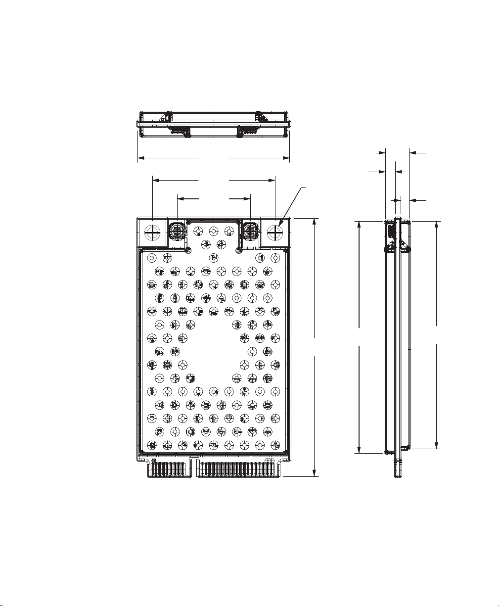
2.6 (2 places)
4.78
30.00
45.84
14.40
24.20
50.95
44.94
2.40
1.35
The module fits within the MiniPCI Express specifications. For
physical dimensions, see the illustration.
IM11 RFID Reader Module Physical Specifications: 50.95 mm long x 30 mm
wide x 4.78 mm thick. Exceptions to the MiniPCI Express form factor: top shield
side thickness is 2.4 mm (instead of 2.01 mm) and bottom shield side thickness
is 1.35 mm (instead of 1.75 mm).
14 IM11 RFID Reader Module Integration Guide (Confidential)
Page 15

About the Connectors
The module mounts on a PC board and connects to it using a miniPCI connector, P/N JAE MM60-52B1-E1 or equivalent. Intermec
recommends using the higher profile connector, because the low
profile connector does not fit flush to the PCB with the low profile
connection.
The antenna receptacle is a Hirose U.FL connector (50 ohm, coaxial).
Supported Antennas
The module has been tested to work with a variety of antenna types.
Antenna systems, combination antenna and cables, are restricted to
+6 dBi linear gain in North, Central, and South America. Europe have
a maximum antenna system gain restriction of 2 Watt effective
radiated power.
Radio communications regulatory agencies in each country has
restrictions for antenna gain or transmitter power. Consult with your
Intermec OEM Sales Representative or Professional Wireless /RFID
Installer for details.
These antennas are approved to work with the IM11:
• Antenna primary linear (0 dBi linear, omni)
• PIFA omni yagi (5.5 dBi linear)
• Ceramic patch antenna (2.5 dBi, circular polarized)
• Cross polar linear (dual pole antenna)
• High gain circular polarized panel 11 dBiC (8 dBi linear)
• High gain linear panel (8 dBi)
• RFID printer coupler (-30 dBi)
• NeWave N7 (5.5 dBi, multi axis dipole)
Note: To use the 8 dBi antennas, the module integrator needs to
reduce the output power to 29 dBm.
You can use any antenna with similar construction to one of the
approved antennas, as long as it has equal or less gain. The module
integrator is responsible for final regulatory approvals.
IM11 RFID Reader Module Integration Guide (Confidential) 15
Page 16

Operating Modes
Overtemperature Mode Standard Mode
IM11 is in Idle mode.
IM11 receives
a request for a tag
operation from an
application.
Is the IM11
temperature
<85 °C?
The IM11's ability to return
to normal status depends
on the ability of the card to
dissipate the heat.
The IM11 is designed to
operate at 1 Watt of
continuous power between
-20 °C and +60 °C. These
limits are not user
programmable.
IM11 API returns
“Status=Normal"
and data, if found.
Application checks reason
for failed status and returns
overtemperature condition.
IM11 API returns
"Status=Failed."
IM11 receives
a request for a tag
operation from an
application
No
No
Ye s
Ye s
This illustration shows the module Overtemperature and Standard
operating modes.
16 IM11 RFID Reader Module Integration Guide (Confidential)
The module has a temperature sensor. If overtemperature is detected
(nominally 85 °C), the module sends an overtemperature message. No
RF output occurs until the temperature falls below the recovery
threshold (nominally 75 °C).
Page 17

In most situations, Overtemperature mode adequately protects the
module against very high temperatures. However, if you use the
module in a high duty-cycle operation for extended periods of time at
elevated temperatures, you may want to attach a heatsink to the
perforated top shield of the IM11. For proper placement, refer to the
illustration of the page 14
For optimal thermal performance, connect the top shield of the
module to a metal surface with good air flow or access to the lower
temperature case exterior. To connect these surfaces, use a low
thermal resistance material, such as themal grease or a thermallyconductive spacer.
Electrical Integration
The module communicates either over USB or through serial:
• The USB client communication follows the CDC profile (a
Microsoft standard driver) and is USB 2.0-compliant, operating at
12 Mbps (full speed). For more information, see “Open a USB
Connection” on page 32.
• In Serial mode, the module communicates as a standard PC COM
port, operating at 115.2 Kbps. It has eight general purpose inputs
and outputs for monitoring and controlling external signals. For
more information, see “Open a Serial Connection” on page 31.
A Digital Signal Processor (DSP) controls the radio functions and
provides communication with the host. This interface allows direct
reprogramming and updating of the on-board FLASH memory. It has
64 MB of DDR and 4 MB of SPI FLASH available.
Power Requirements
The module operates off power input from 3.15 VDC to 5.2 VDC. If
the input is 3.3 V DC or less, you must account for significant
increased current demand. If the input drops below 3.15 VDC, 1 Watt
output is not possible.
IM11 RFID Reader Module Integration Guide (Confidential) 17
Page 18

The module handles its own power management and goes into
Standby mode automatically when there are no outstanding
commands. However, even in Standby mode, the IM11 immediately
responds to host activity, eliminating any potential host timeout
conditions.
To achieve an even lower power Standby mode, the host needs to
support USB suspend and remote wakeup.
To reduce power, the module duty cycles its transmitter. The duty
cycling happens according to the read commands that the application
executes. To achieve the lowest power, after all tags are read, the
transmitter turns off. After a period of time, the transmitter activates
to identify new tags in the field. After all new tags are read, the
transmitter turns off for the rest of the period.
Also, the module automatically reduces the power out if the input
voltage is too low or the temperature of the module is too high.
For more information about low power read commands, see the Basic
Reader Interface Programmer Reference Manual.
Reader Power States
There are four different power states for the RFID module.
Reader Power States and Levels of Consumption
Power State Level of Consumption
Off 0 (3.3 V turned off to the module)
Deep Sleep
• 3.3 V on
• RF enable = Off
• < 1 mA
• Real Time Clock (RTC) = On (< 100 μA to power RTC)*
• Enable (Pin 20) is low
Idle
• 3.3 V on
• RF enable = On
• No USB activity
• About 35 mA
• Enable (Pin 20) is high
Read Max current during tag read about 1.5 A
18 IM11 RFID Reader Module Integration Guide (Confidential)
Page 19

* You cannot turn off the RTC unless you remove power Pin 2
(VBATT) on the mini-PCI connector.
Transition Times Between Reader Power States
Transition State Trans i tio n Tim e
Off to Deep Sleep 100 ms
Deep Sleep to Tag Read < 6 ms*
Idle to Tag Read
* < 6 ms required to load the software to load the module. After loading the
software, the module stays idle (~110 mW) until a read is requested. When a
read is finished, the unit returns to idle. Duty cycling is employed to quiet
tags that have already been read and to ensure the host system transmitter
does not stay on all the time.
Reader Power Draw
This section explains the power draw of the IM11 under various
operating conditions. These are the four tests that were conducted:
• Time for USB device to respond to USB
wakeup is about 10 ms.
• Time for serial to respond is about 100 ms for a
10 byte command will take 100 ms at 115.2
kbps.
• Test A: READ REPORT=EVENT: This test uses default values
and starts a continuous read. It takes advantage of the duty cycle
to save power, and resets the tags after every inventory round so
the tags keep responding.
• Test B: ATTRIB UNSELTRIES=0, READ REPORT=EVENT:
This test uses the default values of the reader except for
UNSELTRIES. The continues read takes advantage of the duty
cycle to save power. Setting UNSELTRIES=0 prevents the reader
from resetting the tags. After the initial inventory round, the tags
remain quiet until session 2 persistence wears off. This is the
recommended configuration for reading large tag populations in
continuous mode.
IM11 RFID Reader Module Integration Guide (Confidential) 19
Page 20

• Test C: Repeated READ: This test uses the default values of the
reader and repeatedly issues a single READ command, and does
not allow the reader to duty cycle the radio. The tags are reset at
the beginning of every inventory round so they can respond to
every read command.
• Test D: ATTRIB UNSELTRIES=0, Repeated READ: This test is
the same as Test C, but UNSELTRIES is set to 0. The tags respond
the first time and then only responds when their persistences
wears off.
Supply Voltage 3.35 V
Conducted Quad Tag, 20 dB Antennuation
Field Strength Te s t A Tes t B Test C Test D
30 dB 153 72 536 354
27 dB 124 65 420 296
24 dB 110 61 348 260
21 dB 96 59 302 234
18 dB 60 57 272 220
15 dB 55 56 251 217
Supply Voltage 3.35 V
Radiated,50 Tags Cardboard Box in Front of Antenna
Field Strength Te s t A Tes t B Test C Test D
30 dB 490 124 950 378
27 dB 290 96 616 303
24 dB 182 74 451 265
21 dB 110 64 337 238
18 dB 83 58 266 222
15 dB 79 58 264 220
20 IM11 RFID Reader Module Integration Guide (Confidential)
Page 21

Supply Voltage 4.45 V
Conducted Quad Tag, 20 dB Anttenuation
Field Strength Te s t A Tes t B Test C Test D
30 dB 456 57 369 252
27 dB 101 54 299 214
24 dB 88 52 252 193
21 dB 78 49 223 173
18 dB 49 49 204 164
15 dB 49 49 188 162
BRI, Default Attributes, 32 Conducted Tags, READ: The long, flat CW period
after the inventroy round is caused when the BRI repoprts the tags before
shutting off RF.
IM11 RFID Reader Module Integration Guide (Confidential) 21
Page 22

BRI, Default Attributes, 32 Conducted Tags, READ REPORT=EVENT: All tags
respond every time.
BRI, Default Attributes, ATTRIB UNSELTRIES=0, 32 Conducted Tags, READ
REPORT=EVENT: UNSELTRIES=0 causes the tags to remain quiet, they rarely
respond after the first time.
Mini-PCI Connector Pin Descriptions
Pin Descriptions
Pin Pin Name Description
1 Reserved Do NOT connect
2 +V_BATT Power input
3 Reserved Do NOT connect
4GND Ground
22 IM11 RFID Reader Module Integration Guide (Confidential)
Page 23

Pin Descriptions (continued)
Pin Pin Name Description
5 No Connect Not connected
6GPIO2
7 No Connect Not connected
8 No Connect Not connected
9GND Ground
10 No Connect Not connected
11 No Connect Not connected
12 No Connect Not connected
13 Reserved Do NOT connect
14 No Connect Not connected
15 GND Ground
16 GPIO0
17 Reserved Do NOT connect
18 GND Ground
19 Reserved Do NOT connect
20 ENABLE Input. Logic high level turns on
power to IM11
21 GND Ground
22 UART_SEL_L Input. Low level activates UART
instead of USB (at Enable active)
23 Reserved Do NOT connect
24 +V_BATT Power input
25 Reserved Do NOT connect
26 GND Ground
27 GND Ground
28 GPIO1
29 GND Ground
30 GPIO3
31 Reserved Do NOT connect
32 GPIO4
33 RESET_L Logic low level resets IM11
34 GND Ground
IM11 RFID Reader Module Integration Guide (Confidential) 23
Page 24

Pin Descriptions (continued)
Pin Pin Name Description
35 GND Ground
36 USB_DM USB data minus
37 GND Ground
38 USB_DP USB data plus
39 +V_BATT Power input
40 GND Ground
41 +V_BATT Power input
42 No Connect Not connected
43 GND Ground
44 GPIO5
45 HOST_CTS1 Future use
46 GPIO6
47 HOST_RTS1 Future use
48 GPIO7
49 HOST_RX1 Output. Rx data output to host
50 GND Ground
51 HOST_TX1 Input. Tx data input from host
52 +V_BATT Power input
Notes:
• GPIOx: General purpose inputs/outputs. The pins are high
impedance inputs when initially powered, following a module
reset. You can configure all pins as inputs or outputs under
software control.
• Host TX1/RX1 and host RTS1/CTS1: Standard logic levels. No
RS-232 transceiver.
• USB_DP: If UART_SEL_L is low, pull up to wake up. If logic level
is low, IM11 is in Sleep mode.
• All signals are 3.3 V logic levels (5 V tolerant inputs).
24 IM11 RFID Reader Module Integration Guide (Confidential)
Page 25

Input and Output Voltage Level Descriptions
Voltage Levels
Low High Notes
Inputs
Outputs
Auxiliary outputs are 3-state inputs (high impedance) on power-up
until they are written to for the first time. You should provide pullups
or pulldowns to keep any external logic disabled during this
condition.
0 to 0.8 V 2.4 to 5.5 V ± 10 μA max input current
0.4 V max @ 4 mA 2.9 V min @ -4 mA
IM11 RFID Reader Module Integration Guide (Confidential) 25
Page 26

Transient
protection
LED
VBatt
VBatt
Input
10 to 100K
GP Output
GP Output
V Ext.
Output
GPI
Input is driven high to
activate FET Sw to pull
the GPI line low.
GPO is driven high to
activate FET Switch to
drive Output low.
Typical output circuit.
GPO is driven low to
activate FET switch to
turn on LED.
Transmit Power
26 IM11 RFID Reader Module Integration Guide (Confidential)
Typical I/O Circuits
The module is able to adjust transmit power from 29.5 dBm to
10.5 dBm, configurable in 1 dBm steps with an accuracy (the measure
of the power output for each level) of +/-0.5 dBm. The initial tolerance
(the measure of the power output for each level) is +/-0.5 dBm. The
output power is set on each of the antennas. Output power tolerance
from the nominal setting is +/- 0.75 dBm over an ambient
temperature range of -20 °C to 60 °C.
The module supports PR-ASK modulation for EPC Class 1 Gen 2 tags
only.
Page 27

RF Integration
The module supports two antenna connections. You can use software
to control the selection of either connection. The module switches
from one antenna to the other in 5 ms or less. The switching time is
defined from the 90% power point as the RF is turned off at the first
port to the 90% power point as the RF is turned on at the second port.
The module uses an integrated RFID transceiver. It features
autotuning on the antenna ports to match the antenna return loss
dynamically. The system compensates for antennas with a VSWR of
2.0 or lower (a VSWR of <1.7 is optimum).
There are no termination requirements for the antenna ports. The
module will not transmit to any open antenna ports.
Software Integration
In Serial mode, the module appears as a standard PC COM port. It has
eight general purpose inputs and outputs. You can use a
communications program, such as HyperTerminal, to communicate
with the module using the Basic Reader Interface (BRI). For more
information, see the Basic Reader Interface (BRI) Programmer
Reference Manual.
BRI Command Default Values
Command Default Value
ANTS 1
ANTTIMEOUT 50
ANTTRIES 3
BROADCASTSYNC 0
CHKSUM OFF
DENSEREADERMODE ON
ECHO OFF
EPCC1G2PARAMETERS 16
FIELDSEP ASCII space character (0x20)
FIELDSTRENGTH 30dB, 30dB
IDREPORT OFF
IM11 RFID Reader Module Integration Guide (Confidential) 27
Page 28

BRI Command Default Values (continued)
Command Default Value
IDTIMEOUT 100
IDTRIES 1
INITIALQ 4
INITTRIES 1
LOCKTRIES 3
NOTAGRPT OFF
QUERYSEL (new) 4
QUERYTARGET (new) A
RDTRIES 3
RPTTIMEOUT 0
SCHEDULEOPT 0
SELTRIES 1
SESSION 2
TAGTYPE EPCC1G2
TIMEOUTMODE OFF
TTY OFF
UNSELTRIES 1
UTCTIME 0
WRTRIES 3
From the Intermec website, you can also download a sample
application (JRFID) to test, configure, and control the module.
To download the JRFID application
1 Go to www.intermec.com.
2 Click Products > RFID > Fixed Readers > IF2.
3 Click the Downloads tab.
4 Under Demo Software, download the JRFID Application.
28 IM11 RFID Reader Module Integration Guide (Confidential)
Page 29

About the Development Kit
The development kit comes with all the necessary hardware to
connect it to your desktop PC. The kit contains:
• IM11 RFID Reader Module
• Development board
• Antenna and cables
• Power supply
• USB cable
• Serial cable
• RFID tags
• CD that contains software tools and this guide
Once connected, open a serial or USB connection to setup, test,
configure, and control the module.
IM11 RFID Reader Module Integration Guide (Confidential) 29
Page 30

SW1
SW2
SW3 CN19
COM 1
USB port
Antenna port 1
Antenna port 2
Antenna cables
COM 2
IM11 Development Board: The default settings for the switches and jumpers.
30 IM11 RFID Reader Module Integration Guide (Confidential)
Page 31

Connect the Development Kit
You can connect the development kit to your PC through serial or
USB communications and use it to perform these tasks:
• Establish a BRI session.
• Use the JRFID application.
• Restore default settings.
Open a Serial Connection
Use a serial communications program, such as Hyperterminal, to
communicate with the module.
Note: If you do not have a communications program, you can
download a trial version of HyperTerminal for Windows 7 at
www.hilgraeve.com/hyperterminal.
To open a serial connection
1 If you have Microsoft ActiveSync running on your desktop PC,
disable ActiveSync to make the serial port available.
2 Connect the RFID module and antenna cables to the development
board.
3 Connect the antenna to the first antenna port.
4 Connect the serial cable from the COM 1 port on the development
board to the serial port on your PC.
5 Start the communications program.
6 Configure the communications parameters to:
• Bits per second: 115200
• Data bits: 8
• Parity: None
• Stop bit: 1
• Flow control: None
• Send line ends with line feeds: Enabled
IM11 RFID Reader Module Integration Guide (Confidential) 31
Page 32

7 Connect the development kit to power. The development kit boots
as soon as you apply power. In about a minute, the message
“Loading System” appears as the development kit initializes.
The serial connection is established.
Open a USB Connection
If you are opening a USB connection, you need to create a folder that
includes a gserial.inf and a usbser.sys file.
To open a USB connection
1 On your desktop PC, create a new folder.
2 Click Start > Programs > Accessories > Notepad.
3 In Notepad, copy and paste this text:
[Version]
Signature="$Windows NT$"
Class=Ports
ClassGuid={4D36E978-E325-11CE-BFC1-08002BE10318}
Provider=%LINUX%
DriverVer=08/17/2004,0.0.2.0
; Copyright(C)2004 Al Borchers (alborchers@steinerpoint.com)
[Manufacturer]
%LINUX%=GSerialDeviceList
[GSerialDeviceList]
%GSERIAL%=GSerialInstall, USB\VID_0525&PID_A4A7
[DestinationDirs]
DefaultDestDir=10,System32\Drivers
[GSerialInstall]
CopyFiles=GSerialCopyFiles
32 IM11 RFID Reader Module Integration Guide (Confidential)
Page 33

AddReg=GSerialAddReg
[GSerialCopyFiles]
usbser.sys
[GSerialAddReg]
HKR,,DevLoader,,*ntkern
HKR,,NTMPDriver,,usbser.sys
HKR,,EnumPropPages32,,"MsPorts.dll,SerialPortPropPageProvider"
[GSerialInstall.Services]
AddService = usbser,0x0002,GSerialService
[GSerialService]
DisplayName = %GSERIAL_DISPLAY_NAME%
ServiceType = 1 ; SERVICE_KERNEL_DRIVER
StartType = 3 ; SERVICE_DEMAND_START
ErrorControl = 1 ; SERVICE_ERROR_NORMAL
ServiceBinary = %10%\System32\Drivers\usbser.sys
LoadOrderGroup = Base
[Strings]
LINUX = "Linux"
GSERIAL = "Gadget Serial"
GSERIAL_DISPLAY_NAME = "USB Gadget Serial Driver"
4 Click File > Save As.
5 Browse to the folder you created in Step 1 and save the document
as gserial.inf.
6 Browse to the C:\Windows\Driver Cache\i386 directory and locate
the driver.cab file.
7 Open the driver.cab file with a .cab extraction tool, find the
usb.sys file, and copy it tothe folder you created in Step 1.
8 Connect the RFID module and antenna cables to the development
board.
9 Connect the antenna to the first antenna port.
10 Connect the USB cable from the USB port on the development
board to the USB port on your PC. The Found New Hardware
Wizard appears.
11 Select Install from a list or specific location (Advanced), and
click Next.
IM11 RFID Reader Module Integration Guide (Confidential) 33
Page 34

12 Select Include this location in the search, browse to the folder
you created in Step 1, and press Enter.
13 When the Windows Logo Testing screen appears, click Continue
Anyway . The development kit is connected through USB.
Troubleshooting
Use the information in this section to fix problems with the IM11
module.
Problems While Working with RFID
Many problems you may encounter when working with your RFID
system can be solved by carefully checking the RFID settings and
changing them accordingly.
RFID Problems and Solutions
Problem Solution
You cannot connect to the module
using the serial port.
The module is unable to read RFID
tags, or seems to read tags slow or
inconsistently.
• Verify that you are using a null-modem cable to
connect to the desktop PC.
• Verify that you are communicating through the correct
serial port.
• Verify that your PC is set to 115200, N, 8, 1, no flow
control.
Check these conditions:
• Your RFID antennas must be connected correctly to the
module and mounted in optimum locations. Make sure
all antenna connections are tight and that the cables
are in good condition.
• To maximize performance, make sure you have chosen
the correct tag types.
34 IM11 RFID Reader Module Integration Guide (Confidential)
Page 35

Restore Default Settings
If you are having problems with the module, you can use a serial
connection to restore the default settings to the module.
To restore the module default settings
1 open a serial connection to the module. For help, see “Open a
Serial Connection” on page 31.
2 In the login field, type restore_defaults, and then press
Enter. The module reboots and the default settings are restored.
DIP Switch Default Settings
If you are having problems with the module or development board,
you may need to reset the dip switches back to their default settings.
1
10
SW1 DIP Switch Default Settings
SW1 DIP Switch Default Settings
Dip Switch Description Default Setting
1 EN HEADSET DET Disabled
2 EN BUTTON DET Disabled
3 EN GRN LED Enabled
4 EN RED LED Disabled
IM11 RFID Reader Module Integration Guide (Confidential) 35
Page 36

SW1 DIP Switch Default Settings (continued)
1 4
Dip Switch Description Default Setting
5 EN M10 LED Enabled
6 EN UART 1 RTS/CTS Disabled
7 EN UART 1 R1/CD/DTR/DSR Disabled
8 EN UART 1 XCVR Enabled
9 EN UART 3 XCVR Disabled
10 DISABLE MODEM Enabled
36 IM11 RFID Reader Module Integration Guide (Confidential)
SW4 DIP Switch Default Settings
SW4 DIP Switch Default Settings
Dip Switch Description Default Setting
1 EN FIXED OUTPUT 3.3 V On
2 EN BARREL JACK LDO On
3 MODEM - 2.6 V Off
4 LDO 2.6 V On
Page 37

SW3 DIP Switch Default Settings
1 4
SW3 DIP Switch Default Settings
Dip Switch Description Default Setting
1 EN MIC_P GAIN + 20 dB On
2 EN MIC_N GAIN + 20 dB On
3 EN MIC_P BYPASS Off
4 EN MIC_N BYPASS Off
IM11 RFID Reader Module Integration Guide (Confidential) 37
Page 38

J4 Jumper Default Setting
Jumper
J4 Jumper Default Setting
Jumper Installed Description Default Setting
Yes VCC_3.3 V On
38 IM11 RFID Reader Module Integration Guide (Confidential)
Page 39

Page 40

Federal Communication Commission Interference Statement
This device complies with Part 15 of the FCC Rules. Operation is subject to the following two conditions: (1)
This device may not cause harmful interference, and (2) this device must accept any interference received,
including interference that may cause undesired operation.
This equipment has been tested and found to comply with the limits for a Class B digital device, pursuant to
Part 15 of the FCC Rules. These limits are designed to provide reasonable protection against harmful
interference in a residential installation. This equipment generates, uses and can radiate radio frequency
energy and, if not installed and used in accordance with the instructions, may cause harmful interference to
radio communications. However, there is no guarantee that interference will not occur in a particular
installation. If this equipment does cause harmful interference to radio or television reception, which can
be determined by turning the equipment off and on, the user is encouraged to try to correct the interference
by one of the following measures:
- Reorient or relocate the receiving antenna.
- Increase the separation between the equipment and receiver.
- Connect the equipment into an outlet on a circuit different from that
to which the receiver is connected.
- Consult the dealer or an experienced radio/TV technician for help.
FCC Caution: Any changes or modifications not expressly approved by the party responsible for compliance
could void the user's authority to operate this equipment.
This transmitter must not be co-located or operating in conjunction with any other antenna or transmitter.
Radiation Exposure Statement:
This equipment complies with FCC radiation exposure limits set forth for an uncontrolled environment. This
equipment should be installed and operated with minimum distance 20cm between the radiator & your body.
This device is intended only for OEM integrators under the following conditions:
1) The antenna must be installed such that 20 cm is maintained between the antenna and users.
2) The transmitter module may not be co-located with any other transmitter or antenna.
As long as 2 conditions above are met, further transmitter test will not be required. However, the OEM
integrator is still responsible for testing their end-product for any additional compliance requirements
required with this module installed
IMPORTANT NOTE: In the event that these conditions can not be met
(for example certain laptop
configurations or co-location with another transmitter), then the FCC authorization is no longer considered
valid and the FCC ID can not be used on the final product. In these circumstances, the OEM integrator will
Page 41

be responsible for re-evaluating the end product (including the transmitter) and obtaining a separate FCC
authorization.
End Product Labeling
This transmitter module is authorized only for use in device where the antenna may be installed such that 20
cm may be maintained between the antenna and users. The final end product must be labeled in a visible
area with the following: “Contains FCC ID: HD5-IM11PRT”. The grantee's FCC ID can be used only when all
FCC compliance requirements are met.
Manual Information To the End User
The OEM integrator has to be aware not to provide information to the end user regarding how to install or
remove this RF module in the user’s manual of the end product which integrates this module.
The end user manual shall include all required regulatory information/warning as show in this manual.
Industry Canada statement:
This device complies with ISED’s licence-exempt RSSs. Operation is subject to the following two
conditions: (1) This device may not cause harmful interference, and (2) this device must accept any
interference received, including interference that may cause undesired operation.
Le présent appareil est conforme aux CNR d’ ISED applicables aux appareils radio exempts de licence.
L’exploitation est autorisée aux deux conditions suivantes : (1) le dispositif ne doit pas produire de
brouillage préjudiciable, et (2) ce dispositif doit accepter tout brouillage reçu, y compris un brouillage
susceptible de provoquer un fonctionnement indésirable.
Radiation Exposure Statement:
This equipment complies with ISED radiation exposure limits set forth for an uncontrolled environment.
This equipment should be installed and operated with minimum distance 20cm between the radiator & your
body.
Déclaration d'exposition aux radiations:
Cet équipement est conforme aux limites d'exposition aux rayonnements ISED établies pour un
environnement non contrôlé. Cet équipement doit être installé et utilisé avec un minimum de 20 cm de
distance entre la source de rayonnement et votre corps.
DETACHABLE ANTENNA USAGE
This radio transmitter (IC: 1639B-IM11PRT/ Model: IM11-PRT) has been approved by ISED to operate
with the antenna type listed below with maximum permissible gain indicated. Antenna types n
ot included in
this list, having a gain greater than the maximum gain indicated for that type, are strictly prohibited for use
with this device.
Le présent émetteur radio (IC: 1639B-IM11PRT/ Model: IM11-PRT) a été approuvé par ISED pour
onctionner avec les types d'antenne énumérés ci-dessous et ayant un gain admissible maximal. Les types
f
Page 42

d'antenne non inclus dans cette liste, et dont le gain est supérieur au gain maximal indiqué, sont strictement
interdits pour l'exploitation de l'émetteur.
Approved antenna(s) list
Type Gain Brand Manufacturer
near-field -30dBi Honeywell Honeywell
This device is intended only for OEM integrators under the following conditions: (For module device use)
1) The antenna must be installed such that 20 cm is maintained between the antenna and users.
2) The transmitter module may not be co-located with any other transmitter or antenna.
As long as 2 conditions above are met, further transmitter test will not be required. However, the OEM
integrator is still responsible for testing their end-product for any additional compliance requirements
required with this module installed.
Cet appareil est conçu uniquement pour les intégrateurs OEM dans les conditions suivantes: (Pour utilisation
de dispositif module)
1) L'antenne doit être installée de telle sorte qu'une distance de 20 cm est respectée entre l'antenne et les
utilisateurs, et
2) Le module émetteur peut ne pas être coïmplanté avec un autre émetteur ou antenne.
Tant que les 2 conditions ci-dessus sont remplies, des essais supplémentaires sur l'émetteur ne seront pas
nécessaires. Toutefois, l'intégrateur OEM est toujours responsable des essais sur son produit final pour toutes
exigences de conformité supplémentaires requis pour ce module installé.
IMPORTANT NOTE:
In the event that these conditions can not be met (for example certain laptop configurations or co-location
with another transmitter), then the Canada authorization is no longer considered valid and the IC ID can not
be used on the final product. In these circumstances, the OEM integrator will be responsible for
re-evaluating the end product (including the transmitter) and obtaining a separate Canada authorization.
NOTE IMPORTANTE:
Dans le cas où ces conditions ne peuvent être satisfaites (par exemple pour certaines configurations
d'ordinateur portable ou de certaines co-localisation avec un autre émetteur), l'autorisation du Canada n'est
plus considéré comme valide et l'ID IC ne peut pas être utilisé sur le produit final. Dans ces circonstances,
l'intégrateur OEM sera chargé de réévaluer le produit final (y compris l'émetteur) et l'obtention d'une
autorisation distincte au Canada.
End Product Labeling
This transmitter module is authorized only for use in device where the antenna may be installed such that 20
cm may be maintained between the antenna and users. The final end product must be labeled in a visible
area with the following: “Contains IC: 1693B-IM11PRT”.
Page 43

Plaque signalétique du produit final
Ce module émetteur est autorisé uniquement pour une utilisation dans un dispositif où l'antenne peut être
installée de telle sorte qu'une distance de 20cm peut être maintenue entre l'antenne et les utilisateurs. Le
produit final doit être étiqueté dans un endroit visible avec l'inscription suivante: "Contient des IC:
1693B-IM11PRT".
Manual Information To the End User
The OEM integrator has to be aware not to provide information to the end user regarding how to install or
remove this RF module in the user’s manual of the end product which integrates this module.
The end user manual shall include all required regulatory information/warning as show in this manual.
Manuel d'information à l'utilisateur final
L'intégrateur OEM doit être conscient de ne pas fournir des informations à l'utilisateur final quant à la façon
d'installer ou de supprimer ce module RF dans le manuel de l'utilisateur du produit final qui intègre ce
module.
Le manuel de l'utilisateur final doit inclure toutes les informations réglementaires requises et avertissements
comme indiqué dans ce manuel.
Page 44

Worldwide Headquarters
6001 36th Avenue West
Everett, Washington 98203
U.S.A.
tel 425.348.2600
fax 425.355.9551
www.intermec.com
© 2013 Intermec Technologies
Corporation. All rights reserved.
IM11 RFID Reader Module Integration Guide
*944-637-001*
P/N 944-637-001
 Loading...