

Honeywell IGSMHS4G Installation And Setup Manual

IInntteelllliiPPaatth
h
AAuuttoo--sseelleeccttss OOppttiimmuumm GGSSMM ppaatthh –– 22GG,, 33GG,, oorr 44G
M
TTM
SSeerriieess 44GG GGSSMM CCoommmmuunniiccaattoorr
G
GSS
IIG
HHiigghh SSeeccuurriittyy IInntteerrnneett aanndd GGSSMM CCoommmmuunniiccaattoorr
M
M
HSS44
H
G
G
Installation and Setup Guide
800-10915V1 8/13 Rev. A


Table of Contents
• • • • • • • • • • • • • • • • • • • • • • • • • • • • • • • • • • • • • • • • • • • • • • • • •
SECTION 1: General Information ........................................................................................................... 1-1
System Overview ...................................................................................................................................... 1-1
Introduction ....................................................................................................................................... 1-1
General Information .......................................................................................................................... 1-1
System Features ....................................................................................................................................... 1-2
About AlarmNet-i Internet Application ................................................................................................. 1-2
Encryption ................................................................................................................................................ 1-2
Modes of Operation .................................................................................................................................. 1-2
ECP Mode ........................................................................................................................................... 1-2
Zone Trigger Mode ............................................................................................................................. 1-3
4204 Mode and Two-4204 Mode ....................................................................................................... 1-3
Supervision Features ............................................................................................................................... 1-3
Antenna .............................................................................................................................................. 1-4
Specifications ............................................................................................................................................ 1-4
Compatibility ............................................................................................................................................ 1-5
SECTION 2: Mounting and Wiring .......................................................................................................... 2-1
Determine the Signal Strength and Select a Location .......................................................................... 2-1
Mounting the Communicator .................................................................................................................. 2-2
Wiring the Communicator ....................................................................................................................... 2-3
Wiring for ECP, 4204 and Two-4204 Modes .................................................................................... 2-3
Wiring for Zone Trigger Mode .......................................................................................................... 2-4
Wiring the Fault Relay ...................................................................................................................... 2-5
Internet Connection ........................................................................................................................... 2-5
Power Connections and Options ............................................................................................................. 2-6
Powering the Communicator ............................................................................................................ 2-6
Backup Battery Connection .............................................................................................................. 2-6
Initial Power-Up Sequence ............................................................................................................... 2-7
SECTION 3: Programming the Communicator ................................................................................... 3-1
General Information ................................................................................................................................ 3-1
Programming the Control Panel to work with the IGSMHS4G ..................................................... 3-1
Using the AlarmNet Direct Website ................................................................................................ 3-2
Using a 7720P Programming Tool .................................................................................................... 3-2
Using the Control Panel Programming Mode ................................................................................. 3-3
Programming Conventions ............................................................................................................... 3-3
ECP Mode Programming ......................................................................................................................... 3-3
ECP Status Codes .............................................................................................................................. 3-8
Alternative Modes (Zone Trigger, 4204 and Two-4204) ........................................................................ 3-9
Zone Trigger Mode ............................................................................................................................. 3-9
4204 Emulation Mode ....................................................................................................................... 3-9
4204 Emulation Mode Options ....................................................................................................... 3-10
Alternative Mode Programming ........................................................................................................... 3-11
Exiting Programming Mode .................................................................................................................. 3-20
Setting Factory Defaults ........................................................................................................................ 3-20
SECTION 4: Registration .......................................................................................................................... 4-1
Registering the Communicator ............................................................................................................... 4-1
Register through the AlarmNet Direct Website .............................................................................. 4-1
Register using the Tamper Switch ................................................................................................... 4-2
Register using the Programming Tool ............................................................................................. 4-2
i

IGSMHS4G Installation and Setup Guide
Replacing an existing communicator ............................................................................................... 4-3
Register by Phone .............................................................................................................................. 4-4
SECTION 5: Programmer Keyboard Commands ................................................................................. 5-1
Identification Displays ............................................................................................................................. 5-1
GSM Status Displays ............................................................................................................................... 5-2
System Status Displays ........................................................................................................................... 5-4
SECTION 6: Network Diagnostics ........................................................................................................... 6-1
Running Network Diagnostics ................................................................................................................ 6-1
Possible Errors Running Network Diagnostics ...................................................................................... 6-2
Appendices ................................................................................................................................................... A-1
Appendix A : Summary of LED Operation ............................................................................................. A-1
Appendix B : Central Station Messages ................................................................................................. B-1
Appendix C : Glossary .............................................................................................................................. C-1
Summary of Connections Diagram……………………………………..………………...Inside Back Cover
ii

SECTION 1
General Information
• • • • • • • • • • • • • • • • • • • • • • • • • • • • • • • • • • • • • • • • • • • • • • • • •
System Overview
Introduction
Congratulations on your purchase of Honeywell's IGSMHS4G High Security Internet and
GSM Communicator (henceforth referred to as IGSMHS4G). It represents the latest and
most innovative communication technology for the security industry and uses the most
sophisticated encryption to ensure the highest level of security for your customer.
The new 4G connectivity brings faster GSM data transfers with lower latency (response
time); together it results in speedier data transfers.
The communicator requires an AlarmNet–i account. For new installations, please obtain
the account information from the central station prior to programming this communicator.
For detailed information about enrolling the communicator and replacing communicators,
refer to the AlarmNet Direct Online Help Guide.
In addition to alarm reporting, the communicator provides upload/downloading capability of
Honeywell's control panel data over the Internet (via the AlarmNet-G network), using GSM
(Global System for Mobile) technology.
General Information
The IGSMHS4G communicates via the Internet (when service is available) and switches to
GSM service when the Internet is not available.
In normal operation (with Internet connectivity), the IGSMHS4G communicates from your
customer's network connection to the Honeywell Network Operations Center, (NOC) via the
AlarmNet-i network. The NOC receives data and routes the information to the Central
Station of your choice, based on the account number you assign to the communicator. Note
that your Central Station needs to give you the account number. The same account number
is used for both Internet and GSM transmissions. If your current Central Station is capable
of receiving signals from the Honeywell NOC, they are capable of receiving signals from the
communicator.
If, for some reason, Internet connectivity is not available, (for example, your customer's ISP
is off line or disconnected), the communicator will transmit signals via the AlarmNet-G
(GSM) cellular network, which uses the GPRS (General Packet Radio Service) to complete
these transmissions. These transmissions are sent to the Honeywell NOC and then
forwarded to your Central Station exactly the same way as if they were received via the
Internet.
If the Internet and
GPRS (part of the GSM cellular network) are both unavailable (fail), the
message will not be sent from this communicator.
For maximum reliability, it is recommended the device be operated in dual path
mode with Internet and GSM both enabled and connected.
1-1

IGSMHS4G Installation and Setup Guide
UL
UL
System Features
Basic features include:
• Supports dynamic or static IP addressing, and installs behind firewalls without
compromising network security.
• Quick connection to compatible Honeywell series control panels
• Simple programming using a 7720P programming tool
• Reports fire (Fire has not
Internet
• Reports messages via AlarmNet-G as backup to Internet reporting
• Allows uploading and downloading of control panel data over the Internet.
been evaluated by UL), burg, and status messages via the
About AlarmNet-i Internet Application
AlarmNet-i is a fully encrypted, secure method of delivering alarm messages from a
protected premise to an AlarmNet equipped central station. The internet communicator
transmits status, supervisory, and alarm messages to the AlarmNet Control Center using a
broadband Internet connection.
The AlarmNet Control Center identifies, validates, and forwards the messages to the
appropriate AlarmNet central station. AlarmNet-i has an unlimited account capacity.
Encryption
The communicator uses 256 bit AES (Rijndael) encryption (which is required for certain
government installations). The AlarmNet-i AES Encryption Software Module Version 1.0
contained in the Honeywell products has NIST approval. Listings for this approval can be
found at http://csrc.nist.gov/cryptval/aes/aesval.html and search for “Certification number
127.”
UL
Modes of Operation
The communicator provides four modes of operation so it can be used with various types of
control panels, as summarized below.
ECP Mode
• This mode is for use with Honeywell control panels that support ECP communication
• The communicator connects to the control panel’s keypad terminals and provides 2-way
communication with the control panel using ECP messaging
• The control panel treats the communicator as an ECP device, so ensure to program the
control panel with the communicator’s device address
• Reports are sent in Contact ID format
• The communicator also supports two hardwire zone trigger inputs (zones 6 and 7)
Options include; V+, V–, EOL, inverted, and non-inverted.
UL – For the communicator, only the V+ inverted, V– non-inverted, and EOL options have
been evaluated.
The IP and GSM signaling paths are suitable for encrypted line security when programmed for
1 minute IP/GSM Fault Times. The system configurations are not suitable as a Dual Line
Signal transmission system.
Only ECP Mode and Zone Trigger modes have been approved for UL installations.
Opening and Closing ring back is fully supported.
1-2

Section 1: General Information
UL
UL
Zone Trigger Mode
• This mode is for use with control panels that do not support ECP communication nor 4204
Relay Modules
• The communicator provides six input zones and each zone can be configured for +V, -V, or
EOLR triggering.
UL – For the communicator, only the V+ inverted, V– non-inverted, and EOL options have
been evaluated.
• Each zone can be programmed for inverted operation, delayed reporting, and restoral
reporting
• Zone 1 input can distinguish between pulsed and steady signals and report fire or
burglary alarms respectively
• Zone 1 can be programmed to report a LYNX panic (if used with LYNX control)
UL – This feature has not been evaluated by UL.
• Reports are sent in ADEMCO High-Speed format
Opening and Closing ring back is supported by the control panel’s digital dialer.
4204 Mode and Two-4204 Mode
• This mode is for use with Honeywell control panels that do not support ECP commu-
nication, but do support 4204 Relay Modules
• The communicator connects to the control panel’s keypad terminals
• The control panel treats the communicator as 4204 Relay Module(s), so program the
control panel accordingly, including setting the communicator’s proper 4204 device
address
• 4204 mode provides up to four zone inputs, plus two optional trigger zones, depending on
options programmed
• Two-4204 mode provides up to eight zone inputs, depending on options programmed
• Each 4204 zone can be programmed for delayed reporting and restoral reporting
• Reports are sent in ADEMCO High-Speed format
Supervision Features
The communicator provides the following types of supervision and fault detection:
• Network communication failure
supervisory message from the communicator within a specified time, AlarmNet notifies
the central station of a communication failure.
• Communication path failure
failure, both the Central Station and the control panel can be notified of the trouble
condition. Both failures are considered true faults when the respective fault times have
expired ("GSM Fault Time" and "IP Fault Time" options) provided it has been set to a nonzero value. Notification is sent to the central station upon this expiration. Notification to
the panel is controlled by the "Notify Panel Of” option.
(Note, if the "GSM Fault Time" and "IP Fault Time" options are set to zero, faults will not
be reported.)
• Fault output
conditions.
If used, the fault relay will trip when the following conditions occur: tamper*, power loss*,
low battery*, battery charger fault*, loss of network connectivity*, the communicator is
not registered and the communicator is remotely disabled by AlarmNet.
Alarm reporting for the noted conditions must be enabled for it to trigger the fault relay.
*
4204 Mode and Two-4204 Mode has not been evaluated.
: In the event the AlarmNet network does not hear a
: In the event the module detects a communication path
: Terminal 11 can serve as a fail-safe trigger for communicator fault
1-3

IGSMHS4G Installation and Setup Guide
UL
Mechanical:
Dimensions: 8.4" x 8.0" x 1.5" Weight: 2.4 lbs., with battery.
16.5VAC, 40VA transformer.
Current Drain:
220mA standby, 380mA active
6V, 3.1AH, (Honeywell # K14139 included.)
attery at 25ºC (77ºF) is approximately 4 years.
Ethernet:
Network Standard: IEEE 802.3u compliant
• Primary power loss and low battery conditions.
• Cover tamper condition.
Antenna
The communicator comes equipped with an internal antenna. This feature provides
additional security to the installation by making the communicator tamper resistant.
External antenna options have not been evaluated by UL.
AMPS antennas, such as the 7825-OC antenna, cannot be used with this
product.
Specifications
Input Power:
(Honeywell transformer # 1361 included.)
Backup Battery:
Expected Battery Life: 5 Years (approx.)
Note: The sealed lead acid battery used for backup will have
reduced life expectancy when exposed to elevated temperatures.
The useful life of the b
At 35ºC (95ºF) this will drop to 2 years and at 45ºC (113ºF) 1 year.
Battery life expectancy should be taken into account when locating
the radio.
Fault Relay Output: Open collector, 12VDC, 0.25W max.
Positive Trigger
6V or greater = positive trigger. (4V or less = restore.)
Level:
Negative Trigger
4V or less = negative trigger. (6V or greater = restore.)
Level:
RF Frequency:
RF Output Power:
2G GSM/GPRS/EDGE Quad Band, 850/900/1800/1900 MHz
3G/4G UMTS/HSPA+ Band V, Band II
2G GPRS +33dBm, GMSK modulation
EDGE +27dBm, 8-PSK modulation
3G UMTS +24dBm, QPSK modulation
WCDMA +24dBm, QPSK modulation
4G HSPA+ +24dBm, 64 QAM modulation
WCDMA +24dBm, 64 QAM modulation
Data Rate: 10Base-T / 100Base-T with auto detect
Ethernet Cable: Cat. 5 (min), MDI / MDI-X auto crossover
1-4

Operating temperature: –20º to +55ºC, for UL installations 0ºC to
MX8000 (UL – can be used for supplemental reporting in ECP mode when
7810PC (UL – PC based software receiver can be use as a primary alarm
7810iR-ENT (UL – can be used as a primary alarm receiver.)
Ademco 685 (UL – Ademco 685 has not been evaluated by UL.)
Compatibility
Section 1: General Information
Environmental:
+49ºC
Storage temperature: –40º to +70ºC
Humidity: 0 to 95% relative humidity, non-condensing
for UL installations 0% to 85%
Altitude: to 10,000 ft. operating, to 40,000 ft. storage
For a list of control panels that are compatible with various features of this communicator,
go to:
http://www.security.honeywell.com/hsc/resources/MyWebTech.
After logging on, select the applicable communication product, and then select “Compatibility
Chart” under Essential Docs.
For UL installations, compatible control panels are:
For UL installations, any UL Listed control panel may be used. Note, that any control panel
that does not communicate via Honeywell’s ECP data bus is compatible using the communicator’s Zone Trigger mode.
For UL installations, compatible receivers are:
•
connected to model 7810iR-ENT; must be used for opening/closing ring
back in Zone Trigger mode when connected to control panel’s DACT.)
•
receiver. Refer to the Installation and User Guide for requirements.)
•
•
UL
The Automation System must be UL1981 Listed.
The IGSMHS4G has been evaluated for connection to police station receivers.
1-5

IGSMHS4G Installation and Setup Guide
1-6
SECTION 2
Mounting and Wiring
• • • • • • • • • • • • • • • • • • • • • • • • • • • • • • • • • • • • • • • • • • • • • • • • •
Determine the Signal Strength and Select a Location
The communicator must be mounted indoors within the protected premises. When choosing
a suitable mounting location, understand that signal strength is very important for proper
operation. For most installations using the supplied antenna, mounting the unit as high as
practical, and avoiding large metal components provides adequate signal strength for proper
operation.
You will use the communicator to determine signal strength in order to find a suitable
mounting location.
NOTE: If the SIM is already activated, the RSSI signal strength indicators will indicate
signal strength.
If the SIM has not been activated, the firmware in the communicator enables it to
communicate with the cellular network towers (without the SIM being activated) so that
signal strength measurements can be determined. In this case, you can display the signal
strength by simultaneously pressing the MODE and TAMPER switches.
Allow at least 60 seconds for a reading to establish.
RF Exposure
Warning – The antenna(s) used for this transmitter must be installed to provide a
separation distance of at least 20 cm from all persons and must not be collocated or
operating in conjunction with any other antenna or transmitter.
NOTE: The communicator must be installed in accordance with the National Electrical
Code, ANSI
/ NFPA 70.
Unshielded, 22 AWG cable is recommended for the communicator power / data wires.
1. Unpack the communicator and open the case by pushing in the two bottom tabs with a
screwdriver while separating the case front.
2. Temporarily connect the communicator to the AC transformer or battery.
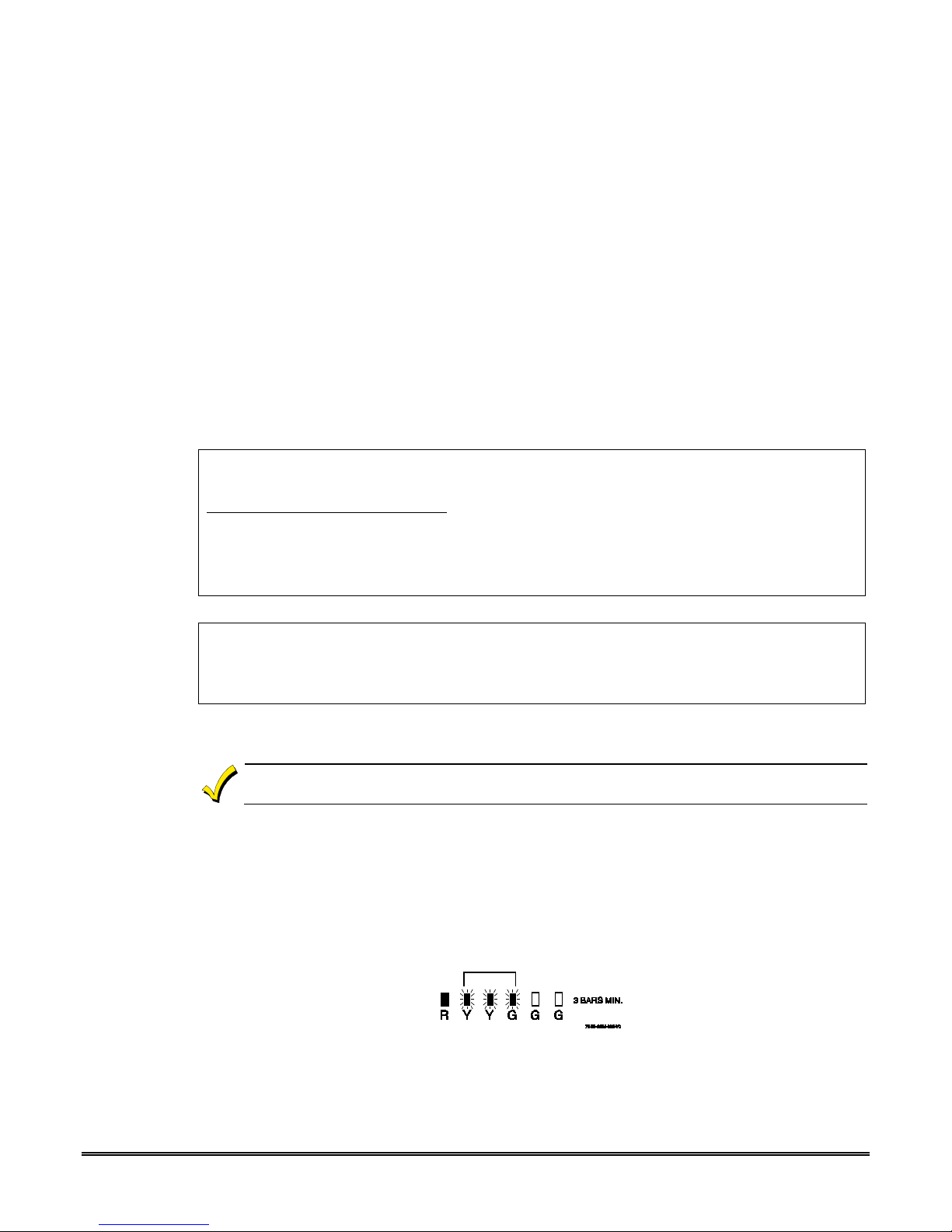
3. Choose the installation site with the best signal strength by observing the signal
strength (RSSI) bar graph (refer to Appendix A for information about signal strength and
status indications). Signal strength should be within 3-5 bars. The best signal strength
is usually found at the highest point in the building, near a window.
4. Mark the location for the communicator.
2-1

IGSMHS4G Installation and Setup Guide
UL
Mounting the Communicator
The cover must be secured with the supplied screw.
1. Locate the case back over selected mounting position such that the opening in the case
back is aligned with the wire
2. Pass the wire
able knockouts located on the back cover.
3. Secure the case back to the mounting surface using four screws (supplied).
4. When all wiring is completed, attach the case front. Position the top first, then press the
bottom section until it snaps in place. Secure bottom using the supplied cover screw.
(This is required for UL installations.)
/ cable through the opening in the case back, or route through the remov-
/ cable opening on the mounting surface.
2-2
Typical Mounting
Wiring the Communicator
UL
Section 2: Mounting and Wiring
UL
• Installation must be in accordance with; the National Electrical Code, UL681 Installation and
Classification for Burglary and Hold-Up Alarm Systems, and UL827 for Central-Station Alarm
Services.
• The communicator must be connected to a UL Listed dry contact or voltage trigger outputs of a UL
Listed compatible control panel.
• The UL Listed control panel and the communicator must be within 3 feet of each other and contained
in the same room. Use a minimum of 22AWG wire. All interconnecting wiring must be installed in
rigid or EMT (where exposed on interior walls) or in flexible metal tubing if run in the walls or ceiling.
• A UL Listed control panel must monitor the radio fault output of the communicator. Premises
openings and closings should be sent via the UL Listed control panel.
• Only ECP mode and Zone Trigger mode has been evaluated by UL.
• 4204 Mode, and Two-4204 Mode has not been evaluated.
Wiring for ECP, 4204 and Two-4204 Modes
Most Honeywell control panels support ECP data communication. Check the Installation
and Setup Guide for the control panel you are using to see if it supports ECP communication.
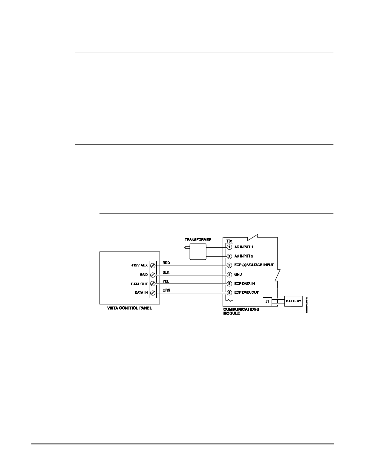
Connect the communicator to a compatible Honeywell VISTA control panel's ECP terminals,
in parallel with keypads and other peripheral devices such as RF receiver, VIP module, etc.
To wire the communicator for ECP or 4204 modes, see the figure below and make the
following connections:
Use minimum 22AWG wire, with maximum length of 450 feet.
Wiring a VISTA for ECP Mode or 4204 Modes
2-3
IGSMHS4G Installation and Setup Guide
Wiring for Zone Trigger Mode
To trip a zone using a positive trigger
6V or greater = positive trigger. (Levels above +14V may cause damage to the unit.)
4V or less = restore.
To trip a zone using a negative trigger
4V or less = negative trigger.
6V or greater = restore. (Levels above +14V may cause damage to the unit.)
NOTE: Remember to program the communicator zone for the desired trigger type.
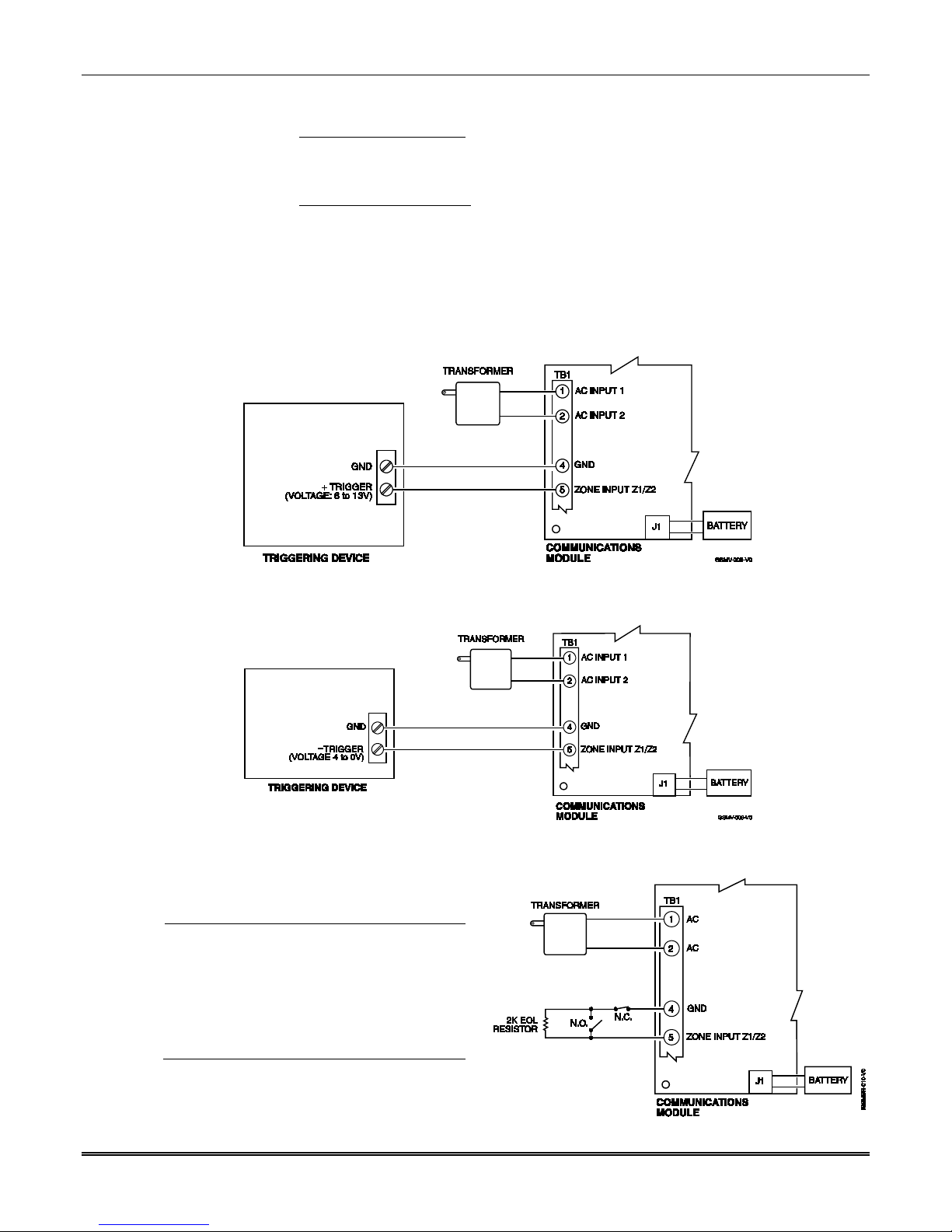
Connect a wire from the triggering source (bell output, voltage trigger, etc.) of the control
panel to the zone input of the communicator, and connect a common ground between the
communicator and control panel. Examples of zone connections follow:
, the voltage level must be:
, the voltage level must be:
Wiring Zone 1 Input for a Positive (+) Trigger
Wiring Zone 1 Input for a Ground (-V) Trigger
UL
• Zones should use EOL resistors, and be
programmed as V+ Inverted or V– Inverted
operation such that a cut line results in an
alarm.
• EOL resistors must be UL Listed.
• Do not use zones 1 and 2 for UL
installations.
Wiring Zone 1 Input for EOL Supervised N.O. /
2-4
N.C. Triggers
Wiring the Fault Relay
Use a Listed cable
DSL router suited for the application.
You may wire and program the communicator's fault output trigger for fail-safe mode (see
the prompt "FLT REL ON Y/N").
To sense a communicator fault at the control panel, see the figure below and make the
following connections. Include the proper EOL resistor required by the control panel.
Section 2: Mounting and Wiring
UL
For Commercial Burglary, a 24 hour zone (supervisory) must be assigned on the control panel,
with the communicator's fault relay wired to that zone.
Wiring the Fault Relay to a Control Panel Zone for Normally Closed Fault
Internet Connection
• For UL installations, the Ethernet connection between the communicator and the router can-
UL
not exceed 12 feet with both the communicator and the router located within the same room.
•
/
Connect one end of the Ethernet cable to the communicator’s RJ45 Ethernet connector and
the other end to the cable
/ DSL router as shown in the figure below.
Internet Connection
2-5

IGSMHS4G Installation and Setup Guide
UL
NOTE:
Standard
Alternate
Installation
Power Connections and Options
Powering the Communicator
For a standard installation, primary power is provided by the AC plug-in transformer. For
ECP communication, you must also connect the +12VDC AUX voltage output of the control
panel (9.6V-13.8V typical) see below.
In all installations, TB1-4 GND must be connected to ground (GND) on the control panel.
Installation
The alternate installation shown below has not been evaluated by UL.
Powering the Communicator
When calculating the total load on the auxiliary power output of the control panel, budget 10mA
for the communicator when using ECP mode.
Backup Battery Connection
The included battery (K14139) is used for backup in the event of power loss to the
communicator. It does not provide power to the control panel.
• The battery can provide over 24 hours of system life in the event of a power failure.
• A programmable power loss message can alert the AlarmNet Control Center when system
power is lost (power loss messages are reported within 1-3 hours of actual loss).
• The communicator transmits a low-battery message (programmable) when the battery
reaches 5.7V ±5%, indicating subsequent messages may not be transmitted.
• The system shuts down when the battery falls below 5.1V, and radio transmissions are no
longer possible.
2-6

• If system power is restored before the communicator shuts down, a power restore message
is sent within 1-3 hours after power is restored, and the battery is recharged using the
communicator’s built-in battery charger. If system power is restored after the communicator has shut down, a power-on reset condition exists, the communicator initializes
itself and the battery will recharge.
NOTE: Do not plug the battery in until after you have powered-up the communicator.
Refer to the Summary of Connections diagram, and install the battery as follows:
1. Place the battery inside the case back.
2. Snap the right side of the battery clip onto the inside of the case back and secure the left
side with the screw provided.
Initial Power-Up Sequence
Before connecting power, check that the following have been completed:
• If using ECP, 4204 or 2-4204 Mode, terminal block TB1 V+ and GND terminals are
connected to the control panel’s auxiliary power output: 12VDC nominal.
• Plug in the transformer.
• Connect the red and black battery cables to the battery terminals. Connect battery cable
to connector J1.
• Power up the control panel.
• Initially, all communicator programming options are set to the factory default settings.
Section 2: Mounting and Wiring
2-7

IGSMHS4G Installation and Setup Guide
2-8

SECTION 3
UL
nnnn (Required for the communicator to report.)
00 (Dialer and LRR reports go out at the same time.)
1 (Communicator, as first reporting.)
111111 (All events will be reported to the primary Central
000000 (If Central Station #2 is not used.)
Zone programming – set Zone 803 for Type 05.
Programming the Communicator
• • • • • • • • • • • • • • • • • • • • • • • • • • • • • • • • • • • • • • • • • • • • • • • • •
General Information
The communicator is designed to deliver alarms via the Internet to an AlarmNet central
station or via the AlarmNet-G network, using GSM (Global System for Mobile) technology
when the Internet is not available.
The communicator uses 256 bit AES (Rijndael) encryption which is required for certain
government installations.
The communicator requires an AlarmNet–I account. For new installations, please obtain the
account information from the central station prior to programming this communicator. For
replacement installations, the AlarmNet-i account is created automatically when the commu-
You can program a communicator by one of the following methods:
nicator is registered.
• Through the AlarmNet Direct website
• Through use of a 7720P Programming Tool
• Through a programming mode in the control panel, on panels that support this
option
Only ECP and Zone Trigger modes have been evaluated by UL.
Programming the Control Panel to work with the IGSMHS4G
For Commercial control panels, there are certain programming field settings that must be
adhered to for using the communicator. (For programming information, please refer to the
appropriate control panel guides.) Ensure the following programming fields are set:
COMMERCIAL Control Panels
UL: For compatible control panels, refer to the “Compatibility” topic in section 1.
Programming Field Setting
32 Primary Subscriber's Acct No.
56 Dynamic Signaling Delay
57 Dynamic Signaling Priority
58 Comm Central Station #1
Category Enable
59 Comm Central Station #2
Category Enable
#93 Menu Mode
Station.)
111111 (If Central Station #2 is used.)
Device programming – set Address 03 for Type 06 (LRR).
3-1
IGSMHS4G Installation and Setup Guide
KEY
NORMAL KEY FUNCTION
SHIFT KEY FUNCTION
BS / ESC
[BS]: Press to delete entry
[ESC]: Press to quit program mode; also can reset
programming defaults*
/ ↑
[↓]: Scroll down programming
[↑]: Scroll up programming
N / Y
[N]: Press for "NO" answer
[Y]: Press SHIFT-Y for "YES" answer
SHIFT
Press before pressing a SHIFT key function. Will light SHIFT LED. LED goes out once a key
is pressed. Press again for each SHIFT function desired.
1 / A
[1]: For entering the number 1
[A]: For entering letter A
2 / B
[2]: For entering the number 2
[B]: For entering letter B
3 / C
[3]: For entering the number 3
[C]: For entering letter C
4 / D
[4]: For entering the number 4
[D]: For entering letter D
Using the AlarmNet Direct Website
To program the communicator via the website (if you are already signed up for this service),
go to: https://services.alarmnet.com/AlarmNetDirect/userlogin.aspx
If you are not signed up for this service, click on “Dealer Sign-Up.
Log in and follow the on-screen prompts.
Please have the following information available when programming the communicator:
1. Primary City ID (two-digit number)
2. Primary Central Station ID (two-digit hexadecimal number)
3. Primary Subscriber ID (four-digit number)
4. MAC ID and MAC CRC number (located on the box and inside the communicator)
After programming is complete, you must transfer the data to the communicator and the
communicator must be registered. Refer to Section 4: Registration, for further instructions.
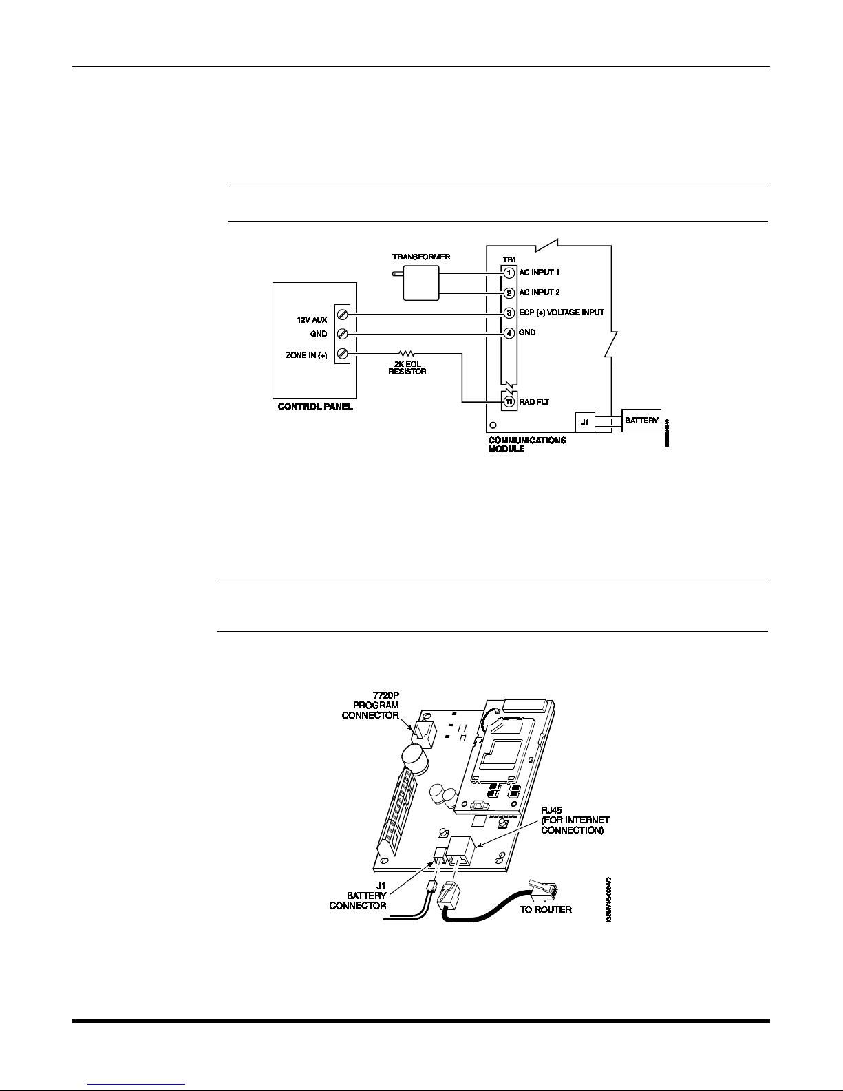
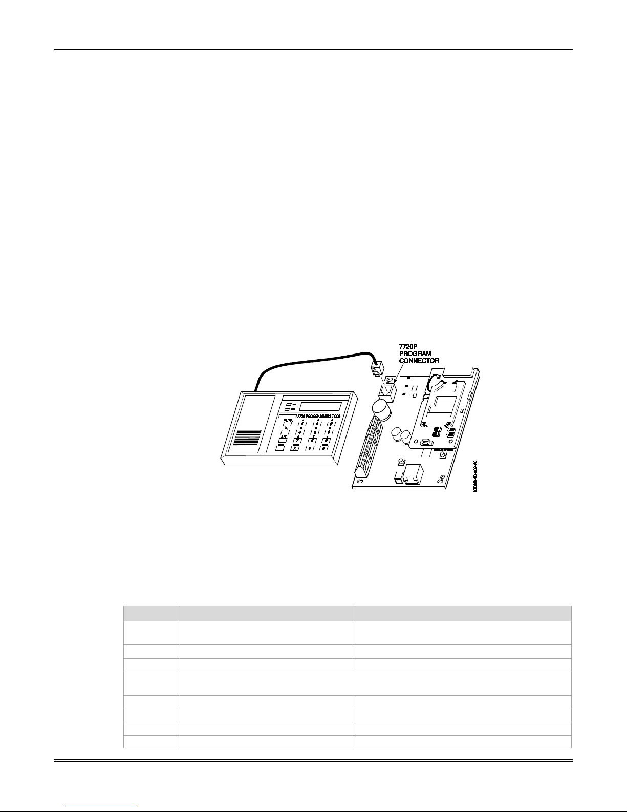
Using a 7720P Programming Tool
Connect the 7720P Programming Tool as shown below. The communicator powers the 7720P
Programming Tool via the programming jack, and automatically senses the presence of the
7720P when it is plugged in.
3-2
7720P Programming Tool Connection
Each key of the 7720P has two possible functions: a normal function and a Shift function.
To perform a normal key function, simply press the desired key.
To perform a Shift function, press the [shift] key, and then press the appropriate key.
The prompts in this document reflect use of the 7720P Programming Tool. The table below
lists each normal and shift key function.
Table 3-1. 7720P Normal and Shift Key (shift LED lit) Functions
↓
 Loading...