


Installation and Operation Guide
IFP-2100/ECS
RFP-2100
Analog/Addressable Fire System
Emergency Communication System
Document: LS10143-001SK-E Rev: B
ECN: 17-0364

Fire Alarm & Emergency Communication System Limitations
While a life safety system may lower insurance rates, it is not a substitute for life and property
insurance!
An automatic fire alarm system—typically made up of smoke
detectors, heat detectors, manual pull stations, audible warning
devices, and a fire alarm control panel (FACP) with remote notification capability—can provide early warning of a developing
fire. Such a system, howe ver, does not assu re protection
against property damage or loss of life resulting from a f ire.
An emergency communication system—typically made up of
an automatic fire alarm system (as described above) and a life
safety communication system that may include an autonomous
control unit (ACU), loca l operating console (LOC), voi ce communication, and other var i ous inter-operable communication
methods—can broadcast a mass notification message. Such a
system, however, does not assure pro te ct io n against property
damage or loss of life resulting from a fire or life safety event.
The Manufacturer recommends that smoke and/or heat
detectors be located throughout a protected premises following
the recommendations of the cur r ent edi t i on of the Na t ional Fi re
Protection Association Standard 72 (NFPA 72), manufacturer's
recommendations , State and local codes, and the
recommendations contained in the Guide for Proper Us e of
System Smoke Detectors, which is made available at no charge
to all installing dealers. This docu ment can be found at http://
www.systemsensor.com/appguides/. A study by the Federal
Emergency Manage m ent Agency (an agency of th e U nit ed
States government) indicated that smoke detectors may not go
off in as many as 35% of all fires. Wh ile fire alarm systems are
designed to provide earl y w ar ni ng against fire, they do not
guarantee warning or protection against fire. A fire alarm
system may not provide timely or adequate warni ng, or simply
may not funct i on, for a vari ety of reasons:
Smoke detectors may not se nse fire where smoke cannot
reach the detectors such as in chimneys, in or behind walls, on
roofs, or on the other side of clo sed doors. Smoke detectors
also may not sense a fire on another level or floor of a building.
A second-floor detector, for example, may not sense a first-floor
or basement fire.
Particles of combustion or “smoke” from a developing fire
may not reach the sensing chambers of smoke detectors
because:
• Barriers such as closed or partially closed doors, walls,
chimneys, even wet or humid areas may inhibit particle or
smoke flow.
• Smoke particles ma y become “cold,” stratify, and not reach
the ceiling or upper walls where detectors are locate d.
• Smoke particles ma y be blown away from detec to rs by air
outlets, such as air conditioning vents.
• Smoke particles may be drawn into air returns before reaching the detector.
The amount of “smoke” pres ent may be insufficient t o alarm
smoke detectors. Smoke detectors are design ed t o al ar m at
various l evels of smoke de nsity. If such de nsity level s are not
created by a developing fire at the location of detectors, the
detectors will not go into ala rm.
Smoke detectors, even when working properly, have sensing
limitations. Detector s th at have photoelectronic se nsing chambers tend to detect smolder i ng f i re s bet t er th an f lam i ng f ires,
which have little visible smoke. Detectors that have ionizingtype sensing chamber s te nd to detect fast-flaming fire s better
than smoldering fires. Because fires develop in different ways
and are often unpredictable in their growth, neither type of
detector is necessar ily be st and a given type of detector ma y
not provide adequate war ni ng of a fire.
Smoke detectors cannot be expected to provide adequate
warning of fire s cau sed by ar son, chi ldren play in g with matche s
(especially in bedrooms), smoking in bed, and vio le nt exp lo -
sions (caused by escaping gas, improper storage of flammable
materials, etc.) .
Heat detectors do not sense particles of combustion and alarm
only when heat on their s ensors increases at a predetermined
rate or reaches a predet er m i ned le vel . Ra te-of-rise heat detectors may be subject to re duc ed sensitivity over time. For th is
reason, the rate-of- rise featur e of each detector should be
tested at least once per y ear by a qualified fire protection specialist. Heat detector s ar e des i gned to protect property, not life.
IMPORTANT! Smoke detectors must be installed in the same
room as the control panel and in rooms used by the sy st em f or
the connection of alarm transmission wiring, communicati ons,
signaling, and/or power. If detectors are not so located, a developing fire may damage the alarm system, compromising its
ability to report a fire.
Audible warning devices such as bells, horns, strobes ,
speakers and displays may not alert people if these devices
are located on the other side of closed or partly open doors or
are located on another floo r of a building. Any warning device
may fail to alert people with a disability or those who have
recently consumed drugs, alcohol, or medication. Please note
that:
• An emergency communication system may take priority over
a fire alarm system in the event of a life safety emerg enc y.
• Voice messaging systems must be designed to meet intelligibility requirements as defined by NFPA, local codes, and
Authorities Having Jurisdiction (AHJ).
• Language and inst r u cti onal requirements must be cl e arly
disseminated on any lo cal displays.
• Strobes can, under certain circumstances, cause seizures in
people with conditions such as epilepsy.
• Studies have sho w n t hat certain people, even when they
hear a fire alarm signal, do not re spond to or comprehend
the meaning of the sign al . Audible devices, such as horns
and bells, can have different tonal patterns and frequencies.
It is the property owner's responsibility to conduct fire drills
and other training exer cises to make people aware of fire
alarm signals and instr uc t them on the proper reaction to
alarm signals.
• In rare instances, the sounding of a warning device can
cause temporary or perman ent hearing loss.
A life safety system will not operate without any electrical
power. If AC power fails, the system w i ll op era t e from st andby
batteries only for a speci fied time and only if the batteries have
been properly maintained and replaced regular ly.
Equipment used in the system may not be technically compatible wi th the control panel. It is essential to use only equipment listed for service w ith your control panel.
Telephone lines needed t o t r ans mi t al ar m si gn al s f ro m a p re m ises to a central monitoring station may be out of service or
temporarily disabled . For a dde d protection against telepho ne
line failure, backup radio transmission syst em s ar e recommended.
The most common cause of life safety system malfunction is
inadeq u ate maintenance. To keep the en tire life safety sys tem
in excellent working order, ongoing maintenance is required per
the manufacturer's recommendations, and UL and NFPA standards. At a minimum, the requirements of NFPA 72 shall be followed. Environments with large amounts of dust, dirt, or high air
velocity require more frequent maintenance. A maintenance
agreement should be arranged through t he local manufacturer's representat ive. M ai nt enance should be sched uled
monthly or as required by National and/or local fire codes and
should be performed by authorized professional l ife safety system installers only. Adequate written records of all inspections
2

Installation Precautions
Adherence to the following will aid in problem-free installation with long-term reliability:
WARNING - Several different sources of power can be
connected to the fire alar m cont rol panel. Disconnect all
sources of power be fore servi cing . Contr ol uni t and associ ated
equipment may be damaged by removing and/ or in serting
cards, modules, or in te rc on necting cables while the uni t is
energized. Do not attem pt to install, service, or ope ra te th is
unit until manuals are read and understood.
CAUTION - System Re- acceptance Test after Software
Changes: To ensure proper system operation, this product
must be tested in acc or dance with NFPA 72 after any programming operatio n or change in site-specific softw are. Reacceptance testin g is req u ir ed af t er any change, addition or
deletion of system co mponents, or after any modification,
repair or adjustmen t to sy st em hardware or wiring. All components, circuits, syst em operations, or software f unc tions
known to be affected by a change must be 100% tested. In
addition, to ensure that ot her operations are not inadver tent ly
affected, at least 10% of initiat i ng devi ces that are not directly
affected by the change, up to a maximum of 50 devices, must
also be tested and proper system operation verified.
This system meets NFPA requirements for operation at 0-49º
C/32-120º F and at a relative humidity. However, the useful
life of the system's standby batteries and the electronic components may be adversely affected by extreme temperature
ranges and humidity. Therefore, it is recommended th at th is
system and its peripherals be installed in an environment with
a normal room temperature of 15-27º C/60-80º F.
Verify that wire sizes are adequate for all initiating and indicating device loops. Most devices cannot tolerate more than a
10% I.R. drop from th e specified device voltage .
Like all solid state electronic devices, this system may
operate erratically or can be damaged when subjected to lightning induced transients. Although no syste m is com pletely
immune from lightning tr ans i ent s and interference, proper
grounding will reduce susceptibility. Overhead or outside
aerial wiring is not recommended, due to an increased susceptibility to nearby lig ht ni ng strikes. Consult with the Technical Services Department if any problems are anticip at ed or
encountered.
Disconnect AC power and batteries prior to removing or
inserting circuit boards . Fa ilur e t o do so can damage circuits.
Remove all electronic assemblies prior to any drilling, filing,
reaming, or punching of th e enclosure. When possib le , ma ke
all cable entries from the sides or rear. Before making modifications, verify that they will not interfere with battery, transformer, or printed circuit board location.
Do not tighten screw terminals more than 9 in -lbs . Overtightening may damag e t hr eads, resulting in reduced term i nal
contact pressure and di fficu lty wit h screw terminal removal .
This system contains st at ic- sensitive components .
Always ground yourself with a proper wrist strap before han-
dling any circuits so that static charges are removed from the
body. Use static suppressive packaging to protect electronic
assemblies remov ed from the unit.
Follow the instructio ns in th e i nst allation, operating, and
programming manuals. These instructions must be followed to
avoid damage to the control panel and associated equipment.
FACP operation and reliability depend upon proper installation.
Precau-D1-9-2005
3

Documentation Feedback
Your feedback helps us keep our documentation up-to-date and accurate. If you have a question or encounter a
problem not covered in this manual, contact Honeywell Silent Knight Technical Support at 800-446-6444.
Please give the following information:
• Product name and version number (if applicable)
• Printed manual
• T opic T itle
• Page number (for printed manual)
• Brief description of content you think should be improved or corrected
• Your suggestion for how to correct/improve documentation
To order parts, contact Honeywell Silent Knight inside sales at 800-328-0103.
eVance®, Farenhyt™ are trademarks; and Honeywell®, Silent Knight® and SWIFT® are registered trademarks of Honeywell Internati onal Inc.
Microsoft® and Windows® are registered trade ma rks of t he M icro soft C o rpo ra tion. Chrome™ and Google™ are trademarks of Google Inc. Firefox®
is a registered trademark of The Mozilla Foundation.
©2017 by Honeywell Internati onal Inc . All rights reserved. Una utho ri zed use of this docu me nt is stric tly prohibit ed .
4

Contents
Section 1
Introduction ..................................................................................................................................................1
1.1 Overview of Basic System ...........................................................................................................1
1.1.1 Hardware Features ...............................................................................................................1
1.1.2 Network System Hardware Features ....................................................................................2
1.1.3 Software Features ................. ...... ....... ...... ............................................. ................................2
1.1.4 IFP-2100ECS Features .........................................................................................................2
1.1.5 Terms Used in this Manual ...................................................................................................3
1.2 Compatible Products ...................................................................................................................3
Section 2
Agency Listings, Approvals, and Requirements .......................................1
2.1 Federal Communications Commission (FCC) .............................................................................1
2.2 Underwriters Laboratories (UL) ...................................................................................................2
2.2.1 Requirements for All Installations .........................................................................................2
2.2.2 Requirements for Central Station Fire Alarm Systems .........................................................3
2.2.3 Requirements for Local Protected Fire Alarm Systems ........................................................3
2.2.4 Requirements for Remote Station Protected Fire Alarm Systems ........................................3
2.2.5 Requirements for the Installation of Carbon Monoxide (CO) Detection and Warning
Equipment, NFPA 720 ..........................................................................................................3
2.2.6 NFPA Requirements .............................................................................................................3
Section 3
Before You Begin Installation ..............................................................................................1
3.1 Inventory ............................... .................... ................... ................... .................... .........................1
3.2 Environmental Specifications ......................................................................................................1
3.3 Software Downloads ............................................. ...... ...... ....... ...... .............................................1
3.4 Electrical Specifications ...............................................................................................................2
3.5 Wiring Specifications ...................................................................................................................4
3.6 Board Assembly Diagram ............................................................................................................6
3.7 Calculating Current Draw and Standby Battery ...........................................................................7
3.7.1 Current Draw Worksheet Requirements ...............................................................................7
3.7.2 Current Draw Worksheet for IDP SLC Devices ....................................................................7
3.7.3 Current Draw Worksheet for SK SLC Devices ....................................................................11
3.7.4 Current Draw Worksheet for SD SLC Devices ...................................................................15
3.7.5 Maximum Battery Standby Load .........................................................................................19
Section 4
Control Panel Installation ..........................................................................................................1
4.1 Mounting the Control Panel Cabinet ...........................................................................................1
1

Model IFP-2100/ECS Installation Manual
4.1.1 Preventing Water Damage ....................................................................................................1
4.1.2 Removing the IFP-2100/ECS Assembly from the Housing ...................................................2
4.1.3 Ethernet Connection .............................................................................................................2
4.2 AC Power Connection ....................................................... ....... ...... ....... ...... ................................2
4.3 Battery Power ..............................................................................................................................3
4.3.1 Battery Accessory Cabinets ..................................................................................................3
4.3.1.1 Installing the RBB or AB-55 Accessory Cabinet and Batteries ...................................3
4.4 SBUS Wiring ...............................................................................................................................5
4.4.1 Calculating Wiring Distance for SBUS Modules ...................................................................5
4.4.2 Wiring Configurations ............................................................................................................8
4.5 RA-2000 Remote Annunciator Installation ..................................................................................9
4.5.1 Mounting the RA-2000 ....................................................... ...... ....... ...... ....... .........................9
4.5.1.1 Flush Mounting ............................................................................................................9
4.5.1.2 Surface Mounting ......................................................................................................11
4.5.2 RA-2000 Connection to the Panel .....................................................................................12
4.5.3 Temporary Programming Display ............ ....... ...... ...... ....... ...... ....... ...... ....... ...... ....... ...... ....12
4.6 RA-1000 Remote Annunciator Installation ................................................................................13
4.6.1 Mounting the RA-1000 ........................................................................................................13
4.6.1.1 Flush Mounting ..........................................................................................................15
4.6.1.2 Surface Mounting ......................................................................................................16
4.6.2 Model RA-1000 Connection to the Panel . ....... ...... ...... ....... ...... ....... ...... ..............................16
4.7 RA-100 Remote Annunciator Installation ..................................................................................17
4.7.1 Mounting the RA-100 ..........................................................................................................17
4.7.1.1 Flush Mounting ..........................................................................................................17
4.7.1.2 Surface Mounting ......................................................................................................19
4.7.2 Model RA-100 Connection to the Panel ..............................................................................20
4.8 5815XL Installation ....................................................................................................................21
4.8.1 5815XL Connection to the Panel ........................................................................................21
4.9 6815 Installation ........................................................................................................................22
4.9.1 6815 Connection to the Panel .............................................................................................23
4.10 5824 Serial/Parallel Interface Module Installation .....................................................................24
4.10.1 Selecting 5824 Options .......................... ....... ...... ...... ....... ...... ....... ...... ....... ...... ....... ..........24
4.11 5880 LED I/O Module ................................................................................................................26
4.11.1 5880 Board Layout ............................................................................................................26
4.11.2 FACP Connection ................ ...... ....... ............................................. ....................................26
4.11.3 LED Wiring ............................................. ............................................. ..............................27
4.11.4 Dry Contact Wiring ............................................................................................................28
4.12 5865-3 / 5865-4 LED Annunciator Installation ...........................................................................29
4.12.1 FACP Connection ................ ...... ....... ............................................. ....................................29
4.12.2 5865 Mounting ........ ...... ....... ...... ....... ...... ............................................. ..............................30
4.13 Configuring SBUS Modules .......................................................................................................31
4.13.1 Assigning SBUS Module IDs .............................................................................................31
4.13.2 SBUS Bandwidth Considerations ......................................................................................31
4.14 Telephone Connection ..............................................................................................................32
4.15 Flexputs
™
I/O Circuits ...............................................................................................................32
4.15.1 Conventional Notification Appliance ..................................................................................32
4.15.1.1 Class B Notification Wiring .......................................................................................32
4.15.1.2 Class A Notification Wiring ......................................................................................33
4.15.2 Conventional Input Switch Circuits ....................................................................................34
4.15.2.1 Class B Inputs ..........................................................................................................34
4.15.2.2 Class A Inputs ..........................................................................................................35
4.15.3 Installing 2-Wire Smoke Detectors ....................................................................................35
4.15.3.1 Installing 2-Wire Class B Smoke Detectors .............................................................36
4.15.3.2 Installing 2-Wire Class A Smoke Detectors ............................................................36
2

4.15.4 Installing 4-Wire Smoke Detectors ....................................................................................36
4.15.4.1 Installing a Class B 4-Wire Smoke Detectors ..........................................................37
4.15.4.2 Installing 4-Wire Class A Smoke Detectors .............................................................37
4.15.5 Auxiliary Power Installation ........................................ ........................................................38
4.15.5.1 Door Holder Power ...................................................................................................39
4.15.5.2 Constant Power ........................................................................................................39
4.15.5.3 Resettable Power .....................................................................................................39
4.15.5.4 Sounder Sync Power ...............................................................................................39
4.16 On-Board Relays (Conventional) ..............................................................................................39
4.16.1 Trouble Relay ...................... ...... ....... ...... ....... ...... ...... ....... ...... ...........................................39
4.16.2 Programmable Relays ................................... ...... ...... ....... ...... ....... ...... ....... .......................39
4.17 Remote Station Applications ....................................... ...... ....... ...... ....... ...... ....... ...... ....... ..........40
4.17.1 Keltron Model 3158 Installatio n ................................. ....... ...... ....... ...... ....... ...... ....... ...... ....40
4.17.2 City Box Connection Using the 5220 Module ....................................................................40
4.17.3 Using the Addressable Relay Module for City Box Connection .........................................41
4.17.4 NFPA 72 Polarity Reversal ........ ....... ...... ....... ...... ...... ....... ...... ....... ...... ....... .......................41
4.17.4.1 Using the 5220 Module ............................................................................................42
4.17.4.2 Using the 7644-L8 Module .......................................................................................43
4.17.5 Transmitter Activated by Dry Contacts ..............................................................................44
Section 5
Networking ....................................................................................................................................................1
5.1 Network System Hardware Features ..........................................................................................1
5.1.1 Networked Sites ....................................................................................................................1
5.1.2 Wiring Options to Connect Networked Panels ......................................................................1
5.2 Model RFP-2100 .........................................................................................................................1
5.3 Network Wiring ............................................................................................................................1
5.4 SK-NIC Wiring Options ................................................................................................................3
5.4.1 Fiber Loop Modules ..............................................................................................................3
5.4.1.1 Accessory Mounting Kits .............................................................................................4
5.4.2 SK-NIC Installation ................................................................................................................4
5.4.2.1 Unshielded Twisted Pair Wiring between Multiple Panels ..........................................6
5.4.2.2 Fiber Optic Multi-Mode Wiring between Multiple Panels .............................................7
5.4.2.3 Fiber Optic and Twisted Pair Wiring between Multiple Panels ....................................9
5.5 Setting the Network ID for each Panel ......................................................................................10
Section 6
Network Management .....................................................................................................................1
6.1 Network Diagnostics ....................................................................................................................1
6.1.1 Ping Panel .............................................................................................................................1
6.1.2 Data Network Status ............................................................................................................1
6.1.3 Voice Network Status ............................................................................................................1
6.2 Network Programming .................................................................................................................1
6.2.1 Learn Network .......................................................................................................................1
6.2.2 Edit Network Names .............................................................................................................2
6.2.3 Edit Panel ID .........................................................................................................................2
6.2.4 Computer Access ........... ....... ...... ....... ...... ....... ...... ...... .............................................. ............2
6.2.5 Access Codes .......................................................................................................................3
6.2.5.1 Edit Name ...................................................................................................................4
3

Model IFP-2100/ECS Installation Manual
6.2.5.2 Edit Access Code ........................................................................................................4
6.2.5.3 Panel Functions ..........................................................................................................4
6.2.6 Communicator Options .........................................................................................................5
6.2.6.1 Communicator Assignments .......................................................................................5
6.2.6.2 Communicator Miscellaneous .....................................................................................5
6.2.6.3 Receiver Configuration ................................................................................................5
6.2.6.4 Communicator Reporting Table ..................................................................................6
6.3 Voice Options ..............................................................................................................................6
6.3.1 Edit Timers ............................................................................................................................6
6.3.1.1 Control Lockout ...........................................................................................................6
6.3.1.2 Auto Reset ECS MIC Triggered Event ........................................................................7
6.3.2 Edit Voice Commands ..........................................................................................................7
6.4 Sync Network Options .................................................................................................................8
6.5 Network Management Quick Reference .....................................................................................9
Section 7
IDP, SK, SD and SWIFT™ SLC Device Installation ................................1
7.1 List of IDP SLC Devices ..............................................................................................................1
7.2 List of SK SLC Devices ...............................................................................................................2
7.3 List of SD SLC Devices ...............................................................................................................3
7.4 List of SWIFT Wireless SLC Devices ..........................................................................................4
7.5 Maximum Number of SLC Devices .............................................................................................4
7.6 Wiring Requirements for SLC Devices ........................................................................................4
7.6.1 Wire Sizing on 5815XL for SD Devices ................................................................................5
7.6.2 Wire Sizing for 6815 ..............................................................................................................5
7.6.3 Wiring Requirements for IDP or SK Modules .......................................................................5
7.6.4 Wiring 5815XL or 6815 in Style 6 & 7 (Class A) Configuration .............................................6
7.7 Addressing IDP or SK SLC Devices ............................................................................................7
7.8 Wiring SD Detectors ....................................................................................................................8
7.9 Addressing SD Devices ............... ...... ............................................. .............................................8
7.9.1 SLC Devices with DIP Switches .........................................................................................10
7.10 Wiring the WIDP-WGI or SK-WGI .............................................................................................11
7.10.1 Power Connections for the Gateway .................................................................................11
Section 8
Programming Overview ...............................................................................................................1
8.1 JumpStart® AutoProgramming ...................................................................................................1
8.1.1 Input Points ...........................................................................................................................1
8.1.2 Output Points ........................................................................................................................1
8.1.3 Running JumpStart® AutoProgramming ..............................................................................2
8.2 Mapping Overview .......................................................................................................................4
8.2.1 Input Point Mapping ..............................................................................................................5
8.2.2 Output Circuit Mapping .........................................................................................................6
8.2.3 Event Mapping .....................................................................................................................7
8.2.4 Mapping LED Points ...........................................................................................................11
8.2.5 Mapping LED Points for a Networked System ....................................................................12
8.3 Programming Using the HFSS Honeywell Fire Software Suite .................................................12
8.4 Programming Using an Annunciator .........................................................................................12
8.4.1 Entering / Exiting Panel Programming ................................................................................12
4

8.4.1.1 Moving through the Menus ........................................................................................13
8.4.1.2 Selecting Options and Entering Data ........................................................................13
8.5 Programming Menu Quick Reference .......................................................................................14
Section 9
Programming .............................................................................................................................................1
9.1 UL 864 / UL 2572 Programming Requirements ..........................................................................1
9.2 Modules .......................... ............................................. ................................................................2
9.2.1 Edit Modules .........................................................................................................................2
9.2.1.1 Editing Module ID ........................................................................................................2
9.2.1.2 Naming Modules .........................................................................................................2
9.2.1.3 Changing Module Options ...........................................................................................3
9.2.2 Adding a Module ...................................................................................................................3
9.2.3 Deleting a Module .................................................................................................................3
9.2.4 View Module List ...................................................................................................................3
9.3 Zone ............................................................................................................................................4
9.3.1 Edit Zone ...............................................................................................................................4
9.3.1.1 Edit Zone Name ..........................................................................................................4
9.3.1.2 Edit Zone Properties ...................................................................................................4
9.3.1.3 Zone Accessory Options .............................................................................................6
9.3.2 View Zone Points ..................................................................................................................7
9.4 Group ..........................................................................................................................................7
9.4.1 Edit Group .............................................................................................................................7
9.4.1.1 Edit Group Name ........................................................................................................7
9.4.1.2 Edit Group Properties ..................................................................................................7
9.4.2 View Group Points ................................................................................................................9
9.4.3 Edit OPG Template ...............................................................................................................9
9.5 Point ............................................................................................................................................9
9.5.1 Point Programming For 5815XL Module ...............................................................................9
9.5.2 Point Programming For 6815 Module .................................................................................12
9.5.3 Point Programming For Internal or External Power Module (RPS-1000) ...........................15
9.5.4 Point Programming For 5880/5865 Modules ......................................................................17
9.5.5 Point Programming for 5496 ...............................................................................................17
9.5.6 Point Programming for ECS-AMP .......................................................................................18
9.5.7 Point Programming for ECS-VCM, ECS-NVCM or ECS-RVM ...........................................19
9.6 System Options .............................................. ....... ...... ............................................. .................21
9.6.1 Communication Options ......................................................................................................21
9.6.1.1 Auto Test Time ..........................................................................................................21
9.6.1.2 Phone Lines ..............................................................................................................22
9.6.1.3 Edit Ethernet .............................................................................................................24
9.6.1.4 AlarmNet Timers .......................................................................................................24
9.6.1.5 Phone Line Gains ......................................................................................................25
9.6.2 Daytime/Nighttime Sensitivity .............................................................................................25
9.6.3 Holiday Days .......................................................................................................................25
9.6.4 Time Options .......................................................................................................................26
9.6.4.1 Water Flow Delay ......................................................................................................26
9.6.4.2 Alarm Verify ...............................................................................................................26
9.6.4.3 AC Report Delay .......................................................................................................27
9.6.4.4 Change AC Line Frequency ......................................................................................27
9.6.4.5 Clock Format (AM/PM or Military) .............................................................................27
9.6.4.6 Auto-Resound (4 or 24 hours) ...................................................................................27
5

Model IFP-2100/ECS Installation Manual
9.6.5 Miscellaneous Options ........................................................................................................27
9.6.5.1 Strobes Active when Silenced ...................................................................................27
9.6.5.2 Auto Display Events ..................................................................................................28
9.6.6 Daylight Saving Options . ....... ..............................................................................................28
9.6.6.1 Automatic Daylight Saving Adjustment .....................................................................28
9.6.6.2 Daylight Saving Time Start and End .........................................................................28
9.6.7 Edit Banner .........................................................................................................................29
9.6.8 SLC Family .........................................................................................................................29
9.7 JumpStart® AutoProgramming .................................................................................................30
9.8 Restore Defaults ............. ...... ....... ...... ....... ...... ....... ...... ...... ....... ...... ....... ...... ....... .......................30
9.9 Voice Options ............................................................................................................................30
9.9.1 VCM Maintenance ..............................................................................................................30
9.9.2 Voice Settings .....................................................................................................................30
9.9.2.1 Enable Dual Channel System ...................................................................................31
Section 10
System Operation ................................................................................................................................1
10.1 Default User and Installer Codes ................................................................................................1
10.2 Annunciator Description ..............................................................................................................1
10.2.1 LCD Display ............ .................................................................................... .........................2
10.2.2 Banner .................................................... ....... ...... ...... ....... ...... ....... ...... ................................2
10.2.2.1 Single Key Acknowledge ............................................................................................2
10.3 Menu System .............................................................................................................................2
10.3.1 Main Menu Overview ........... ...... ....... ...... ....... ...... ...... ....... ...................................................2
10.3.2 Using the Menus ..... ...... ....... ...... ....... ...... ....... ...... ...... ....... ...... ....... ......................................3
10.4 Basic Operation .................... ....... ...... ....... ............................................. ......................................3
10.4.1 Setting Time and Date .........................................................................................................3
10.4.2 Disable / Enable a Point ............ ....... ...... ....... ...... ...... ....... ...... .............................................3
10.4.2.1 Disable / Enable NACs by Template ..........................................................................3
10.4.2.2 Disable / Enable NACs by Group ...............................................................................3
10.4.2.3 Disable / Enable Zone Points .....................................................................................3
10.4.2.4 Disable / Enable Point ................................................................................................4
10.4.2.5 Inhibit Output Group ...................................................................................................4
10.4.3 View Event History ..............................................................................................................4
10.4.3.1 To clear the event history ...........................................................................................4
10.4.4 Conduct a Fire Drill ..............................................................................................................4
10.4.5 Conduct an Indicator Test ................................... ...... ....... ...... ....... ...... ....... ...... ....... ...... ......5
10.4.6 Conduct a Walk Test ...........................................................................................................5
10.4.7 Conduct a Communicator Test ............................................................................................5
10.4.8 Manual AlarmNet Registration .............................................................................................6
10.4.9 Silence Alarms or Troubles .................................................................................................6
10.4.10 Reset Alarms .....................................................................................................................6
10.4.10.1 Reset Communicator ..............................................................................................6
10.4.11 Check Detector Sensitivity Through Point Status .............................................................6
10.4.12 View Status of a Point ......................................................................................................7
10.4.13 View Alarms or Troubles ..................................................................................................8
10.4.14 System Information ...........................................................................................................8
10.5 Event Priority ..............................................................................................................................9
10.5.1 System Control .............................................. ...... ...... ....... ...... ....... ...... ....... ...... ....... ............9
10.5.2 System Override ........................................................ ....... ...................................................9
10.5.3 Event Priority ................ ....... ................................................................................................9
6

10.5.4 Priority Rules ................ ....... ............................................. .................................................10
10.5.5 Other Priority Considerations ............................................................................................10
10.6 Operation Mode Behavior .........................................................................................................11
10.6.1 Multi-Site Annunciator and Multi-Site User Access ...........................................................14
10.7 Releasing Operations ................................................................................................................15
10.7.1 Single Interlock Zone Releasing ........................................................................................16
10.7.2 Double Interlock Zone Releasing ........................ ...... ....... ...... ....... ...... ....... ...... ....... ...... ....17
10.8 Smoke Alarm Verification ..........................................................................................................18
10.9 Function Keys ...........................................................................................................................18
10.9.1 Recording an F-Key Macro ................................................................................................19
10.9.2 Aborting an F-Key Macro Recording Session ...................................................................19
10.9.3 Erasing an F-Key Macro ....................................................................................................19
10.9.4 Using a Recorded F-Key Macro ............. ....... ...... ...... ....... ...... ....... ...... ....... ...... ....... ...... ....19
10.9.5 F-Key Status Event ............................................................................................................19
10.9.6 F-Key Map Inhibit ..............................................................................................................19
Section 11
Emergency Communication System Operation ..........................................1
11.1 Overview .....................................................................................................................................1
11.2 LOC Functionality ........................................................................................................................1
11.2.1 Keys and LEDs ....................................................................................................................1
11.2.1.1 ECS Control Key ........................................................................................................1
11.2.1.2 ECS Control LED .......................................................................................................2
11.2.1.3 ECS Message Keys ...................................................................................................2
11.2.1.4 ECS Message LEDs ..................................................................................................2
11.2.1.5 Select Keys ................................................................................................................2
11.2.1.6 Select Key LEDs ........................................................................................................2
11.2.2 Gaining ECS Control ...........................................................................................................3
11.2.2.1 LOC Priority ................................................................................................................3
11.2.2.2 LOC Lockout ..............................................................................................................3
11.2.2.3 User Profile Access Control .......................................................................................4
11.2.3 Manual ECS ..................................... ...... ....... ...... ...... ....... ...... ....... ...... ....... ...... ....... ............4
11.2.3.1 Switching between Microphone Mode and Message Mode .......................................4
11.2.3.2 Activating Output Groups Dynamically .......................................................................4
11.2.4 Microphone Mode ......... ....... ...... ....... ...... ....... ............................................. .........................5
11.2.5 Message Mode .............................................. ...... ...... ..........................................................5
11.2.6 Custom ECS Event ........................................ ............................................. .........................5
11.2.7 Passing ECS Control ...........................................................................................................5
11.2.8 Exit ECS Control Menu ........................................................................................................6
11.2.9 Relinquish ECS Control .......................................................................................................6
11.2.10 ECS Reset ........................................................................................................................6
11.3 ECS Super User ..........................................................................................................................6
11.4 ECS Point Functionality ...............................................................................................................7
11.4.1 ECS Point Activations ..........................................................................................................7
11.4.2 ECS-VCM, ECS-NVCM & ECS-RVM Points .......................................................................7
11.5 Amplifier Programming ................................................................................................................7
11.5.1 Adding an Amplifier .............................................................................................................7
11.5.2 Editing an Amplifier ..............................................................................................................8
11.6 LOC Programming ......................................................................................................................8
11.6.1 Adding an LOC ....................................................................................................................8
11.6.2 Editing an LOC ....................................................................................................................9
7

Model IFP-2100/ECS Installation Manual
11.6.2.1 LOC Priority ................................................................................................................9
11.6.2.2 LOC Association ........................................................................................................9
11.7 Using the Microphone .................................................................................................................9
11.7.1 Microphone Functionalit y ............................... ...................................... ....... ...... ....... ............9
11.7.2 Custom ECS Event ........................................ ............................................. .........................9
11.7.3 Fire Page ....................................................... ...... ...... ....... ...... ....... ...... ....... ...... .................10
11.7.4 Emergency Page .................................... ....... ...... ...... ....... ...... ....... ...... ....... ...... ....... ..........10
11.7.4.1 Paging ......................................................................................................................10
11.8 Recording Custom Messages ........... ....... ...... ....... ...... ............................................. .................11
11.8.1 Recording Messages 1-15 Using Aux Audio Input ............................................................12
11.8.2 Recording Messages 1-15 Using the Microphone .............................................................14
11.8.3 Erasing User Message ......................................................................................................15
11.8.4 Using HFSS Voice Message Load Software .....................................................................15
11.9 Network Paging .........................................................................................................................16
11.9.0.1 Priority ......................................................................................................................16
11.9.0.2 Configuration ............................................................................................................17
Section 12
Reporting .........................................................................................................................................................1
12.1 Receivers Compatible with the Control Panel .............................................................................1
12.2 SIA - IntelliKnight / IFP-2100/ECS Panels PI Modifier Reporting: .............................................13
12.3 SIA – IFP-2100/ECS Panel Communicator: ..............................................................................14
Section 13
Testing and Troubleshooting ...............................................................................................1
13.1 Troubleshooting ....... .................... ................... ................... .................... ................... ...................1
13.2 Common Problems ......................................................................................................................1
13.3 Periodic Testing and Maintenance ..............................................................................................2
13.4 Event History ...............................................................................................................................3
13.5 Built-in Troubleshooting and Testing Tools .................................................................................3
13.5.1 SLC Device Locator ............. ............................................. ...................................................3
13.5.2 SLC Multiple Device Locator ..... ....... ...... ....... ...... ...... ....... ...... ....... ...... ....... ...... ....... ............3
13.5.3 I/O Point Control ..................................................................................................................4
13.5.4 Earth Fault Resistance ........................................................................................................5
Section 14
Installation Records ..........................................................................................................................1
14.1 Detector and Module Point Record .............................................................................................1
14.2 Conventional Output Point Record ..............................................................................................5
8

Appendix A
Compatible Devices ..........................................................................................................................1
Appendix B
Editing Text Using the Built-In Programmer ....................................................1
Appendix C
Cadence Patterns .................................................................................................................................1
Appendix D
Expanded Receiver/Panel Relationship .................................................................1
Panel Security
Manufacturer Warranties and Limitation of Liability
Model IFP-2100 Basic Operating Instructions
Model IFP-2100ECS Basic Operating Instructions
9

Model IFP-2100/ECS Installation Manual LS10143-001SK-E
Section 1 Introduction
The IFP-2100 (red) / IFP-210 0B (black) and IFP-2100 ECS (red) / IF P-2100ECSB (black) are analog addr essable
fire alarm control panels (FACP), that meets the requirements of UL 864. The IFP-2100ECS is an analog
addressable fire control system combined with an Emergency Communication System that meet the
requirements for Mass Notification as described in UL 864 and UL 2572.
The RFP-2100 (red) or RFP-2100B (black) are the same as the IFP-2100 without the display. The RFP-2100 is
used in a networked system where there is at least one IFP-2100/ECS in the system. When using the RFP-2100
as a stand alone local unit, one LCD annunciator must be connected, and the annunciator must be wired in
conduit within 20’of the RFP-2100.
Note: All references to IFP- 2100 o r IFP-2 100ECS within this manu al are ap plicab le t o the IFP-2 100B an d IFP-
2100ECSB. All References to the IFP-2100HV are applicable to the IFP-2100HVB, RFP-2100HV, RFP2100HVB, IFP-2100ECSHV and the IFP-2100ECSHVB.
Note: All references to RFP-2100 within this manual are applicable to RFP-2100B.
1.1 Overview of Basic System
The IFP-2100/ECS base system is packaged as an assembled stack of 3 circuit boards mounted to an aluminum
housing.
1.1.1 Hardware Features
• The basic IFP-2100/ECS panel contains one built in signaling line circuit (SLC), which supports up to 159
IDP or SK sensor s and 159 ID P or SK mod ules or 127 SD SLC devices. Additional SLC loops can be added
to increase overall point capacity.
• Additional 6815 SLC expanders supports 159 IDP or SK sensors and 159 IDP or SK modules for a
maximum of 2100 points per IFP-2100/ECS control panel.
• Additional 5815XL SLC expander supports only SD Protocol for a maximum of 2032 points per IFP-2100/
ECS control panel.
• 9.0A of output power is available through 8 sets of terminals for notification and auxiliary applications.
Each circuit is power limited per UL 864 and can source up to 3.0A (total output power must not exceed
9.0A). The constant auxiliary power load must not exceed 6.0A for normal standby.
• Built-in dual phone line, digital alarm communicator/transmitter (DACT), IP or optional cellular
technologies.
• Reports events to central station by point or by zone.
• UL Listed for pre-action and deluge releasing systems.
• Dedicated Form C trouble relay and two general purpose Form C programmable relays.
• Can be used with RA-2000s
• Supports the 5865-3, 5865-4, and 5880 LED annunciators
information on these models.
• Printing of event log available through the Model 5824
• Supports conventional 2-wire & 4-wire detectors using the 8 Flexput™ circuits or SLC zone modules.
• 999 software zones, 999 output groups.
• Add four notification/auxiliary power circuits with each 5496 Intelligent Power Module.
• Add six Flexput™ circuits with each RPS-1000 Remote Power Supply.
1
, RA-1000s2 or RA-100s2 in any combination.
1
. See sections 4.11 and 4.12 for additional
1
serial/parallel printer interface module.
1-1

Introduction
1. The system can have a maximum of 63 SB US devices in any combination.
2. RA-1000 and RA-100 can have a maximum of 31 devices used.
1.1.2 Network System Hardware Features
• The default network setup can contain up to 32- IFP-2100/ECS / RFP-2100 panels connected.
• Network support for up to 32 Sites.
• Each building is referred to as a “site”.
• Panels can be interconnected using CLASS B or CLASS A topology.
• To network panels together use the SK-NIC network card. Copper wire or fiber optic cable panel
connectivity can be used within the same networked system.
• The network architecture provides true peer to peer capability allowing network survivability for all
hardware that remains operational in the event of partial system failure.
1.1.3 Software Features
• Advanced analog smoke detector features:
Three sensitivity settings (high, medium, low)
Automatic drift compensation
Maintenance alert region
Point status meets calibrated smoke test requirements for NFPA 72
Automatic day/night sensitivity adjustment
• “JumpStart Auto Pr ogr amming” feature for easy programming
• Non-volatile event history stores 1000 events per panel
• A choice of output patterns available for notification outputs, including ANSI 3.41 temporal signal
• Built-in synchronization appliance support for AMSECO, Gentex
®
, System Sensor®, and Wheelock
®
1.1.4 IFP-2100ECS Features
• 15 Recordable one minute messages that can be mapped to eight ECS buttons.
• ECS messages can be selected as priority over fire.
• Support of up to 15 ECS-LOC’s.
• Programmable trigger inputs from an external source, such as a Monaco system, to either the ECS-VCM,
ECS-NVCM, ECS-RVM, 5880, any SLC input module or Flexput module.
• Support for up to 16 SBUS addressable amplifiers using a combination of ECS-50W, ECS-125W, ECSINT50W or ECS-DUAL50W for a maximum of 2000 watts per system and up to 128 mappable speaker
circuits.
• Support for dual channel and backup audio using the ECS-DUAL50W amplifier and ECS-50WBU back-up
amplifier.
• Single enclosure for both Fire and Emer gency Control System components.
• Support for one ECS-VCM or ECS-NVCM.
1-2

Model IFP-2100/ECS Installation Manual LS10143-001SK-E
1.1.5 Terms Used in this Manual
The following terminology is used with the above mentioned control panels:
Term Description
SLC Signaling line circuit
Module The term module is used for all hardware devices except for SLC addressable devices and
notification appliances. This includes the IFP-2100/ECS/RFP-2100 panels itself and the built-in
power supply. It also refers to any (optional) 5815XL or 6815 SLC expansion modules.
Input Point An addressable sensing device, such as a smoke, heat detector or a contact monitor device
Input Zone A protected area made up of input points
Output Point
(or “Output Circuit”)
Group (or “Output Group” or
OPG)
Mapping Mapping is the process of specifying which outputs are activated when certain events occur in
Networking Up to 32 panels can be networked.
Network System Consist of any combination of 32 panels of these model numbers: IFP-75, IFP-300, IFP-
ECS Emergency Communication System
SWIFT Smart Wireless Integrated Fire Technology
A notification point or circuit for notification appliances. Relay circuits and auxiliary power
circuits are also considered output points
A group of output points. Operating characteristics are common to all output points in a group
the system. Section 8.2 explains mapping in detail
300ECS, IFP-2100, IFP-2100ECS, RFP-2100, IFP-2000, or IFP-2000ECS
1.2 Compatible Products
Table 1-1 lists the products available for use with the IFP-2100/ECS.
Table 1-1: IFP-2100/ECS Compatible Products
T ype of Device Model Description
IDP Addressable
SLC Devices
SK Addressable
SLC Devices
SD Addressable
SLC Devices
SWIFT Wireless
SLC Devices
Other Modules
See Section 7.1 for a list of compatible devices
See Section 7.2 for a list of compatible devices
See Section 7.3 for a list of compatible devices
See Section 7.4 for a list of compatible devices
5824 Serial/Parallel Printer
Interface Module
5815XL (Rev H or above)
SLC Expander
Allows a printer to be attached for the system for on-site logging. Four
maximum per system.
Each 5815XL allows up to 127 SD devices to be added to the system. The
number of 5815XLs that can be added to the system is limited only by the
maximum number of SBUS devices. However the maximum SD point
count is limited to 2032 per panel. 5815XL will only support SD protocol
devices
1-3

Table 1-1: IFP-2100/ECS Compatible Products
T ype of Device Model Description
Other Modules
(con’t)
6815 SLC EXPANDER Each 6815 supports up to 159 IDP or SK sensors and 159 IDP or SK
RFP-2100 Remote Fire
Panel w/no display
5824 Serial/Parallel Printer
Interface Module
RPS-1000 (Rev F or
higher) Intelligent Power
Module
5496 (Rev F or above) NAC
Expander
RA-2000 LCD Alarm
Annunciator
RA-1000 LCD Alarm
Annunciator
RA-100 LCD Alarm
Annunciator
5865-3 and 5865-4 LED
Annunciator
5880 (Rev C or above) LED
I/O Module
5883 General Purpose
Relay Module
ECS-VCM Voice Control Module
ECS-NVCM Network Voice Control Module
ECS-SW24 24 Switch expander
ECS-50W 50 watt audio amplifier
ECS-125W 125 watt audio amplifier
ECS-INT50W 50 watt internal amplifier
ECS-DUAL50W Dual Channel amplifier
ECS-50WBU Backup daughter card
ECS-CE4 Provides 4 additional audio circuits for the
ECS-RVM Remote Voice Microphone
SK-NIC Network Interface Card
ECS-LOC2100 Local Operating Console Refer to
modules. The maximum point count for IDP or SK devices is limited to 2100
per panel. 6815 supports System Sensor devices (IDP or SK)
Same operation as IFP-2100/ECS without display
Allows a printer to be attached for the on-site event logging. Maximum of
four 5824s per control panel.
Provides additional power, six Flexput™ circuits, and two Form C relays.
See Model RPS-1000 Installation Instructions P/N 151153.
Provides four additional Notification Appliance Circuits/Auxiliary power
4x40 LCD annunciator.Same operation, similar appearance as on-board
annunciator. Any combination of supported annunciators for a max of 63.
4x20 LCD annunciator. Any combination of supported annunciators for a
max of 31.
4x20 LCD annunciator. Any combination of supported annunciators for a
max of 31.
LED annunciator can display up to 30 LEDs (15 red and 15 yellow). 58654 has key switches for silence and reset, and a system trouble LED.
Driver for up to 40 LEDs. Interfaces with customized annunciator boards.
In addition, the 5880 has eight generic switch input points.
Provides 10 Form C relays. Designed to be driven by the 5880. Up to four,
5883s can be used with each 5880 module.
ECS-50W or the ECS-125W
Introduction
Refer to the ECS-Series
installation manual PN
151455 for more info on
these accessories.
LS10188-0001SK-E
1-4

Model IFP-2100/ECS Installation Manual LS10143-001SK-E
Table 1-1: IFP-2100/ECS Compatible Products
T ype of Device Model Description
WIDP-WGI Wireless Gateway
Wireless
Misc.
WIDP-PHOTO Wireless Photoelectric Smoke Detector w/ 4"
WIDP-ACCLIMATE
WIDP-HEAT-ROR
WIDP-HEAT
WIDP-MONITOR Wireless Addressable Monitor module
WIDP-RELAY Wireless Addressable Relay module
B210W 6" wireless base
WSK-WGI Wireless Gateway
WSK-PHOTO Wireless photo with 4" base
WSK-PHOTO-T Wireless Multi criteria photoelectric smoke
WSK-HEAT-ROR Wireless heat, ROR/ 135° fixed with 4" base
WSK-HEAT Wireless Heat, 135° fixed with 4" base
WSK-MONITOR Wireless monitor module
WSK-RELAY Wireless relay module
B210W 6" wireless base
7860 Telephone Cord
HFSS Honeywell Fire
Software Suite
RBB Remote Battery Box for mounting backup batteries up to 35AH that are too
AB-55 Remote Battery Box for mounting backup batteries up to 55AH that are too
CELL-MOD Cellular board with Plastic Enclosure Refer to the CELL-CABCELL-CAB-SK Cellular board with Metal Enclosure. Lock &
base
Wireless Multi criteria photoelectric smoke
detector with thermal (135°F) w/ 4" base
Wireless Heat Rate of Rise Detector 135°
fixed w/4” base
Wireless Heat, 135° fixed Heat Detector w/4”
base
detector with thermal (135°F) with 4" base
RJ31X cord for connecting phone line to the IFP-2100/ECS
For communication and panel programming with a Windows-based
computer. Enables remote viewing of detector status and event history.
large to fit into the main control panel cabinet. Dimensions: 16" W x 10" H x
6" D (40.64 cm W x 25.4 cm H x 15.24 cm D)
large to fit into the main control panel cabinet. Dimensions: 20" W x 12" H x
7.5" D (50.8 cm W x 30.48 cm H x 19.05 cm D)
key
Refer to the SWIFT
wireless Installation
Manual P/N LS10036-FH-
E for more information on
these accessories.
Refer to the SWIFT
wireless Installation
Manual P/N LS10036-SK-
E for more information on
these accessories.
SK/CELL-MOD
Installation Manual P/N
LS10182-001SK-E for
more information.
1-5

Model IFP-2100/ECS Installation Manual LS10143-001SK-E
Section 2 Agency Listings, Approvals, and Requirements
2.1 Federal Communications Commission (FCC)
1. The following information must be provided to the telephone company before the IFP-2100/ECS can be
connected to the phone lines:
A Manufacturer: Honeywell Silent Knight
B Model Number: IFP-2100; IFP-2100ECS
C FCC registration number: US: HS9AL10A2100
Ringer equivalence: 1.0A
D Type of jack: RJ31X
E Facility Interface Codes: Loop Start: 02LS2
F Service Order Code: 9.0F
This equipment complies with Part 68 of the FCC rules and the requirements adopted by ACTA. On the insid e
cover of this equipment is a label that contains, among other information, a product identifier. If requested, this
information must be provided to the telephone company.
A plug and jack used to connect this equipment to the premises wiring and telephone network must comply with
the applicable FCC Part 68 rules and requirements adopted by the ACTA. A compliant telephone cord (not
provided) and modular jack must be utilized with this product. It is designed to be used with a modular jack that
is also compliant.
The REN (ringer equivalence number) provided on this installation sheet is used to determine the number of
devices that may be connected to the public switched telephone network. This number must not exceed 5.0.
Since this product has an REN of 1.0A, the number of devices is limited. The REN number is embedded in the
FCC registration number as 10A.
If the IFP-2100/IFP-2100HV/ IFP-2100ECS or IFP-2100ECSHV causes harm to the telephone network, the
telephone company will notify you in advance that the temporarily discontinuance of service may be required.
But if advance notice is not practical, the telephone company will notify the customer as soon as possible. Also,
you will be advised of your right to file a complaint with the FCC if you believe it is necessary.
The telephone company may make changes in its facilities, equipment, operations or procedures that could affect
the operation of the equipment. If this happens the telephone company will provide advance notice in order for
you to make necessary modifications to maintain uninterrupted service.
If trouble is experienced with the IFP-2100/IFP-2100HV/ IFP-2100ECS or IFP-2100ECSHV, for repair or
warranty information, please contact Honeywell Farenhy t Series at 1-800- 328-0103 or ww w.farenhyt.com. If the
equipment is causing harm to the tele phone network, t he telephone com pany may request t hat you disconnec t the
IFP-2100/IFP-2100HV/ IFP-2100ECS or IFP-2100ECSHV until the problem has been resolved.
This product cannot be adjusted or repaired in the field. It must be returned to the factory for service.
This equipment is not des igned fo r u se with party line service. Connection to party line s erv ice is subject to st ate
tariffs. You may contact the state public utility commission, public service commission or corporation
commission for information.
Since the IFP-2100/IFP-2100HV/ IFP-2100ECS or IFP-2100ECSHV are commercial fire alarm panels, it must
be connected upstream of all other equipment utilizing the phone lines. If you have questions about the
2-1

LS10143-001SK-E Agency Listings, Approvals, and Requirements
installation, contact your telephone company or a qualified installer.
Warning
This device has been verified to comply with FCC Rules Part 15. Operation is subject to the following conditions: (1) This
device may not cause radio interference, and (2) This device must accept any interference received, including
interference that may cause undesired operation.
Caution - To ensure proper operation, this equipment must be installed according to the enclosed installation
instructions. To verify that the equipment is operating properly and can successfully report an alarm, this
equipment must be tested immediately after installation, and periodically thereafter, according to the enclosed
test instructions.
Caution - In order for “alarm dialing equipment” to be able to seize the phone line to report an alarm or other
event when other customer equipment (telephone, answering system, computer modem, etc.) connected to the
same line is in use, “alarm dialing equipment” must be con nected to a properly installed RJ3 1X jack. The RJ31X
jack must be connected in series with, and ahead of, all other equipment attached to the same phone line. Series
installation of an RJ31X jack is depicted in the figure below. If you have any questions concerning these
instructions, you should consult your telephone company or a qualified installer about installing the necessary
jack and alarm dialing equipment for you.
2.2 Underwriters Laboratories (UL)
2.2.1 Requirements for All Installations
General requirements are described in this section. When installing an individual device, refer to the specific
section of the manual for additional requirements. The following subsections list specific requirements for each
type of installation (for example, Central Station Fire Alarm systems, Local Protected Fire Alarm systems, and
so on). See Section 10.7 for information on releasing operation.
1. All field wiring must be installed in accordance with NFPA 70 National Electric Code.
2. Use the addressable smoke detectors specified in Section 7.1 (IDP
tion 7.3 (SD devices), Section 7.4 (SWIFT devices) of this manual and/or conventional detectors listed in
the compatibility chart in Appendix A.
3. Use UL listed notification appliances compatible with the IFP-2100/ECS from those specified in Appendix
A of this manual.
4. A full system checkout must be performed any time the panel is programmed.
Restricted Options:
• The loss of AC signal is defaulted to 3 hours, but the system still allows settings from 0 - 30 hours. For UL
certified installations, this number must be set from 1 to 3 hours.
• The system allows the use of non-latching, spot type smoke detectors. This feature may not be used in
commercial applications whereby a general alarm is sounded. It is intended for elev ator recall, d oor hold ing
applications, and hotel/motel room applications.
• The system allows the Alarm Verification confirmation time to be set from 60 to 250 seconds. For UL
certified installations the setting must be a minimum of 60 seconds.
• The systems allows the Auto-resound time to be set to 24 or 4 hours. For UL certified installations that are
utilizing SWIFT devices, the value must be set to 4 hours.
• Call forwarding shall not be used.
• When two count is used: det ector spac ing shall be cut in half, you s hall not us e the alarm verif ication feature,
and no delay shall be used.
devices), Section 7. 2 (SK dev ices) or S ec-
2-2

Model IFP-2100/ECS Installation Manual LS10143-001SK-E
• P.A.S. (positive alarm sequence) feature shall be used only with automatic detectors.
2.2.2 Requirements for Central Station Fire Alarm Systems
1. Use both phone lines. Enable phone line monitors for both lines.
2. You must program a phone number and a test time so that the IFP-2100/ECS shall automatically initiate and
complete a test signal transmission sequence to its associated receiver at least once every 6 hrs.
3. The AC Loss Hours option must be set f rom 1-3 hours.
4. If using wired Ethernet or cellular, you must program the corresponding account/subscriber ID and a test
time so that the FACP shall automatically initiate a test signal transmission sequence to its ass ociated
receiver at least once every 6hrs.
2.2.3 Requirements for Local Protected Fire Alarm Systems
At least one UL listed supervised notification appliance must be used.
2.2.4 Requirements for Remote Station Protected Fire Alarm
Systems
Minimum system requirements are one Honeywell Silent Knight addressable initiating device and wither a 5220,
Keltron 3158 or the built-in Digital Alarm Communicator Transmitter (DACT).
1. Do not exceed the current draw load restrictions shown in Section 3.7.
2. The AC Loss Hours option must be set f rom 1-3 hours.
2.2.5 Requirements for the Installation of Carbon Monoxide (CO)
Detection and Warning Equipment, NFPA 720
When using carbon monoxide detection the system must be monitored by a Supervising Station.
2.2.6 NFPA Requirements
The following is the minimum configuration to meet the NFPA requirements.
Table 2-1 NFPA Requirements for IFP-2100 or RFP-2100
Model/
Module
021000 Motherboard YYYYY
RFP-2100 Remote unit O (1) O (1) O (1) O (1) O (1)
Cell-ModTransmitterOOOOO
5220 Rev Pol Mod O O Y Y O
5815XL SLC Exp OOOOO
5824 Serial card OOOOO
7644 Rev pol mod O O N Y O
6815 SLC Exp OOOOO
SK-NICNetwork cardOOOOO
SK-FMLFiber moduleOOOOO
Description Local Releasing Auxiliary
Remote
Station
Central
Station
2-3

LS10143-001SK-E Agency Listings, Approvals, and Requirements
Table 2-1 NFPA Requirements for IFP-2100 or RFP-2100
Model/
Module
SK-FSLFiber moduleOOOOO
IFP-2100CBEnclosureYYYYY
IFP-2100CBCEnclosureYYYYY
RFP-2100CB Enclosure YYYYY
RFP-2100BCB Enclosure YYYYY
6861BIA/
6861GIA (5)
Description Local Releasing Auxiliary
annunciator YYYYY
Remote
Station
Central
Station
Y = YES, N = NO, O = OPTIONAL
Table 2-2: NFPA Requirements for IFP-2100ECS
Mass
Model/Module Description Local Releasing Auxiliary
021000 Motherboard Y Y Y Y Y Y Y Y
6861BIA/
6861GIA
ECS-EMG LED / switch
5220 Direct Conn
5496 Indicating
5815XL SLC
5824 Serial/Parallel
5865-3, -4 Remote
5880 Remote
5883 Relay Module O O O O O N O N
5895XL Power Module O O O O O O O O
7644 EOL device O O N Y O O O O
6815 SLC expander O O O O O O O O
SK-NIC Network card O O O O O O O O
ECS-NVCM Network V oice
SK-FML, -FSL Network Fiber
IDP-RELAY Control Mod O O Y O O N O N
RPS-1000 Power
Annunciator
boards
card
Module
Circuit
Expander
Expander
Interface
Annunciator
Annunciator
Control Mod
Mod
Expander
YY Y YY Y Y Y
YY Y YY Y Y Y
OO Y YO N O N
OO O OO O O O
OO O OO O O O
OO O OO O O O
OO O OO O O O
OO O OO O O O
OO O OO O O O
OO O OO O O O
OO O OO O O O
Remote
Station
Central
Station
Notification
(In-
Building)
Emergency EVAC
2-4

Model IFP-2100/ECS Installation Manual LS10143-001SK-E
Table 2-2:
NFPA Requirements for IFP-2100ECS
Mass
Model/Module Description Local Releasing Auxiliary
Remote
Station
Central
Station
Notification
(In-
Emergency EVAC
Building)
RBB Accessory
cabinet
IFP-2100ECSCB
/ IFP2100ECSBCB
ECS-DUAL50W Amplifier N N N N N
ECS-50W Amplifier N N N N N
ECS-125W Amplifier N N N N N
ECS-SW24 Switch
ECS-VCM Voice Control
ECS-RVM Remote Voice
ECS-INT50W Amplifier N N N N N Y O Y
Y = YES, N = NO, O = OPTIONAL
Enclosure Y Y Y Y Y Y Y Y
Annunciator
Module
Module
OO O OO O O O
1
Y
1
Y
1
Y
NN N NN Y O Y
NN N NN Y O Y
NN N NN Y O Y
O
O
O
1. At least one of the following amplifiers is required for MNS operation as well as EVAC: ECS-Dual50W,
ECS-50, ECS-125 or ECS-INT50W.
1
Y
1
Y
1
Y
2-5

Model IFP-2100/ECS Installation Manual LS10143-001SK-E
Section 3 Before You Begin Installation
This section of the manual is intended to help you plan your tasks to facilitate a smooth installation. Please read
this section thoroughly, especially if you are installing a IFP-2100, IFP-2100ECS or RFP-2100 panel for the first
time.
3.1 Inventory
When the IFP-2100/ECS shipment is received, check that all the parts have been included in the shipment. The
shipment consist of one of each of the following:
• main circuit board with display
• backbox with door.
• plastic bag containing two keys, screws, cables, and ten 4.7K ohm end-of-line resistors
•manual
3.2 Environmental Specifications
It is important to protect the IFP-2100/ECS control panel from water. To prevent water damage, the following
precautions should be FOLLOWED when installing the units:
• Intended for indoor use in dry locations only
• Do not mount directly on exterior walls, especially masonry walls (condensation)
• Do not mount directly on exterior walls below grade (condensation)
• Protect from plumbing leaks
• Protect from splash caused by sprinkler system inspection ports
• Do not mount in areas with humidity-generating equipment (such as dryers, production machinery)
When selecting a location to mount the IFP-2100/ECS control panel, the unit should be mounted where it will
NOT be exposed to: temperatures outside the range of 0°C- 49°C (32°F-120°F) or humidity exceeding 93%
noncondensing.
3.3 Software Downloads
In order to supply the latest features and functionality in fire alarm and life safety technology to our customers,
we make frequent upgrades to the embedded software in our products. To ensure that you are installing and
programming the latest features, we strongly recommend that you download the most current version of software
for each product prior to commissioning any system. Contact Technical Support with any questions about
software and the appropriate version for a specific application. Software updates can be found at
www.farenhyt.com
3-1

LS10143-001SK-E Before You Begin Installation
3.4 Electrical Specifications
Table 3-1 list the terminal block on the IFP-2100/ECS as well as a description of each individual terminal and
their respective electrical rating.
Table 3-1 Terminal Descriptions and Electrical Specifications
Terminal Label Description Rating
Earth Ground
Voltage Current
B
G Earth ground N/A N/A N/A
W
X
O 100 mA for initiation circuits
X
O 100 mA for initiation circuits
X
O 100 mA for initiation circuits
X
O 100 mA for initiation circuits
X
O 100 mA for initiation circuits
X
O 100 mA for initiation circuits
X
O 100 mA for initiation circuits
X
O 100 mA for initiation circuits
B
A
+ SBUS power 24 VDC 1.0 A
B
A
+
-
*I/O 1
*I/O 2
*I/O 3
*I/O 4
*I/O 5
*I/O 6
*I/O 7
*I/O 8
SBUS1 OUT
SBUS1 IN
AC input (hot) 120/240 VAC
50/60 Hz
AC input (neutral) 120/240 VAC
50/60 Hz
Flexput™ Circuits 24 VDC 3.0 A notification and
Flexput™ Circuits 24 VDC 3.0 A notification and
Flexput™ Circuits 24 VDC 3.0 A notification and
Flexput™ Circuits 24 VDC 3.0 A notification and
Flexput™ Circuits 24 VDC 3.0 A notification and
Flexput™ Circuits 24 VDC 3.0 A notification and
Flexput™ Circuits 24 VDC 3.0 A notification and
Flexput™ Circuits 24 VDC 3.0 A notification and
SBUS communication 5 VDC 100 mA 0Ω
Used for Class A installations 0Ω
4.5A for the IFP-2100
2.8A for the IFP-2100HV
4.5A for the IFP-2100
2.8A for the IFP-2100HV
auxiliary power circuits
auxiliary power circuits
auxiliary power circuits
auxiliary power circuits
auxiliary power circuits
auxiliary power circuits
auxiliary power circuits
auxiliary power circuits
N/A
N/A
0Ω
0Ω
0Ω
0Ω
0Ω
0Ω
0Ω
0Ω
Faults
* Regulated for NAC circuits, special application when used for releasing or auxiliar y power circuits.
3-2

Model IFP-2100/ECS Installation Manual LS10143-001SK-E
Table 3-1 Terminal Descriptions and Electrical Specifications
Terminal Label Description Rating
Earth Ground
Voltage Current
B
A
+ SBUS power 24 VDC 1.0 A
B
A
+
N.C.
C
N.O.
N.C.
C
N.O.
N.C.
C
N.O.
SS+
SCSC+
Ring Phone Line 1 Telco Ring N/A 0Ω
Tip Phone Line 1 Telco Tip
Ring Phone Line 1 Premises Ring
Tip Phone Line 1 Premises Tip
Ring Phone Line 2 Telco Ring N/A 0Ω
Tip Phone Line 2 Telco Tip
Ring Phone Line 2 Premises Ring
Tip Phone Line 2 Premises Tip
+
–
P3
P7
P8
SBUS2 OUT
SBUS2 IN
RELAY 1
RELAY 2
TROUBLE
SLC OUT
SLC IN
Battery
EXT. Comm
Cellular
Connection
Data
Network
Voice
Network
SBUS communication 5 VDC 100 mA 0Ω
Used for Class A installations 0Ω
General Purpose Relay 1 24 VDC 2.5 A, resistive N/A
General Purpose Relay 2 24 VDC 2.5 A, resistive N/A
Trouble Relay 24 VDC 2.5 A, resistive N/A
SLC terminals 32 VDC 150 mA 0Ω
Used for Class A installations 0Ω
Battery Connection 24 VDC 1.12 A N/A
B
A
S+
SUsed for SK-NIC 24 VDC 21 mA
Used For ECS-NVCM 24 VDC 59 mA
input 0Ω
55 mA, 95 mA
Faults
0Ω
0Ω
3-3
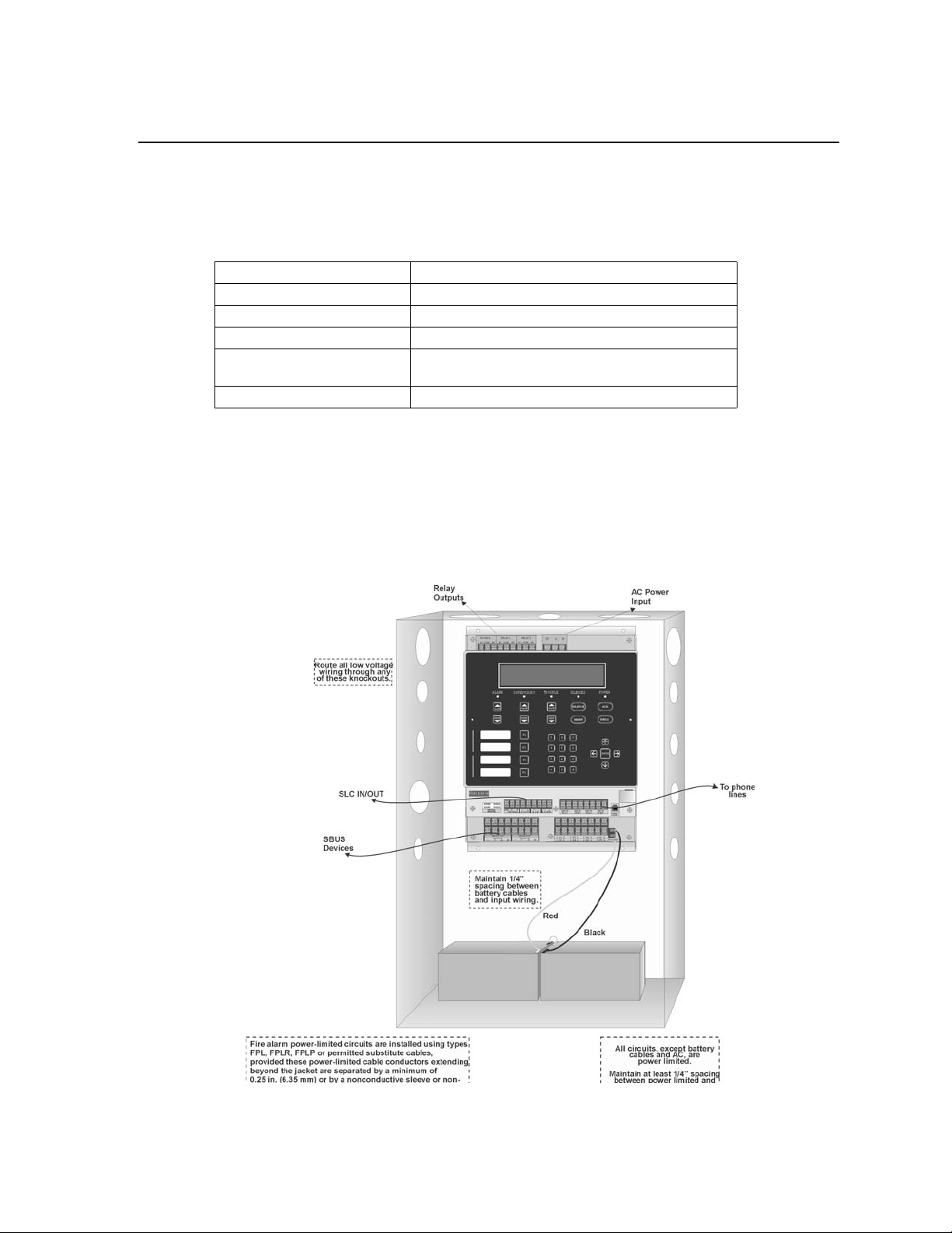
LS10143-001SK-E Before You Begin Installation
3.5 Wiring Specifications
Induced noise (transfer of electrical energy from one wire to another) can interfere with telephone
communication or cause false alarms. To avoid induced noise, follow these guidelines:
• Isolate input wiring from high current output and power wiring. Do not pull one multi-conductor cable for
the entire panel. Instead, separate the wiring as follows:
High voltage AC power terminal
SLC loops SLC In/Out Term inals
POTS reporting input/output Phone line circuits, Ring Tip Telco, Phone Terminals
Notification circuits I/01-I/08 Terminals
SBUS SBUS1 In/Out Terminals, SBUS 2 In/Out Te rminals,
Cellular communication
Relay circuits Trouble, Relay 1, Relay 2 Terminals
• Do not pull wires from different groups through the same conduit. If you must run them together, do so for
as short a distance as possible or use shielded cable. Connect the shield to earth ground at the panel. You
must route high and low voltages separately.
• Route the wiring around the inside perimeter of the cabinet. It should not cross the circuit board where it
could induce noise into the sensitive microelectronics or pick up unwanted RF noise from the high speed
circuits. See Figure 3-2 for an example.
• High frequency noise, such as that produced by the inductive reactance of a speaker or bell, can also be
reduced by running the wire through ferrite shield beads or by wrapping it around a ferrite toroid.
Figure 3-1 Wire Routing Example for 6820
3-4
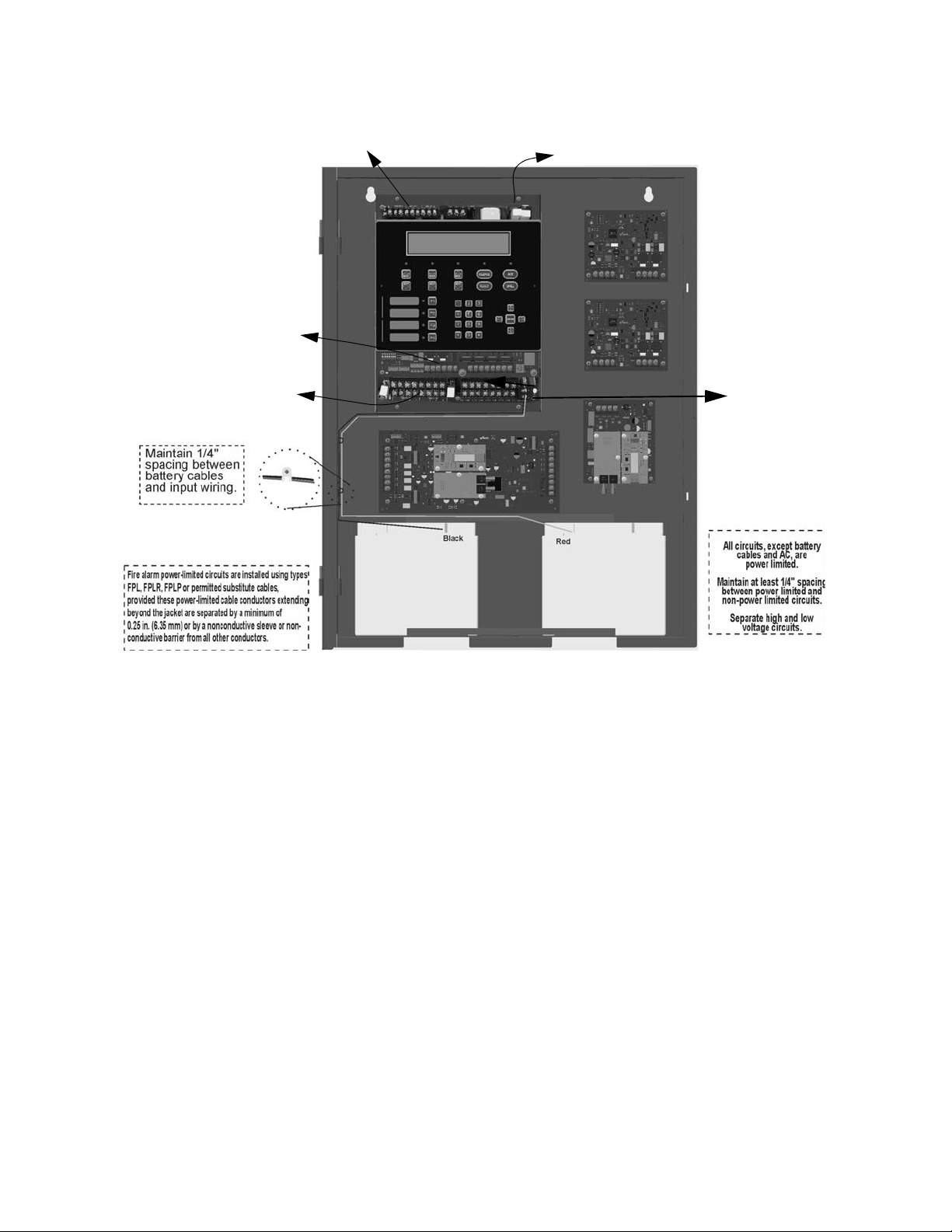
Model IFP-2100/ECS Installation Manual LS10143-001SK-E
Relay
outputs
AC Power
Input
lines
SLC
Devices
To Phone
SBUS Devices
Battery
Battery
Figure 3-2 Wire Routing Example for IFP-2100ECS
3-5
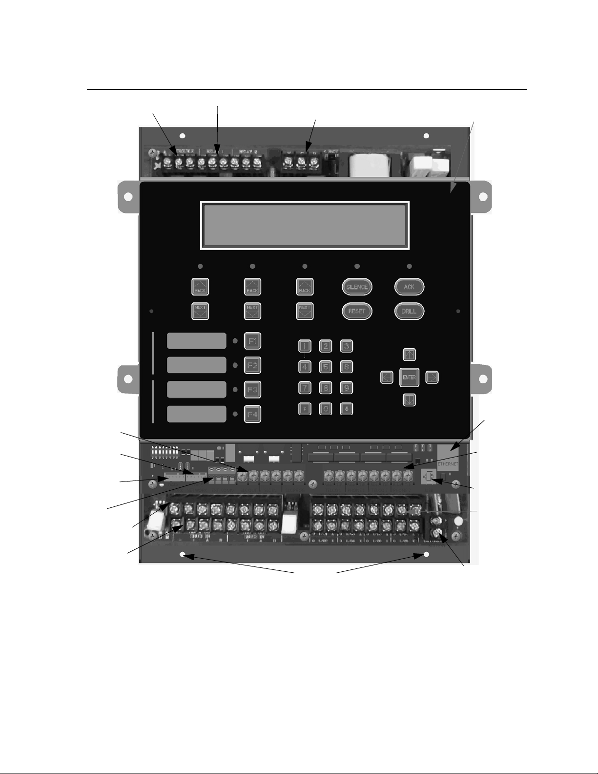
LS10143-001SK-E Before You Begin Installation
Chassis
Mounting
Nuts
On-board Annunciator
AC
Trouble
Relay
Phone lines
SLC
In/Out
Battery
Connections
Data
USB Port
Ethernet
Port
(non-power
limited)
Programmable
Alarm Relay
SBUS In
SBUS Out
Flexput
Circuits
Network
Voice
Network
IP
Communication
3.6 Board Assembly Diagram
Figure 3-3 Model IFP-2100 Assembly
Figure 3-3 shows th e circuit b oards, metal ho using and annunciat or that att ach the IFP-21 00/ECS assembly t o the
cabinet. If you should need to remove the board assembly for repair, remove the four mounting nuts which hold
the assembly in the cabinet. Then lift the entire assembly out of the cabinet. Do not attempt to remove the circuit
boards from the metal bracket.
3-6

Model IFP-2100/ECS Installation Manual LS10143-001SK-E
3.7 Calculating Current Draw and Standby Battery
This section is for helping you determine the current draw and standby battery needs for your installation.
3.7.1 Current Draw Worksheet Requirements
The following steps must be taken when determining IFP-2100/ECS current draw and standby battery
requirements.
1. You will use the Current Draw Worksheet to determine current draw and standby battery requirements. Use
Table 3-2 if installing IDP SLC Devices, Table 3-3 if installing SK SLC Devices or use Table 3-4 if installing SD SLC Devices For the IFP-2100/ECS, the worst case current draw is listed for the panel, addressable
devices, and all SBUS expanders. Fill in the number of addressable devices and expanders that will be used
in the system and compute the current draw requirements for alarm and standby. Record this information in
the current draw worksheet on Line A.
2. Add up the current draw for all auxiliary devices and record in the table on Line B.
3. Add up the current draw for all notification appliance loads and record in the table on Line C.
4. For notification appliances and auxiliary devices not men tioned in the manual, refer to the device manu al for
the current ratings.
5. Make sure that the total alarm current you calculated, including current for the panel itself, does not exceed
9.0 A. This is the maximum alarm current for the IFP-2100/ECS control panel. If the current is above 9.0 A
you will need to use a notification power expander(s) such as the 5496 or the RPS-1000 intelligent power
expander, to distribute the po wer loads so that the IFP-2100/ECS or the power expanders do not exceed their
power ratings. Refer to the current draw worksheets provided with the 5496 or the RPS-1000 manuals so
you do not exceed their power ratings.
6. Alternatively, you may network additional IFP-2100/ECS or RFP-2100s to get additional power.
7. Complete the remaining instructions in the appropriate current draw worksheet for determining battery size
requirements.
3.7.2 Current Draw Worksheet for IDP SLC Devices
Use Ta ble 3-2 to determine current requiremen ts during alarm/battery standby operation when IDP SLC devices
are installed. You can install up to 159 IDP sensors per loop (2100 points max per panel) and 159 IDP modules
per loop (2100 points max per panel). Copy this section if additional space is required.
Table 3-2: Current Draw Worksheet for IDP SLC Devices
Device # of Devices Current per Device
For each device use this formula: This column X This column = Current per number of devices.
Fire Panel (Battery current draw) 1
Standby: 230 mA 230 mA
Alarm: 415 mA 415 mA
Standby
Current
Alarm
Current
3-7

LS10143-001SK-E Before You Begin Installation
Table 3-2: Current Draw Worksheet for IDP SLC Devices
Device # of Devices Current per Device
Addressable SLC Devices
IDP-Photo
IDP-Photo-T mA mA
IDP-PhotoR mA mA
IDP-Heat mA mA
IDP-Heat-HT mA mA
IDP-Acclimate
IDP-Heat-ROR mA mA
IDP-Beam (without integral test)
IDP-Beam-T
DNR
DNR
IDP-CO-Fire
IDP-Monitor
IDP-Minimon mA mA
IDP-Pull-SA/IDP-Pull-DA mA mA
IDP-Monitor-2 Standby/Alarm: .75 mA mA mA
IDP-Monitor-10 S tandby/Alarm: 3.5 mA mA mA
IDP-Control
IDP-Control-6
IDP-Relay Standby/Alarm: .255 mA mA mA
IDP-Relay-6 Standby/Alarm: 1.45 mA mA mA
IDP-RelayMon-2
IDP-Zone
IDP-Zone-6
5
6
(non-relay)
7
(with relay)
(with integral test)
Standby: .30 mA
Standby: .30 mA
SLC Standby/Alarm: 2 mA mA mA
Aux. Pwr Standby: 2 mA mA
Alarm: 8.5 mA mA
SLC Standby/Alarm: 2 mA mA mA
Aux. Pwr Standby: 2 mA m A
Alarm: 8.5 mA mA
None, included with IDP-PhotoR
None, included with IDP-PhotoR & IDP-Relay
SLC Standby: .30 mA mA
Alarm: 7.2 mA mA
Standby/Alarm .375 mA
SLC Standby .375 mA mA
Alarm: .375 mA mA
Aux Pwr Standby 1.7 mA mA
Alarm: 7mA mA
SLC Standby 2.25 mA mA
Alarm: 2.25 mA mA
Aux Pwr Standby 8 mA mA
Alarm: 20 mA mA
Standby: 1.3 mA mA
Alarm: 24 mA mA
Aux Pwr Standby 12 mA mA
Alarm: 90 mA mA
SLC Standby/Alarm .27 mA mA mA
Aux Pwr Standby 50 mA mA
Alarm: 70 mA mA
SLC Standby/Alarm 2 mA mA mA
Standby
Current
1
1
Alarm
Current
mA mA
mA mA
mA mA
3-8

Model IFP-2100/ECS Installation Manual LS10143-001SK-E
Table 3-2: Current Draw Worksheet for IDP SLC Devices
Device # of Devices Current per Device
SLC Accessories
Aux Pwr Standby: .5 mA mA
B200SR Sounder Base
SLC Standby .3 mA mA
Aux Pwr Standby: .5 mA mA
B200S Intelligent Sounder Base
SLC Standby .3 mA mA
B200SR-LF Low Frequency Sounder
Base
B200S-LF Low Frequency Sounder
Base
B224RB Relay Base Standby/Alarm: .5 mA mA mA
RT151/151 KEY Alarm: 7.5 mA
RA100Z Alarm: 10 mA
SLC Isolator Devices
IDP-ISO (Isolator Module)
(318 max/loop
ISO-6 (6 Fault Isolator Module)
B224BI Isolator Base Standby/Alarm: 0.5 mA mA mA
Accessories Modules
6815 SLC Loop Expander
RA-2000 Remote LCD Annunciator
RA-1000 Remote LCD Annunciator
& 2100 max/
panel)
(63 max)
(63 max)
(31 max)
RA-100 Remote LCD Annunciator
5824 Serial/Parallel Module (4 max.) Standby/Alarm: 45 mA mA mA
5496 NAC Expander
RPS-1000 Power Supply Standby/Alarm: 10 mA mA mA
5865-4 LED Annunciator
(with reset and silence switches)
5865-3 LED Annunciator Module
5880 LED I/O Module
5883 Relay Interface
ESC-50W or ECS-125W Voice
Amplifier with/without ECS-CE4
(63 max)
(63 max)
(63 max)
(63 max)
(16 max.)
Aux Pwr Standby: 1 mA mA
Aux Pwr Standby .55 mA mA
SLC Standby .30 mA mA
Standby/Alarm: 0.45 mA mA mA
Standby: (per circuit) .45 mA mA
Alarm: (per circuit) 17 mA mA
Standby: 78 mA mA
4
Alarm: 78 mA mA
Standby: 20 mA mA
4
Alarm: 25 mA mA
Standby: 20 mA mA
Alarm: 25 mA mA
Standby: 25 mA mA
Alarm: 50 mA mA
Standby/Alarm: 10 mA mA mA
4
Standby: 35 mA mA
4
Alarm: 145 mA mA
Standby: 35 mA mA
Alarm: 145 mA mA
4
Standby: 35 mA mA
Alarm: 200 mA mA
Standby: 0 mA mA
4
Alarm: (22 mA/relay) 220 mA mA
Standby 10 mA mA
Alarm 10 mA mA
Alarm: 35 mA mA
Alarm: (high vol) 35 mA mA
Alarm: 125 mA mA
Alarm (high vol) 140 mA mA
Standby
Current
Alarm
Current
mA
mA
3-9

LS10143-001SK-E Before You Begin Installation
Table 3-2: Current Draw Worksheet for IDP SLC Devices
Device # of Devices Current per Device
Standby: 52 mA mA
ECS-INT50W Internal Amplifier (16 max.)
ECS-DUAL50W Dual Voice Amp (16 max.) Standby/Alarm: 10 mA mA mA
ECS-50WBU Back-Up Amplifier (16 max.) Standby/Alarm: 10 mA mA mA
ECS-VCM Voice Control Module
ECS-NVCM Voice Control Module Standby/Alarm: 59 mA mA mA
ECS-SW24 Switch Expander (32 max.)
ECS-RPU Remote Paging Unit
ECS-LOC Local Operating Console
(includes RA-2000, RVM & SW-24)
Network Cards
SK-NIC Network Interface Card (1 Max.) Standby/Alarm: 21 mA mA mA
SK-FML Fiber Optic Multi Mode (1 Max.) Standby/Alarm: 53 mA mA mA
SK-FSL Fiber Optic Single Mode (1 Max.) Standby/Alarm: 79 mA m A mA
Wireless Modules
WIDP-WGI Wireless Gateway
Total System Current
Auxiliary Devices
IPDACT-2 IP Communicator (1 max.)
IPDACT-2UD IP Communicator (1 max.)
CELL-MOD/CELL-CAB-SK
Auxiliary Devices Current
Notification Devices Refer to device manual for current rating
5495/5499 Power Supply 24 VDC
Notification Appliances Current
Total current ratings of all devices in system (line A + line B + C) mA mA
Total current ratings converted to amperes (line D x .001): A A
2
(1 max.)
(15 max.)
Alarm @ 25V: 275 mA mA
Alarm @ 70V: 310 mA
Standby: 70 mA mA
Alarm: 100 mA mA
Standby: 10 mA mA
Alarm: 25 mA mA
Standby: 70 mA mA
Alarm: 100 mA mA
Standby: 105 mA mA
Alarm: 175 mA mA
Max current using ext supply 40 mA mA mA
Max current SLC Power 24 mA mA mA
Refer to devices manual for current rating
Standby: 93 mA mA
Alarm: 136 mA mA
Standby: 98 mA mA
Alarm: 155 mA mA
Standby: 55 mA mA
Alarm: 100 mA mA
Alarm/Standby: mA mA mA
Alarm/Standby: mA mA mA
Alarm/Standby: mA mA mA
One input circuit: 15 mA
Both input circuits: 30 mA
Alarm: mA
Alarm: mA
Alarm: mA
Standby
Current
Alarm
Current
mA
mA
mA
mA
mA
mA
mA
3-10

Model IFP-2100/ECS Installation Manual LS10143-001SK-E
Table 3-2: Current Draw Worksheet for IDP SLC Devices
Device # of Devices Current per Device
Number of standby hours H
Multiply lines E and F. Tot a l s tandby AH AH
Alarm sounding period in hours. (For example, 5 minutes = .0833 hours) H
Multiply lines E and H. Total alarm AH
Add lines G and I.
Multiply by the Derating Factor x 1.25
3
Total ampere hours
required
Standby
Current
Alarm
Current
AH
AH
1. The FACP can only support 5 devices w/LED’s on. The current draw has been added to the panels alarm current.
2. If using door holders, you do not need to consider door holder current f or alarm/battery standby, because power is removed
during that time. However, during normal operation, door holders draw current and must be included in the 9.0A total current
that can be drawn from the panel.
3. Use next size battery wit h capacity greate r than required.
4. Maximum SBUS address capacity is 63 SBUS modules. The practical limit is determined by the amount of SBUS bandwidth
consumed by each SBUS modul e . See section 4.13.2.
5. The
IDP-Beam-T draws a maximum of 500mA from auxiliary power when the test feature is used. This should be considered
when determining auxiliary power capacity but not calculated into current requirements for day to day operation.
6. The IDP-PhotoR is sold separately from the DNR. Current draw for the DNR + IDP-PhotoR is calculated by increasing the
“Number of Devices” column f or each IDP-PhotoR used with a DNR .
7. The DNR housing does not include a Relay circuit bo ard. If a relay is needed, be sure to add one to the IDP-Relay & IDP-PhotoR “Number of Devices” column for each DNR used for correct current calculations.
3.7.3 Current Draw Worksheet for SK SLC Devices
Use Table 3-3 to determine current requirements during alarm/battery standby operation when SK SLC devices
are installed. You can install up to 159 SK sensors per loop (2100 points max per panel) and 159 modules per
loop (2100 points max per panel).
Table 3-3 Current Draw Worksheet for SK SLC Devices
Device # of Devices Current per Device
For each device use this formula: This column X This column = Current per number of devices.
Fire Panel (Battery current draw) 1
Standby: 230 mA 230 mA
Alarm: 415 mA 415 mA
Standby
Current
Alarm
Current
3-11

LS10143-001SK-E Before You Begin Installation
Table 3-3 Current Draw Worksheet for SK SLC Devices
Device # of Devices Current per Device
Addressable SLC Detectors
SK-PHOTO
SK-PHOTO-T mA mA
SK-HEAT mA mA
SK-HEAT-HT mA mA
SK-ACCLIMATE mA mA
SK-HEAT-ROR mA mA
5
SK-DUCT
SK-BEAM (without integral test)
SK-BEAM-T
SK-FIRE-CO
Addressable SLC Module
SK-MONITOR
SK-MINIMON mA mA
SK-PULL-SA mA mA
SK-PULL-DA mA mA
SK-MONITOR-2 Standby/Alarm: .75 mA mA mA
SK-MON-10 Standby/Alarm: 3.5 mA mA mA
SK-CONTROL
SK-CONTROL-6
SK-RELAY Standby/Alarm: .255 mA mA mA
SK-RELAY-6 Standby/Alarm: 1.45 mA mA mA
SK-RELAYMON-2
SK-ZONE
SK-ZONE-6
(includes PhotoR)
4
(with integral test)
Standby/Alarm: .30 mA
SLC Standby/Alarm: 2 mA
Aux. Pwr Standby: 2 mA mA
Alarm: 8.5 mA mA
SLC Standby/Alarm: 2 mA
Aux. Pwr Standby: 2 mA mA
Alarm: 8.5 mA mA
SLC Standby: .30mA mA
Alarm: 7.2mA mA
Standby/Alarm: .375 mA
SLC Standby: .375 mA mA
Alarm: .375 mA mA
Aux Pwr Standby: 1.7 mA mA
Alarm: 7 mA mA
SLC Standby: 2.25 mA mA
Alarm: 2.25 mA
Aux Pwr Standby: 8 mA mA
Alarm: 20 mA mA
Standby: 1.3 mA mA
Alarm: 24 mA mA
Aux Pwr Standby 12 mA mA
Alarm 90 mA mA
SLC Standby/
Alarm .27 mA
Aux Pwr Standby 50 mA mA
Alarm 270 mA mA
SLC Standby/Alarm 2 mA mA mA
Standby
Current
mA mA
1
mA mA
mA mA
mA mA
Alarm
Current
3-12

Model IFP-2100/ECS Installation Manual LS10143-001SK-E
Table 3-3 Current Draw Worksheet for SK SLC Devices
Device # of Devices Current per Device
SLC Modules
Aux Pwr Standby: .5mA mA
B200SR Sounder Base
SLC Standby .3 mA mA
Aux Pwr Standby: .5 mA mA
B200S Intelligent Sounder Base
SLC Standby .3 mA mA
B200SR-LF Low Frequency Sounder
Base
B200S-LF Low Frequency Sounder
Base
B224RB Relay Base Standby/Alarm: 0.5 mA mA mA
RTS151/151 KEY Alarm: 7.5 mA
RA100Z Alarm: 10 mA
SLC Isolator Devices
SK-ISO (Isolator Module) (318 max /loop
B224BI Isolator Base
Accessories Modules
6815 SLC Loop Expander (63 max.) Standby/Alarm: 78 mA mA mA
RA-2000 Remote LCD Annunciator
RA-1000 Remote LCD Annunciator
RA-100 Remote LCD Annunciator
5824 Serial/Parallel I/O Module (4 max.) Standby/Alarm: 45 mA mA mA
5895XL Power Supply
5496 NAC Expander Standby/Alarm: 10 mA mA mA
5865-4 LED Annunciator
(with reset and silence switches)
5865-3 LED Annunciator
5880 I/O Module
5883 Relay Interface (63 max.)
ECS-50W or ECS-125W Audio
Amplifier with/without EVS-CE4
ECS-INT50W Internal Amplifier (16 max.)
& 2100 max/
panel)
(63 max)
(31 max.)
(63 max.)
63 (max.)
(16 max.)
Aux Pwr Standby: 1 mA mA
Aux Pwr Standby .55 mA mA
SLC Standby .30 mA mA
Standby/Alarm: .45 mA mA mA
Standby/Alarm: .5 mA mA mA
Standby: 20 mA mA
4
Alarm: 25 mA mA
Standby: 20 mA mA
Alarm: 25 mA mA
Standby: 25 mA mA
Alarm: 50 mA mA
Standby/Alarm: 10 mA mA mA
Standby: 35 mA mA
Alarm: 145 mA mA
Standby: 35 mA mA
Alarm: 145 mA mA
Standby: 35 mA mA
Alarm: 200 mA mA
Standby: 0 mA mA
Alarm: 220 mA
(22 mA per relay)
Standby: 10 mA mA
Alarm: 10 mA mA
Standby: 52 mA mA
Alarm @ 25V: 275 mA mA
Alarm @ 70V: 310 mA
Alarm: 35mA mA
Alarm: (high vol) 35 mA mA
Alarm: 125 mA mA
Alarm (high vol) 140 mA mA
Standby
Current
Alarm
Current
mA
mA
mA
mA
3-13

LS10143-001SK-E Before You Begin Installation
Table 3-3 Current Draw Worksheet for SK SLC Devices
Device # of Devices Current per Device
ECS-VCM Voice Control Module
ECS-NVCM Voice Control Module Standby/Alarm: 59 mA mA mA
ECS-SW24 Switch Expander (32 max.)
ECS-RPU Remote Paging Unit
ECS-LOC Local Operating Console
(includes RA-2000, RVM & SW-24)
Network Cards
SK-NIC Network Interface Card (1 Max.) Standby/Alarm: 21 mA mA mA
SK-FML Fiber Optic Multi Mode (1 Max.) Standby/Alarm: 53 mA mA mA
SK-FSL Fiber Optic Single Mode (1 Max.) Standby/Alarm: 79 mA mA mA
Wireless Modules
SK-WGI Wireless Gateway
Auxiliary Devices
IPDACT-2 IP Communicator (1 max.)
IPDACT-2UD IP Communicator (1 max.)
CELL-MOD/CELL-CAB-SK
Notification Appliance Circuits Refer to device manual for current rating.
5495/5499 Power Supply 24 VDC
Total current ratings of all devices in system (line A + line B + C) mA mA
Total current ratings converted to amperes (line D x .001): A A
Number of standby hours: H
Multiply lines E and F. Total standby AH AH
Alarm sounding period in hours. (For example, 5 minutes = .0833 hours) H
Multiply lines E and H. Total alarm AH
Add lines G and I.
Multiply by the Derating Factor x 1.25
2
3
(1 max.)
(15 max.)
Standby: 70 mA mA
Alarm: 100 mA mA
Standby: 10 mA mA
Alarm: 25 mA mA
Standby: 70 mA mA
Alarm: 100 mA mA
Standby: 105 mA mA
Alarm: 175 mA mA
Total System Current
Max current using ext supply 40 mA mA mA
Max current SLC Power 24 mA mA mA
Total System Current
Refer to devices manual for current rating.
Standby: 93 mA mA
Alarm: 136 mA mA
Standby: 98 mA mA
Alarm: 155 mA mA
Standby: 55 mA mA
Alarm: 100 mA mA
Alarm/Standby: mA mA mA
Alarm/Standby: mA mA mA
Alarm/Standby: mA mA mA
Alarm/Standby: mA mA mA
Auxiliary Devices Current
One input circuit: 15 mA
Both input circuits: 30 mA
Alarm: mA
Alarm: mA
Alarm: mA
Alarm: mA
Notification Appliances Current
Standby
Current
AH
Alarm
Current
mA
mA
mA
mA
mA
mA
mA
AH
3-14

Model IFP-2100/ECS Installation Manual LS10143-001SK-E
Table 3-3 Current Draw Worksheet for SK SLC Devices
Device # of Devices Current per Device
Total ampere hours
required
1. The FACP can only support 5 devices w/LED’s on. This current draw has been added to the panels alarm current.
2. If using door holders, you do not need to consider door holder current for alarm/battery standby , because power is removed during
that time. However, during normal operation, door holders draw current and must be included in the 6.0A total current that can be
drawn from the panel.
3. Use next size battery with capacity greater than required.
4. SK-BEAM-T draws a maximum of 500mA from Auxiliary power only when the test feature is used. this should be considered when
determining auxiliary power capacity but not calculated into current requirements for day to day operation.
5. The SK-DUCT housing contains a vacant mount for a SK-RELAY (sold separately). Current draw for the SK-RELAY is calculated
by increasing the SK-RELAY row of the calculation sheet by one for each SK-RELAY used with a SK-DUCT.
Standby
Current
Alarm
Current
3.7.4 Current Draw Worksheet for SD SLC Devices
Use Table 3-4 to determine current requirements during alarm/battery standby operation when SD SLC devices
are installed. You can install up to 127 SD devices per loop (2032 max per panel). Copy this sect ion i f add i tio nal
space is required.
Device # of Devices Current per Device
For each device use this formula: This column X This column = Current per number of devices.
1
Table 3-4: Current Draw Worksheet for SD SLC Devices
Standby
Current
Alarm Current
Fire Panel (Battery current draw) 1
SD500-AIM
SD500-MIM mA mA
SD500-PS mA mA
SD500-ARM mA mA
SD505-HEAT mA mA
SD505-PHOTO mA mA
SD500-ANM
SD500-SDM
SLC Accessory Base
SD505-6RB Standby/Alram: .082 mA mA mA
SD505-6SB
Standby: 230 mA 230 mA
Alarm: 415 mA 415 mA
mA mA
Standby/Alarm: .55 mA
Aux. Pwr
SLC Standby/Alarm: .55 mA mA mA
SLC Standby/Alarm: .55 mA mA mA
Aux. Pwr
Aux. Pwr
SLC Standby/Alarm: .082 mA mA mA
Standby: 8 mA mA
Alarm: 60 mA mA
Standby: 20 mA m A
Alarm: 106 mA mA
Standby: 1 mA mA
Alarm: 32 mA mA
6
3-15

LS10143-001SK-E Before You Begin Installation
Table 3-4: Current Draw Worksheet for SD SLC Devices
2
2
Standby
Current
Alarm Current
mA
mA
mA
mA
mA
mA
Device # of Devices Current per Device
Aux. Pwr
SD505-DUCTR
SLC Standby/Alarm: .5mA mA mA
SD505-DTS-K None, included with SD505-DUCTR worst case.
SD505-DUCT SLC Standby/Alarm .5mA mA mA
SLC Isolator Devices
SD505-LIM (1272 max.)
SD505-6IB (2032 max.)
Accessories Modules
5815XL SLC Expander
RA-2000 Remote LCD
Annunciator
RA-1000 Remote LCD
Annunciator
RA-100 Remote LCD
Annunciator
5824 Serial/Parallel Printer
Interface Module
5496 NAC Expander
RPS-1000 Power Supply Standby/Alarm: 10mA mA mA
(63 max.)
(63 max)
(4 max.) Standby/Alarm: 45mA mA mA
(63 max.)
Standby/Alarm .092mA mA mA
5
Standby/Alarm: 55mA mA mA
Standby: 20mA
Alarm: 25mA
Standby: 20mA
4
Alarm: 25mA
Standby: 25mA mA
Alarm: 50mA mA
Standby/Alarm: 10mA mA mA
5
Standby: 20 mA
Alarm: 62 mA
5865-4 LED Annunciator
(with reset and silence switches)
5865-3 LED Annunciator
5880 LED I/O Module
5883 Relay Interface
ECS-VCM Voice Control Module
ECS-NVCM Network Voice
Control Module
ECS-SW24 Switch Expander (32 max.)
ECS-50W or ECS-125W Audio
Amplifier with/without ECS-CE4
ECS-INT50W Internal Amplifier (16 max.)
(63 max.)
(63 max.)
(63 max.)
(1 max.)
(16 max.)
Standby: 35mA mA
5
Alarm: 145mA mA
Standby: 35mA mA
Alarm: 145mA mA
5
Standby: 35mA mA
Alarm: 200mA mA
Standby: 0mA mA
5
Alarm: 220mA (22 mA per relay) mA
Standby: 70mA mA
Standby/Alarm: 59mA mA mA
Standby: 10mA mA
Alarm: 25mA mA
Standby: 10mA mA
Alarm: 10mA mA
Standby: 52mA mA
Alarm @ 25V: 275mA mA
Alarm @ 70V: 310mA
mA
3-16

Model IFP-2100/ECS Installation Manual LS10143-001SK-E
Table 3-4: Current Draw Worksheet for SD SLC Devices
Device # of Devices Current per Device
ECS-RPU Remote Paging Unit
ECS-LOC Local Operating
Console (includes RA-2000,
RVM & SW-2 4)
ECS-DUAL50W Dual Voice Amp (16 max.) Standby/Alarm: 10 mA mA mA
ECS-50WBU Back-Up Amplifier (16 max.) Standby/Alarm: 10 mA mA mA
Network Cards
SK-NIC Network Interface Card (1 Max.) Standby/Alarm: 21 mA mA mA
SK-FML Fiber Optic Multi Mode (1 Max.) Standby/Alarm: 53 mA mA mA
SK-FSL Fiber Optic Single Mode (1 Max.) Standby/Alarm: 79 mA mA mA
A Total System Current
Auxiliary Devices
IPDACT-2 IP Communicator
IPDACT-2UD IP Communicator
CELL-MOD/CELL-CAB-SK
B Auxiliary Devices Current
Notification Devices Refer to devices manual for current rating.
5495/5499 Power Supply 24 VDC
C Notification Appliances Current mA
D Total current ratings of all devices in system (line A + line B + C) mA mA
E Total current ratings converted to amperes (line D x .001): A A
F Number of standby hours H
G Multiply lines E and F. Total standby AH AH
H Alarm sounding period in hours. (For example, 5 minutes = .0833 hours) H
I Multiply lines E and H. Total alarm AH
J
Add lines G and I.
Multiply by the Derating Factor
3
4
(15 max.)
Standby: 70 mA mA
Alarm: 100 mA mA
Standby: 105 mA mA
Alarm: 175 mA
Refer to devices manual for current rating.
Alarm: 136 mA
Standby: 93 mA mA
Alarm: 155 mA
Standby: 98 mA mA
Standby: 55 mA mA
Alarm: 100 mA mA
Alarm/Standby: mA mA m A
Alarm/Standby: mA mA m A
Alarm/Standby: mA mA mA
One input circuit: 15 mA
Both input circuits: 30 mA
Alarm: mA
Alarm: mA
Alarm: mA
Alarm: mA
Standby
Current
x 1.25
Alarm Current
mA
mA
mA
mA
mA
mA
mA
mA
mA
AH
AH
1. Total does not include isolator devices or accessory bases.
Total ampere hours
required
3-17

LS10143-001SK-E Before You Begin Installation
2. If using 24 VDC aux power only. No standby or alarm cur rent for battery calculation if using 24VAC, 120VAC or 240VAC.
3. If using door holders, you do not need to consider door holder current f or alarm/battery standby, because power is removed
during that time. However, during normal operation, door holders draw current and must be included in the 9.0A total current
that can be drawn from the panel.
4. Use next size battery wit h capacity greate r than required.
5. Maximum SBUS address capacity is 63 SBUS modules. The practical limit is determined by the amount of SBUS bandwidth
consumed by each SBUS modul e . See section 4.13.2.
6. The FACP can only support 2 devices w/LED’s on. The current draw has been added to the panels alarm current.
3-18

Model IFP-2100/ECS Installation Manual LS10143-001SK-E
3.7.5 Maximum Battery Standby Load
Table 3-5 and Table 3-6 show the standby load calculations for the IFP-2100 based on 24 and 90 hours of
standby. The standby load calculations of line D in the Current Draw Calculation Worksheet must be less than
the number shown in Table 3-5 and Table 3-6 for the selected battery size, standby hour and alarm time. The
numbers below have a built in 20% derating factor for the battery amp-hour capacity.
Table 3-5: Maximum Battery Standby Loads for 24 Hour Standby
Rechargeable
Battery Size
17AH 535 mA 473 mA 442 mA
18AH 569 mA 506 mA 475 mA
24AH 769 mA 706 mA 675 mA
33AH 1.07A 1.01A 975 mA
35AH 1.14A 1.07A 1.04A
40AH 1.30A 1.24A 1.21A
55AH 1.80A 1.74A 1.71A
24 hr Standby,
5 mins. Alarm
24 hr Standby,
15 min alarm
24 hr Standby,
20 min alarm
Table 3-6: Maximum Battery Standby Loads for 90 Hour Standby*
Rechargeable
Battery Size
33 AH N/A N/A N/A
40 AH 347 mA 331 mA 322 mA
55 AH 480 mA 464 mA 456 mA
90 hr Standby ,
5 min alarm
90 hr Standby,
15 min alarm
90 hr Standby,
20 min alarm
Warning
Honeywell Silent Knight does not support the use of batteries smaller than those listed in Table 3-5 and Table 3-6. If you
use a battery too small for the installation, the system could overload the battery resulting in the installation having less
than the required 24 hours standby power. Use Table 3-5 and Table 3-6 to calculate the correct battery amp hour rating
needed for your installation. It is recommended that you replace batteries every five years.
*For FM Installation only
3-19

Model IFP-2100/ECS Installation Manual LS10143-001SK-E
IFP-2100ECS
IFP-2100
24.75"
14.5"
20"
26.5"
Section 4 Control Panel Installation
4.1 Mounting the Control Panel Cabinet
Read the environmental specifications in Section 3.2 before mounting the control panel cabinet. This will ensure
that you select a suitable location.
The IFP-2100 cabinet can be surface or flush mounted. Cabinet base dimensions are 24¾” H x 14.5" W. If you
flush mount there sho uld be 1.5" t o 1.75" of cab inet extr uding fr om the wall, t his should be measu red from either
the top edge or bottom edge to the exterior side of the sheet rock. Do NOT flush mount in a wall designated as a
fire break.
The IFP-2100/ECS cabinet can be surface or flush mounted. Cabinet base dimensions are 26½” H x 20"W. If
you flush mount the cabinet, there should be 1.5" to 1.75" of cabinet extruding from the wall, this should be
measured from either the top edge or bottom edge to the exterior side of the sheet rock. Do NOT flush mount in
a wall designated as a fire break.
Figure 4-1 FACP Cabinet Mounting
4.1.1 Preventing Water Damage
Water damage to the fire system can be caused by moisture entering the cabinet through the conduits. Conduits
that are installed to enter the top of the cabinet are most likely to cause water problems. Installers should take
reasonable precautions to prevent water from entering the cabinet. Water damage is not covered under warranty.
4-1

LS10143-001SK-E Control Panel Installation
240VAC models
are labeled
here
4.1.2 Removing the IFP-2100/ECS Assembly from the Housing
Should it ever be necessary to remove the control panel assembly from the cabinet for repair, do so by
unscrewing the nuts that connect the control panel assembly to the cabinet. Do not attempt to disassemble the
circuit boards.
4.1.3 Ethernet Connection
Ethernet connect for IP communication. For port location see Figure 3-3.
4.2 AC Power Connection
WARNING: RISK OF ELECRICAL SHOCK AND EQUIPMENT DAMAGE
SEVERAL DIFFERENT SOURCES OF POWER CAN BE CONNECTED TO THIS PANEL. DISCONNECT ALL
SOURCES OF POWER BEFORE SERVICING. THE PANEL AND ASSOCIATED EQUIPMENT MAY BE
DAMAGED BY REMOVING AND/OR INSERTING CARDS, MODULES OR INTERCONNECTING CABLES
WHILE THIS UNIT IS ENERGIZED
The AC terminals are rated at 120VAC, 50 or 60 Hz, 5A (for the IFP-2100/ECS) or 240VAC, 50 or 60 Hz, 2.8A
(for the IFP-2100/ECSHV).)
Figure 4-2 120 VAC Power Connection for the IFP-2100/ECS
Figure 4-3 240VAC Power Connection for the IFP-2100/ECSHV
4-2

Model IFP-2100/ECS Installation Manual LS10143-001SK-E
Red
Black
Battery Jumper
(P/N 140694)
Shipped With Panel
4.3 Battery Power
The batteries must be sealed lead acid type. Before connecting the batteries to the FACP, m a ke certain that the
interconnect cable between the batteries is not
system is completely installed. Observe polarity when connecting the batteries.
WARNING: RISK OF PERSONAL INJURY
Battery contains sulfuric acid which can cause severe burns to the skin and eyes and can destroy fabrics. If
contact is made with sulfuric acid, immediately flush the skin or eyes with water for 15 minutes and seek
immediate medical attention
The control panel battery charge capacity is 17 to 55 AH. Use 12V batteries of the same AH rating. Determine
the correct AH rating as per your standby load calculation (see Section 3.7).
Wire batteries in series to produce a 24-volt equivalent. Do not parallel batteries to increase the AH rating. It is
recommended that you replace batteries every five years.
connected. Do not connect the battery jumper cable until the
Figure 4-4 Battery Connection
4.3.1 Battery Accessory Cabinets
The Model RBB or AB-5 5 Accessory cabinets can be used when you are required to use backup batteries that are
too large to fit into the main control panel cabinet.
The RBB cabinet holds batt eries up to the 35 AH size. The RBB dimensions are 16" W x 10" H x 6" D ( 40.64 cm
W x 25.4 cm H x 15.24 cm D).
The AB-55 Accessory cabinet holds batteries up to the 55AH size. The AB-55 dimensions are 20" W x 11.5" H x
7.5" D (50.8 cm W x 30.48 cm H x 19.05 cm D).
4.3.1.1 Installing the RBB or AB-55 Accessory Cabinet and Batteries
To properly install the accessory cabinet and backup batteries, follow these steps:
1. Mount the accessory cabinet. See Figure 4-5 for the four cabinet mounting holes.
• If mounting onto drywall the accessory cabinet must be mounted onto ¾-inch plywood. This is necessary because the weight of the batteries inside the accessory cabinet could cause the cabinet to pull away from the drywall.
• When mounting on concrete, especially when moisture is expected, attach a piece of
4-3

LS10143-001SK-E Control Panel Installation
Cabinet
Mounting Holes
¾-inch plywood to the concrete surface and then attach the RBB or AB-55 cabinet to
the plywood.
• If using the battery cable extenders provided (P/N 140643), mount the RBB or AB-55
cabinet no more than 18" away from the main control panel cabinet. This will ensure
that the battery cables reach the battery terminals.
Figure 4-5 RBB or AB-55 Cabinet Mounting Holes
2. Connect the main control panel battery cables to the battery cable extenders as shown in Figure 4-6.
Figure 4-6 Splicing Control panel Battery Cable to RBB or AB-55 Battery Cable Extenders
4-4

Model IFP-2100/ECS Installation Manual LS10143-001SK-E
Conduit
Conduit
Coupler
+
+
-
-
RBB / AB-55 Cabinet
Cover Screws
RBB / AB-55 Cabinet
Cover Screws
Cover Plate
Mounting Keyholes
3. Run extended battery cable from control panel cabinet through conduit to RBB or AB-55 cabinet. See Figure 4-7.
Figure 4-7 Battery Connections in the RBB or AB-55 Cabinet
Note: Figure 4-7 is an example of how the wire connections can be routed. However, any other cabinet knock-
outs (on either the main control panel or the RBB/AB-55 cabinet), that are not previously b eing u sed may
be utilized to connect conduit between the two cabinets.
4. Connect battery leads to the backup battery terminals. See Figure 4-7.
• Observe the proper polarity to prevent damage to the batteries or the control panel.
5. Insert the RBB or AB-55 cover screws into the cover mounting holes. See Figure 4-7.
• Screw the cover screw ¾ of the way into the cover mounting hole.
6. Align the cover plate mounting keyhole over the cover mounting screws. See Figure 4-8.
Figure 4-8 Cover Plate Mounting Keyholes and Cover Mounting Screws Alignment
7. Slide the cover into place and tighten the cover mounting screws. See Figure 4-8.
4-5

LS10143-001SK-E Control Panel Installation
4.4 SBUS Wiring
This section contains information on calculating SBUS wire distances and the types of wiring configurations
(Class A and B).
4.4.1 Calculating Wiring Distance for SBUS Modules
The IFP-2100/ECS panel has tw o SB U S ci rcui ts w hich can support up to 1.0 A of module load per SBUS circuit.
When determining the type of wire and the maximum wiring distance that can be used, you will need to calculate
loads for each SBUS to ensure that each SBUS does not exceed 1.0A.
To calculate the wire gauge that must be used to connect SBUS modules to the control panel, it is necessary to
calculate the total worst case current draw for all modules on a single SBUS circuit. The total worst case current
draw is calculated by adding the individual worst case currents for each module. The individual worst case
values are shown in the table below.
Note: Total worst case current draw on a single SBUS cannot exceed 1 amp. If a large number of accessory mod -
ules are required, and the worst case curr ent draw will exceed the 2 amps total, then the current dr aw must
be distributed using RPS-1000 Power Expand ers. Each RPS-1000 Pow er Expander provides a n additional
SBUS, with an additional 1 amp of SBUS current. Wiring distance calculations are done separately for
each RPS-1000, and separately for each control panel SBUS.
Table 4-1: SBUS Device Current Draw
Model Number Worst Case Current Draw
RA-2000, RA-1000, RA-100 Fire Annunciator .120 amps
6815 SLC Loop Expander .078 amps
5815XL SLC Loop Expander .150 amps
5824 Serial/Parallel Printer Interface Module .040 amps
5880 LED I/O Module .250 amps
5865 LED Annunciator .200 amps
RPS-1000 Intelligent Power Supply .010 amps
5496 NAC Expander .010 amps
ECS-50W .010 amps
ECS-125W .010 amps
ECS-VCM / ECS-VCM with ECS-SW24* .1 15 amps /.185 amps
ECS-NVCM Network Voice Control Module .059 amps
ECS-EMG NVCM keypad .06 amps
ECS-LOC .210 amps /.325 amps
ECS-DUAL50W .010 amps
ECS-DUAL50W WITH ECS-50WBU .010 amps
SK-NIC Network Interface Card .021 amps
CELL-MOD/CELL-CAB-SK .145 amps
SK-F485C Fiber Converter .125 amps
Note: Refer to Table 3-2 if using IDP SLC devices, Table 3-3 for SK devices, and refer to Table 3-4 if using SD
SLC devices for maximum number of each type of device that can be used per system.
* All devices must use the same SBUS and VBUS.
After calculating the total worst case current draw, refer toTable 4-2 for the maximum distance the modules can
be located from the panel on a s ingle w ire ru n. The table ensures 6.0 v olts of l ine d rop maxi mu m. In gener a l, t he
wire length is limited by resistance, but for heavier wire gauges, capacitance is the limiting factor.
4-6

Model IFP-2100/ECS Installation Manual LS10143-001SK-E
These cases are marked in the chart with an asterisk (*). Maximum length can never be more than 6,000 feet,
regardless of gauge used. The formula used to generate this chart is shown in the note below.
Table 4-2: Wire Distances Per Wire Gauge Using Copper Wire
Wiring Distance: SBUS Modules to Panel
Total Worst Case
Current Draw (amps)
0.100 1852 ft. 4688 ft. * 6000 ft. * 6000 ft.
0.200 926 ft. 2344 ft. 3731 ft. 5906 ft.
0.300 617 ft. 1563 ft. 2488 ft. 3937 ft.
0.400 463 ft. 1172 ft. 1866 ft. 2953 ft.
0.500 370 ft. 938 ft. 1493 ft. 2362 ft.
0.600 309 ft. 781 ft. 1244 ft. 1969 ft.
0.700 265 ft. 670 ft. 1066 ft. 1687 ft.
0.800 231 ft. 586 ft. 933 ft. 1476 ft.
0.900 206 ft. 521 ft. 829 ft. 1312 ft.
1.000 (Max) 185 ft. 469 ft. 746 ft. 1181 ft.
22 Gauge 18 Gauge 16 Gauge 14 Gauge
Note: The following formulas were u sed to ge ner ate the wire distance chart:
Maximum Resistance (Ohms) = 6.0 Volts
Total Worst Case Current Draw (amps)
Maximum Wire Length (Feet) =
(6000 feet maximum)
where: Rpu = Ohms per 1000 feet for various wire gauges (see table below)
Maximum Resistance (Ohms) * 500
Rpu
Table 4-3: Typical Wire Resistance Per 1000 ft. Using Copper Wire
Wire Gauge Ohms per 1000 feet (Rpu)
22 16.2
18 6.4
16 4.02
14 2.54
Wiring Distance calculation example:
Suppose a system is configured with the following SBUS modules:
2 - Module RA-2000 Fire Annunciator
1 - RPS-1000 Intelligent Power Expander
1 - 5865 LED Annunciator
1 - 5824 Serial/Parallel Interface Module
4-7

LS10143-001SK-E Control Panel Installation
The total worst case current is calculated as follows:
RA-2000 Current Draw = 2 x .120 amps = .240 amps
RPS-1000 Current Draw = 1 x .010 amps = .010 amps
5865 Current Draw = 1 x .200 amps = .200 amps
5824 Current Draw = 1 x .040 amps = .040 amps
Total Worst Case Current Draw = .490 amps
Note: For assistance with SBUS calculat ion, please refer to www.farenhyt.com.
Using this value, and referring to the Wiring Distance table, it can be found that the available options are:
370 feet maximum using 22 Gauge wire
938 feet maximum using 18 Gauge wire
1493 feet maximum using 16 Gauge wir e
2362 feet maximum using 14 Gauge wir e
4-8

Model IFP-2100/ECS Installation Manual LS10143-001SK-E
Caution
For proper system supervision do not use looped
wire under terminals marked A, B, +, and - of the
SBUS device connectors. Break wire runs to provide
supervision of connections.
Supervised
Power Limited
Supervised
Power Limited
4.4.2 Wiring Configurations
Figure 4-9 illustrates SBUS 1, Class A wiring configuration and Figure 4-10 illustrates SBUS1 Class B
configuration. SBUS 2 wiring configurations are the same as SBUS1.
Figure 4-9 SBUS Class A Wiring
Figure 4-10 SBUS Class B Wiring
4-9

LS10143-001SK-E Control Panel Installation
4.5 RA-2000 Remote Annunciator Installation
The optional Model RA-2000 Remote Annunciator, shown in Figure 4-11. The RA-2000 can be surface or flush
mounted. It is available in gray color as RA-2000GRAY.
Figure 4-11 Model RA-2000 Remote Annunciator, Front View
RA-2000 installation involves the following steps:
1. Make sure power is off at the panel.
2. Mount the RA-2000 in the desired location (see Section 4.5.1).
3. Connect the RA-2000 to the panel (see Section 4.5.2).
4. Use the DIP switches on the back of the RA-2000 to assign an SBUS ID# to the RA-2000 (see Section
4.13.1).
5. The RA-2000 module must be added to the system through programming. JumpStart will add the module
automatically (see Section 8.1). You can also add it manually (see Section 9.2.2). Select a name, if desired
(see Section 9.2.1.2).
4.5.1 Mounting the RA-2000
4.5.1.1 Flush Mounting
This section of the manual describes flush mounting.
Follow these steps to flush mount the RA-2000
4-10

Model IFP-2100/ECS Installation Manual LS10143-001SK-E
Mounting Holes
Mounting Holes
Wire Knockouts
Wire Knockouts
Wire Knockouts
1. The backbox dimensions are 9 1/ 4” W x 8 3/8” H. The b ackbo x can be mou nte d p rior t o the complete installation of the RA-2000 using any of the mounting holes shown in Figure 4-12.
Figure 4-12 Backbox Mounting Holes
2. Remove knockout holes as needed for wires. See Figure 4-13 for backbox knockout locations.
Figure 4-13 Backbox Knockout Locations
3. Wire the annunciator board to the main control panel. As described in Section 4.5.2.
4-11

LS10143-001SK-E Control Panel Installation
key shaped
mounting hole
backbox
mounting holes
4. Attach the annunciator and door assembly to backbox as shown in Figure 4-14 using the supplied screws.
Figure 4-14 Attaching Annunciator / Door Assembly to Backbox
4.5.1.2 Surface Mounting
The Model RA -100TR red tr im ring and R A-2000GRAYTR gray trim ring kits are available for use when
surface mounting the RA-2000.
1. Remove the desired knock out. See Figure 4-13.
2. To properly mount the backbox, insert a single screw into the key shaped mounting hole. Do not tighten all
the way. See Figure 4-15.
Place a level on top of the backbox, with the backbox level insert the rest of the mounting screws
.
3. Run wires to the control panel.
Figure 4-15 Backbox Surface Mount Holes
4-12

Model IFP-2100/ECS Installation Manual LS10143-001SK-E
Supervised
Power Limited
4. Place the trim ring over the backbox as shown in Figure 4-16.
Figure 4-16 Installing Trim Ring
5. Connect wires from the RA-2000 to the SBUS connectors on the FACP.
6. Attach the annunciator and door assembly to the backbox using screws provided (see Figure 4-14).
4.5.2 RA-2000 Connection to the Panel
Connect the RA-2000 to the panel as shown in Figure 4-17.
Figure 4-17 Model RA-2000 Connection to the Panel
4.5.3 Temporary Programming Display
When an RFP-2100 is being initially setup, place an RA-2000 on the panel at address 63 or address 31 for an
4-13

LS10143-001SK-E Control Panel Installation
RA-1000 or RA-100 and power up the panel. This will initiate the Temporary Programming Display feature.
This allows the RA-2000, RA-1000 or RA-10 0 to act as the main annunciator for the RFP-2100 pane l and allows
access to the idle screen and menu system for programming. While in this mode, a trouble will be annunciated
through the system to indicate the feature is being utilized. This is only available when no other annunciators are
programmed into the system. When running JumpStart Auto-programming, the system will ask if the intention is
to keep the display or remove it after programming.
When using the Temporary Display is no longer necessary; power the panel off, remove the display, and repower the panel.
4.6 RA-1000 Remote Annunciator Installation
The optional Model RA-1000 Remote An nunciator , is shown in Figure 4-1 8. Up to 31 annunciato rs can be added
to the IFP-2100 system.
Figure 4-18 Model RA-1000 Remote Annunciator, Front View
RA-1000 installation involves the following steps:
1. Make sure power is off at the panel.
2. Mount the RA-1000 in the desired location (see Section 4.6.1).
3. Connect the RA-1000 to the panel (see Section 4.6.2).
4. Use the DIP switches on the back of the RA-1000 to assign an ID# to the RA-1000 (see Section 4.12.1).
5. The new RA-1000 module must be added to the system through programming. JumpStart will add the module automatically (see Section 8.1). You can also add it manually (see Section 9.2.2). Select a name, if
desired (see Section 9.2. 1.2).
4.6.1 Mounting the RA-1000
This section of the manual describes mounting the remote annunciator. The annunciator can be flush- or surfacemounted.
Figure 4-19 shows the parts of the annunciator. Instructions for disassembling and mounting appear on the
4-14

Model IFP-2100/ECS Installation Manual LS10143-001SK-E
Set screw location.
Loosen set screws to remove bezel
when disassembling annunciator.
Knockout holes
Holes for surface mounting .
Holes for inserting
wires for flush mounting
(located in all corners).
Stand-off
(throughout)
Screw for pl acement
of mounting wires
(top and bottom).
following pages.
Figure 4-19 Annunciator Parts
The RA-1000 comes from the factory fully assembled. You must disassemble it for mounting. To disassemble
the annunciator , use a 5/64 hex wrench to remove the set screws, located o n the bottom o f the annu nciator b ezel.
(See Figure 4-20 for location of the set screws.)
Figure 4-20 Annunciator Backbox and Bezel Details
4-15

LS10143-001SK-E Control Panel Installation
Sheet rock
Sheet rock
Electrical Box
Annunciator
back box
1-3/8"
When flush-mounting using an
electrical box, the box must be
1-3/8" from face of wall.
Electrical box applications require
2 by 4 construction minimum.
studs
electrical
box
annunciator
back box
(outline)
wall
Examples of Electrical Box Use Electrical Box Placement
4.6.1.1 Flush Mounting
This section of the manual describes flush mounting. You can flush-mount with or without an electrical box.
Flush Mounting with an Electrical Box
The RA-1000 annunciator can be used with the following types of electrical boxes: 4S, single-gang, and doublegang. If an electrical box is used, the box must be 1-3/8” back from the face of the wall to accommodate the
annunciator. Studs used with an electrical box must be two by fours (or larger).
Flush Mounting Steps
1. Cut a hole in the sheet rock to the following dimensions: 8-1/4” w x 6-5/8” h. If an electrical box is used, the
box must be 1-3/8” back from face of wall to accommodate the annunciator (see Figure 4-21).
Figure 4-21 Placement of Electrical Box for Flush Mounting
2. Remove knockout holes as needed for wires.
3. Fit the annunciator backbox into the hole and stabilize with mounting wires. Angle the mounting wires into
the first hole past the sheet rock. Secure the wires behind the s crews as show n in Figur e 4-2 2. When all four
wires are in place, the backbox should fit snugly into the hole in the sheet rock.
4-16

Model IFP-2100/ECS Installation Manual LS10143-001SK-E
Insert wires at an angle into the first holes past the sheet rock.
Secure the wires behind this screw.
Attach second set of wires to top of back box.
Supervised
Power Limited
4. After the annunciator wiring to the panel has been completed (described in Section 4.6.2), replace the electronic assembly in the backbox. Place the bezel over the backbox and tighten the set screws on the bezel.
Figure 4-22 Flush Mounting the Backbox
4.6.1.2 Surface Mounting
The RA-1000 can be mounted directly to a surface or can be attached to a single, dou ble, or four -square electrical
box. The Model 5860TG/TR trim ring kit is available for use when surface mounting.
1. Drill holes in the surface to match the screw holes on the backbox.
2. Fit the trim ring over the backbox.
3. Attach the backbox to the surface using screws provided.
4. After the annunciator wiring to the panel has been completed (described in Section 4.6.2), replace the electronic assembly in the backbox. Place the bezel over the backbox and tighten the set screws on the bezel.
4.6.2 Model RA-1000 Connection to the Panel
Connect the RA-1000 to the panel as shown in Figure 4-23.
Figure 4-23 Model RA-1000 Connection to the Panel
4-17

LS10143-001SK-E Control Panel Installation
4.7 RA-100 Remote Annunciator Installation
The optional Model RA-100 Remote Annunciator, is shown in Figure 4-24. The RA-100 can be surface or flush
mounted. Up to 31 annunciators can be added to the IFP-2100 system in any combination.
Figure 4-24 Model RA-100 Remote Annunciator, Front View
RA-100 installation involves the following steps:
1. Ensure power is turned off at the panel.
2. Mount the RA-100 in the desired location (see Section 4.5.1).
3. Connect the RA-100 to the panel (see Section 4.7.2).
4. Use the DIP switches on the back of the RA-1 00 to assign an ID nu mber to the RA- 100 (s ee Section 4.1 3.1).
5. The RA-100 module must be added to the system through programming. JumpStart will add the module
automatically (see Section 8.1). You can also add it manually (see Section 9.2.2). Select a name, if desired
(see Section 9.2.1.2).
4.7.1 Mounting the RA-100
This section of the manual describes mounting the remote annunciator. The annunciator can be flush- or surfacemounted.
4.7.1.1 Flush Mounting
This section of the manual describes flush mounting.
Follow these steps to flush mount the RA-100:
4-18

Model IFP-2100/ECS Installation Manual LS10143-001SK-E
Mounting Holes
Mounting Holes
Wire Knockouts
Wire Knockouts
Wire Knockouts
1. The backbox dimensions are 9-9/32” W x 8-3/8” H. The backbox can be mounted prior to the complete
installation of the RA-100 using any of the mounting holes shown in Figure 4-25.
Figure 4-25 Backbox Mounting Holes
2. Remove knockout holes as needed for wires. See Figure 4-26 for backbox knockout locations
Figure 4-26 Backbox Knockout Locations
3. Wire the Annunciator board to the main control panel. See Figure 4-23.
4-19

LS10143-001SK-E Control Panel Installation
Key Shaped
Mounting Hole
Backbox
mounting holes
4. Attach the annunciator/ door assembly to backbox as shown in Figure 4-14 using the supplied screws.
Figure 4-27 Attaching Annunciator/Door Assembly to Backbox
4.7.1.2 Surface Mounting
The Model RA-100TR trim ring kit is available for use when surface mounting.
1. Remove the desired knock out. See Figure 4-26.
2. To properly mount the backbox, insert a single screw into the key shaped mounting hole. Do not tighten all
the way. See Figure 4-28.
Place a level on top of the backbox, with the backbox level insert the rest of the mounting screws.
3. Run wires to the control panel.
Figure 4-28 Backbox Surface Mount Holes
4-20

Model IFP-2100/ECS Installation Manual LS10143-001SK-E
Supervised
Power Limited
4. Place the trim ring over the backbox as shown in Figure 4-29.
Figure 4-29 Installing Trim Ring
5. Connect wires from the RA-100 to the SBUS connectors on the FACP. (See Figure 4-30).
6. Attach the annunciator and door assembly to the backbox using screws provided.
4.7.2 Model RA-100 Connection to the Panel
Connect the RA-100 to the panel as shown in Figure 4-30.
Figure 4-30 Model RA-100 Connection to the Panel
4-21

LS10143-001SK-E Control Panel Installation
DIP switches for
setting IDs
To panel via SBUS
To SLC loop
4.8 5815XL Installation
The 5815XL SLC expander lets you add additional addressable devices. The maximum number of SD SLC
devices per panel is 2032. The number of 5815XL’s is limited by the maximum number of SBUS devices.
Note: 5815XL will only support SD protocol devices on this panel
To install the 5815XL:
1. Make sure power is off at the panel.
2. Mount the 5815XL in the IFP-2100/ECS cabi net, th e RP S-10 00 cabinet, or the 5815RMK remote m oun tin g
kit. Use the standoffs located under the control panel board assembly and secure with screws provided with
the 5815XL. For additional information see Model RPS-1000 Installation Instructions (P/N 151153) or
5815RMK Remote Mounting Kit Installation Instructions (P/N 151391).
3. Connect the 5815XL to the control panel. (See Section 4.8.1.)
4. Use on-board DIP switches to select an SBUS ID#. (See Section 4.13.1.)
5. Add the 5815XL module to the system through programming. JumpStart will add the module automatically
(see Section 8.1). You can also add it manually (see Section 9.2.2). Select a name, if desired (see Section
9.2.1.2).
You are now ready to connect SLC devices to the 5815XL (see Section 7.6).
Figure 4-31 is a drawing of the 5815XL board, showing the location of terminals and DIP switches.
4.8.1 5815XL Connection to the Panel
Figure 4-31 5815XL Board
Connect the 5815XL to the control panel as shown in Figure 4-32. After the 5815XL is connected to the panel, it
4-22

Model IFP-2100/ECS Installation Manual LS10143-001SK-E
Supervised
Power Limited
must be added to the system. This programming steps are described in Section 9.2.2.
4.9 6815 Installation
The 6815 SLC expander lets you add additional addressable devices. The maximum number of IDP or SK SLC
devices per panel is 2100. The number of 6815’s is limited by the maximum number of SBUS devices.
Note: An external 6815 will support IDP, SK or SWIFT SLC devices.
To install the 6815:
1. Make sure power is off at the panel.
2. Mount the 6815 in t he IFP- 210 0/ECS cabinet, the RPS -1000 cabin et, or the 581 5RMK r emote mountin g kit .
3. Connect the 6815 to the control panel. (See Section 4.9.1.)
4. Use on-board DIP switches to select an SBUS ID#. (See Section 4.13.1.)
5. Add the 6815 module to the system through programming. JumpStart will add the module automatically (see
You are now ready to connect SLC devices to the 6815 (see
Figure 4-32 5815XL Connection to Main Panel Assembly
Use the standoffs located under the control panel board assembly and secure with screws provided with the
6815. For additional information see Model RPS-1000 Installation Instructions (P/N 151153) or 5815RMK
Remote Mounting Kit Installation Instructions (P/N 151391).
Section 8.1). You can also add it manually (see Section 9.2.2). Select a name, if desired (see Section 9.2 .1.2).
Section 7.7 ).
4-23

LS10143-001SK-E Control Panel Installation
To panel via SBUS
To SLC loop
Supervised
Power Limited
Figure 4-33 is a drawing of the 6815 board, showing the location of terminals and DIP switches.
Figure 4-33 6815 Board
4.9.1 6815 Connection to the Panel
Connect the 6815 to the control panel as shown in Figure 4-34. After the 6815 is connected to the panel, it must
be added to the system. This programming steps are de scribed in S ection 9.2.2.
Figure 4-34 6815 Connection to Main Panel Assembly
4-24

Model IFP-2100/ECS Installation Manual LS10143-001SK-E
Supervised
Power Limited
Model 5824 Board
Parallel
Serial
Cable
Connectors
for Connection
to Printer
4.10 5824 Serial/Parallel Interface Module Installation
The 5824 serial/parallel interface module allows you to connect a pr inter to the panel, so you can print a real-time
log of system events. Instructions for installing the 5824 appear below. The 5824 is for ancillary use only.
5824 installation involves the following steps:
1. Ensure that all power has been removed from the FACP.
2. Connect the 5824 to the FACP as shown in Figure 4-35.
Note: Four 5824s per panel maximum.
3. Use the DIP switches on the 5824 board to assign an SBUS ID# to the 5824 (see Section 4.13.1).
4. Configure the 5824 device through programming. See Section 4.10.1.
Figure 4-35 5824 Connection to the Panel
4.10.1 Selecting 5824 Options
Configuring the 5824 includes the following steps:
• Add the module to the system. JumpStart will add the module automatically (see Section 8.1). You can also
add it manually (see Section 9.2.2).
• Select a name, if desired (see Section 9.2.1.2).
• Select options for the printer and the output port.
Printer and Output Port Options
1. From the Main Menu, select 7 for Panel Programming.
2. Select 1 for Module.
3. Select 1 for Edit Module.
4-25

LS10143-001SK-E Control Panel Installation
Select yes if printer should be supervised
Select type of printer
Parallel or Serial.
Defaulted to No
for paper and of line conditions
Select “Yes” for event logging
4. From the list that displays, select the 5824 module you want to configure.
5. Press right arrow twice to skip over the Enter Module ID and Enter Module Name options. A screen similar
to the one shown in Figure 4-36 will display.
Figure 4-36 Selecting Printer and Output Port Options
6. Select options for the printer as needed for your installation. Most printers are parallel.
Note: When setting Monitor Pri nter to “Yes” the system defaults to printing only for the connected panels site.
Use HFSS Honeywell Fire Software Suite to configure the 5824 to print for multiple sites.
7. If you are using a serial printer, use the next screen to select serial port options as required for your printer.
Refer to your printer manual if you need more information.
Option Choices
Baud Rate: 75 - 19200
Data Bits: 5 - 8
Stop Bits: .5, 1, 2
Parity: None, Even, Odd
4-26

Model IFP-2100/ECS Installation Manual LS10143-001SK-E
Dry Contact Inputs
SBUS Address
DIP Switch
SBUS Connection
4.11 5880 LED I/O Module
The 5880 is an LED driver bo ard that can be us ed in a wide variety of applications, includ ing as an interface with
most customized floor plan annunciator boards. The 5880 can drive up to 40 LEDs and has one PZT controller.
The 5880 also has eight inputs for dry contact monitoring. The following sub-sections describe hardware
installation. Refer to Section 9 for programming information.
4.11.1 5880 Board Layout
Figure 4-37 shows the locations of screw terminals for connection to the panel and contact monitor wiring, pin
connectors for connecting LEDs and the DIP switch for selecting an SBUS ID number for the 5880.
Figure 4-37 5880 Board Layout
4.11.2 FACP Connection
The 5880 connects to the panel via the SBUS. Make connections as shown in Figure 4-38. After the 5880 is
4-27

LS10143-001SK-E Control Panel Installation
Supervised
Power Limited
connected to the panel, it must be added to the system. This programming step is described in Section 9.2.2.
Figure 4-38 5880 Connection to Main Control Panel Assembly
4.11.3 LED Wiring
There are four 12-pin connect or s on the 5880 board for conn ectin g LEDs. Each LED gets its powe r f rom Pi n 11.
Internal resistors are sized so that there is approximately 10 mA of current for each LED; no series resistors are
required. LED outputs can be mapped to output circuits. See Section 9.5.4 for progr amming details.
Wire the LEDs as shown in Figure 4-39.
On connector P1, Pin 12 is an open collector output for controlling a PZT. If used, the 5880 PZT will match the
PZT pattern of the on-board or remote annunciator.
Note: The circuit connected to “Open Collector Output” (last pin on P1) must be current limited so that no more
4-28

Model IFP-2100/ECS Installation Manual LS10143-001SK-E
4.7k EOL re sistor
supervised
than 100 mA of current is allowed to flow into the open collector transistor.
Figure 4-39 5880 Board Layout
4.11.4 Dry Contact Wiring
The 8 input circuits on the 5880 board are for monitoring switch inputs. Any type of switch supported by the
control panel can be used with the 5880. For example, you can use a 5880 to monitor pull stations, water flow,
tamper, reset, or silence switches.
Wire dry contacts as shown in Figure 4-40. Notice grouping of terminals; power terminals are shared by two
inputs.
Figure 4-40 Dry Contact Wiring
4-29

LS10143-001SK-E Control Panel Installation
SILENCE
TROUBLE
RESET
5865-4 Board Assembly
5865-3 Board Assembly
Plexiglass plate mounted to LED board at factory.
Do not remove.
5865-4 switches
follow main FACP;
no installation
or programming
required.
Numbers indicate
point numbers for
5865. (They do
not appear on board
assembly.)
12
9
10
11 12
21 22
19 20 29 30
34
5
6
7
8
13
14
15
16
17
18
23
24
25 26
27
28
supervised
power limited
4.12 5865-3 / 5865-4 LED Annunciator Installation
The 5865-3 and 5865-4 are LED annunciators. The 5865-4 has 30 mappable LEDs, remote fire system silence
and fire system reset key switches, and a general system trouble LED. The 5865-3 has 30 mappable LEDs only.
These are arranged as 15 pairs of red (typically used for alarm) and yellow (typically used for trouble) LEDs.
Installation of the 5865-3 and 5865-4 is identical. The key switches and the trouble LED follow the behavior of
other system annunciators and do not require any installation steps. The following sub-sections describe how to
install the 5865-3 and 5865-4 hardware. Refer to Section 9 for programming information.
Note: This manual uses “5865” when referring to aspects of the 5865-3 and 5865-4 that are common to both
models.
Figure 4-41 5865-3 and 5865-4 Assembly (front view)
4.12.1 FACP Connection
The 5865 connects to the panel via the SBUS. Make connections as shown in Figure 4-42. After the 5865 is
connected to the panel, it must be added to the system. This programming step is described in Section 9.2.2.
Figure 4-42 5865 Connection to the FACP
4-30

Model IFP-2100/ECS Installation Manual LS10143-001SK-E
4.12.2 5865 Mounting
Mount the 5865-4 to a standard 4-gang electrical box. Mount the 5865-3 to a standard 3-gang electrical box. In
Figure 4-43, the 5865-4 attached to a 4-gang box is used as an example.
Figure 4-43 5865 Mounting Example
The 5865 ships with a set of zone description labels that can be inserted into the 5865 board assembly. These
labels can be used in a typewriter or can be written on by hand. Slide the labels under the plexiglass as shown in
Figure 4-44. The LEDs will show through the label when illuminated.
Figure 4-44 Inserting Zone Description Labels
4-31

LS10143-001SK-E Control Panel Installation
Do Not Use
4.13 Configuring SBUS Modules
This section describes how to configure any system hardware modules that have been added to the system.
4.13.1 Assigning SBUS Module IDs
SBUS devices on a panel are addressed from 1 to 63 and are connected to either SBUS 1 or SBUS 2. Although
the addressing scheme allows 63 SBUS devices to be connected to a panel, the actual number is limited by
current draw and SBUS bandwidth usage as discus s ed b elow. When installing a hardware module (see Table 4-1
for a list of compatible devices), you must use the DIP switches on the module to assign an ID# to the module.
Address zero is an invalid address and is not allowed.
Figure 4-45 shows all possible DIP switch positions and their correlation to a numerical ID. For example, to
select ID 2, place DIP switch 2 in the up or on position.
Figure 4-45 Possible SBUS module addresses
Refer to Section 9.2 to edit, add, delete, and view module list.
4.13.2 SBUS Bandwidth Considerations
Each SBUS device generates a certain amount of traf f ic on the SBUS. Generally, the amount of traffic g enera ted
depends on the type of SBUS device. To help you figure out the SBUS bandwidth usage of a given collection of
4-32

Model IFP-2100/ECS Installation Manual LS10143-001SK-E
devices, a tool is available on the Farenhyt website (www.farenhyt.com). The tool will serve as a guide to help
determine how heavily loaded an SBUS is with respect to bandwidth. We recommend you use this tool if you
plan to have more than eight SBUS devices per SBUS. Remember to include devices that are on RPS-1000
SBUS repeaters in your list of devices for SBUS bandwidth calculations. See Section 4.4.1.
4.14 Telephone Connection
Connect the telephone lines as shown in Figure 4-46. The Model 7860 phone cord is available from Honeywell
Silent Knight for this purpose. If you do not use the model 7860 to connect to the phone lines, the wire used for
the connection must be 26 AWG or larger diameter wire.
A num ber of pr ogrammabl e option s are avail able for cus tomizing telepho ne lines . T hese option s are desc ribed in
Section 9.6.1.2.
Figure 4-46 Connection of Telephone Lines
4.15 Flexputs
The eight Flexput™ circuits are an innovative and versatile feature of the control panel. They can be used as:
Class A or B notification circuits, Class A or B initiation circuits (either 2 or 4 wire detectors), or as auxiliary
power (resettable, continuous, sounder base sync, or door holder).
The polarity of the Flexput terminals differs depending on whether the circuit is programmed as an input or an
output circuit. If the circuit is programmed as an input circuit (for a detector or normally open contact) the X
terminal is negative and O terminal is positive. If the circuit is programmed as an output circuit (Aux power or
NAC) then the X terminal is positive and the O terminal is negative.
™
I/O Circuits
4.15.1 Conventi onal Notifi cation Appliance
This sub-section of the manual explains how to install conventional notification appliances for Class A and Class
B configurations.
4.15.1.1 Class B Notification Wiring
You must use an appliance from the list of compatible appliances in the Appendix A at the back of this manual.
To install a circuit:
1. Wire Class B Notification appliances as shown in Figure 4-47.
4-33

LS10143-001SK-E Control Panel Installation
power limited supervised
notification wiring
regulated 24 VDC
3A per circuit, 9A max combined
4.7 kΩ
EOL
alarm polarity shown
2. Configure the circuit through programming (see Section 9.5)
Figure 4-47 Class B Notification Appliance Circuit Wiring
Maximum voltage drop is 3V pe r Class B notification. See Table 4-4.
Table 4-4: Maximum Impedance Class B
Current Maximum Impedance
1.0A 3Ω
1.5A 2Ω
2.0A 1.5Ω
2.5A 1.2Ω
3.0A 1.0Ω
4.15.1.2 Class A Notification Wiring
You must use an appliance from the list of compatible appliances in Appendix A at the back of this manual.
To install a Class A notification appliance circuit:
1. Wire the Class A notification appliances as shown in Figure 4-48.
Caution!
For proper system supervision do not use looped wire under terminals marked O and X of the Flexput
connectors. Break wire runs to provide supervision of connections.
4-34

Model IFP-2100/ECS Installation Manual LS10143-001SK-E
supervised
power limited
regulated 24 VDC
3A per circuit, 9A max combined
2. Configure the circuit for Class A in programming (see Section 9.5).
Figure 4-48 Class A Notification Appliance Circuit Configuration
Note: In programming any point that uses multiple Flexput circuits, the lowest Flexput circuit number is used to
refer to the circuit pa ir. For exa mple, Fi gure 4- 48 uses bo th Flexput circui t 1 an d 2, so in progr amming i t
would be referred to as point 1.
Maximum vo l tage drop is 3V pe r Class A circuit. Se e Table 4-5.
Table 4-5: Maximum Impedance Class A
Current Maximum Impedance
1.0A 3Ω
1.5A 2Ω
2.0A 1.5Ω
2.5A 1.2Ω
3.0A 1.0Ω
4.15.2 Conventional Input Switch Circuits
This section of the manual explains how to install conventional initiating devices for Class A or Class B
configurations.
4.15.2.1 Class B Inputs
You can connect conventional Class B switches, such as waterflow switches and pull stations, directly to the
Flexput circuits of the control panel.
To install a Class B switch:
1. Wire the Class B switch as shown in Figure 4-49.
4-35

LS10143-001SK-E Control Panel Installation
supervised
Maximum Impedance
per circuit is 50
Ω
power limited
EOL 4.7 kΩ
Note:
Flexput circuit 1 and 2
used as an example.
Any Flexput point pairing
could be used.
supervised
power limited
Maximum Impedance per circuit is 50Ω
2. Configure the circuit through programming (see Section 9.5).
Figure 4-49 Class B Input Switches
4.15.2.2 Class A Inputs
You can connect conventional Class A switches, such as waterflow switches and pull stations, directly to the
Flexput circuits of the control panel.
To install a Class A switch:
1. Wire the Class A switch as shown in Figure 4-50.
2. Configure the circuit through programming (see Section 9.5).
Figure 4-50 Class A initiating Switches
Note: In programming any point that uses multiple Flexput circuits, the lowest Flexput circuit number is used to
refer to the circuit pa ir. For exa mple, Fi gure 4- 50 uses bo th Flexput circui t 1 an d 2, so in progr amming i t
would be referred to as point 1.
4.15.3 Installing 2-Wire Smoke Detectors
Any compatible UL listed two-wire smoke detector can be used with the control panel (see Appendix A for list
of compatible smoke detectors). Figure 4-51 and Figure 4-52 illustrate how to connect a UL listed 2-wire
detector to the contro l panel.
4-36

Model IFP-2100/ECS Installation Manual LS10143-001SK-E
Note:
Flexput circuit 5
used as an example.
Any Flexput circuit
could be used.
EOL 4.7 k Ω
Maximum Impedance per circuit is 50Ω
supervised
power limited
Any 2 wire
smoke detector
listed in Appendix A
Note:
Flexput circuit 5 and 6
used as an example.
Any Flexput point pairing
could be used.
supervised
power limited
Maximum Impedance per circuit is 50Ω
Any 2 wire
smoke detector
listed in
Appendix A
4.15.3.1 Installing 2-Wire Class B Smoke Detectors
To install a Class B two-wire smoke detector, wire as shown in Figure 4-51.
Figure 4-51 Two-Wire Class B Smoke Detector
4.15.3.2 Installing 2-Wire Class A Smoke Detectors
To install a Class A two-wire smoke detector, wire as shown in Figure 4-52.
Figure 4-52 Two-Wire Class A Smoke Detector Connections
Note: In programming any point that uses multiple Flexput circuits, the lowest Flexput circuit number is used to
refer to the circuit pa ir. For exa mple, Fi gure 4- 52 uses bo th Flexput circui t 5 an d 6, so in progr amming i t
would be referred to as point 5.
4.15.4 Installing 4-Wire Smoke Detectors
Any compatible UL listed four-wire smoke detector can be used with the control panel (see Appendix A for list
of compatible smoke detectors). Figure 4-53 and Figure 4-54 illustrate how to connect a UL listed four-wire
4-37

LS10143-001SK-E Control Panel Installation
Air Products
PAM-2
Model 160150
Supervision
Module
EOL resistor
ESL 449CT
Note:
Flexput circuit 5 and 6
used as an example.
Any Flexput point pairing
could be used.
supervised
power limited
Maximum Impedance
per Circuit is 50Ω
detector to the contro l panel.
4.15.4.1 Installing a Class B 4-Wire Smoke Detectors
Figure 4-53 illustrates how to install a 4-wire Class B smoke detector.
Conventions used for wiring 4-wire Class B loops:
1. Up to four Class B 4-wire smoke detector loops can be connected to the control panel at once.
2. Each Class B loop input is paired with a unique power source as shown in Figure 4-53.
3. Each loop gets smoke power from the even numbered Flexput circuit and the contact input is connected to
the odd numbered Flexput circuit.
Note: In programming any point that uses multiple Flexput circuits, the lowest Flexput circuit number is used to
4.15.4.2 Installing 4-Wire Class A Smoke Detectors
Figure 4-54 illustrates how to install 4-wire Class A detectors. Conventions used for wiring 4-wire Class A
loops:
1. Up to two Class A 4-wire loops can be connected to the control panel at once.
Figure 4-53 Class B 4-Wire Smoke Detector Connections
refer to the circuit pa ir. For exa mple, Fi gure 4- 53 uses bo th Flexput circui t 5 an d 6, so in progr amming i t
would be referred to as point 5.
4-38

Model IFP-2100/ECS Installation Manual LS10143-001SK-E
Air Products
PAM-2
Model 160150
Supervision
Module
supervised
power limited
Maximum Impedance per
circuit is 50Ω
PAM-2
When used as auxiliary power, terminals labeled “O” are
negative, terminals labeled “X” are positive
2. Smoke power is supplied to each Class A loop as shown in Figure 4-54.
Figure 4-54 Class A 4-Wire Smoke Detector Connections
Note: In programming any point that uses multiple Flexput circuits are always referred to as the lowest Flexput
circuit number used. For example, Figure 4-54 uses Flexput circuits 1, 2, 3 together and 4, 5, 6 together.
In programming (1, 2, 3) would be referred to as point 1, and (4, 5, 6) would be referred to as point 4.
4.15.5 Auxiliary Power Installation
Flexput Circuits 1-8 on the control panel can be used as auxiliary power circuits. The three types of auxiliary
power available are:
• Door Holder Power (see Section 4.15.5.1)
• Constant Power (see Section 4.15.5.2)
• Resettable Power (see Section 4.15.5.3)
• Sounder Sync Power (see Section 4.15.5.4)
Auxiliary power circuits are power limited. Each circuit can source u p to 3A (total current for all Flexput circuits
must not exceed 9.0 A in alarm, and 6A when used as constant auxiliary power in normal standby).
To install an auxiliary power circuit:
1. Wire the Flexput circuit(s) that will be used for auxiliary power. See Figure 4-55 for location of Flexput circuits.
2. Configure the auxiliary power output through programming (see Section 9.5).
Figure 4-55 Flexput Circuit Location
4-39

LS10143-001SK-E Control Panel Installation
4.15.5.1 Door Holder Power
Door holder power is intended for fire door app lications. When there are no fire s ystem alarms in the sy stem and
the panel has AC power , door holder circui ts hav e 24 v olt power present at their terminals. Any fire system alarm
will cause power to disconnect. Power will be re-applied when the fire system is reset. If AC power is not
present, the auxiliary door holder power will be disconnected to conserve the battery backup. When AC power is
restored, power is immediately restored to the door holder circuits.
Use a UL listed door holder such as ESL DHX-1224, for this application. See Table A-4 for compatible door
holder list.
4.15.5.2 Constant Power
Use constant power for applications that require a constant auxiliary power source. Power is always present at
constant circuits.
4.15.5.3 Resettable Power
Resettable power is typically used to power beam detectors, flame detectors and conventional 4-wire smoke
detectors. For circuits selected as Resettable, 24 v olt power is always present at the terminals unless a fire system
reset occurs. If a fire system reset occurs, power is disconnected from the terminals for 30 seconds, then reapplied. See Table A-3 for compatible four wire smoke detectors.
4.15.5.4 Sounder Sync Power
Sounder Sync Power continuously outputs the System Sensor synchronization pattern and is intended for use
with B200S sounder bases.
4.16 On-Board Relays (Conventional)
The control panel has two built-in programmable relays and a built-in trouble relay. All relays are Form C rated
at 2.5 A @ 24VDC.
Figure 4-56 Location of Conventional Relay Circuits
4.16.1 Trouble Relay
The control panel has a dedicated Form C trouble relay built in. The relay provides a normally open and a
normally closed contact. The trouble relay will deactivate under any trouble condition.
Note: The NC contact is the relay contact that is clos ed wh en t he pan el has power and th ere ar e no tro ub le con-
ditions.
4.16.2 Programmable Relays
The control panel has two Form C programmable relays built in. Each relay provides a normally open and a
normally closed contact.
To install one or two programmable relays, follow these steps.
4-40

Model IFP-2100/ECS Installation Manual LS10143-001SK-E
1. Wire Rel ay 1 and /o r R ela y 2 as needed for your application. See F igure 4-56 for the location of t h e rela y te r minals.
2. Configure the relay through programming (see Section 9.5).
4.17 Remote Station Applications
4.17.1 Keltron Model 3158 Installation
The control panel is compatible with Keltron Model 3158, used for direct connection to a Keltron receiver. The
3158 reports alarms, supervisories, and troubles.
The steps for connecting the 3158 to the control panel. Refer to the 3158 installation instructions for complete
information.
1. Wire the 3158 to the control panel as shown in the connection list.
2. Wire the 3158 within 20 feet of the control panel. Wiring must be enclosed in conduit.
3. Program control panel Relay 1 for alarm.
4. Program Flexput circuit 5 for alarm.
5. Program Flexput circuit 6 for supervisory non latching.
Table 4-6: Keltron 3158 to Control Panel Connections
Terminal # Connects To Terminal # Connects To
3158 Term. 1 T o Keltron receiving equipment 3158 Term. 8 Control panel Relay 1 COM
3158 Term. 2 To Keltron receiving equipment 3158 Term. 9 Control panel I/O6 O
3158 Term. 3 Earth ground 3158 Term. 10 Control panel I/O6 X
3158 Term. 4 Not used; no connection. Control panel I/O5 X Control panel Relay 1 NO
3158 Term. 5 Control panel SBUS OUT + Control panel Relay 1 COM Control panel Trouble COM
3158 Term. 6 Control panel SBUS OUT – Control panel Relay 1 NO Control panel Trouble NC
3158 Term. 7 Control panel I/O5 O
4.17.2 City Box Connection Using the 5220 Module
This section describes how to connect the control panel to a local energy municipal fire alarm box or “city box”
as required by NFPA 72 Auxiliary Protected Fire Alarm systems for fire alarm service. The city (master) box is
an enclosure that contains a manually operated transmitter used to send an alarm to the municipal
communication center which houses the central operating part of the fire alarm system.
City Box Standby Current: 0 (Notification supervision current accounted for in control panel draw.)
Alarm Current: 1 Amp for 1 seco nd 27.2 VDC max .
The maximum coil and wire resistance (combined) must not exceed 30 ohms.
To install the 5220 for city box connection:
1. Use one of the knockouts on the right side of the control panel to connect the 5220 using a short piece of
conduit (must not exceed 20 feet in length).
2. Wire the 5220 to the control panel as shown i n Figure 4-57. Th is drawing also sh ows how to connect the city
box coil to terminals 3 and 4 on the 5220. Do not install an EOL resistor in the terminals of the Flexput circuit used for this application.
3. Connect earth ground wire to the 5220 chassis with mounting screw.
4-41

LS10143-001SK-E Control Panel Installation
Not suitable for remote
station protected
premise service where
separate transmission
circuits are required for
fire supervisory (if
applicable), and trouble
signals.
Note: Flexput circuit
1 used as an example.
Any Flexput circuit
could be used
All circuits off the 5220 are
non- power limited and
all wiring is non-super vised.
The wiring off the main control
is still power limite d a nd s upe r v ised.
UL listed
EOL must
be Installed
in City Box
enclosure
4. Program the Flexput circuit as a notification circuit, Refer to Section 9.5.3. Assign this Flexput to an output
group that is mapped to activate with non silenceable constant output in response to a system general alarm
condition. It is not possible to reset the remote indication until you clear the condition and reset the control
panel.
Figure 4-57 City Box Connection
4.17.3 Using the Addressable Relay Module for City Box
Connection
Wire the Relay module as shown in Figure 4-58.
Figure 4-58 Relay Module for City Box Connection
4.17.4 NFPA 72 Polarity Reversal
Note: Intended for connection to a polarity reversal circuit of a control unit at the protected premises having
4-42

Model IFP-2100/ECS Installation Manual LS10143-001SK-E
Note:
Flexput circuit 1 and Relay 2
used as examples. Any
Flexput circuit and either
relay 1 or relay 2 could
be used.
jumper these terminals
when City Box is not used.
Intended for connection to a Polarity Reversal
circuit of a Remote Station receiving unit having
compatible ratings.
compatible rating.
4.17.4.1 Using the 5220 Module
When the 5220 is wired and programmed for polarity reversal, it reports alarm and trouble events to a remote
site. Alarms will override trouble conditions and it will not be possible to reset the remote indicator until the
condition is cleared and the control panel is reset.
If an alarm condition occurs, the alarm relay will close, overriding the trouble condition.
Standby Current:100 mA, 24 VDC
Alarm:100 mA, 24 VDC
To install the 5220 for polarity reversal, follow the steps below:
1. Locate the knockout on the right side of the control panel cabinet to connect the 5220 using a short piece of
conduit (must not exceed 20 feet in length).
2. Wire the 5220 to the control panel using the four-wire pigtail provided as shown in Figure 4-59. This diagram also shows how to connect the 5220 to the remote indicator. Do not install an EOL resistor in the terminals of the Flexput circuit used for this application.
3. Connect earth ground wire to the 5220 chassis with mounting screw.
4. Program the Flexput circuit as a notification circuit, refer to Section 9.5.3. Assign this Flexput to an output
group that is mapped to activate with non silenceable constant output in response to a system general alarm
condition.
5. If necessary, adjust loop current using the potentiometer (R10) on the 5220 board. Normal loop current is 2to-8 mA with a 1k ohm remote station receiving unit. Maximum loop resistance is 3k ohm.
Figure 4-59 Polarity Reversal Connection Using the 5220 Module
4-43

LS10143-001SK-E Control Panel Installation
4.17.4.2 Using the 7644-L8 Module
When the 7644-L8 is used for polarity rever sal, it allows alarm and trouble events to b e reported to a remote site.
Alarms will override trouble conditions and it will not be possible to reset the remote indicator until the condition
is cleared and the control panel is reset.
To install the 7644-L8 for polarity reversal:
1. Wire the 7644-L8 to the control panel as shown in Figure 4-60. Do not install an EOL resistor on the terminals of the Flexput circui t used.
Note: Use only Flexput circuits on the control panel for reverse polarity.
2. Program the Flexput circuit as a notification circuit. See Section 9.5.3.
3. Map the group to activate non silenceable, constant on in response to a system general alarm, and to disconnect in response to a system trouble.
4. Intended for connection to a polarity reversal circuit of a remote station receiving unit having compatible
rating.
Figure 4-60 Polarity Reversal Connection Using the 7644-L8
4-44

Model IFP-2100/ECS Installation Manual LS10143-001SK-E
4.17.5 Transmitter Activated by Dry Contacts
This section describes the connection of a UL 864 listed remote station transmitter to the IFP-2100/ECS dry
relay contacts. The IFP-2100/ECS FACP contacts must be supervised by the remote station transmitter module
using end-of-line resistors (ELRs) with a value determined by the transmitter manufacturer. Power is also
provided by the remote station transmitter manufacturer. Refer to the remote station transmitter manufacturer’s
manual for details.
Figure 4-61 Transmitter Activated by Dry Contacts
4-45

Model IFP-2100/ECS Installation Manual LS10143-001SK-E
Section 5 Networking
5.1 Network System Hardware Features
IFP-2100/ECS panels can be networked to create a virtual system that is larger than 2100 addressable points.
Each additional IFP-2100/ECS or RFP-2100 provides another 2100 addressable points to the network total. For
example, a network of 32- IFP-2100/ECS panels provides a maximum addressable point capacity of 67,200
points (2100 x 32 = 67,200).
5.1.1 Networked Sites
A networked site is a logical group of IFP-2100/ECS and/or RFP-2100 panels that behave as though the logical
group is one large control panel. Each building is referred to as a “site.” All panels in a site operate as a single
panel. The control functions l ike reset, si l ence and alarm activation operate across the entire site. There can be
one or more logical sites within a networked system. The maximum number of sites within a network system is
limited to 32 panels in the network with each site comprised of only one panel.
5.1.2 Wiring Options to Connect Networked Panels
1. Fiber Optic Single Mode - must use the SK-NIC and SK-FSL for up to 30dB loss of signal separation. SKFSL connects to the network using 9/125 micron single-mode fiber
2. Fiber Optic Multi-Mode - must use the SK-NIC and SK-FML for up to 8dB loss of signal separation. SKFML connects to the network using 62.5/125 micron multi-mode fiber
3. Twisted Pair Copper Wire - must use the SK-NIC to provide up to 3000 feet of separation.
All methods of panel connectivity can be used within the same networked system. The network architecture
provides true peer to peer capability allowing network survivability for all hardware that remains operational in
the event of partial system failure.
5.2 Model RFP-2100
The model RFP-2100 provides the same power and point capacity of an IFP-2100/ECS panel, but does not
include any user interface. It is used in networked systems where added power and/or point capacity is required
but where additional user interface is not needed.
5.3 Network Wiring
When networking a group of IFP-2100/ECS and/or RFP-2100s, you must use the SK-NIC to link the panels
together. See Figure 5-1 and Figure 5-2, for Internal mounting or external mounting of SK-NIC option.
5-1

LS10143-001SK-E Networking
Figure 5-1 External SK-NIC Wiring Option
Figure 5-2 Internal SK-NIC Wiring Option
5-2

Model IFP-2100/ECS Installation Manual LS10143-001SK-E
SK-FSL Single-Mode Fiber
SK-FML Multi-Mode Fiber
5.4 SK-NIC Wiring Options
Networking a group of IFP-2100/ECS requ ires th e use of a network interface card with each panel. The SK-NI C
connects to other networked units using unshielded, twisted-pair wiring or fiber optic cable.
Figure 5-3 SK-NIC Network Interface Card
5.4.1 Fiber Loop Modules
Two types of fiber optic modules are available to use to transmit and receive communication with the SK-NIC.
See Figure 5-4. For more information see SK-FML / SK-FSL installation sheet P/N LS10178-001SK-E.
Figure 5-4 Types Fiber Loop Modules
The SK-FML (Fiber-Optic Multi-Mode) and SK-FSL ( Fiber -Optic Single-Mode) are plug-in fiber loop modules.
The two types of fiber optic modules are used as one ch annel to transmit or receive communications with the SKNIC, ARCNET communication circuit.
The following describe the two types of fiber optic modules.
• The SK-FML is a fiber module that allows the multi-mode fiber to network between nodes.
• The SK-FSL is a fiber module that allows the single-mode fiber to network between nodes.
Each fiber loop module can Transmit (TX) and Receive (RX) fiber -optic cable conn ecting to the SK-NIC. Up to
two fiber loop cards can be added to the SK-NIC, and both cards may be combined in the same configuration.
See Figure 5-5.
5-3

LS10143-001SK-E Networking
Figure 5-5 SK-NIC with Fiber Loop Modules
5.4.1.1 Accessory Mounting Kits
SK-NIC can be mounted within the IFP-2100/ECS cabinet or in the SK-NIC-KIT accessory cabinet. The
accessory kits are available if you want to install the SK-NIC outside of the IFP-2100/ECS cabinet. The
accessory kit part number is:
1. SK-NIC-KIT- which includes the SK-NIC, a small cabinet with door, cable, and mounting hardware.
5.4.2 SK-NIC Installation
The SK-NIC is designed t o m oun t on one of the SLC expander st and off sets inside the cabi n et or remotely using
the accessory cabinet.
Use the following steps to mount the SK-NIC inside the IFP-2100/ECS.
1. Place the SK-NIC on one of the SLC expander standoff sets.
5-4

Model IFP-2100/ECS Installation Manual LS10143-001SK-E
2. Use the 6-pin cable included with SK-NIC to connect the IFP-2100/ECS to the SK-NIC. Connect the SKNIC to the pin connector on the control panel labeled Data Network. See Figure 5-6.
Figure 5-6 Panel to SK-NIC connection
3. Each SK-NIC has the ability to monitor for earth ground faults on the twisted pairs connected to Port 1 of its
terminal block TB2. Earth fault detection for any wiring at Port 2 of TB2 is done at the next/previous SKNIC due to these wiring connections being connected to Port 1 of TB2 at the next/previous SK-NIC.
4. Unused optic ports on fiber loop modules must have their dust caps placed on the port.
5. Based on the type of data medium chosen, run the twisted pair wiring/fiber optic cable to the next SK-NIC
using a class B or class A wiring method. A combination of both medium types can be u sed . See F igu re 5-7,
Figure 5-8, Figure 5-9, and Figure 5-10 for SK-NIC wiring examples.
To mount the SK-NIC remotely:
Follow the steps above except; The 6-pin cable that runs from the SK-NIC to the IFP-2100/ECS, must be run in
conduit. See Figure 5-1.
5-5

LS10143-001SK-E Networking
Class A
wiring
5.4.2.1 Unshielded Twisted Pair Wiring between Multiple Panels
Unshielded twisted pair wiring between multiple panels is shown in Fig u re 5- 7. Class A wirin g is shown with a
dotted line.
Figure 5-7 Twisted Pair Wiring Configuration
5-6

Model IFP-2100/ECS Installation Manual LS10143-001SK-E
Class A
wiring
5.4.2.2 Fiber Optic Multi-Mode Wiring between Multiple Panels
Fiber optic cable between multiple panels is shown in Figure 5-8. Class A is shown with a dotted line.
Figure 5-8 Fiber Optic Wiring Multi-Mode Example
5-7

LS10143-001SK-E Networking
Class A
wiring
Figure 5-9 Fiber Optic Wiring Single-Mode Example
5-8

Model IFP-2100/ECS Installation Manual LS10143-001SK-E
Class A wiring
5.4.2.3 Fiber Optic and Twisted Pair Wiring between Multiple Panels
A mixture of fiber optic cable and twisted pair wiring between multiple panels is shown in Figure 5-10. Class A
cabling is shown with dotted line.
Figure 5-10 Twisted Pair and Fiber Optic Combination Wiring Example
5-9

LS10143-001SK-E Networking
5.5 Setting the Network ID for each Panel
Note: It is important that much thought is given when choos in g the network IDs for each panel. It is difficult to
change the IDs once panel programming has begun.
The network ID for each panel is set using DIP switch positions 1 through 5. See Figure 5-11 below for possible
DIP switch settings.
Figure 5-11 Network ID Settings
5-10

Model IFP-2100/ECS Installation Manual LS10143-001SK-E
Section 6 Network Management
6.1 Network Diagnostics
6.1.1 Ping Panel
The Ping Panel menu allows you to continually ping any panel programmed into the network. As the selected
panel is being pinged, the Ping Panel screen will display the reply time, minimum and maximum reply times, and
sent and received counters.
1. Enter the Installer Code. The panel will automatically go to the main menu.
2. Select 5 for Network Diagnostics.
3. Press 1 to enter the Ping Panel Menu.
4. Press the up or down arrow key to select Network Panel ID. Press ENTER to Ping panel.
6.1.2 Data Network Status
The Data Network Status screen will display statistics that are indicators of Network performance.
1. Enter the Installer Code. The panel will automatically go to the main menu.
2. Select 5 for Network Diagnostics.
3. Press 2 to enter the Data Network Status menu.
6.1.3 Voice Network Status
The Voice Network Status screen will display statistics that are indicators of Network performance.
1. Enter the Installer Code. The panel will automatically go to the main menu.
2. Select 5 for Network Diagnostics.
3. Press 3 to enter the Voice Network Status menu.
6.2 Network Programming
This section of the manual describes how to program network options using the built-in annunciator. All options
described in this section can be programmed using the HFSS Honeywell Fire Software Suite. To edit site
assignment s, HFSS must be utilized.
6.2.1 Learn Network
The Learn Network menu shows you all of the panels connected to the network. A ny panel that has been
programmed into the network will appear as a “member.” Any panel that is connected to the network but not
programmed into the network will appear as a “guest.” You can add guest panels to the network by changing
their status to member in this menu. Panels showing OK are currently responding on the network. Panels not
showing OK have either been removed or are not responding due t o networking problems. See Section
6-1

LS10143-001SK-E Network Management
Figure 6.1 for Network Diagnostics.
1. Enter the Installer Code. The panel will automatically go to the main menu.
2. Select 6 for Network Programming.
3. Press 1 to enter the Learn Network menu.
4. Press ENTER to add or remove panels connected to the network as member or guest.
Note: If adding panels to network, the system will automatically run the Sync Network Options. You will be re-
quired to select which panel to distribute network options from. See Section 6.4.
6.2.2 Edit Network Names
The Edit Network menu allows you to edit the panel name and edit the panels site name.
To Edit Panel Names:
1. Enter the Installer Code. The panel will automatically go to the main menu.
2. Select 6 for Network Programming.
3. Press 2 to enter the Edit Network Names menu.
4. Press 1 to Edit Panel Name. Choose Panel to edit.
See Appendix B for a list of available characters and their numeric designators.
6.2.3 Edit Panel ID
This menu option allows you to change the current Network Panel ID. It is best to carefully consider the network
ID setting for each panel. Take into account any future panels that will be added to the network (future wiring of
two buildings together). The Network Panel ID setting has to be unique for each panel on the network.
This menu will allow you to change the currently assigned Network Panel ID to the current Network ID dip
switch setting. The system will be down as the panel needs to reboot in order to complete the transition.
When using the PC configuration software to program the panels, the Network Panel ID will be locked from
future editing. The only way to change it will be to restore defaults and use this menu again.
To Edit the Network Panel ID:
1. Enter the installer code. The panel will automatically go to the main menu.
2. Select 6 for Network Programming.
3. Press 3 to enter the Edit Panel ID menu.
4. If the Network Panel ID is changed and valid, the system will ask you to confirm the change. If it is not correct, you can change the dip switches at this time.
5. Press up to select YES and press ENTER to confirm.
6.2.4 Computer Access
An installer at the panel site can initiate communications between the panel and a computer running the HFSS
Honeywell Fire Software Suite (see also Section 10.5). In order for this communication to function properly,
both the computer (running the software) and the control panel must have matching computer access numbers
and computer codes.
To program computer access information:
6-2

Model IFP-2100/ECS Installation Manual LS10143-001SK-E
1. Enter the installer code. The panel will automatically go to the main menu.
2. Select 6 for Network Programming.
3. Press 4 to enter the Computer Access menu.
4. Enter the computer access number (up to 6-digits), then press ENTER.
5. Enter the computer code, then press ENTER.
6.2.5 Access Codes
Access codes provide the user access to the control panel functions. Each acces s code can be customized for each
user. This allows some users the ability to access programming and other higher level panel functions, while
other users may only need access to lower level functions such as preforming fire drills, or acknowledging
trouble conditions.
Profile 1 is the profile that dictates what functions the Fire Fighter Key has access to. Because this is the profile
for a key, the user name and the access code can not be edited for this profile.
Profile 2 is the profile for the installer and is referred to as the “Installer Code”. This profile’s user name and
panel functions can not be edited. Table 7-9 lists the panel functions that can be selected for each user profile.
Table 6-1
: User Profile Selectable Panel Functions
Type of Function Selectable Functions
System Reset
System Silence
System Ack
Fire Drill Key
Multi-site
Panel Operations
Panel Menus
F1 Function Key
F2 Function Key
F3 Function Key
F4 Function Key
ECS Control Request Function
ECS Super User Function
System Tests
Fire Drill Menu
Indicato r Test
Walk Test-No Report
Walk Test -With Report
Communicator Test
Clear History Buffer
Point Functions
Disable/Enable Point
Point Status
Set SLC Device Address
SLC Single Device Locator
SLC Multiple Device Locator
I/O Point Control
Event History
6-3
 Loading...