


ID3000
997-274-000-6, Issue 6 September 2009
installation &
commissioning
manual

ID3000 Series Installation & Commissioning Manual
1
2
3
4
5
6
7
8
9
0
FAULT
FIRE
1
2
3
4
5
6
7
8
9
0
FAULT
FIRE
FIRE
FIRE
FIRE
FIRE
FAULT
FAULT
FAULT
FAULT
ZONE
ZONE
ZONE
ZONE
ZONE
ZONE
ZONE
ZONE
1
2
3
4
5
6
7
8
9
0
FAULT
FIRE
The ID3000 Series Range of Fire Control Panels
Contents
i 997-274-000-6, Issue 6
September 2009
ID3000 Series Installation & Commissioning Manual
The following markings are used either on
the panel hardware or in the
documentation. They have the following
meaning:
WARNING: Risk of electric shock. Before
working on mains connections, ensure
mains power supply to the panel is
disconnected.
Contents
1 Introduction 1
1.1 CE Marking 1
1.2 System Design and Planning 1
1.3 Personnel 1
1.4 General 1
1.5 Date-dependent Functions 2
Installation: Sections 2-6
2 Installation Guide 3
2.1 How to Use this Guide 3
CAUTION: Refer to the accompanying
documentation. (When used in the
documentation, this marking is normally
associated with additional instructions).’
Contents
2.1.1 Related Documents 3
2.1.2 Warnings and Cautions 3
2.1.3 Tips 3
2.1.4 Glossary of Icons 4
2.2 Pre-Installation Check List 5
2.2.1 Some DO’s and DONT’s 5
2.3 Transient Protection 6
2.4 Installation 7
2.4.1 Checking Your Panel for Damage 7
2.4.2 What to do if Your Module is Damaged 8
2.4.3 Back Box Fixing 9
2.4.4 Electronics Modules 10
2.5 Replacing the Electronics Modules 11
2.6 Flush Mounting Bezel (Optional) 11
2.7 Moulded Front Covers 12
3 Cabling 14
997-274-000-6, Issue 6
September 2009
3.1 Cabling Instructions 14
3.1.1 Cable Terminations 15
3.2 Cable Installation Notes 16
3.2.1 Introduction 16
3.2.2 Quality of Cable and of Cable Installation 16
3.3 EMC Considerations 17
3.3.1 Screen Termination 17
3.3.2 Ferrite Sleeves (Optional) 17
3.4 MICC Cables 17
ii

ID3000 Series Installation & Commissioning Manual
4 Sensors and Modules 18
4.1 EN54 Requirements 18
4.1.1 Loop Devices - Sensors and MCPs 18
4.1.2 Loop Devices - Isolators 18
4.2 Loop Wiring Testing 18
5 Panel Electronics Modules 19
5.1 Introduction 19
5.2 Kit PSU3A 20
5.2.1 Procedure 20
5.3 Dual Transmission Path/Booster Module 23
5.3.1 Procedure 23
5.4 Main Chassis 25
5.4.1 Main Chassis Configurations 25
5.4.2 Procedure 25
5.5 Zonal LED & Printer Options 26
5.5.1 64 Zone LED Extension Chassis 26
5.5.2 PRN-ID Printer 27
5.5.3 LEDs for up to 256 Zones 29
5.6 Display PCB 31
5.7 Base PCB 32
5.7.1 Fitting the Replacement Base PCB 33
5.7.2 Cables and Wiring 33
5.8 Processor PCB 34
5.9 Loop Interface PCB 35
5.9.1 Cables and Wiring 35
5.10 Enhanced Loop Interface PCB 36
5.10.1 Cables and Wiring 37
5.11 Isolated RS232 Interface PCB 38
5.11.1 Cables and Wiring 39
5.12 Isolated RS485 Interface PCB 40
5.12.1 Cables and Wiring 40
Contents
5.13 Label Inserts 41
6 Repeaters and Master/Slave Network 42
6.1 Connecting Repeaters 42
6.2 Master/Slave Network Connections 43
7 Commissioning 44
7.1 Introduction 44
7.2 Preliminary Checks 44
iii 997-274-000-6, Issue 6
September 2009

ID3000 Series Installation & Commissioning Manual
7.3 Powering the Panel 45
7.4 External Wiring 45
7.4.1 Introduction 45
7.4.2 Loop Checks Before Connecting Wiring 46
7.4.3 Connecting the Loop Wiring to the Panel 47
7.4.4 Loop Checks After Connecting Wiring 47
7.4.5 24V Auxiliary Outputs Check 48
7.4.6 Sounder Circuits Check 48
7.4.7 Fault Relay Wiring 48
7.5 Batteries 49
7.5.1 Connecting the Batteries 49
7.5.2 Battery Disposal 50
7.6 Earth Fault Monitoring 50
7.7 Volt-free Contact Output Option 51
7.8 Repeaters 52
Contents
7.9 Configuration and Handover 52
7.10 System Test 52
7.10.1 Zone Walk Test 52
7.10.2 Control Output Test 52
8 Maintenance 53
8.1 Routine Testing 53
8.2 Batteries 53
8.3 Cleaning 53
Appendices:
Appendix 1 - Fault Messages A1-1 to A1-5
Appendix 2 - Specifications A2-1 to A2-5
Appendix 3 - System Design Guide A3-1 to A3-6
Appendix 4 - ID2net Network A4-1 to A4-8
997-274-000-6, Issue 6
September 2009
iv

XLS80e Fire Alarm Control Panels
1 Introduction
The purpose of this manual is to provide the user with all
recommended procedure descriptions and full technical
details for the successful installation and commissioning
of HONEYWELL’s XLS80e Series stand-alone fire alarm
controllers and repeaters, or for a complete XLS80e Series
integrated Fire Control System.
Procedures described in this manual include appropriate
warnings and cautions to guide the user towards adopting
safe and methodical work practices during the installation
and commissioning phases.
1.1 CE Marking
CE
This panel is CE Marked to show that it conforms to the
requirements of the following European Community
Directives:
The EMC Directive 2004/108/EEC, by the application of
the following EMC Standards:
EN 61000-6-3: Electromagnetic Compatibility (EMC)
Generic emission standard for Residential, Commercial
and Light industrial environments
EN 50130-4: EMC Product family standard: Immunity
requirements for components of fire, intruder and social
alarm systems.
Low Voltage Directive 2006/95/EC, by the application of
the safety standard:.
EN 60950-1: Safety of information technology
equipment.
The Constructive Products Directive 89/1-6/EC, by the
application of the following standards:
EN 54-2: Fire detection and fire alarm systems - Control
and indicating equipment.
EN 54-4: Fire detection and fire alarm systems - Power
supply equipment.
1.2 System Design and Planning
It is assumed that the system, of which the XLS80e Series
fire control equipment is a part, has been designed by a
competent fire alarm system designer in accordance with
the requirements of EN54 Part 14 and any other local codes
of practice that are applicable.
The design drawings should clearly show the positions of
all the XLS80e Series control equipment and field devices.
1 Honeywell, Issue 7
September 2009
Only fit the electronics
modules after all the other
trades have completed
their tasks!
XLS80e Fire Alarm Control Panels
1.3 Personnel
Installation of this product must be carried out only by
suitably-qualified electrical engineers.
1.4 General
The XLS80e Series of intelligent fire alarm controllers are
designed for use with HONEYWELL’s range of addressable
analogue sensors, control and monitoring modules and
addressable call points.
The XLS80e Series control panel design complies with the
requirements of EN54 Part 2 and Part 4.
The design of the XLS80e Series fire control panels is based
on a modular build concept which offers the user completely
flexible system solutions. Each control panel comprises a
number of separate build modules to simplify the installation
process. The electronic components are contained in an
easy-to-fit module called the main chassis.
The control panel can be used with either an internal or
external Power Supply Unit (PSU).
Each control panel has space provision for two sealed,
lead-acid batteries.
The panel has a built-in Master/Slave network serial
communications interface which operates under RS485
protocol. Alternatively, the panel can be connected to an
XLSnet fault-tolerant peer-to-peer network.
While every effort is made to ensure the accuracy of the
content of this manual, the manufacturer reserves the right
to change the information without notice.
Installation
The XLS80e Series modules are easy to install providing
the recommended procedures described in this manual
are followed. To avoid inadvertant contamination of the main
chassis (comprising the PCBs) and of the PSU (if mounted
internally), the manufacturer recommends that these items
are installed in the back box only after all other trades
have completed their tasks.
1.5 Date-dependent Functions
It should be noted that the calendar end date for this
product is 31/12/2099 (two thousand and ninety nine) and
it will perform correctly up to this date.
September 2009
The calendar function has not been tested beyond this
date.
2Honeywell, Issue 7
ID3000 Series Installation & Commissioning Manual
2 Installation Guide
2.1 How to Use this Guide
This Installation Guide is intended to provide you with
simple guidelines on how to install an ID3000 Series fire
control panel or system, quickly and safely.
For each stage in the ID3000 Series panel installation
and commissioning procedures a brief description is given
of its purpose, complete with detail drawings, flow
diagrams and/or other graphics to make the instructions
easy to follow. Where required, procedures may be broken
down into one or more related flow diagrams, the number
being dependent upon the complexity of the defined task.
2.1.1 Related Documents
The guide does not describe any of the panel operating
or configuration stages, as these are covered by other
related manuals. For more information refer to:
WARNING High Voltage!
Take suitable precautions
to avoid electric shock.
EN54-2: 12.5.2
Maximum of 32
Sensors and/or MCPs
between isolators.
ID3000 Series Operating Manual (ref. 997-505-000-X)
ID3000 Series Panel Configuration Manual
(ref. 997-506-000-X)
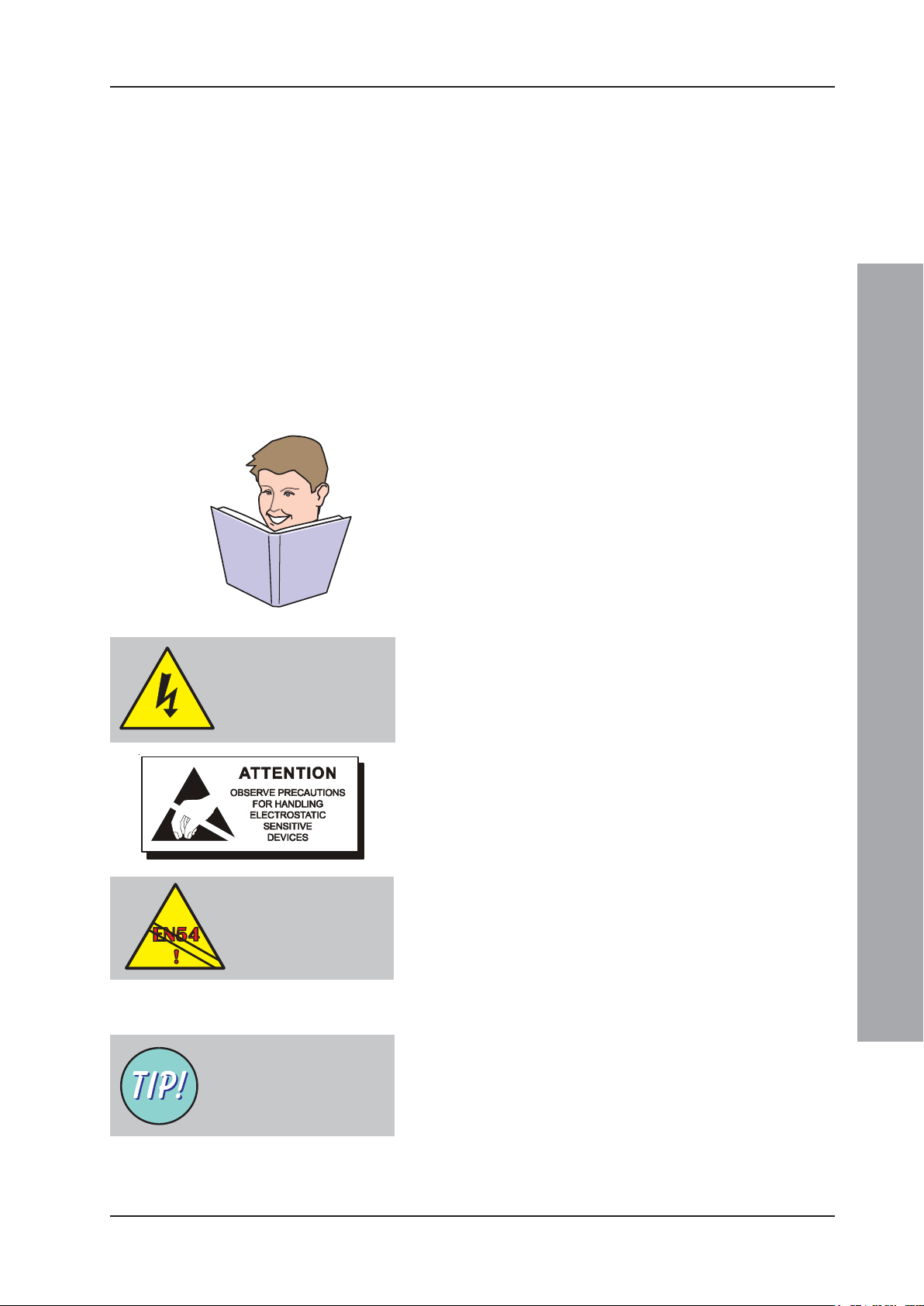
2.1.2 Warnings and Cautions
Where appropriate, this guide and the remainder of the
manual include advisory warnings and cautions to remind
you to consider safety at all times, especially when
following the procedures described in this manual.
You are alerted to any areas where high voltage [i.e. nonSafety Extra-low Voltage (SELV)] is present, or where
there may be a risk of damage to static-sensitive devices
if the recommended procedures described in this manual
are not followed. An example of a high voltage warning
and anti-static caution is provided to the left of this
paragraph.
The ID3000 Series control panel has many powerful builtin features which, if used inappropriately, may contravene
the requirements of EN54. Where there is a possibility
of such an occurence, a suitable warning is given with
brief details of the EN54 requirement. A typical EN54
non-compliance warning is illustrated at left.
Installation Guide
Magnetise the tip of your
screwdriver to help when
offering small screws to
holes in confined spaces.
2.1.3 Tips
‘Handy tips’ are included, where appropriate, to assist
you in following quick and safe procedures for fire
detection system installation and integration.
Look for the ‘TIP!’ icon and supporting text, typically
illustrated at left.
3 997-274-000-6, Issue 6
September 2009
ID3000 Series Installation & Commissioning Manual
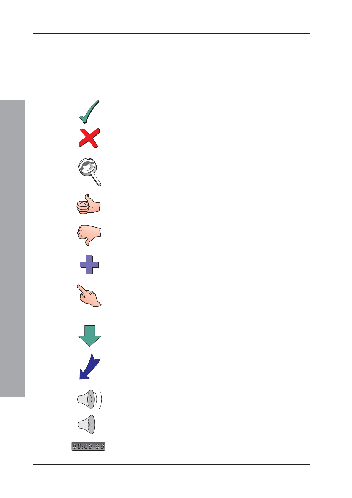
2.1.4 Glossary of Icons
Throughout this Installation and Commissioning Manual
and other supplied user documentation a number of
simple icons are used, either on their own or together
with larger illustrations, to simplify a particular task or
process.
The following icons are used to advise or indicate:
a. DO follow the recommended procedure or method
b. DO NOT use this procedure or method
c. Inspection of an item or sub-assembly is required at
this point
Installation Guide
d. Following a defined process meets the required
approval/inspection criteria or standards
e. Following a defined process does not meet the
required approval/inspection criteria or standards
f. Additional items to be considered
g. This icon placed next to a pushbutton requires you to
press it as part of a described process, such as isolate
or test, or while programming the panel. Where two or
more icons are used, a number may be placed on or
near each hand to indicate the order of selection: 1
coming before 2, etc.
h. Activity process step - flow arrow for single action or
iterative actions
i. Leader arrow - used with activity processes
September 2009
j. Sounder operating
k. Sounder not-operating or silenced
l. Digital clock timer - press and hold the applicable
pushbutton for the time indicated
4997-274-000-6, Issue 6

ID3000 Series Installation & Commissioning Manual
1.5m
2.2 Pre-installation Check List
Before installing the ID3000 equipment or fitting sensors,
you must first ensure that the following criteria have been
met. Failure to do this may not only result in damage to
the equipment, but may also cause problems when
commissioning the equipment or adversely affect its
performance.
2.2.1 Some DO’s and DON’T’s
Before selecting a location for the control panel and
devices, DO make sure that:
a. The operating ambient temperature is in the
recommended range:
5°C to 35°C and
b. The relative humidity is between:
5% and 95%
c. The panel is wall mounted in a position which allows
clear visibility of displays and easy access to operating
controls. The height above floor level should be chosen
such that the LCD is just above normal eye level
(approximately 1.5 metres)
d. DO NOT locate the panel where it is exposed to high
levels of moisture
Installation Guide
e. DO NOT locate the panel where there are high levels
of vibration or shock
5 997-274-000-6, Issue 6
September 2009

ID3000 Series Installation & Commissioning Manual
f. DO NOT site the panel where there would be
restricted access to the internal equipment and
cabling/wiring connections.
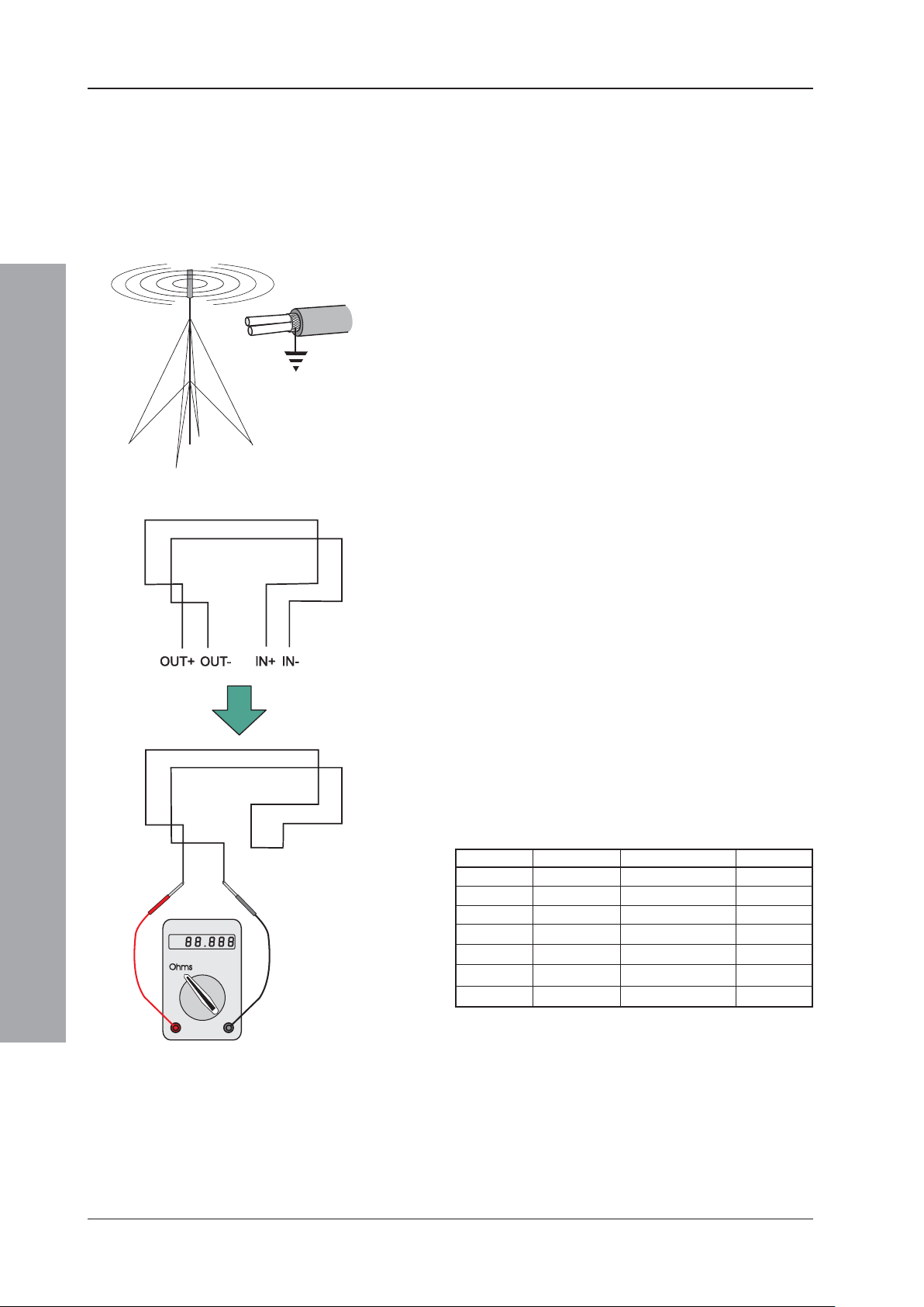
2.3 Transient Protection
This equipment contains transient-protection devices.
Although no system is completely immune from lightning
transients and interference, for these devices to function
correctly, and to reduce susceptibility, this equipment
must be earthed correctly.
As with all solid state devices, this system may operate
erratically or can be damaged if subjected to lightninginduced transients.
The use of overhead or outside aerial wiring is not
recommended due to the increased susceptibility to
nearby lightning strikes.
Installation Guide
September 2009
6997-274-000-6, Issue 6
ID3000 Series Installation & Commissioning Manual
1
2
To avoid damage to the
control panel ensure that
you follow these
instructions
2.4 Installation
The ID3000 Series of modular fire control panels are
relatively simple to install providing the recommended
procedures described in this Installation Guide are
followed.
Follow all installation instructions described in this
manual. These instructions must be understood and
the manufacturer’s recommendations followed to
avoid damage to the control panel and associated
equipment.
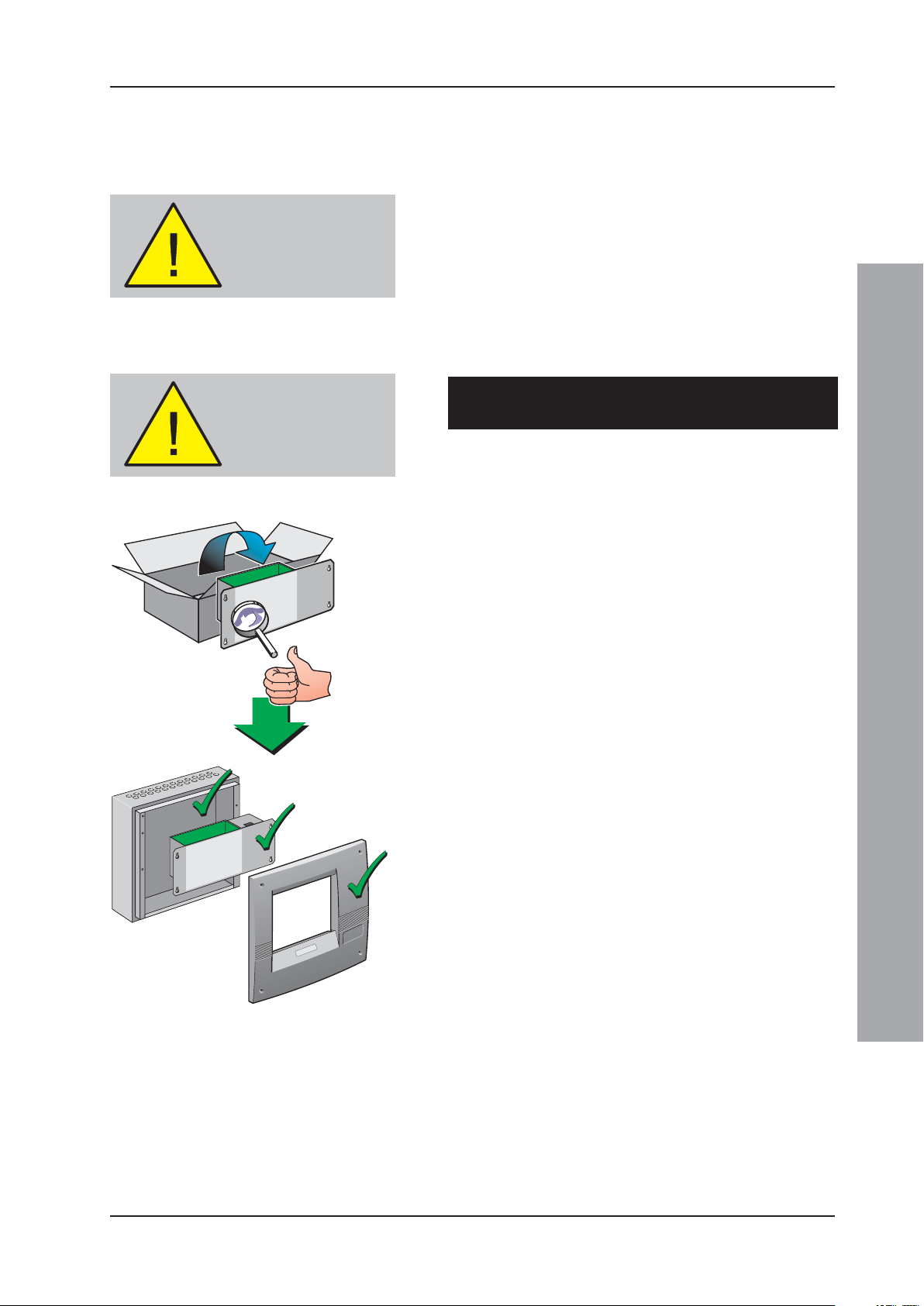
2.4.1 Checking Your Panel for Damage
Do a quality check
before proceeding with
the installation!
It is important to check all supplied equipment for
damage before proceeding with the installation!
Before attempting to install the modular components of
your ID3000 Series control panel, or other equipment,
you should do the following:
1 After removing the various control panel modules or
other related equipment from its packaging, and
before you proceed with installing it in its chosen
location, check for any damage that may have
occurred while in transit.
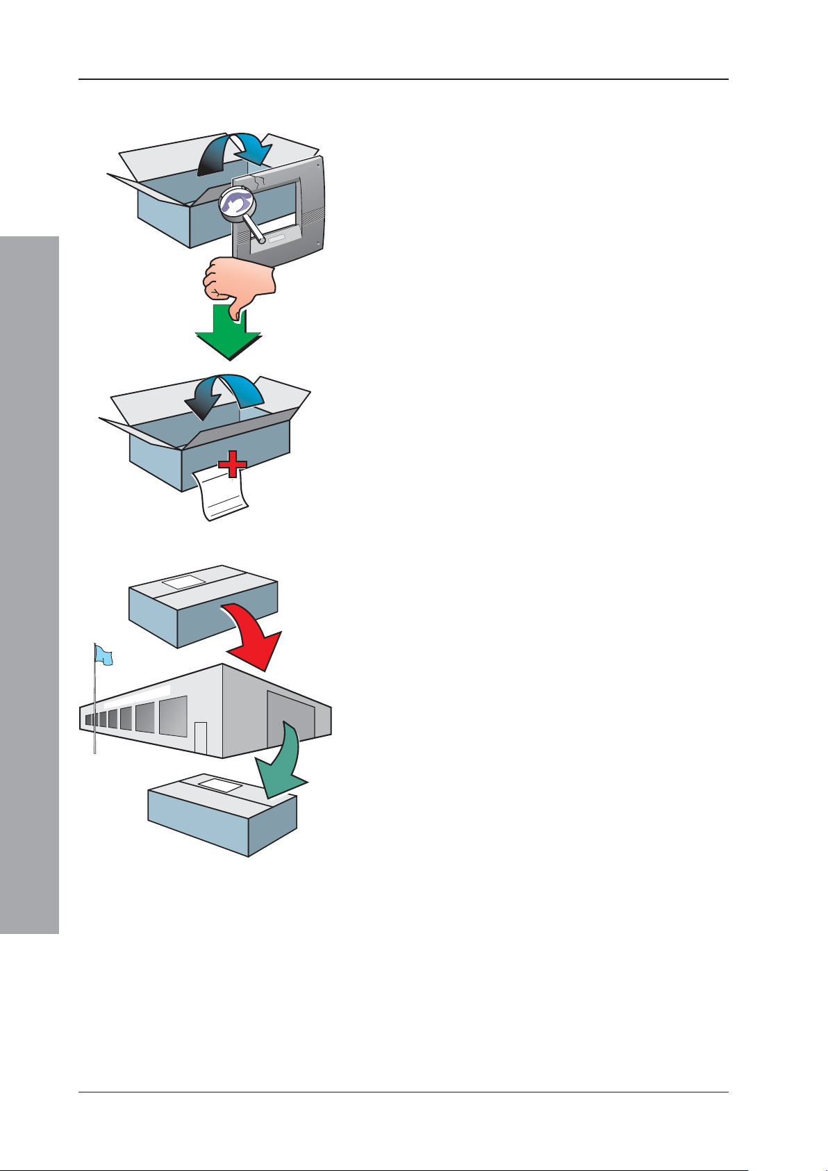
Note: In the unlikely event that any of the supplied ID3000
Series items has been damaged, you MUST NOT
fit it but return it to your supplier. The procedure
for returning faulty items is described in
Section 2.4.2, What to do if Your Module is
Damaged or Suspect.
2 If you are satisfied that none of the supplied items
has been damaged you can now proceed with the
installation procedure. This manual addresses the
recommended installation methods of the various
ID3000 Series equipment components which are
supplied as separate build modules. Refer to the
relevant sections that apply to your configuration
requirements.
Installation Guide
To prevent unnecessary damage to the electronic
components, the panel back box(es) should be installed
first, i.e. without fitting the main chassis at this stage.
Refer to Section 2.4.3, Back Box Fixing for details.
7 997-274-000-6, Issue 6
September 2009
ID3000 Series Installation & Commissioning Manual
Thhshj
iidjdhhh
Adfddd
jhjhgdjsfff
iiiiojh
yudjdfh
jfklrlkr
uuu
uui
hjfjufhf
jjjk
k,kljk
uu
ulg
efjkfjkjk
2.4.2 What to do if Your Module is Damaged or
Suspect
1
If you have problems regarding the quality of any supplied
order items including the control panel, its ancillaries or
this manual or items are missing, follow the procedure
below.
1 DO NOT continue with the installation but contact your
supplier for advice on what to do next.
Similarly, if the product is found to be faulty during
installation contact your supplier immediately.
2 To aid your supplier and the manufacturer, you are
requested to:
2
Thhshj iidjdhhh
Adfdddjhjhgdjsfff iiiiojh
yudjdfh jfklrlkruuu uui
hjfjufhfjjjk k,kljk uu ulg
efjkfjkjk
3
Installation Guide
a. Quote the manufacturer’s unique batch reference
number which can be found on the packaging, main
chassis or inside the back box
b. With reference to PCBs, quote the part number and
revision level which can be found along one edge of
the PCB - refer to the applicable section of this manual
for specific details.
c. Note all the details relevant to your complaint, date of
receipt, packaging condition, etc. and forward this to
your supplier.
3 Where the product needs to be returned to your
supplier, you are requested to use the original
packaging, or suitable anti-static equivalent, wherever
possible.
September 2009
8997-274-000-6, Issue 6
ID3000 Series Installation & Commissioning Manual
Continued overleaf.....
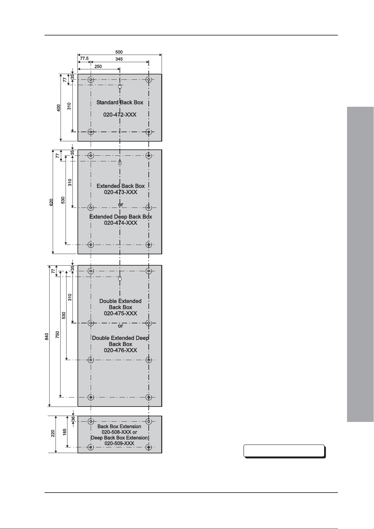
2.4.3 Back Box Fixing
The ID3000 Series control panel back boxes are available
122mm deep and 220mm (external dimensions including
fixing dimples). Where required, the deeper back boxes
allow the fitting of high-capacity-rated batteries as defined
in Section 7.5 Batteries and internally-mounted PSUs other
than the 3A-rated version. Where two part numbers are
quoted in the drawing at left, the first number refers to the
shallower back box and the second number refers to the
deeper back box.
The standard back box (PN: 020-472-XXX) is available
only in the 122 mm depth.
The fixing dimensions given below are applicable
irrespective of the back box depth.
Back Box Extension
In addition to the main back boxes, a smaller version, known
as a back box extension, is available. The back box
extension is also available in two depths: standard and deep.
The back box extension is designed to be wall mounted
immediately below any of the range of similar depth main
back boxes and is provided with corresponding 20mm
knockouts on the top and bottom faces. 20mm knockouts
are also provided on the top, bottom and rear faces of the
back box extension.
Wall Flatness
To prevent distortion, the ID3000 Series back box MUST
be installed on the wall as flat as possible, i.e. with a
maximum flatness deviation between any two points of
3mm. Where the wall is out of tolerance, use appropriate
packing pieces when installing the back box to meet the
above requirements.
Failure to comply with this requirement will result in
the misalignment of the internal and external screw
fixings.
Procedure
When a suitable location has been found for installing the
ID3000 Series control panel, proceed as follows:
1 Using the centrally-positioned keyhole to temporarily
hold the back box in the required position on the wall,
mark the position of the fixing holes while ensuring
the panel is level.
Installation Guide
Notes:
All dimensions are in millimetres.
Fixing hole diameters are 6mm.
Continued overleaf.....
9 997-274-000-6, Issue 6
September 2009
ID3000 Series Installation & Commissioning Manual
DO NOT use the back
box as a guide when
drilling.
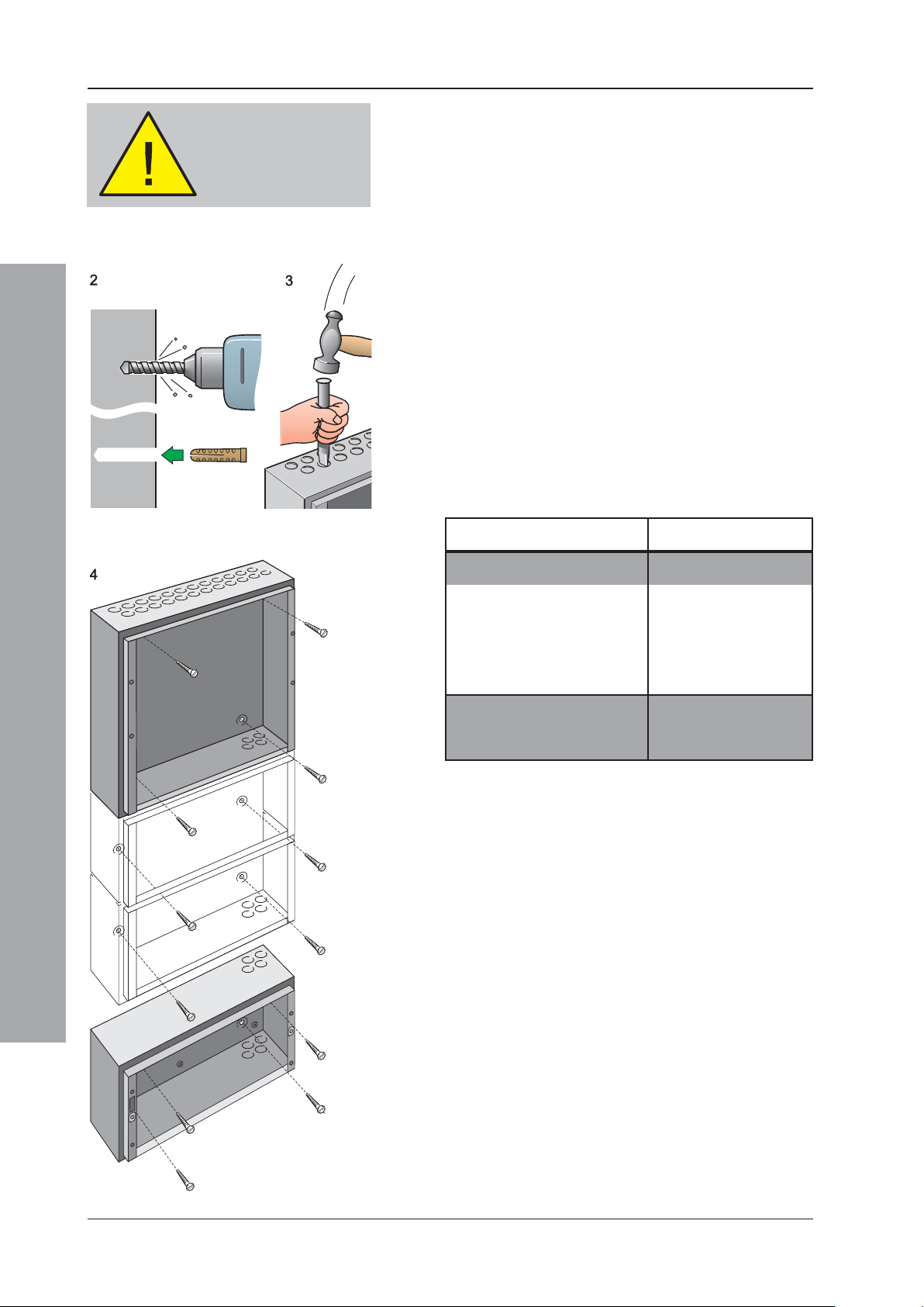
2 Using a suitable-sized drilling bit - for holes to take up
to 6mm (No.12-sized) wood screws - drill the required
number of holes.
3 Prepare apertures (20mm knockouts) required for
cable access.
4 Screw the panel back box to the wall using all fixing
holes and appropriate-sized screws. The back box
fixing holes can take up to 6mm (size No.12) roundor pan-headed screws (DO NOT use countersunk
screws).
Note: Make sure the screw in the keyhole is driven fully
into the recess to avoid impacting the main chassis
when this is being fitted.
The number of screws required depends on the size
of the back box. The recommended screw quantities
are as follows:
Installation Guide
Back Box Part Number Screw Quantity
020-472-XXX 4
020-473-XXX 6
020-474-XXX 6
020-475-XXX 8
020-476-XXX 8
020-508-XXX 4
020-509-XXX 4
September 2009
2.4.4 Electronics Modules
The ID3000 Series panel electronics modules, i.e. the
main chassis, which contains all processing, userinterface and input/output processing PCBs, and either
the Power Supply Unit (PSU) or Dual Transmission Path
(DTP) unit, are supplied as separate, self-contained
assemblies. These modules are fitted in the panel back
box once all site power distribution and fire detection loop
cabling has been provided, in accordance with the system
design requirements and applicable local standards.
10997-274-000-6, Issue 6
ID3000 Series Installation & Commissioning Manual
This procedure MUST be followed:
To avoid damage to the
electronics, remove trades’
operation debris before
fitting module.
Before drilling the back
box, make sure that no
equipment is fitted.
1 Fit the DTP or PSU to the main chassis - refer to the
appropriate sub-section of Section 5 for details.
2 Fit the main chassis to the back box - refer to Section 5.3
for details.
3 When individually checked for cable end earth faults,
make all wiring, cabling and battery connections (but
NOT the battery interlink) to the main chassis - refer
to Section 7, Commissioning for details.
2.5 Replacing the Electronics Modules
In the unlikely event that an electronics module becomes
faulty, all necessary instructions are provided with the
replacement item and in this manual under Section 5,
Panel Electronics Modules.
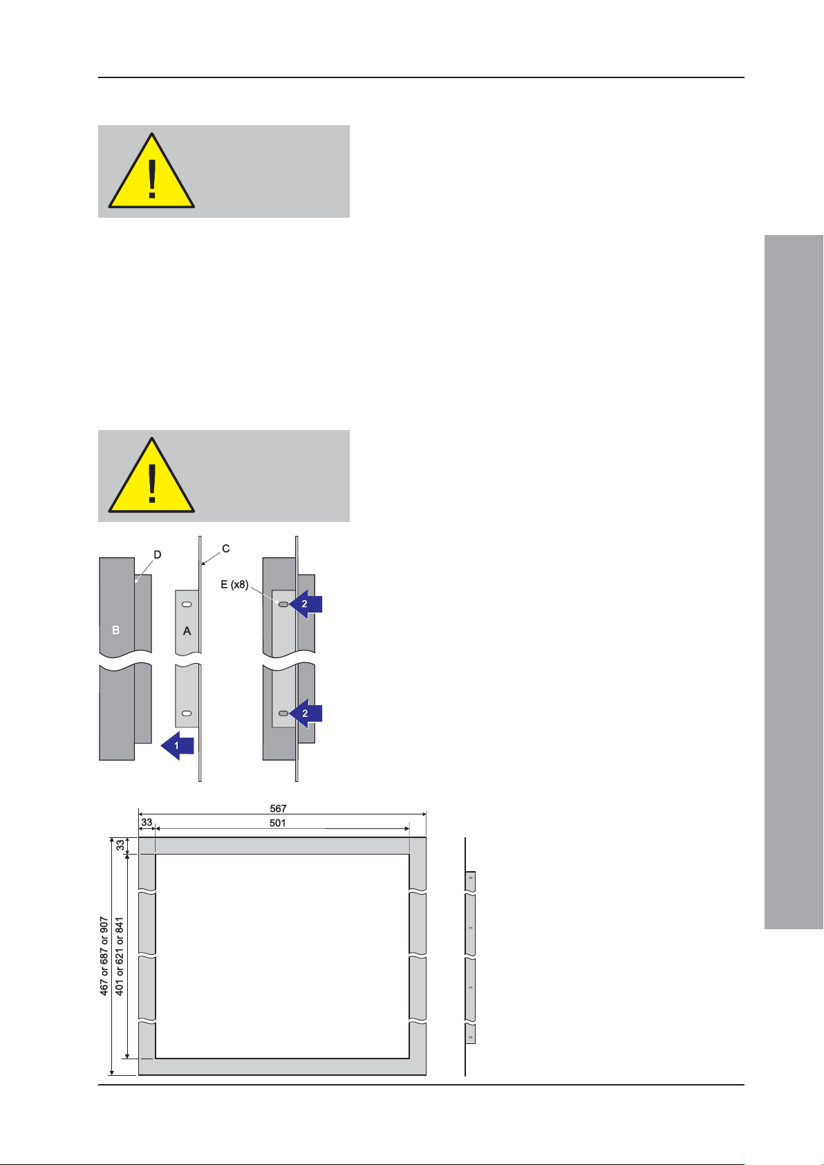
2.6 Flush Mounting Bezel (Optional)
If semi-flush mounting of the ID3000 Series control panel is
required, a recess 110mm deep, for the standard depth
versions, or 208mm, for the deep versions, and large enough
to accommodate the back box must be cut in the wall (refer
to Section 2.4.3 Back Box Fixing for dimensions).
To fit the bezel:
1 Offer the bezel (A), flat side towards you, to the front
of the back box (B) and position it so the bezel front
face (C) is lined up with the front face of the back box
shoulder (D).
2 With the bezel held in position, use the slotted holes
(E) on the bezel side plates as guides to drill eight
3mm holes. Remove any swarf created.
3 Use M3 self-tapping screws for fixing.
Note: The ID3000 Series back box must be fixed using
the rear fixing holes and reliance must not be
placed on the bezel as a means of fixing. The back
box must be fixed to a solid vertical surface, or
sub-frame inside the recess using the normal rearmounting holes.
Installation Guide
All dimensions in millimetres
11 997-274-000-6, Issue 6
September 2009
ID3000 Series Installation & Commissioning Manual
i
ii
C
D (x4)
View
a
or b
View
a
or b
View
a
or b
E (x2)
F
H (x2)
G (x2)
I (x2)
B (x4)
iii
View b
D (x4)
E
(x2)
H
(x2)
View a
D (x4)
E
(x2)
H
(x2)
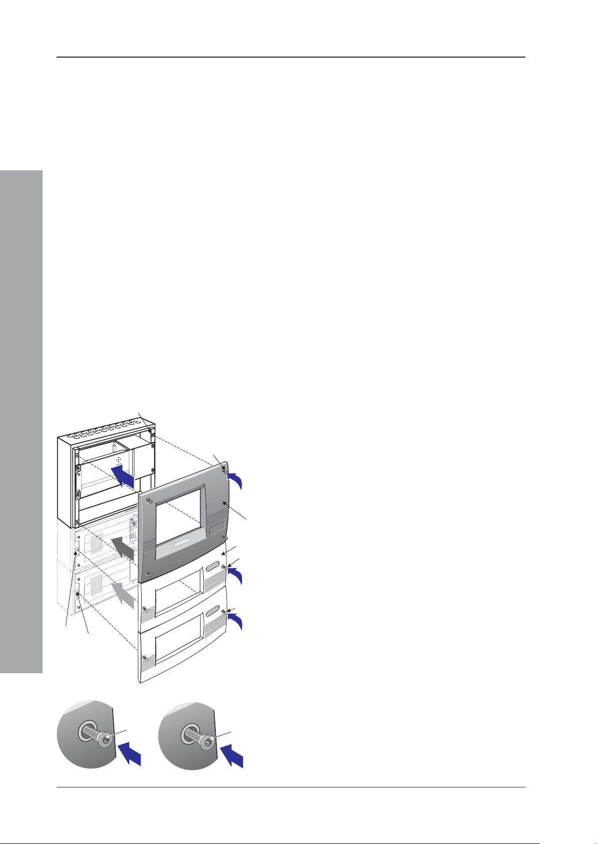
2.7 Moulded Front Covers
The ID3000 Series control panel is supplied with one, two
or three moulded front covers, depending upon your panel
configuration. Two moulded cover types are available; the
main and extension. All panel sizes require a main cover
kit (PN: 020-480). The larger panel sizes also require one
or two extension cover kits (PN: 020-481); the extended
versions use one extension cover and the double-extended
versions require two. The moulded front covers are also
available with high-security fasteners: main cover
(PN: 020-513); extension cover (PN: 020-514).
Note: Where the 256-Zone Status Indication kits are used,
only the main moulded cover is required as a dedicated
cover is provided with this option. Refer to Section 5.5.3.
Observe ALL safety and anti-static precautions when
fitting the covers.
User Interface Doors (Optional)
If required, any cover can be fitted with a lockable,
transparent User Interface Door. This must be done
BEFORE the moulded cover is fitted to the back box (refer
to the instructions supplied with the User Interface Door).
B (x4)
D (x4)
Installation Guide
G (x2)
I (x2)
View a
D (x4)
E (x2)
H (x2)
View b
View
aorb
E (x2)
View
aorb
H (x2)
View
aorb
D (x4)
E (x2)
H (x2)
Taking suitable precautions, remove all packaging and
inspect for any damage that may have occurred during
transit. If damage has occurred, DO NOT PROCEED,
contact your supplier and refer to Section 2.4.2. If no
damage is evident, fit the main cover as follows:
1 Offer the moulded front cover (C) symmetically to the
front of the back box in the correct orientation. The inner
top edge of the moulded front cover rests on the top flange
of the back box.
2 Two types of hexagonal socket-headed M6 screw (D)
are used to fasten the cover to the back box: a. the
standard version, or b. the high-security version. The
standard version is tightened by means of a 4mm
hexagonal socket key, while the high-security version
requires a special 4mm security tool (PN: 334-068).
The tool is supplied with the cover.
To remove the cover, use the appropriate tool to unscrew
the fasteners.
Note: Ensure the cover is supported when releasing the
last fastener!
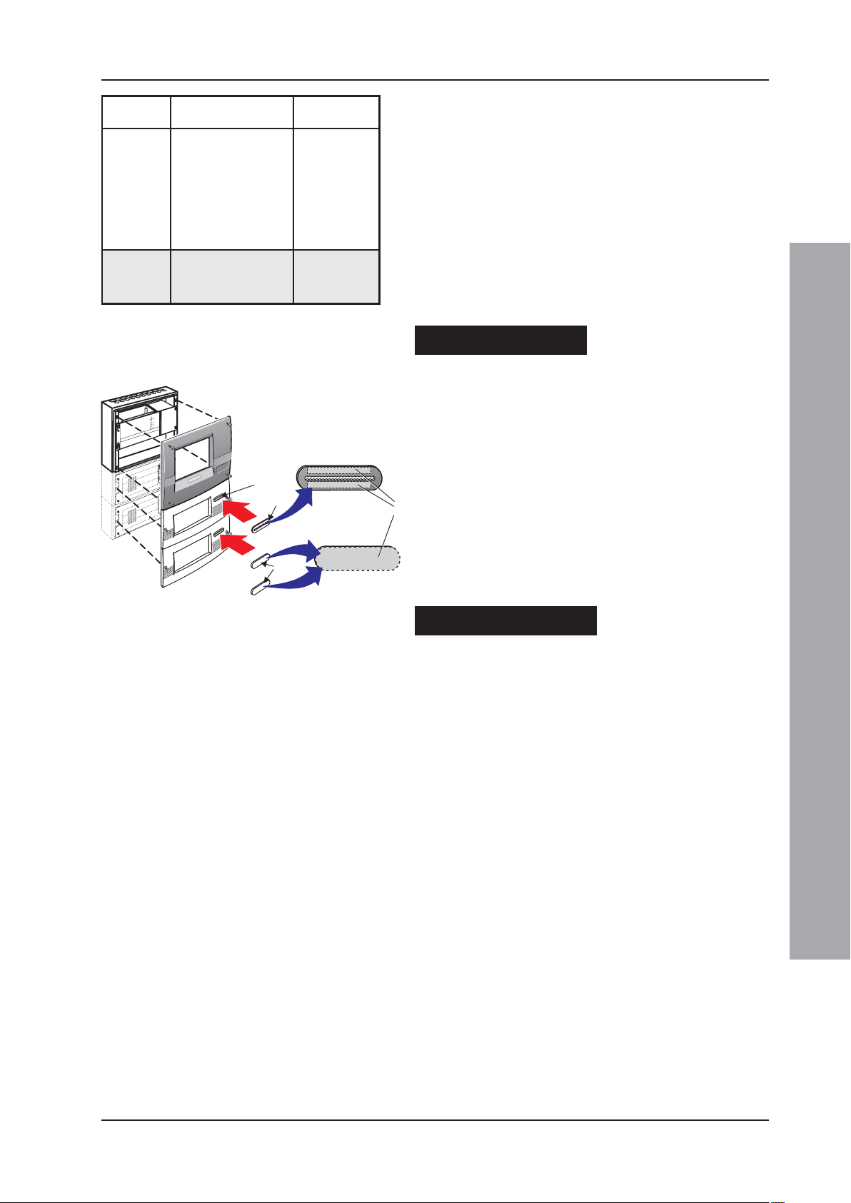
To fit the upper extension cover (F), follow the same
procedure as described for the main cover but with the
following differences:
1 There are only two M6 screws (E), which must be
inserted into their respective fixing locations (G). If a
PRN-ID printer is fitted, refer to step 2 below.
September 2009
12997-274-000-6, Issue 6
ID3000 Series Installation & Commissioning Manual
PN: 236-624
PN: 345-338
a
b
c
J
K
M
L
eziSlenaP
)mm(
ylbmessAxoBkcaB
rebmuN
forebmuNlatoT
srenetsaF
2 Prior to fitting the cover, if a printer is installed ensure
that you have allowed a sufficient length of printer
paper to be pulled through the cover aperture.
)i(004
)ii(026
)ii(026
)iii(048
)iii(048
XXX-274-020
XXX-374-020
XXX-474-020
XXX-574-020
XXX-674-020
4
6
6
8
8
3 Fit the appropriate plate over the printer paper exit
aperture.
The removal procedure for each extension cover is the
same as for the main cover.
The procedure for fitting the lower extension cover is the
xoBkcaB
:snoisnetxE
XXX-805-020
XXX-905-020
2
2
same as that for the upper extension cover, using two M6
screws (H) and the lowest set of fixing locations (I). The
removal procedure is the same as for above.
If a printer is fitted ....
Use the metal serrated plate with the aperture (J),
provided, and fix over the extension cover recess (K).
Fit the serrated plate to the extension cover as follows:
1 Remove the protective paper strips (L) from the back
PN: 236-624
face of the plate to reveal the adhesive areas.
2 Offer the serrated plate horizontally to the extension
cover and, using sufficient pressure only, fix in the
recess (K).
PN: 345-338
3 Using scissors, cut the end of the printer paper to
produce a straight edge and insert it through the
serrated plate aperture BEFORE fitting the extension
cover.
If a printer is not fitted ....
When fitting any extension cover without a printer use
the blanking label, i.e. with no aperture, (M) provided.
Follow the procedure given above to fix it over the
extension cover printer paper exit aperture (K).
Installation Guide
13 997-274-000-6, Issue 6
September 2009

ID3000 Series Installation & Commissioning Manual
WARNING Risk of electric
shock. Before working on
mains connections, ensure
mains power supply to the
panel is disconnected.
Installation - Cabling
3 Cabling
3.1 Cabling Instructions
All wiring should comply with current IEE wiring
regulations (BS7671) or the applicable local wiring
regulations. Note also the requirements of EN54-14 for
cabling and interconnection of a fire detection and alarm
system.
For information on wiring inputs and outputs refer to the
appropriate module cable and wiring instructions to
identify terminals. Refer also to Section 7.4
Commissioning, External Wiring for details.
Use the following rules when installing cables:
1 Cables should be brought into the cabinet through
the 20mm knockouts provided on the top or top-back
face of the back box. Ensure that all openings in the
back box are closed before connecting power to the
panel. For example, if more knockouts than required
have been removed, then block the holes with
blanking glands. This is to prevent access to
hazardous voltages.
2 Tails should be of sufficient length to connect to the
appropriate termination points at the commissioning
stage.
3 Cables should be screened and should be terminated
in appropriate glands to meet local wiring codes and
to preserve the integrity of the screen connection. The
cable screen is to be clamped inside the cable gland,
which must be fitted to ensure a 360o bond is formed
with the metal of the back box.
4 The supply to the panel must be provided with a
suitable and readily accessible double-pole mains
disconnect device. The mains supply must be suitably
fused and rated according to the specifications (see
Appendix 2, Specifications).
5 The knockouts on the extreme right-hand side and
those provided on the bottom of the back box should
be used for mains cable entry. DO NOT bring mains
cables in through any other knockout holes and
ensure that the mains wiring is always separated from
the low voltage wiring. Tails of mains cables should
be provided with suitable additional sleeving before
connecting to the mains terminal block.
6 All low voltage cables should have a minimum 300Vac
rating.
General cable installation notes are given in Section 3.2,
Cable Installation Notes.
September 2009
Earth Blade Connections
Note: All blade connections to earth incorporate a locking
barb. To remove this connection, pull the shroud,
NOT the earth wire.
14997-274-000-6, Issue 6
ID3000 Series Installation & Commissioning Manual
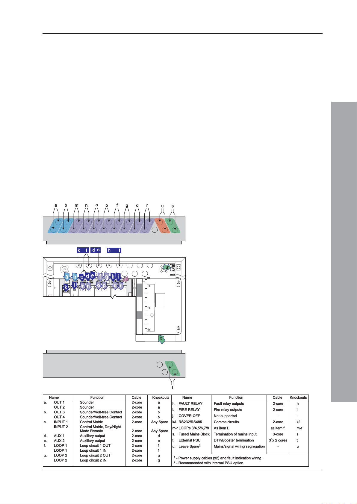
3.1.1 Cable Terminations
This section provides guidance on where to bring cables
into the back box for ease of termination. Ensure the
following requirements are met:
a. If the power supply unit (PSU) is mounted in the back
box, the mains supply should be brought into the
control panel such that the cable path to the mains
termination block is kept as short as possible.
b. If the PSU is mounted externally to the panel, the dual-
supply power cables and appropriate fault condition
wiring should be brought into the panel using the
bottom face’s knockouts (as indicated). Refer to
Section 5.3 Dual Transmission Path/Booster
Module for termination details.
c. All loop and ancillary cable terminations should be
brought into the panel at suitable positions to ensure
tails are kept as short as possible.
d. A row of knockouts, ‘u’, should be left to provide
adequate mains supply input/signal cable segregation.
The drawing shows the recommended points
of entry so that cabling can meet these
requirements.
Panel with internal PSU
i. Base PCB cabling/wiring terminations
using top-face knockouts ‘a, b, f and g’.
ii. Base PCB cabling/wiring terminations
using rear knockouts ‘d, e, h and i’.
iii. RS232 or RS485 cabling terminations using
rear knockouts ‘k and l’.
iv. Loops 3/4, 5/6, 7/8 cabling using top face
knockouts ‘m/n, o/p and q/r’ respectively.
v. Power supply cable entry using knockouts ‘s’.
Panel with external PSU
As above except for item v above, which is
replaced with:
vi. DTP/Booster Module cabling using
knockouts ‘t’. See external PSU and DTP/
Booster Module instructions for details.
Installation - Cabling
15
997-274-000-6, Issue 6
September 2009
ID3000 Series Installation & Commissioning Manual
3.2 Cable Installation Notes
3.2.1 Introduction
The following notes are intended to assist installers of
analogue addressable control systems. They have been
produced from information derived from the supplier's
technical resource and from information fed back
concerning existing systems.
3.2.2 Quality of Cable and of Cable Installation
It is vitally important that good quality cable is used, and
that correct installation techniques are followed. In general,
the following cable installation requirements must be met:
a. All cable sections must be circular to allow effective
cable clamping using the cable glands.
b. The cable must be screened (sheathed) to provide
protection against Radio Frequency Interference (RFI) and
the screen must be connected to earth at the control panel.
c. Multiple earthing of the screen should be avoided.
NOTIFIER’s field products use insulated mounting bases
and back boxes to achieve this. We recommend that
this practice be continued if other connections are made.
To achieve this with MICC cable may require the use
of insulated cable glands at one end of the cable.
d. The screen must be continuous throughout the loop.
e. The maximum resistance of the loop should not exceed
the limits defined in Section 7.4.2 Loop Checks
before Connecting Wiring, step 2. To check this,
measure between IN- and OUT-, multiply the result by
2 and add the resistance of each isolator (range 0.1 to
0.13 ohms each). The cable capacitance should be less
than 0.5μF. Typically this will allow a maximum loop length
of 2000m of screened 1.5mm2 cable. Cable recommended
for use is MICC with a LSF PVC overcovering, a fire
resilient cable to BS7629 or PVC/SWA/PVC to BS6387.
Installation - Cabling
September 2009
Recommended Cables:
Manufacturer Product Name Part Number Type
AEI MICC 2L1.5 Enhanced
AEI Firetech 298-052 Standard
Draka FiretufPlus FTPLUS2E1.5RD Enhanced
Draka Firetuf FTZ2E1.5 Standard
Prysmian FP Plu s FP Plus 2x1.5 Red Enhanced
Prysmian FP200 Gold FP200 Gold 2x1.5 Red Standard
Arrow - 7-2-4S Not rated
1
For a definition of ‘Standard’ and ‘Enhanced’ cable requirements and their different
applications, refer to BS 5839-1 Section 26. Enhanced cable is typically required
for spur sounder outputs, while standard cables may be adequate for other firerelated I/O provided there is diverse cable routing. The multi-core cable from Arrow
is suitable for RS232 connections to a printer.
1
f. We recommend that the system should be wired in 2-core
cables and each 2-core cable should be specific to one
function.
g. The RS485 communication cable used should be rated
as suitable for up to 200mA in a short circuit condition.
16997-274-000-6, Issue 6
ID3000 Series Installation & Commissioning Manual
3.3 EMC Considerations
Following the above instructions and by using suitable
cables EMC problems will be avoided. In particularly
difficult EMC environments, or where non-preferred cabling
is used, it is possible to fit additional ferrite suppressors
(sleeves) to cables entering the control panel.
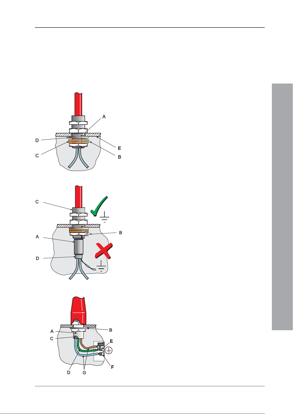
3.3.1 Screen Termination
Use the following method to terminate the cable screens:
Use a metal gland with slots (A) that allow the drain
wire or screen (B) to be clamped between flat washers
(C). Use a steel locking washer (D) between the brass
washers and the internal surface of the back box (E).
This will provide the best EMC termination. Suitable
glands are the CTX range available from CMP UK Ltd.
The part chosen should fit the 20mm knockouts.
3.3.2 Ferrite Sleeves (Optional)
Ferrite sleeves are not normally required with the ID3000
Series control panel. In difficult EMC environments, or
where non-preferred cables are used, optional ferrite
sleeves should be fitted to both the loop and sounder
wiring. The ferrite sleeves (A) are to be fitted over the
conductor(s) of each cable - and NOT over the screen of
the cable, which should pass outside of the sleeve. They
should be fitted as close as possible to the entry point of
the cable, i.e. as near as possible to the screen termination
(B) to the metal cable gland (C). The sleeve should be
held in place using a cable tie (D).
The ferrite sleeves are available for purchase from
NOTIFIER’s distributors (quote Part No. 538-143).
3.4 MICC Cables
MICC cables must be fitted with metal cable glands (A) use Type A2 glands. Use a steel locking washer (B) to
ensure good earthing continuity and correct termination
of the gland. In particular, the mains cable requires that
the cable gland (A) is fitted with an earth tail kit (C). The
earth tail kit must be connected, using an insulated wire
(D), to the panel safety earth connection (E) at the mains
termination block (F). The bare mains wiring from the MICC
cable must be suitably-insulated (G) and terminated in
accordance with appropriate local wiring regulations.
Installation - Cabling
17
997-274-000-6, Issue 6
September 2009
ID3000 Series Installation & Commissioning Manual
4 Sensors and Modules
Each of these devices is packaged with an instruction
leaflet showing the correct interconnections for various
applications.
4.1 EN54 Requirements
The ID3000 Series Control Panel design allows for the
connection of up to 198 loop devices per analogue loop;
i.e. up to 99 sensors and 99 modules.
4.1.1 Loop Devices - Sensors and MCPs
EN54-2: 13.7
Without E-LIBs -
Maximum of 512
Sensors and/or
MCPs per system.
EN54-2: 13.7
With mix of LIBs and
E-LIBs - Maximum of
512 Sensors and/or
MCPs not connected
to E-LIBs.
EN54-2: 12.5.2
Maximum of 32
Sensors and/or MCPs
between isolators.
If Enhanced Loop Interface Boards (E-LIBs) are not fitted,
then to comply with the requirements of EN54-2, a
maximum of 512 sensors and/or MCPs should be
connected to the control panel across ALL analogue
loops, including all conventional zone detectors and/or
MCPs connected.
If E-LIBs (PN: 124-292) are fitted, the design limits given
above in Section 4.1 apply. If a mixture of E-LIBs and
LIBs (PN: 124-323) are fitted, then the restrictions of the
first paragraph of Section 4.1.1 apply to all loops not
connected to E-LIBs.
Failure to comply contravenes the requirements of
EN54-2 in the event of a system fault.
4.1.2 Loop Devices - Isolators
Isolators must be used on each analogue loop to separate
sensors and/or MCPs, including all loops with
conventional zone detectors and/or MCPs connected.
To comply with the requirements of EN54-2, isolators
should be fitted between a maximum of 32 loop devices.
For the ID3000 Series, do not place more than 25 loop
devices between isolators (20 if FET isolators are used).
Failure to comply contravenes the requirements of
EN54-2 in the event of a transmission path fault.
4.2 Loop Wiring Testing
Installation - Sensors and Modules
NEVER use a high
voltage tester on
the loop.
September 2009
Before connecting the panel or devices, the wiring of each
loop may be tested for continuity and insulation. Once
any components are connected, inluding isolators, no
high-voltage testers such as Meggers may be used on
the loop; low-voltage testers such as multimeters may
be used.
Note: If isolators are fitted, the +ve conductor of the loop
will be open circuit.
18997-274-000-6, Issue 6

ID3000 Series Installation & Commissioning Manual
To avoid damage to the
electronics, remove trades’
operation debris before
fitting module.
5 Panel Electronics Modules
5.1 Introduction
This section describes how to install the ID3000 Series
panel electronics, i.e. the Power Supply Unit (PSU) and
the main chassis, which contains all processing PCBs
and the optional PRN-ID printer.
DO NOT install the electronics module(s) until the building
is clear of trades’ operations. Before commencing the
installation, remove any debris, etc. which may have
accumulated in the panel back box.
Instructions are included for the following:
a. Installing either a Dual Transmission Path (DTP) unit/
Booster Module or a Kit PSU3A in the main chassis.
The DTP/Booster Module is designed for use with
PSUs other than the PSU3A unit (separate instruction
sheets are provided with these alternative PSUs). For
the Kit PSU3A, refer to Section 5.2. For the DTP/
Booster Module, refer to Section 5.3.
Note: For details of installing the PSU7A kit (PN: 020-
579) refer to separate instructions provided with the
kit.
b. Installing the main chassis plus DTP or Kit PSU3A in
the back box. Refer to Section 5.4.
c. Fitting a paper roll to the optional PRN-ID printer.
d. Zonal LED kit options.
Installation - Panel Electronics
19
997-274-000-6, Issue 6
September 2009
ID3000 Series Installation & Commissioning Manual
5.2 Kit PSU3A
The Kit PSU3A module is very easy to fit to the main
chassis, providing the instructions described below are
followed. The PSU is located in an open, rear
compartment of the main chassis and MUST be fitted
before installing the main chassis in the back box. The
PSU3A module is secured to the main chassis using four
M4 x 8 SEM screws.
Note: To replace a PSU3A, disconnect the batteries and
isolate mains power, reverse the installation
procedure to remove the faulty unit, then install
the replacement as described below.
Check Your Equipment....
Before proceeding with the PSU installation, first remove
all packaging and inspect for any damage which may
have occurred in transit. If no damage is evident, proceed
with the installation of the PSU module.
A Cautionary Note....
During this procedure, various wiring connections are
made and it is important that the manufacturer’s
recommendations are followed to avoid the possibility of
damage occuring when fitting the PSU module.
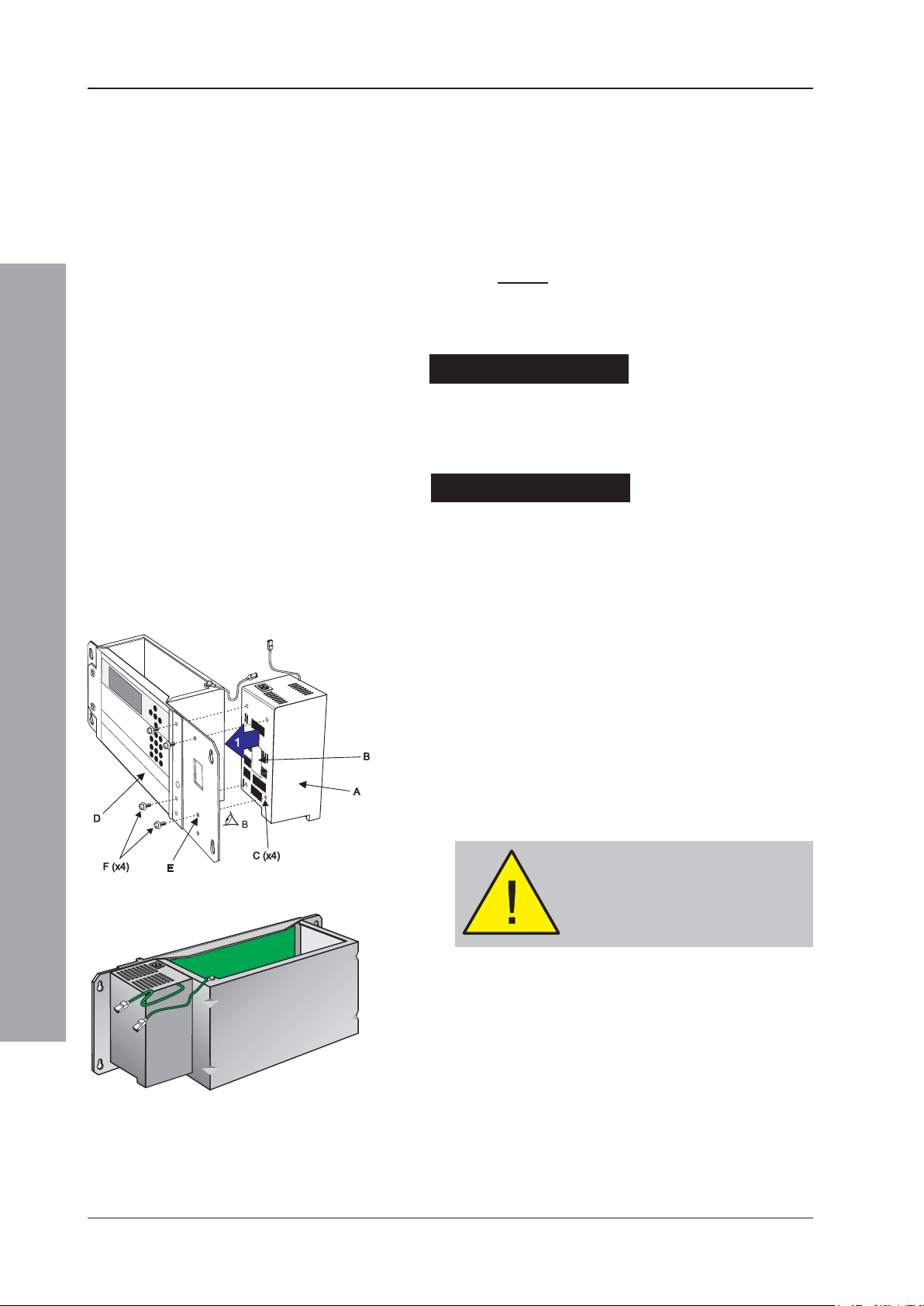
5.2.1 Procedure
Orientate the PSU3A assembly (A) so that the side with
the ‘rating’ label (B) is facing you (see drawing at left) this side is provided with four holes (C) for fitting the
PSU. Fit the PSU to the main chassis assembly (D) as
follows:
1 Line the four holes (E) on the front face of the main
chassis with the corresponding holes (C) on the PSU
assembly.
2 Use a No. 2 Posidriv screwdriver and the four M4 x 8
SEM screws (F) supplied with the PSU to secure the
PSU firmly to the main chassis.
Installation - Panel Electronics
CAUTION
When fitting the PSU, use only the
M4 x 8 screws supplied with the PSU
- and NOT the M4 x 16 screws
supplied with the Main Chassis.
September 2009
The drawing at left shows the PSU3A module correctly
located in the main chassis.
20997-274-000-6, Issue 6

ID3000 Series Installation & Commissioning Manual
G
3
I
J
G
H
4
5
H GL
K
M
H
5.2.1.1 Main Chassis Wiring Connections
3 Connect the 10-way ribbon cable (G) and the power
cable (H) to the PSU3A. The power cable connects
at two positions, as shown.
+ -
TEMPSNSR
'A'
A
4 Ease the connectors of these cables and the ferrite
through the aperture (I) in the main chassis. Pull the
cables through, taking up any slack.
'B'
5 With a sufficient length of each cable pulled through
to connect to the Base PCB, ease the grommet (J) in
to the aperture (I) and then slide it and the cables
sideways into the circular part until secure.
6 Terminate the cables on the Base PCB - the 10-way
ribbon cable (G) at socket SK8 (K) and the power
cable (H) at socket SK12 (L). Ensure the ferrite is
clear of all circuit boards.
Note: Connector (M) may not be fitted.
7 Fit the chassis into the back box (Section 5.4).
Installation - Panel Electronics
21
997-274-000-6, Issue 6
September 2009

ID3000 Series Installation & Commissioning Manual
1
2
230 VAC,
50
Hz
A
B
D
CH
G
F
E
N
L
MF: 5A (T) 250V HRC
L
N
230V (a.c.), 5A
WARNING!
Isolate mains power
before proceeding.
When terminating mains
leads, ensure that the
earth lead is longer than L
and N.
5.2.1.2 Mains and Safety Earth Wiring Connections
WARNING: Before proceeding, refer to the cabling
instructions given in Section 3.1. Isolate
mains power. Note that fuse information is
given in Appendix 1 Section 1.2.
TRANSIT CABLE CLIP: Before proceeding,
CAREFULLY cut the cable clip that secures the ferrite
cable loop to the front of the back box. DO NOT cut the
cable clip that secures the mains cable to the side of the
back box.
The 230V ac mains input wiring (A) must be terminated
at the fused mains termination block (B), located in the
top right-hand corner of the ID3000 Series back box (C).
The PSU mains cable (D) is factory-fitted to the
termination block. Push the mains cable’s connector (E)
into the socket at the top of the PSU3A. Pull tight the
cable clip at the side of the back box.
'X'
230 VAC,
50 Hz
MF: 5A (T) 250V HRC
VIEW
X
230V (a.c.), 5A
The safety earth is provided via a short factory-fitted lead
(F) from the mains termination block to a blade connector
at the right rear corner of the back box roof. All blade
connections to earth incorporate a locking barb. To make
a connection push the shrouded receptacle on to the earth
blade (1). To remove this connection, pull the shroud (2),
Installation - Panel Electronics
NOT the earth wire.
Using the wiring provided, make the following two earth
connections:
a. Between the PSU top plate and the back box (G).
b. Between the main chassis and the back box (H).
September 2009
Connection to the batteries is made using the supplied
battery leads, which may have to be cut to the correct length.
Connection of the batteries (and thermistor) is made at a
four-way socket mounted close to the bottom of the PSU
assembly. Access is gained from underneath the PSU once
the main chassis is fitted to the back box.
For more information on connecting the batteries refer
to Section 7.5, Batteries.
22997-274-000-6, Issue 6

ID3000 Series Installation & Commissioning Manual
5.3 Dual Transmission Path/Booster Module
The Dual Transmission Path (DTP)/Booster module is very
easy to fit to the main chassis, providing the instructions
described below are followed. The DTP/Booster module is
located in an open, rear compartment of the main chassis and
MUST be fitted before installing the main chassis in the back
box. The DTP/Booster module is secured to the main chassis
using four M4 x 8 SEM screws. A 4-wire cable supplied with
the module for backward compatibility is not required and should
be discarded.
Check Your Equipment....
Before proceeding with the DTP/Booster installation, first
remove all packaging and inspect for any damage which may
have occurred in transit. If no damage is evident, proceed with
the installation of the DTP/Booster module.
A Cautionary Note....
During this procedure, various wiring connections are made
and it is important that the manufacturer’s recommendations
are followed to avoid the possibility of damage occuring
when fitting the PSU DTP/Booster module.
5.3.1 Procedure
Place the DTP/Booster module (A) on a clean work
surface so that the side with the ‘rating’ label (B) is
uppermost (see drawing at left) - this side is provided
with four holes (C) for fitting the module. With the module
temporarily supported in this position, fit the main chassis
assembly (D) as follows:
Note: If the PSU is located in the back box, perform ‘Other
Wiring Connections’ step ‘a’ at the DTP/Booster
module end of the connection NOW. Access to the
ribbon cable connector becomes more difficult after
the module is fitted to the main chassis.
1 With the main chassis orientated with the front door
uppermost, carefully lower it until the part to the right
of the front door hinge rests on the DTP/Booster
module.
2 Line the four holes (E) on the front face of the main
chassis with the corresponding holes (C) on the
module.
3 Taking care not to trap the module’s cables and the
earth wiring, insert the four M4 x 8 SEM screws (F)
and, using a No.2 Posidriv screwdriver, tighten them
until the module is secured firmly to the main chassis.
With the module now secured, take the module’s two
cables into the main chassis’ PCB enclosure as follows:
4 First, ease the connector of the 10-way ribbon cable
(G) and the connector of the power cable (H) through
the aperture (I) in the main chassis. Pull the cables
through, taking up any slack.
5 Secondly, with a sufficient length of each cable pulled
through, to connect to the Base PCB, ease the
grommet (J) in to the aperture (I) and then slide it and
the cables sideways into the circular part until secure.
23
997-274-000-6, Issue 6
September 2009
Installation - Panel Electronics

ID3000 Series Installation & Commissioning Manual
A
C
D
B
E
The illustration at left shows the DTP/Booster module
correctly located in the main chassis.
5.3.1.1 Main Chassis Wiring Connections
Once the DTP/Booster module is fitted to the main
chassis, the two wiring assemblies that are held by the
grommet should now be terminated on the Base PCB
connection sockets as follows:
a. The 10-way ribbon cable (A) is to be terminated at
socket SK8 (B).
b. The 4-wire power cable (C) is to be terminated at
socket SK12 (D).
Note: Connector (E) may not be fitted.
5.3.1.2 Other Wiring Connections
CAUTION: Before proceeding, refer to the cabling
instructions given in Section 3.1.
The following additional wiring must be connected:
a. If the DTP/Booster module is to be connected to an
internally-mounted PSU (other than the Kit PSU3A), fit
the supplied ribbon cable between the DTP/Booster
connector (E) and the PSU’s LED status indication output
connector. This connection is not used if the PSU is
Main chassis
wiring -
pre-wired
(see above)
Installation - Panel Electronics
mounted externally.
b. Connect a suitable cable (supplied with the PSU)
between the PSU Charger Inhibit connector (F) and the
equivalent connector on the PSU (on PSU assemblies
PN: 124-190 and 124-190-001, this connector is labelled
ALARM). Connect + to + and - to -.
c. If the DTP/Booster module is to be connected to an
externally-mounted PSU, connect a suitable cable
between the COMMON FAULT connector (G) and the
Normally Open and Common connections of the
equivalent connector on the PSU.
d. Connect suitable (high-current) cables (if PSU is
internal, use cables supplied with the PSU) between
the Power connector (H) and the power supply unit.
Connect + to + and - to - (may be labelled 0V).
e. CAUTION! If using an externally-mounted PSU, it
is essential that an electrical safety earth
connection is made to the back box of the ID3000
panel. This connection should be routed with the other
PSU cables from the external battery box.
24997-274-000-6, Issue 6
September 2009

ID3000 Series Installation & Commissioning Manual
A
E (x4)
F (x4)
B/C
D
G (x4)
3
3
H I
4
4
J
5.4 Main Chassis
The ID3000 Series control panel main chassis provides
DO NOT fit the main
chassis in the back box
until the PSU and/or DTP/
Booster Module has been
fitted!
the following features:
a. System control and monitoring function PCBs
b. User-interface controls and system status indicators,
c. Space provision for three loop-interface PCBs, panel
networking and interface hardware for external
equipment using serial communications.
The main chassis is simple to fit in the back box providing
these instructions are followed.
5.4.1 Main Chassis Configurations
Alternative PSU output ratings and mains standby battery
backup periods can be supported using different main chassis
options. Consequently, the main chassis can be fitted with:
a. The Kit PSU3A, or a
b. DTP/Booster Module for use with PSUs other than
the Kit PSU3A, which can be installed behind the main
chassis in a deep back box or in a separate 78Ah
battery enclosure (refer to separate installation
F (x4)
E (x4)
G (x4)
5.4.2 Procedure
instructions provided with enclosure).
DO NOT fit the main chassis in the back box until the
PSU or DTP/Booster Module is in place (refer to
Section 5.2, Kit PSU3A or Section 5.3 DTP/Booster
Module).
Taking suitable anti-static precautions, such as wearing a
suitably-grounded wrist strap, remove all packaging from the
main chassis and ensure that it has not been damaged in
transit before proceeding any further. If no damage is evident,
and with the back box (A) secured to the wall in its chosen
location, ensure that either the Kit PSU3A (B) or DTP/Booster
Module (C) is fitted, then fit the main chassis (D) as follows:
1 Locate the four supplied M4 x 16 SEM screws (E) in
the back box holes (F).
2 Drive the four screws (E) in approximately half their length.
3 Taking suitable anti-static precautions, ensure the
main chassis is correctly orientated and offer the four
Installation - Panel Electronics
slotted holes (G) and locate on the threaded part of
the top two of the four screws (E) to avoid twisting the
chassis when securing in position.
4 Once the main chassis has been located on the SEM
screws (E) use a cross-headed screwdriver to tighten them.
5 Connect the earth lead (H) between the Kit PSU3A top
plate or DTP/Booster module and the earthing blade
terminals adjacent to the mains termination block (not
shown) in the back box. (See also step 5.2.1.2).
6 Connect the earth lead (I) between the main chassis earth
blade terminals and the earthing blade terminals adjacent to
the mains termination block (not shown) in the back box.
Note: The power supply ratings label is visable through
the aperture (J) in the main chassis.
25
997-274-000-6, Issue 6
September 2009

ID3000 Series Installation & Commissioning Manual
Up to 128 Zones plus
PRN-ID Printer
5.5 Zonal LED & Printer Options
The section describes the procedures for fitting zonal
LED modules and the integral PRN-ID printer. One or
two extension chassis are required to provide the zonal
LEDs required with or without the integral printer. The
following options are described in this section:
a. LEDs for up to 64 Zones. For panels with up to 64
zonal LEDs follow the instructions in Section 5.5.1.
b. LEDs for up to 128 Zones (as ‘LEDs for up to 64
zones’ x2, with a double-extended back box).
c. Fitting the PRN-ID Printer. The integral PRN-ID printer
can only be fitted with the extended or double-extended
back boxes. An extension chassis is required, either with
zonal LEDs 1-64 or with a blank fascia if these zonal LEDs
are not required. Refer to Section 5.5.2.
d. LEDs for up to 256 Zones. For panels with up to 256
zonal LEDs refer to Section 5.5.3. For this option the doubleextended back box and 256 Zone LED Kit is required.
Note: All fitting instructions assume that the correct back
box option has been installed in each case.
Taking suitable anti-static precautions, such as wearing
a grounded wrist strap, remove all packaging and inspect
for any damage that may have occurred in transit. If no
damage is evident, proceed with these instructions.
Up to 256 Zones
CAUTION!
Make sure ALL power to
the panel has been
disconnected.
Installation - Panel Electronics
5.5.1 64 Zone LED Extension Chassis
Before attempting this procedure, make sure ALL
power to the control panel is disconnected.
Fit the extension chassis (A) to the back box (B) as
follows:
1 Locate the four supplied M4 x 16 SEM screws (C) in the
back box holes (D) and insert them approximately half way.
2 Connect one end of the supplied, 10-way ribbon cable
(E) to the top connector (F), marked ‘IN’, of the LED PCB
(also refer to the drawing overleaf).
3 Connect one end of the supplied earth lead (G) to the
earthing blade terminal (H) on the extension chassis.
4 With the extension chassis correctly orientated (refer
to drawing at left), locate the keyholes onto the four
screws with the threaded part in contact with the top
flats of the keyholes.
September 2009
5 With the extension chassis now located on the back
box, open the main chassis front door and connect
the other end of the 10-way ribbon cable at socket
SK19 on the Base PCB.
6 Connect the other end of the earth lead to the earthing
blade terminals located inside the back box and to the
right of the chassis.
26997-274-000-6, Issue 6

ID3000 Series Installation & Commissioning Manual
M
O
P
N
5a
5b
Q
4
3
7 Having made the connections described in steps 5
and 6 above, use a Posidriv No.2 screwdriver to
secure the extension chassis.
5.5.2 PRN-ID Printer
The printer is supplied one of two ways:
a. For panels with up to 64 or 128 zonal LEDs, the printer
first has to be fitted to the extension chassis (refer to
installation instructions 997-452, supplied with the
printer) and then the combined assembly secured to
the back box.
b. For panels with no zonal LEDs, the extension chassis
is supplied with the printer already fitted. Refer to
installation instructions 997-224 and 997-452,
supplied with the extension chassis.
5.5.2.1 Fitting the Paper Roll
It is recommended that the thermal paper roll is fitted
when the printer is in situ and powered up. The paper
MUST be the right way round - see drawing at left. The
printer will automatically try to take up the end of the
paper roll once it has been inserted into the paper entry
slot (located on the underside of the printer mechanism).
To ensure correct alignment of the paper as it exits the
printer, after fitting, adjustment can be made using the
control located on the left-hand side of the printer:
To fit the thermal paper roll, proceed as follows:
1 Make sure the panel is powered up and the batteries
are connected.
2 With the paper (M) orientated as shown at left, offer
the end of the roll to the paper entry slot on the
underside of the printer mechanism (N) - the printer
will automatically try to take up the paper.
Note: If the printer has a problem with taking up the
paper, you may need to feed the paper manually.
Manual feed is achieved by repeatedly pressing
the ‘ ’ pushbutton at the panel controls (while
panel status is normal).
Installation - Panel Electronics
3 Support the paper roll and insert the spindle (O),
orientated as shown, until it protrudes from both ends
of the roll in approximately equal lengths.
4 Gently push the paper roll into the slot, then pull it
forward to check that the spindle (O) has engaged in
the notch (P). After the paper roll/spindle assembly is
in position, gently turn the roll to take up any slack in
the paper.
27
997-274-000-6, Issue 6
September 2009

ID3000 Series Installation & Commissioning Manual
X (x2)
Y
THIS WAY
UP
5 To re-align the paper exit path:
i Locate the paper release control (Q) immediately to
the left of the paper exit slot and pull the top lug
outwards and down through approximately 90O. With
the lug in this position the paper alignment can now
be adjusted. Re-align the paper by gently pulling it
left or right until centrally placed in the slot - make
sure that the slack in the paper is kept to a minimum
between the printer mechanism and paper roll. IF
USING A STAINLESS STEEL COVER ON THE
PANEL, SEE ADDITIONAL INFORMATION BELOW.
ii When satisfied that the paper is aligned correctly,
return the lug to its former position, i.e. locked. Press
the ‘ ’ pushbutton to feed the paper a number of
lines to check the paper re-alignment.
Note: Each press of the button advances the paper one
line.
Instructions for fitting the serrated tear-off plate to the
front cover and cutting the printer paper to length are
given in Section 2.7, Moulded Front Covers.
The drawing at left shows the PRN-ID printer fitted
correctly.
5.5.2.2 Printer Used With Stainless Steel Cover
The following additional steps are required:
X (x2)
1 Before you begin: Remove the two screws (X) that
secure the paper guide in position. Rotate the plate
180O vertically to give the orientation shown as ‘THIS
WAY UP’ in the illustration, then use the two screws
THIS WAY
UP
(X) to re-attach it to the printer.
2 Fitting the paper roll: Manually feed the paper
through the slot in the front cover.
Installation - Panel Electronics
September 2009
28997-274-000-6, Issue 6

ID3000 Series Installation & Commissioning Manual
CAUTION!
Make sure ALL power to
the panel has been
disconnected.
5.5.3 LEDs for up to 256 Zones
Where up to 256 zonal LEDs are required a kit is supplied
for use with the double-extended back box only. The two
Double-extension Chassis 256-Zone Status Kits contain
the following items:
a. Zone LED chassis (zones 1-128)
b. Zone LED chassis (zones 129-256)
c. Ribbon cables (x2)
d. Front cover earth lead
e. M4 x 16 SEM screws (x8)
f. Label inserts (2 per language variant) and
g. Cover.
The 256-Zone Status Indication Kit is simple to fit
providing the instructions below are followed.
Before attempting this procedure, make sure ALL
power to the control panel is disconnected.
With the back box (A) secured to the wall in its chosen
location and the front cover removed, fit each status
indication chassis (B) as follows:
Note: First, fit the chassis with zone LEDs 129-256 in
the lower back box position. Fit the chassis with
zone LEDs 1-128 in the upper position - after fitting
the front cover earth lead.
1 Locate the eight supplied M4 x 16 SEM screws (C) in
the back box holes (D) and insert them approximately
half way. Four screws are required for each chassis.
2 Ensure the factory-fitted internal ribbon cables are
satisfactorily connected to the extension chassis
connectors (i).
3 Fit one end of each loose-provided, inter-chassis
ribbon cable to the ‘zones 1- 128’ chassis as follows:
a. To the ‘IN’ connector (at iii), and
b. To the ‘OUT’ connector (at iv).
4 With each status indication chassis correctly
orientated, locate the keyholes onto four of the screws
with the threaded part in contact with the top flat of
the keyholes. Fit the ‘zones 129-256’ chassis first and
then the ‘zones 1-128’ chassis.
5 With the status indication chassis now located on the
back box, fit the other end of the two inter-chassis
ribbon cables. When fitting the ‘zones 1-128’ chassis,
connect the other end of the ribbon cable (from iv) to
the ‘IN’ connector (at ii) on the ‘zones 129-256’ chassis;
connect the other end of the second ribbon cable (from
iii) to the socket connector SK19 (at v) on the panel
Base PCB.
Installation - Panel Electronics
6 Connect the free end of the earthing lead (at vi) to the
blade terminals on the back box side wall.
7 When all cable connections have been made, use a
Posidriv No.2 screwdriver to secure both status
indication chassis.
29
997-274-000-6, Issue 6
September 2009

ID3000 Series Installation & Commissioning Manual
5.5.3.1 Earthing the Front Cover
The earth lead (E) must be connected to the back box
prior to fitting the upper extension chassis (F) as follows:
1 Connect one end of the earth lead (E) to the blade
terminal located on the right-hand side of the back
box (not shown).
2 Rest the earth lead on the top surface of the U-shaped
channel (G).
3 Fit the upper zone extension and secure.
4 When offering the cover to the back box for fitting
(see below), first locate the free end of the earth lead
on the front cover’s earth blade terminal.
5.5.3.2 Fitting the Front Cover
When the zone extension chassis have been fitted and
all wiring has been connected, fit the front cover as
follows:
1 Offer the cover (H) symmetrically and correctly
orientated to the front of the back box.
Note: To make sure the cover is correctly orientated, the
top of the cover has a ledge (I) which locates on
the flange (J).
2 Use a 4mm hexagonal socket key to tighten each
hexagonal socket-headed M6 screw (K).
3 To remove the cover, use the 4mm socket key to
unscrew the M6 screw (K).
CAUTION: Make sure the cover is supported when
Installation - Panel Electronics
5.5.3.3 Label Inserts
Each extension chassis is provided with a vertical slot
behind the fascia to allow a label (M) to be inserted. Insert
the label as follows:
releasing the last fastener.
September 2009
1 With the label correctly orientated, find the slot in the
top edge of the fascia and insert one corner to start.
2 Once the end has been inserted in the slot, straighten
the label and push in until all windows in the fascia
display the label text. A small amount of the label will
protrude above the fascia.
30997-274-000-6, Issue 6

ID3000 Series Installation & Commissioning Manual
5.6 Display PCB
WARNING -
Disconnect power
from the ID3000 and
remove batteries
Make sure you have
a PC back-up of the
current
configuration data
The Display PCB is located on the inner face of the main
chassis door. In the unlikely event that the Display PCB
becomes faulty and needs to be replaced, the front door
assembly, supplied as part of a kit (PN: 020-571-XXX)
needs to be replaced.
The manufacturer strongly recommends that BEFORE
attempting this procedure, and after isolation of the mains
supply and disconnection of the batteries, that you
remove the batteries from the back box until the panel is
ready for re-application of power.
To replace the main chassis door, the front cover
moulding(s) must be removed by releasing the M6
socket-headed screws using a 4mm hexagonal socket
key (or the special Notifier security tool, if applicable).
Before starting, make sure you have a PC back-up of
the panel’s current configuration data.
Ensure you take appropriate anti-static precautions
before undertaking this procedure.
With ALL power disconnected, follow the instructions below:
1 Using a suitable-sized coin, release the quarter-turn
fasteners (A) located at the left-hand side of the main
chassis front door (B). Open the door to gain access
to the main chassis’ PCB enclosure (C).
2 At connector J2 (D) on the Processor PCB, disconnect
the 34-way ribbon cable (E) from the Display PCB (F).
Close the main chassis front door and secure using
the two fasteners.
3 Holding the top edge of the door, use a nutdriver to
loosen the three M4 x 6 hexagonal-headed screws (G)
located down the right-hand side of the main chassis
door. Remove the centre and lower screws and with
only the top screw securing the right-hand side of the
door, release the two quarter-turn fasteners and support
the door while you remove the last screw.
4 Remove the door assembly and store safely in an
anti-static bag.
5 With the replacement door assembly correctly orientated
- as shown at left - offer it to the main chassis. Support
the door while inserting one of the three screws removed
in step 3. Tighten it by hand and then close the door and
secure. Insert the remaining two screws and, using a
nutdriver, fully tighten all three screws until secure.
6 Re-open the door and re-connect the 34-way ribbon
cable disconnected in step 2.
7 Re-fit the batteries.
Installation - Panel Electronics
8 Re-connect mains power and the batteries.
9 Close the door and secure using the two quarter-turn
fasteners.
10 Replace the front cover(s) and secure.
31 997-274-000-6, Issue 6
September 2009

ID3000 Series Installation & Commissioning Manual
1
4
A
G
D
F
C
B
E
1
F
K
J
H
6
2, 4
D
5.7 Base PCB
WARNING -
Disconnect power
from the ID3000
Series panel
Make sure you have
a PC back-up of the
current
configuration data
Label cables before
disconnecting.
The ID3000 Series Base PCB is located on the rear face
of the main chassis PCB enclosure. In the unlikely event
that the Base PCB becomes faulty and needs to be
replaced a replacement kit (PN: 020-568) is available.
To replace the Base PCB, the manufacturer recommends
the removal of the main chassis from the back box, as
adequate space is required for the Base PCB removal
process.
Ensure you take appropriate anti-static precautions
before undertaking this procedure.
1 Assuming the front cover moulding has been removed
disconnect ALL power to the ID3000 Series control
panel - disconnect the batteries first and isolate the
mains supply input - before continuing. Disconnect
the power lead (A), and the battery charger and
thermistor leads (B), from either the PSU module or
the DTP/Booster Module (not shown).
2 Using a suitable-sized coin, release the two quarter-turn
fasteners (C), and open the main chassis’ hinged door
to access the main chassis PCB enclosure.
3 At the Base PCB (D), disconnect all cable and wiring
terminations (see Section 5.7.2, Cables and Wiring).
Close the hinged door and secure using the quarterturn fasteners.
4 Using a Posidriv screwdriver, loosen the four main
chassis retaining screws (E). Remove the main chassis
(F) from the back box (G), and place on a clean work
surface with the front door uppermost. Open the front
door to gain access to the Base PCB (D).
5 Remove any 3rd-layer PCB(s), if fitted - refer to the
appropriate installation section of this manual.
6 Disconnect the short ribbon cable (H or J), to any 2nd-
layer Module PCBs (if fitted) and remove the PCB(s) refer to Sections 5.11 and/or 5.12 - and place in an
anti-static bag. Keep safe until required for re-fitting.
Note: If fitted, make a note of the position of the Module
Installation - Panel Electronics
7 Remove the Processor PCB (K) from the main chassis
- refer to Section 5.8 for details. Store safely in an
anti-static bag until required for re-fitting.
8 Remove the Base PCB from the main chassis using
a No.1 Posidriv screwdriver to remove the seven (7)
M3 x 10 SEM screws - see overleaf - from the Base
PCB. Keep safe until required for re-fitting.
Note: Note the locations of the user-defined links as
PCBs for re-fitting.
indicated by the two black-filled boxes in the
Cables and Wiring drawing overleaf.
September 2009
2, 4
9 Remove any nylon snap-top spacers (L) for re-use on
the replacement PCB and place the Base PCB in an
anti-static bag and keep safe until ready for dispatch.
32997-274-000-6, Issue 6

ID3000 Series Installation & Commissioning Manual
8
L
8
8
8
8
8
8
10
11
11
11
11
11
11
8
11
i.
i.
ii.
SK8
SK1
SK12
9
10
1
3
1
5
10
15
20
25
30
32
A
2
4
C
1 2
iii.
+ 1 - + 2 -
+ 3 - + 4 -
iii.
iv. iv.
OUTPUTS3&4
+ - + -
+ - + -
+ - + -
+ -
+ -
TB1
TB2
TB3
TB4
TB5
TB6
TB7
TB8
TB9
vi. vi.
vii
viii.viii.
SK4
SK9
SK11
2
3 + 4
5 + 6
7 + 8
16
15
1
1
2
1
9
10
5
6
9
x.
xiii.
xiv.
SK6
2
16
15
1
xi.
SK7
2
16
15
1
xii.
SK3
2
14
13
1
14
13
SK2
2
1
1
2
ix.
S/
No.
LOOP 1
LOOP 2
INPUTS 1 & 2
AUX
AUX
FAULT
FIRE
5.7.1 Fitting the Replacement Base PCB
10 Taking suitable anti-static precautions and with the
replacement Base PCB orientated correctly, offer it to
the main chassis PCB enclosure. With the locating holes
on the PCB lined up with the hank-bush studs, guide
the Base PCB into position.
11 Using a No.1 Posidriv screwdriver starting with the top
left corner, gently fix each of the seven (7) M3 x 10 SEM
screws from step 8 screw in turn and then secure.
DO NOT over-tighten.
Note: Set the link settings on the replacement PCB to
those noted in step 8.
12 Re-fit all PCBs removed in steps 5, 6 and 7 above.
Re-fit the main chassis in the back box - using the
reverse of the main chassis removal procedure.
13 With all items replaced and wiring and cabling
re-terminated, reconnect earthing cables,
mains power first and then the batteries to the panel.
5.7.2 Cables & Wiring
Disconnect/reconnect the following from the Base PCB:
i. Power sockets, SK8 and SK12 (from PSU
or DTP).
ii. Data socket, SK1 (from Processor PCB).
+1- +2-
OUTPUTS1&2
+3- +4-
+-+ -
2
1
INPUTS 1 & 2
+-
1
2
+-
14
13
3+4
+- + -
2
1
14
13
SK2
2
1
RS232
Base PCB PN: 124-361
1
+- +-
S/No.
5+6
2
BASE PCB
124-361
7+8
33 997-274-000-6, Issue 6
iii. Loop Cabling connectors, TB6 and TB7
(Loops 1 & 2).
iv. Fault and Fire Relay sockets, TB8 and TB9.
v. Cover Off connector, SK10 (not used).
vi. Auxiliary sockets, TB4 and TB5.
vii. Input socket, TB3 (Input 1 only supported
for VdS configuration).
viii. Output Sockets, TB1 and TB2.
ix. Comms sockets (A and B), SK2 and SK3
(from Isolated RS485 Interface PCB or
Printer RS232 Interface PCB, if fitted).
x. Loop Cabling connector, SK4 (from Loops
3 & 4 Interface PCB, if applicable).
xi. Loop Cabling connector, SK6 (from Loops
5 & 6 Interface PCB, if applicable).
xii. Loop Cabling connector, SK7 (from Loops
7 & 8 Interface PCB, if applicable).
xiii. RS232 Off-line Configuration PC
Connector, SK11.
xiv. Zone Expansion Socket, SK9 (refer to
Section 5.5).
The selection of sounders or volt-free
contacts, and normally-open or
normally-closed, is described in
Section 7.7. For volt-free contacts
(outputs 3 & 4 only) the ‘-ve’ terminal
is common.
September 2009
Installation - Panel Electronics

ID3000 Series Installation & Commissioning Manual
5.8 Processor PCB
Make sure you have a PC
back-up of the current
configuration data.
WARNING - Disconnect
ALL power from the ID3000
Series panel.
CAUTION - To avoid a
system fault only use panel
software version 4.6x, or
later.
Upper Edge
Installation - Panel Electronics
The ID3000 Series Processor PCB controls and monitors
all ID3000 Series Control Panel processing functions.
The Processor PCB is electrically connected to the
Display PCB and the Base PCB. The Processor PCB
(PN: 124-360) engages a 64-way socket on the righthand edge of the Base PCB and is held in place with two
M3 x 8 SEM screws. Connection is provided to the
Display PCB via a 34-way ribbon cable.
In the unlikely event that the Processor PCB needs
replacing, follow the procedure described below using
the PCB supplied as part of a spares kit (PN: 020-569).
Before starting, make sure you have a PC back-up of
the panel’s current configuration data.
Ensure you take appropriate anti-static precautions
before undertaking this procedure.
1 With the front cover moulding(s) removed and all
power disconnected, proceed as follows:
2 Using a suitable-sized coin, release the two
quarter-turn fasteners (A) located at the left-hand side
of the main chassis front door (B). Open the door to
gain access to the main chassis’ PCB enclosure (C).
3 On the Processor PCB (D), at socket J2, disconnect the
34-way ribbon cable (E) from the Display PCB (F). Third
layer PCB(s) if fitted, have to be removed at socket J6.
Note: If applicable, the wiring on the upper edge of the
Processor PCB may have to be disconnected.
4 Using a No.1 Posidriv screwdriver, remove the two M3 x
8 SEM screws located in the two right-hand corners (G)
of the Processor PCB and place in an anti-static bag.
Note: The Processor PCB is held in position until
withdrawn from the 64-way socket on the Base PCB.
5 Using a constant and firm pulling action, withdraw the
Processor PCB from the main chassis PCB enclosure
and place in an anti-static bag.
6 With the replacement Processor PCB correctly orientated
(see lower drawing), offer the PCB to the right-hand edge
socket SK1 on the Base PCB. Ensure the connector
J5 cleanly engages the Base PCB socket SK1. Once
in position, replace the two screws (G) and secure.
7 Re-connect the 34-way ribbon cable between the
Processor PCB and Display PCB.
8 Close the main chassis front door. Re-connect mains
power and the batteries. If no faults exist, the following
message is displayed in the bottom left-hand corner
of the LCD:
September 2009
EPROM
Lower Edge
*UNCONFIGURED*
9 If no faults exist, use the Off-line Configuration Program
to download your previous system configuration data.
If any faults exist, consult the ID3000 Series Operating
Manual (ref. 997-505-000-X), or your supplier if the
problem persists.
10 If panel status is normal, replace the front cover
moulding(s).
34997-274-000-6, Issue 6

ID3000 Series Installation & Commissioning Manual
Make sure you have
a PC back-up of the
current
configuration data
WARNING -
Disconnect ALL power
from the ID3000 Series
panel
With
3rd-layer PCB
5.9 Loop Interface PCB
The Loop Interface PCB (PN: 124-323) provides two
additional fire detection device loops. The Loop Interface PCB
is located within the main chassis PCB enclosure, adjacent
to the Base PCB. The PCB is secured in position using four
metal spacers and four Posi SEM screws, which are
provided in the Loop Interface PCB kit (PN: 020-588). For
backward compatibility the kit also contains three nylon snaptop spacers; these are not used in this application.
To fit the Loop Interface PCB follow the instructions below.
Before starting, make sure you have a PC back-up of
the panel’s current configuration data.
Ensure you take appropriate anti-static precautions
before undertaking this procedure.
With the front cover moulding(s) removed (see Section 2.7)
and ALL power disconnected, proceed as follows:
1 Using a suitable-sized coin, release the two quarter-turn
fasteners (A) located at the left-hand side of the main
chassis front door (B). Open the door to gain access to
the main chassis’ PCB enclosure (C) containing the Base
PCB (D).
2 If the location at which the Loop Interface PCB is to
be fitted is obstructed by a 3rd-layer PCB (future
development), remove the PCB to gain access to the
mounting location.
3 Fit the four supplied hexagonal metal spacers (E) to the
Base PCB as follows: Insert one spacer in each of the two
holes either side and above socket connector SK4, SK6 or
SK7 (use left-most vacant position), then fit the remaining
spacers in each of the two holes directly above these spacers.
Tighten down fully using a 5.5mm Hex socket tool.
4 Observing anti-static precautions, remove the Loop
Interface PCB from its packaging. If, after inspection, no
damage has occurred in transit and with it correctly
orientated, position it so that its mounting holes (F) are
directly above the spacers. Secure the PCB to these
spacers using the M3 x 8mm SEM screws (G). If a 3rdlayer PCB is to be fitted or refitted at this location, do not
fit the screws to the left-hand spacers, instead fit the
spacers (H) supplied with the 3rd-layer PCB and fit the
3rd-layer PCB in accordance with its instructions.
5 Make all necessary wiring and cabling connections
to the Loop Interface PCB - see details below.
6 If no other PCBs require fitting, close and secure the
main chassis front door, re-connect mains power and
the batteries and replace the front cover moulding(s).
7 To replace the Loop Interface PCB, first reverse the
above procedure, steps 4 to 6, and then fit the
replacement Loop Interface PCB using steps 4 to 6.
Installation - Panel Electronics
Socket connector (see step 3)
Loop Interface PCB - Part Number 124-323
5.9.1 Cables and Wiring
8 Make the following cable and wiring connections to
the Loop Interface PCB:
i Ribbon cable from socket SK3 to Base PCB socket
connector (see step 3).
ii Loop cable terminations at sockets TB4 and TB2.
35 997-274-000-6, Issue 6
September 2009

ID3000 Series Installation & Commissioning Manual
5.10 Enhanced Loop Interface PCB
Make sure you have
a PC back-up of the
current
configuration data
WARNING -
Disconnect ALL power
from the ID3000 Series
panel
With
3rd-layer PCB
Installation - Panel Electronics
The Enhanced Loop Interface PCB (PN: 124-292) provides
two additional fire detection device loops. The Enhanced Loop
Interface PCB is located within the main chassis PCB enclosure,
adjacent to the Base PCB. The PCB is secured in position using
four metal spacers and four Posi SEM screws, which are
provided in the Enhanced Loop Interface PCB kit (PN: 020-549).
To fit the Enhanced Loop Interface PCB follow the
instructions below.
Before starting, make sure you have a PC back-up of
the panel’s current configuration data.
Ensure you take appropriate anti-static precautions
before undertaking this procedure.
With the front cover moulding(s) removed (see Section 2.7)
and ALL power disconnected, proceed as follows:
1 Using a suitable-sized coin, release the two quarter-turn
fasteners (A) located at the left-hand side of the main chassis
front door (B). Open the door to gain access to the main
chassis’ PCB enclosure (C) containing the Base PCB (D).
2 If the location at which the Enhanced Loop Interface
PCB is to be fitted is obstructed by a 3rd-layer PCB
(future development), remove the PCB to gain access
to the mounting location.
3 Fit the four supplied hexagonal metal spacers (E) to the
Base PCB as follows: Insert one spacer in each of the two
holes either side and above socket connector SK4, SK6 or
SK7 (use left-most vacant position), then fit the remaining
spacers in each of the two holes directly above these spacers.
Tighten down fully using a 5.5mm Hex socket tool.
4 Observing anti-static precautions, remove the Enhanced
Loop Interface PCB from its packaging. If, after
inspection, no damage has occurred in transit and with
it correctly orientated, position it so that its mounting holes
(F) are directly above the spacers. Secure the PCB to
these spacers using the M3 x 8mm SEM screws (G). If
a 3rd-layer PCB is to be fitted or refitted at this location,
do not fit the screws to the left-hand spacers, instead fit
the spacers (H) supplied with the 3rd-layer PCB and fit
the 3rd-layer PCB in accordance with its instructions.
5 Make all necessary wiring and cabling connections to
the Enhanced Loop Interface PCB - see details below.
6 If no other PCBs require fitting, close and secure the
main chassis front door, re-connect mains power and
the batteries and replace the front cover moulding(s).
7 To replace the Enhanced Loop Interface PCB, first
reverse the above procedure, steps 4 to 6, and then
fit the replacement Enhanced Loop Interface PCB
using steps 4 to 6.
Socket connector (see step 4)
Enhanced Loop Interface PCB - Part Number 124-292
September 2009
EN54-2: 13.7
Maximum of 512 Sensors and/or MCPs per
panel unless ELIBs are used.
To comply with the requirements of EN54, an Enhanced
LIB PCB must be replaced by another Enhanced LIB
PCB - refer to Section 11.2.2 Number of Loops on
Panel of the Panel Configuration Manual.
36997-274-000-6, Issue 6

ID3000 Series Installation & Commissioning Manual
5.10.1 Cables and Wiring
8 Make the following cable and wiring connections to
the Enhanced Loop Interface PCB:
i Ribbon cable from socket SK2 to Base PCB socket
connector (see step 3).
ii Loop cable terminations at sockets SK3 and SK1.
37 997-274-000-6, Issue 6
September 2009
Installation - Panel Electronics

ID3000 Series Installation & Commissioning Manual
5.11 Isolated RS232 Interface PCB
Make sure you have
a PC back-up of the
current
configuration data
WARNING - Discon-
nect ALL power from
the ID3000
Series panel
The ID3000 Series Isolated RS232 Interface PCB
(PN: 124-300) enables connection of the ID3000 Series
Fire Control Panel to an external printer, terminal or thirdparty-protocol station. The RS232 Interface PCB is
located adjacent to and at the left-hand side of the Base
PCB. The PCB is secured in position using one metal
spacer and SEM screw and three nylon snap-top spacers,
all provided with the Isolated RS232 Interface PCB kit
(PN: 020-478).
To fit the Isolated RS232 Interface PCB follow the
instructions below. Only one Isolated RS232 Interface
PCB is supported.
Before starting, make sure you have a PC back-up of
the panel’s current configuration data.
Ensure you take appropriate anti-static precautions
before undertaking this procedure.
With the front cover moulding(s) removed (see
Section 2.7) and power disconnected, proceed as
follows:
1 Using a suitable-sized coin, release the two quarter-
turn fasteners (A) located at the left-hand side of the
main chassis front door (B). Open the door to gain
access to the main chassis’ PCB enclosure (C)
containing the Base PCB (D).
2 Fit the metal spacer (E) through the Base PCB to the
top left fixing position of either PCB mounting location
(F). Tighten down fully using a 5.5mm Hex socket tool.
3 Fit the three supplied nylon snap-top spacers (G)
through the Base PCB by pushing them firmly into
Upper Edge
Installation - Panel Electronics
Lower Edge
place until they snap into position.
4 Observing anti-static precautions, remove the RS232
Interface PCB from its packaging. If, after inspection, no
damage has occurred in transit and with it correctly
orientated, carefully offer the PCB to the three snap-top
spacers described in step 3. Working in a clockwise
direction, carefully push the PCB onto the snap-top
spacers (positions H) until the PCB is secure.
5 Use the M3 x 8mm SEM screw (I) to secure the
Isolated RS232 PCB to the metal spacer (position J).
6 Make all necessary wiring connections to the Isolated
RS232 Interface PCB - see details below.
7 If no other PCBs require fitting, close and secure the
main chassis front door, re-connect mains power and
the batteries and replace the front cover moulding.
8 To replace the Isolated RS232 Interface PCB, first
reverse the above procedure, steps 4 to 7, and then
fit the replacement PCB using steps 4 to 7.
Socket SK12 or SK13 on Base PCB
RS232 PCB - Part Number 124-300
September 2009
38997-274-000-6, Issue 6

ID3000 Series Installation & Commissioning Manual
5.11.1 Cables and Wiring
9 Make the following wiring connections to the Isolated
RS232 Interface PCB:
i. Ribbon cable at socket SK2 from the Base PCB
socket SK2 or SK3.
CAUTION: This RS232 port is intended for
connection to external equipment such as
a printer, terminal or 3rd-party protocol
equipment. All such equipment must be
suitably protected against electric shock.
Voltages on the interconnections must not
exceed 42V peak or 60V dc under normal
or single fault conditions.
ii. Use a screened multi-core cable (see Section 3.2.2
Quality of Cable and of Cable Installation for
recommended types) to connect external third-party
equipment. The 0V SIG terminal should not be
connected to the screen. The screen should be
connected to the back box either through a suitable
metal gland or using the optional earth termination
block.
39 997-274-000-6, Issue 6
September 2009
Installation - Panel Electronics

ID3000 Series Installation & Commissioning Manual
5.12 Isolated RS485 Interface PCB
Make sure you have
a PC back-up of the
current
configuration data
WARNING -
Disconnect ALL power
from the ID3000 Series
panel
Upper Edge
Installation - Panel Electronics
The ID3000 Series Isolated RS485 Interface PCB
(PN: 124-247) enables the ID3000 Series Fire Control Panel
to be networked to other ID3000 Series control panels (via
Master/Slave network) or the connection of ID3000 Series
repeater panels. The Isolated RS485 Interface PCB is located
adjacent to and at the left-hand side of the Base PCB. The
PCB is secured in position using one metal spacer and SEM
screw and three nylon snap-top spacers, all provided with
the Isolated RS485 Interface PCB Kit (PN: 020-479).
To fit the Isolated RS485 Interface PCB follow the
instructions below. Only one Isolated RS485 Interface
PCB is supported.
Before starting, make sure you have a PC back-up of
the panel’s current configuration data.
Ensure you take appropriate anti-static precautions
before undertaking this procedure.
With the front cover moulding(s) removed (see Section 2.7)
and ALL power disconnected, proceed as follows:
1 Using a suitable-sized coin, release the two quarter-turn
fasteners (A) located at the left-hand side of the main chassis
front door (B). Open the door to gain access to the main
chassis’ PCB enclosure (C) containing the Base PCB (D).
2 Fit the metal spacer (E) through the Base PCB to the
top left fixing position of either PCB mounting location
(F). Tighten down fully using a 5.5mm Hex socket tool.
3 Fit the three supplied nylon snap-top spacers (G)
through the Base PCB by pushing them firmly into
place until they snap into position.
4 Observing anti-static precautions, remove the RS485
Interface PCB from its packaging. If, after inspection,
no damage has occurred in transit and with it correctly
orientated, carefully offer the PCB to the three snaptop spacers described in step 3. Working in a clockwise
direction, carefully push the PCB onto the snap-top
spacers (positions H) until the PCB is secure.
5 Use the M3 x 8mm SEM screw (I) to secure the Isolated
RS485 PCB to the metal spacer (position J).
6 Make all necessary wiring connections to the Isolated
RS485 Interface PCB - see details below.
7 If no other PCBs require fitting, close and secure the
main chassis front door, re-connect mains power and
the batteries and replace the front cover moulding.
8 To replace the Isolated RS485 Interface PCB, first reverse
the above procedure, steps 4 to 7, and then fit the
replacement RS485 Interface PCB using steps 4 to 7.
Note: Refer to Section 6, Repeaters and Networking,
for details of the jumpers (K).
Socket SK2 or SK3 on Base PCB
RS485 PCB - Part Number 124-247
September 2009
Lower Edge
5.12.1 Cables and Wiring
9 Make the following wiring connections to the Isolated
RS485 Interface PCB:
i Ribbon cable at socket SK2 from the Base PCB socket
SK2 or SK3.
ii Cable at socket SK1 from the next station on the
network (as applicable).
40997-274-000-6, Issue 6

ID3000 Series Installation & Commissioning Manual
5.13 Label Inserts
Four label inserts are supplied in the packaging that
contains the manuals. These inserts must be slid into
the appropriate slots in the panel as follows:
1 Making sure that the text (see note below) is the
correct way up and that it is facing forwards, slide the
upper buttons label insert into the slot beside the
pushbuttons.
Note: This label insert includes the MUTE BUZZER
pushbutton text through to the RESET pushbutton
text.
2 Making sure that the text (see note below) is the
correct way up and that it is facing forwards, slide the
lower buttons label insert into the slot beside the
pushbuttons.
Note: This label insert includes the DAY MODE pushbutton
text through to the ZONES IN ALARM pushbutton
text.
3 Slide the lower left label insert into the slot beside
the LEDs. Make sure that the text (see note below) is
the correct way up and that it is facing forwards.
Note: This label insert includes the FIRE LED text
through to the NON-FIRE ACTIVE LED text.
4 Open the door and slide the lower right label insert
into the slot below and to the right of the display ribbon
cable. Make sure that the text (see note below) is the
correct way up and that it is facing forwards. Close
the door.
Note: This label insert identifies the panel and its period
of manufacture.
For installations which have zone LEDs, appropriate label
inserts are supplied with the panel options:
5 For extension panels with 64 LEDs, slide the insert
into the slot above and to the left of the zone LEDs.
Make sure that the text is the correct way up and that
it is facing forwards.
Note: This insert contains four sets of ZONE FIRE and
ZONE FAULT/DISABLE/TEST text.
6 For extension panels with 128 LEDs, slide the insert
into the slot located in the top, mid-position of the
fascia. Make sure that the text (see note below) is the
correct way up and that it is facing forwards, i.e. away
from you when viewing the rear of the chassis door.
Installation - Panel Electronics
Note: This insert contains four sets of ZONE FIRE and
ZONE FAULT/DISABLE/TEST text.
41 997-274-000-6, Issue 6
September 2009

ID3000 Series Installation & Commissioning Manual
EN54-2: 12.5 Integrity of
transmission paths.
The Master/Slave network
does not provide the
required
transmission path
integrity.
6 Repeaters and Master/Slave Network
An ID3000 Series Master/Slave network comprises a
master panel and up to a maximum of thirty one other
network stations, consisting of slave panels and/or
repeaters, communicating via an RS485 serial data link.
The maximum number of panels that can be networked is
eight: one master panel and seven slaves.
6.1 Connecting Repeaters
Each ID3000 Series control panel is capable of
communicating with up to thirty one repeater panels
connected in a ‘daisy chain’ arrangement.
The termination resistor must be disconnected, from all
stations except the two end stations. Do this as follows:
1 If the control panel is NOT an end station, ensure the
jumper link is fitted in position JP1/2/4 (OFF) on the
isolated RS485 PCB - this disconnects the line-terminating
resistor. If the panel is an end station, ensure the
jumper link is fitted in position JP3/5/6 (ON).
2 At intermediate repeater stations, disconnect the line-
terminating resistor as described in the repeater
manual. Repeaters at the end of the network must
have the terminating resistors fitted.
Note: End stations can be repeater panels or fire control
panels (master or slave) or a combination of these,
depending upon your particular system
configuration.
End Station End Station
Installation - Repeaters and Network
September 2009
42997-274-000-6, Issue 6

ID3000 Series Installation & Commissioning Manual
6.2 Master/Slave Network Connections
The Master/Slave Network master and slave panels use
RS485 signalling to communicate with each other and
with the repeaters. The Network master panel, slave
panels and repeaters must be connected in a ‘daisy chain’
arrangement.
The termination resistors must be disconnected from all
stations except the two end stations, as described for
repeaters in Section 6.1 Connecting Repeaters.
The Master/Slave network can comprise a mixture of
ID3000 Series panels, ID2000 Series panels, ID1000
Series panels and repeaters all connected via the RS485
communication link. The following rules concerning Earth
Fault Monitoring (see Section 7.6 Earth Fault
Monitoring) must be followed:
a. The repeaters can be powered from the Auxiliary
Supply Output of the ID3000 or ID2000 Series panels
or an external PSU without causing an Earth Fault.
However, if the repeaters are powered from an
external supply, then this supply must be isolated.
EN54-2 : 8.2.4c. Earth
Fault Monitoring is
required.
b. The Earth Fault Monitoring can be enabled on the
individual ID3000 or ID2000 Series panels on the
network but any ID1000 Series panel on the network
MUST have its Earth Fault Monitoring is disabled.
c. If an Earth Fault occurs anywhere on the network then
any panel with its Earth Fault Monitoring enabled may
report the Fault.
Note: This is not true for networks that contain only
isolated RS485 connections. In this case, the fault
will be localised to the faulty panel.
d. If any RS485 device other than a repeater or ID1000
Series panel is connected to the network, it MUST be
an isolated device.
Installation - Repeaters and Network
43 997-274-000-6, Issue 6
September 2009

ID3000 Series Installation & Commissioning Manual
7 Commissioning
7.1 Introduction
To bring the panel into an operational state ready for
configuration, follow the steps detailed below. Information
on how to configure the panel is given in the ID3000
Series Panel Configuration Manual (ref. 997-506-XXX).
The ID3000 Series panels provide comprehensive fault
monitoring and diagnostic routines which will prove very
useful during commissioning of the system. The
diagnostic messages, which are displayed on the LCD,
are listed in Appendix 1.
The following must be remembered about FAULT
conditions when commissioning the ID3000 Series
control panels.
Faults can result from:
a. A configuration mismatch between the installation
design and panel set up, or
Commissioning
b. External conditions, such as the proximity of a strong
RFI source, having an adverse affect on the panel, or
c. The failure of a panel module, such as the PSU or
Processor PCB.
Appendix 1 provides guidance to assist you in identifying
faults that fall into the categories described above.
7.2 Preliminary Checks
Before initial power connection, check that:
1 All circuit boards are correctly fitted.
2 All internal wiring connectors are properly mated.
3 The loop wiring and external output circuits have NOT,
at this stage, been connected.
4 Output circuits 3 and 4 are configured as relays if so
required.
5 The appropriate end-of-line devices are connected
to the sounder outputs. For backwards compatibility,
the default is set (jumper link fitted to JP11 on the
left-hand edge of the Base PCB) for 4k7 resistor endof-line devices. However, if the requirements of EN5413 (this requires the ability to monitor for partial-open
and partial-short circuit faults) these resistors are to
be replaced by diode end-of-line devices*. To change
the panel default from resistor to diode the link needs
to be removed from JP11.
September 2009
* A diode is provided for each sounder circuit should
this option be required.
44997-274-000-6, Issue 6

ID3000 Series Installation & Commissioning Manual
7.3 Powering the Panel
1 Connecting power, ALL front panel LED indicators
should be extinguished with the exception of the green
‘POWER’ LED.
NOTIFIER ID3000 version n.nna
Intelligent Fire Detection System
LIB software versions:
L1:n.nn L2:n.nn L3:n.nn L4:n.nn
Status:NORMAL Mon 20-Nov-2006 11:20:07
2 View the liquid crystal display. It should momentarily
display the start-up message ‘NOTIFIER ID3000
Version x.xx Intelligent Fire Detection System’ where
‘x.xx’ is the software version number, together with
the version numbers of the Loop Interface Boards.
The display should then read ‘Status: NORMAL (Date
and time)’ unless faults are present on the system (if
the panel has already been configured, then faults
indicating the loss of all loop devices will be shown).
Note: If faults are shown (other than the loss of loops on a
configured panel and battery failure), these must
be cleared before you proceed further with the
commissioning procedure.
3 Externally isolate the AC mains supply at the third-
party-supplied isolation unit.
7.4 External Wiring
Refer to the appropriate module cable and wiring instructions
to identify the terminals for cable connections:
5.7.2 Base PCB Cables and Wiring. (Loops 1 & 2, Sounder
ouputs 1 to 4, Auxiliary outputs 1 & 2, Fault Relay and
Fire relay outputs).
5.9.1 Loop interface PCB Cables and Wiring (Ioops 3 to 8).
5.10.1Enhanced Loop interface PCB Cables and Wiring
(Loops 3 to 8).
5.11.1 Isolated RS232 Interface PCB Cables and Wiring
(RS232 output).
5.12.1Isolated RS485 Interface PCB Cables and Wiring
(RS485 output).
7.4.1 Introduction
There are five stages to commissioning the external
wiring:
a. Checking the loop wiring for continuity, reversed
devices, short circuits and open circuits.
b. Connecting the loop wiring to the panel.
c. Checking for faults after the loop wiring is connected
to the panel.
d. Checking the 24V auxiliary outputs wiring and
selecting the resettable status.
e. Checking the sounder circuits.
Commissioning
Note: The total length of the communications loop pair
cannot exceed 2000 metres.
45
997-274-000-6, Issue 6
September 2009

ID3000 Series Installation & Commissioning Manual
7.4.2 Loop Checks Before Connecting Wiring
Typical connections of analogue addressable devices to
a loop are shown below.
Commissioning
September 2009
46997-274-000-6, Issue 6

ID3000 Series Installation & Commissioning Manual
The loop wiring MUST
be disconnected from
the panel during this
procedure.
For checking the loop wiring, do the following:
1 Link out any isolators on the loop by temporarily
shorting terminals 2 and 4 on each isolator. The
following tests should then be carried out using a
multimeter.
2 Check the continuity of each leg of the loop and
measure the end-to-end resistance. Verify that it is
less than:
37 ohms to guarantee dual device detection
71 ohms if dual device detection is not required.
3 Using a meter with a diode test facility, connect the
meter in ‘reversed’ polarity (+ve to loop -ve and -ve to
loop +ve). The meter should indicate the presence of
a number of forward-biased diodes in parallel.
4 Connect the meter in ‘normal’ polarity (+ve to loop +ve
and -ve to loop -ve). The meter should initially read low
resistance but this should increase as the capacitor in
each of the loop devices charges. If the meter indicates
the presence of a forward-biased diode then it is
probable that one or more of the loop devices is
connected in reversed polarity or the wiring is crossed.
5 If reversed device(s) are indicated in step 4, they may
be located by successive halving of the loop (if the
site layout makes this difficult, the affected section of
the loop can be identified from the panel fault
messages after the system has been configured and
the links in the isolators removed).
6 Use a meter to check that there are no connections
between each cable screen and:
a. The +ve conductor of the cable.
b. The -ve conductor of the cable.
Note: It is recommended that the cable screen is earthed
at the panel only.
7.4.3 Connecting the Loop Wiring to the Panel
When the loop wiring has been checked and found to be
satisfactory, do the following:
1 Remove the temporary links on the isolator units.
2 Connect the loop wiring to the panel. Ensure that the
polarity is correct; the ends nominated as A and B
must be fitted to the correct terminals.
Commissioning
NEVER connect the
batteries before the
mains supply!
7.4.4 Loop Checks After Connecting Wiring
When the loop wiring has been connected, do the
following:
1 Re-connect the mains power - NEVER connect the
batteries before the mains supply!
2 Check the LCD for indications of any faults. Refer to
Appendix 1 for a list of system fault messages and
possible causes.
47
997-274-000-6, Issue 6
September 2009

ID3000 Series Installation & Commissioning Manual
88.888
Ohms
4k7
-ve
+ve
+ve
-ve
Volts
BASEPCB
S
/
No.
JP11
124-361
EN 54-2 : 7.8
If an EN54-2 monitored
fire alarm routing
output is required an
unmonitored relay is
not suitable - use a monitored routing
output.
7.4.5 24V Auxiliary Outputs Check
There are two monitored 24V Auxiliary Outputs. Before
connecting any circuit to either of these outputs check that:
a. The external wiring is not short circuit.
b. There are no forward-biased diodes (as used for
example with end-of line power monitoring relays)
connected across the external wiring.
When connecting to the output, observe correct polarity!
7.4.6 Sounder Circuit Outputs
The sounder cicuits are designed to work either with a
resistor end-of-line (EOL) device (default) or, to comply with
the requirements for partial shorts and open monitoring
of EN54-13 (Compatibility Assessment of System
Components), where a diode EOL device is required. If
resistor EOL devices are to be used follow the first procedure
described below. If diode EOL devices are to be used refer
to the procedure described overleaf.
7.4.6.1 Using Resistor EOL Devices
S/ No.
BASEPCB
Commissioning
Before the sounder circuits are connected it is
recommended that all detection circuits have been
checked and that there is no possibility of spurious alarm
conditions being generated. The sounders should be
polarized and suppressed using IN4002 (or similar)
diodes and the circuits should be fitted with the 4k7 endof-line resistors. Ensure that a jumper link is fitted to
JP11(see at left). Perform the following checks:
1 Use a low-voltage multimeter to check the resistance
across each of the sounder circuits:
i. With the meter connected in reverse polarity (+ve
to ‘-ve’ and -ve to ‘+ve’) the reading should be 4k7.
ii. With the multimeter connected to the circuit in normal
polarity (+ve to ‘+ve’ and -ve to ‘-ve’) the meter may
indicate a lower value. This is because of the forwardbiased diodes in series with the sounders.
Note: If this Base PCB is replacing the earlier version
(PN:124-301) ensure that the wiring is reversed.
2 If electronic sounders are used this test will not reveal
reversed devices. It is, therefore, recommended that if the
circuit resistance appears correct, the following be done:
i. Remove the 4k7 resistors from the panel outputs.
September 2009
observing correct polarity.
iii. Using a multimeter, measure the voltage across
each sounder output circuit (as shown at left).
The normal voltage reading should be between
5V and 8V. If any devices are reversed, a reading
of between 1V and 2V will be indicated.
3 When the sounder circuits have been connected, the
sounders may be tested using the ‘END DELAY/
EVACUATE’ button.
48997-274-000-6, Issue 6
ii. Connect the circuit to the panel output while

ID3000 Series Installation & Commissioning Manual
07.21
Ohms
+ve
-ve
Volts
-
+
EOL
Resistance (with link fitted)
Sounder Circuit
1
2
3
4
7.4.6.2 Using Diode EOL Devices
EN54-13 : 5.3.4.1,
5.3.4.2
Enablement of partial
short- and open-circuit
monitoring on sounder
outputs.
The procedure described below is based on the following
assumptions:
a. All sounder circuit cables are in situ with all sounders
connected but not yet connected to the panel.
b. The sounders are of the electronic type, polarized and
suppressed using IN4002 (or similar) diodes. For
correct operation these sounder devices require a
minimum of 15V.
c. Ensure that no jumper link is fitted to JP11.
d. The supplied EOL diode is fitted to each sounder
circuit - not the usual 4k7 resistor required with
previous equipment.
Note: Before the sounder circuits are connected it is
recommended that all detection circuits have been
checked and that there is no possibility of spurious
alarm conditions being generated.
Procedure:
1 Link out the end-of-line diode. Use a low-voltage
multimeter, connected in reverse polarity (+ve to -ve
and -ve to +ve), to measure the resistance of each
sounder circuit cable.
NONOC
FAULT RELAY IN
NON-ENERGISED
STATE, PANEL IN FAULT
Sounder Circuit
1
2
3
4
NC
FAULT RELAY IN
ENERGISED STATE,
PANEL QUIESCENT
Resistance (with link fitted)
7.4.7 Fault Relay Wiring
C
NC
Note: The cable resistance must be measured to
check that all sounders receive sufficient
voltage (15V min) for correct operation. The
cable resistance not only determines its
maximum length but also the maximum
number of sounder devices that can be
connected to ensure correct sounder operation.
2 The sounder circuits are designed to operate with a
maximum load current of 1A per circuit, subject to the
limit of available power. The panel monitors the sounder
circuits and will report a fault if the impedance of any
sounder cable exceeds 13 Ohms (approx.).
Note: It is not possibe to trade higher cable impedance
for lower load current - the impedance limit is fixed!
3 When the sounder circuits have been connected, the
sounders may be tested as described on previous page.
The markings for the Fault Relay connector TB8 on the
Base Board refer to the non-energised state of the relay.
This is the fault condition. In the panel’s quiescent state,
the relay is energised. Both states are shown in the
illustration opposite. The illustration shows (between the
text and the NO, C and NC) the PCB artwork for the
Fault Relay while in the non-energised state.
49
997-274-000-6, Issue 6
September 2009
Commissioning

ID3000 Series Installation & Commissioning Manual
A
F
D
E
B
C
Back Box Size Yuasa
Standard back box 12Ah
Extended/double
extended back box 17Ah
Extended deep/
double-extended
deep back box 38Ah
Standard back box
Extension 17Ah
Deep back box
Extension 38Ah
Externally Mounted
Battery Cabinet 130Ah
CAUTION- ENERGY HAZARD!
NEVER short the battery
terminals.
CAUTION- RISK OF EXPLOSION!
If battery is replaced with an
incorrect type.
NEVER connect the
batteries before the mains
supply!
Commissioning
+ -
TEMP
SNSR
7.5 Batteries
The ID3000 Series control panel is designed for optimum
performance when used with either the Yuasa-NP range
of backup batteries. The panel back boxes have space
provision for two 12V batteries; the deepest back box
sizes being capable of holding two Yuasa-NP 38Ah-sized
battery units.
The maximum battery ratings for the available back box
options are shown in the table at left. For larger battery
requirements, use an external PSU with 78Ah Enclosure or
for 130/70Ah batteries, an externally mounted battery cabinet.
The batteries are not supplied with the panel. A valveregulated, lead-acid type MUST be used.
7.5.1 Connecting the Batteries
The procedure below describes connection of batteries to
the Kit PSU3A only. For PSUs other than the Kit PSU3A,
refer to the instructions provided with the PSU. To connect
the batteries:
1 Externally isolate the AC mains supply at the third-party-
supplied isolator unit and fit the batteries in the back box.
2 With the batteries in place, disconnect the battery and
thermistor leads by removing the four-way plug
connector (A) from the PSU output socket (B) adjacent to the battery fuse (C). Disconnect the leads
from the connector then measure and cut them to the
correct length as follows:
a. For the battery leads (D and E), measure from the
PSU output socket to the rear terminal of each battery,
i.e. one positive and one negative.
b. For the thermistor leads (F), measure from the PSU
output socket to a position on the side wall - NOT the
top plate - of the right-hand battery.
In both cases, the leads must be made as short as possible.
The thermistor should be secured to the side wall of the battery
using a suitable silicon-based sealant.
To obtain optimum EMC protection, run the thermistor and
battery wiring close to the rear corner of the back box. Secure
the wiring with the supplied self-adhesive cable clips.
Reconnect the battery and thermistor leads to the plug,
then reconnect the plug to the PSU output socket.
Connect the red (D) and black (E) leads to the free
positive and negative battery terminals respectively.
DO NOT connect the wire link between the batteries
at this stage!
September 2009
3 Turn on the ac mains supply and verify that after
power-up the panel indicates ‘POWER SUPPLY
FAULT’. This may take up to 20 seconds.
4 Connect the batteries in series (+ve of one to -ve of
the other) using the wire link supplied.
Note: When the batteries are connected the panel performs
a battery wiring integrity test. If this test fails BATTERY
FAILURE is diplayed on the LCD. Check for poor battery
wiring connections and remedy. If the batteries require
50997-274-000-6, Issue 6

ID3000 Series Installation & Commissioning Manual
EFD
BASEPCB
S
/
No.
JP1
B
A
124-361
charging the test is suspended for a period of 12 hours
and re-applied. If the batteries have not reached the
required minimum voltage the warning is displayed to
indicate that the batteries may need replacing.
5 Reset the panel and check that the status returns to
‘NORMAL’.
7.5.2 Battery Disposal
As a minimum, replace the batteries every four years.
The battery units should always be disposed of in
accordance with the battery manufacturer’s
recommendations and local regulations.
7.6 Earth Fault Monitoring
EN54-2 : 8.2.4c.
Earth Fault Monitoring
is required.
The ID3000 Series panels are fitted with an earth fault
monitoring circuit located on the Base PCB. Earth fault
monitoring should be enabled during normal operation;
this is the default condition and is indicated by a fitted
jumper link on JP1 (A) in the top right-hand corner of the
Base PCB. To disable the earth fault monitoring, remove
the link. The presence of an earth fault is also indicated
by a yellow LED next to JP1.
Warning: If an earth fault already exists, DO NOT
attempt to connect additional equipment
S/ No.
likely to cause earth faults as damage may
result, i.e. inhibiting the monitoring will not
protect the equipment.
Note: Direct connection of a VDU etc. to the RS232 serial
port D-type plug connector P1 (B), located on the
Base PCB lower edge, will result in an earth fault
and potential damage to the connecting equipment.
BASEPCB
This fault can be removed by use of an isolated
RS232 link or by (temporarily) disabling the earth
Commissioning
leakage detection. Wait for at least one minute after
disabling the earth fault monitoring circuit before
plugging into P1.
Important Notice
The diagnostic RS232 serial port (connector P1)
The diagnostic RS232
serial port connector
P1 is NOT an isolated
port.
is NOT isolated. It must only be used to connect
the Off-line Configuration Tool PC or any other
suitably-isolated device.
51
997-274-000-6, Issue 6
September 2009

ID3000 Series Installation & Commissioning Manual
JP4
JP8
JP9
JP2
JP3
JP5
JP6
JP7
S
/
No.
OUT 1
OUT 2
OUT 3
OUT 3
OUT 4
OUT 4
7.7 Volt-free Contact Output Option
VFC
UE
S/ No.
UE
VFC
Two ID3000 Series control panel sounder circuits, i.e.
sounder circuits 3 and 4, can be configured to provide a
volt-free, normally-open or normally-closed contact.
For either sounder circuit, the configuration changes are
carried out on the Base PCB simply by moving up to two
jumper links. The link setting instructions are defined in
the table below. These changes must only be made with
the system powered down. The changes become
effective automatically on power-up.
EN54-2 : 8.2.5a/b/8.2.4f.
Outputs configured as volt-
free contact are not
monitored, so are not
suitable for use to activate
fire alarm devices such as sounders, fire
alarm routing equipment, or fire alarm
protection equipment.
Commissioning
Output
3
4
Fit Jumper
Links over:
JP5
JP8
JP7
JP9
For Normally
Open
JP8
JP9
7.8 Repeaters
Commission the repeaters as described in the repeater
manual.
7.9 Configuration and Handover
After all external wiring has been connected to the panel
and the status is ‘NORMAL’, the panel can be configured
for the particular system requirements. Information on
configuring the panel is given in the ID3000 Series Panel
Configuration Manual (ref. 997-506-XXX).
After configuration has been completed and any faults
revealed have been rectified, the system will be ready
for commissioning tests, as required by the appropriate
standards, prior to handover to the user.
For Normally
Closed
JP8
JP9
September 2009
7.10 System Test
On completion of all commissioning procedures
described in this section, you must now perform:
a. Zone walk tests
b. Control output tests
7.10.1 Zone Walk Test
Refer to the ID3000 Series Operating Manual (ref. 997505-XXX) Section 6.2, Zone Walk Test for further
details.
7.10.2 Control Output Test
Refer to the ID3000 Series Panel Configuration Manual
(ref. 997-506-XXX) Section 12.1, Control Output Test
for further details.
52997-274-000-6, Issue 6

ID3000 Series Installation & Commissioning Manual
8 Maintenance
Create a logbook in accordance with the
recommendations of EN54 Part 14. A logbook page
layout, based on these guidelines and showing the
typical information required to be entered, is provided
in the ID3000 Series Operating Manual (997-505-XXX)
Appendix 1. This logbook should be used and maintained
for recording events as described below.
8.1 Routine Testing
In order to ensure that the system is fully operational,
and to comply with the requirements of EN54 Part 14
and BS 5839 Part 1: 1988, the following routine
attention is recommended:
Daily - Check the panel to ascertain that it indicates
normal operation. If any fault is indicated check
that it has been recorded in the log book and that
the appropriate actions have been taken, e.g.
informing the maintaining company.
Weekly - Test at least one sensor or call point to
confirm the operation of the panel and the audible
alarms. Test a different zone each week and, if
possible, a different device. Keep a record of the
device and zone tested each week. Record and
report any malfunction.
Quarterly - The responsible person should ensure
that every three months the system is checked by
a competent person who shall:
a. Check the log book entries and any action taken.
b. Check the standby batteries and the charger
voltage.
c. Test at least one device in each zone to check
the panel functions.
d. Check the operation of the audible alarms and
any link to a remote manned centre, Central
Station, etc.
e. Carry out a visual inspection of the installation
to check for alterations or obstructions and
issue a certificate of testing.
f. Enter access level 3 to check whether a
‘Maint.’ tab is present and, if so, investigate
the messages displayed there.
Annually - The responsible person should ensure
that, in addition to the quarterly checks, each device
on the system is tested and that a visual inspection
is made of the cable fittings and equipment.
8.2 Batteries
As a minimum, replace the batteries every four years.
The battery units should always be disposed of in
accordance with the battery manufacturer’s
recommendations and local regulations.
Maintenance
8.3 Cleaning
The panel case may be cleaned periodically by wiping
with a soft, damp lint-free cloth. Do not use any solvents.
53 997-274-000-6, Issue 6
September 2009

ID3000 Series Installation & Commissioning Manual
Appendix 1
FAULT MESSAGES AND MEANINGS
1.1 Fault Messages - Possible Causes &
Remedies
1.1.1 Loop Faults
Loop Card Hardware
System Fault 1 - Loop-CPU Fault
Driver Fault
Panel Fault 5 - Power Restart
System Fault 29 - LIB ROM Checksum
These fault messages indicate a loop PCB failure.
Action: Replace the loop PCB (PN: 020-588).
Panel Fault 17 - Card Missing
Loop PCB missing or failed to respond. Possible causes
are:
IF ‘LOSS OF PART LOOP’ THEN
PRESS
a. Wrong ribbon cable connected
b. Ribbon cable disconnected
c. Loop PCB failure
Action: For last case, change the loop PCB (PN: 020-588).
Loop Wiring Installation
Short Circuit
A short circuit has occurred on loop X between the panel
and isolator (if fitted). If isolators are fitted, the system
shows NO REPLY/MISSING for the devices located
between the isolation points, or LOSS OF PART LOOP if
more than three devices are missing. If LOSS OF PART
LOOP occurs, a fault display for each missing device is
available.
Action: Disconnect the affected section of the loop and
use a meter to find the fault.
Note: Because isolators disconnect the affected section,
a short circuit between two isolators is reported
as a ‘Suspected Break’.
Appendix 1
SELECT YES TO ACCESS FAULT
DISPLAYS FOR EACH MISSING
DEVICE
Dev#0 Present
This indicates that a device has been installed without
setting a valid address, i.e. left at factory default of ‘00’.
A1 - 1 997-274-000-6, Issue 6
September 2009

ID3000 Series Installation & Commissioning Manual
Signal Degraded
Data returned from a loop device is being corrupted over
a period of time.
Action - Check:
a. The continuity of loop screens.
b. The screen is connected to earth at one point only
(normally at the panel).
Note: The default time is one hour. After a reset, it will
be one hour before this fault is re-reported.
1.1.2 Terminal Link
Terminal Link Fault
This fault indicates that the peripheral unit connected to
the third-party-protocol RS232 port has not responded
to the enquiry code sent or the link to the third-party
equipment is not connected (this would normally indicate
a fault in the external device).
Action: First check the cable. If this is OK, then replace
the unit with an RS232 monitor or device that is known to
work. If this checks out OK, replace unit. If not, change
the RS232 Module (PN: 020-478).
WARNING Risk of electric
shock. Before working on
mains connections, ensure
Appendix 1
mains power supply to the
panel is disconnected.
Note: Monitoring of this link is a configurable option.
1.1.3 Power Supply Faults
Mains/PSU Failure
This indicates that the incoming supply has failed. Check
for the following:
a. Faulty PSU.
b. Failed 230VAC mains supply.
PSU/Charger Fault
Battery Low Voltage
Battery Failure
These faults indicate the occurence of one or more of
the following:
a. Faulty or disconnected batteries. If discharged
batteries are connected, they may remain in Battery
Low Voltage for a period until the voltage is raised by
the charger.
b. Battery charger fuse (FP2 on PSU3A) has blown.
c. Faulty PSU.
September 2009
Action: Replace items as required. ‘Battery Failure’ may
indicate that the impedance of the battery wiring is too
high. Action: Check the battery wiring connections.
PSU Fault: Crowbar Active
Action: Remove mains and battery power supplies, wait
5 minutes, then perform the power up procedure. If
condition returns, call Service Engineer.
A1 - 2997-274-000-6, Issue 6

ID3000 Series Installation & Commissioning Manual
1.1.4 Processor Faults
System Fault 40 - Main CPU Watchdog Operated
System Fault 41 - EPROM Memory Checksum
System Fault 42 - E2PROM Memory Write Error
System Fault 43 - FLASH Memory Checksum
System Fault 45 - FLASH Memory Write Error
System Fault 46 - Software error
Panel Fault 49 - CPU Watchdog timer fault
System Fault 64 - CPU Watchdog not enabled
System Fault 66 - CPU Clock Monitor Failure
System Fault 67 - CPU Illegal Instruction
Action: If any of these faults occur repeatedly and
randomly, replace the CPU PCB assembly (PN: 020-569).
1.1.5 Sounder Faults
Sounder Cct.1 SHORT-CCT.
Sounder Cct.2 SHORT-CCT.
Sounder Cct.3 SHORT-CCT.
Sounder Cct.4 SHORT-CCT.
This fault message indicates a short circuit fault on the
corresponding sounder circuit wiring.
Action: For circuits 3 and 4, check that the user-defined
links (JP5, JP8 and JP7, JP9 resp.) on the Base PCB
are in the correct position (refer to Section 7.7 Volt-free
Contact Output Option).
Action: Disconnect the sounder circuit wiring and use a
multimeter to locate the fault.
Sounder Cct.1 OPEN-CIRCUIT
Sounder Cct.2 OPEN-CIRCUIT
Sounder Cct.3 OPEN-CIRCUIT
Sounder Cct.4 OPEN-CIRCUIT
This fault message indicates an open circuit (disconnection
condition) fault on the sounder circuit wiring.
Action: For circuits 3 and 4, check that the user-defined
links (JP5, JP8 and JP7, JP9 resp.) on the Base PCB
are in the correct position (refer to Section 7.7 Volt-free
Contact Output Option).
Action: Disconnect the wiring and use a meter to locate
the faulty sounder or cable. A 4k7 resistor or diode should
be connected to the end of the cables (see Section 7.2).
Sounder Cct.1 RELAY FAULT
Sounder Cct.2 RELAY FAULT
Sounder Cct.3 RELAY FAULT
Sounder Cct.4 RELAY FAULT
Appendix 1
This fault indicates a failure of the drive circuits (ccts 1
or 2) or drive relays (ccts 3 or 4) to the sounder circuits,
and not the attached cables.
Action: If the fault is on any circuit, change the Base PCB
(Kit PN: 020-568).
A1 - 3 997-274-000-6, Issue 6
September 2009

ID3000 Series Installation & Commissioning Manual
1.1.6 Printer Faults
Printer Fault
Internal printer only. This fault may be an indication of a
paper jam or malfunction, no paper, or the printer may
be disconnected.
Note: The printer operation is only monitored if the printer
was functional at the last power-on.
1.1.7 Other Hardware Faults
a. Fault 47 - CPU/Display hardware fault
Communications fault between the CPU and the
display.
Action: Change the CPU PCB assembly (PN: 020-
569) and/or the Display PCB/Membrane Keypad (PN:
020-571-XXX).
b. Panel Key Stuck
Change the Display PCB/Membrane Keypad
(PN: 020-571-XXX).
Appendix 1
c. Fault 48 - Base PCB/Expansion h/w fault
Change the Base PCB (PN: 020-568) or Extension
Chassis with Display Module Kit (PN: 020-559-XXX).
d. Aux. Output 1 Fault;
Aux. Output 2 Fault
This fault indicates a failure of the auxiliary drive
circuits and not the attached cables. Action: If the fault
is on either circuit, change the Base PCB (Kit
PN: 020-568).
e. Fault 71 - Config. needs Expansion Card
This fault message can only appear when ID3000
panels are networked with earlier compatible panels.
This message is not applicable to the ‘local’ ID3000
Series panel. In cases where it is applicable, an
Extension Chassis with Display Module Kit
(PN: 020-559-XXX) is required.
f. Fault 72 - Config. needs RS485 Card
Missing PCB - panel is configured for network but no
RS485 PCB is present. Fit Isolated RS485 Module
Kit (PN: 020-479) or change configuration.
September 2009
g. Fault 73 - Config. needs RS232 Card
Missing PCB - panel is configured for 3rd-party
protocol but no RS232 PCB is present (does not apply
to other modes of the port). Fit Isolated RS232 Module
Kit (PN: 020-478) or change configuration.
h. Fault 74 - RS232\RS485\PRINTER Card displaced
An attempt has been made to remove one of these
items while the panel is powered up. Remove power
before proceeding.
A1 - 4997-274-000-6, Issue 6

ID3000 Series Installation & Commissioning Manual
N
L
MF:5A (T) 250V HRC
L
N
230V (a.c.), 5A
A
B
1.1.8 Other Faults
Earth Fault
The earth fault monitor detects the presence of an earth
on the positive or negative sides of the system. Should
this condition occur, disconnect the field circuit wiring one
cable at a time and view the LED at the top right of the
Base PCB; if the LED extinguishes, the current cable is
faulty. Then use a meter to locate earth fault.
Panel Fault 65 - Clock set to after AD2099
Action: Set the clock to the correct date and time.
Incompatible or faulty sensor installed
Action: For IPX sensors, replace by SDX751TEM or
equivalent. For other MULTI and SMART sensors,
replace (sensor is faulty).
OPTIPLEX incompatible with LIB software
An Optiplex sensor has been found on the loop but the
LIB software does not support it.
Action: Replace Base PCB and LIB PCBs with revisions
that have LIB software version 8.0 or above (as shown in
lamp test).
SENSOR FAULT
For VIEW, MULTI (Optiplex), or SMART sensors:
analogue reading is below the Chamber fault threshold,
or below the Maintenance Urgent threshold, or a
Maintenance Alert has existed for longer than 100 days
without any action being taken. For HEAT, ION, OPT or
MF:5A (T) 250V HRC
230V (a.c.), 5A
GAS the analogue reading is below the Chamber fault
threshold. Action: Notify the service engineer.
Appendix 1
1.2 Fuses
Several of the fault remedies require fuse replacement.
The location of the panel fuses is given here, together
with their ratings and their type.
A MF Mains supply T 5A H 250V
B FP2 Battery (PSU3A1) T 6.3A H 250V
(used on 24V circuit)
T= time delay (i.e. anti-surge) as defined by EN 60127.
1
For alternative PSU configurations, refer to separate
instructions.
+
-
TEMPSNSR
A1 - 5 997-274-000-6, Issue 6
September 2009

ID3000 Series Installation & Commissioning Manual
Appendix 2 - Specifications
ID3000 Series Panel Range
General:
The Fire Control Panel meets the requirements of EN 54-2/4.
See Section 1.1 CE Marking for further details.
Mechanical:
Construction: Sheet steel enclosure with panel main
components supplied as separate
build modules. Electronic chassis
module door carries all displays and
controls under plastic fascia moulding.
Lockable, transparent user-interface
doors are optional features.
Dimensions (mm) - including moulded front cover(s):
Standard:
500(w) x 400(h) x 153(d)
Extended - standard depth:
500(w) x 620(h) x 153(d)
Extended - extra depth:
500(w) x 620(h) x 251(d)
Double-extended - standard depth:
500(w) x 840(h) x 153(d)
Double-extended - extra depth:
500(w) x 840(h) x 251(d)
Back Box Extension - standard depth:
500(w) x 220(h) x 153(d)
Back Box Extension - extra depth:
500(w) x 220(h) x 251(d).
Weights (Approx.)(no batteries):
Standard 14kg
Extended - standard depth 18kg
Extended - extra depth 20kg
Double-extended - standard depth 22kg
Double-extended - extra depth 24kg
Back Box Extension - std depth 4kg
Back Box Extension - extra depth 5kg
Appendix 2
A2 - 1
997-274-000-6, Issue 6
September 2009

Appendix 2
ID3000 Series Installation & Commissioning Manual
Environmental:
Climatic classification: 3K5, (IEC 721-2-3)
Operating temperature: -5° C to +45° C,
(+5° C to +35° C recommended)
Humidity: 5% to 95% R.H.
Height above sea level: Maximum, 2000m
Panel sealing: IP 30, (EN 60529)
Vibration: E N 60068-2-6, 10-150Hz at
0.981ms-2 (Meets the requirements
of EN 54-2/4)
EMC: Emissions: EN 61000-6-3
Immunity: EN 50130-4
Safety: EN 60950
Displays and Indications:
Alphanumeric display: 240 x 64 pixel, used to provide 6
lines of 40 characters each plus
graphical displays.
LED Status Indicators: FIRE, FAULT, DISABLEMENT,
TEST, POWER, PRE-ALARM,
SYSTEM FAULT, SOUNDER
FAULT/DISABLED, FIRE O/P
FAULT, FIRE O/P ACTIVE, DAY
MODE, DELAYS ACTIVE, NONFIRE ACTIVE.
Zone Indicators (optional): Individual FIRE and Fault
indicators for 64, 128, 192 or 256
zones (depending upon
configuration options).
Controls:
Dedicated flush push-buttons are provided for the following
functions:
September 2009
MUTE BUZZER, EXTEND
DELAY, END DELAY/EVACUATE,
SILENCE/RESOUND, RESET,
DAY MODE, FIRE O/P DISABLE,
CHANGE TABS, ZONES IN
ALARM.
Additional pushbuttons for programming and selection of
software functions:
10-KEY NUMERIC KEY-PAD
KEYS
AND KEYS
KEY
A2 - 2997-274-000-6, Issue 6

ID3000 Series Installation & Commissioning Manual
System Capacity:
Number of loops: Up to 8 depending upon
configuration options.
Number of zones: Up to 255 per panel.
Devices per loop: 99 sensors + 99 modules or
99 sensors + combination of up to
99 modules/sounders within strict
limits. Use the loop & battery
calculator tool.
External Connections:
Cable entry: 25 x 20mm knock-outs in top of
cabinet, 15 in rear, 4 in bottom.
Terminals: All external connections made
through screw terminals, each of
which will accept cable sizes
between 0.5 mm 2 and 2.5 mm2.
Electrical:
Classification: Installation Class I, (panel must be
earthed).
Supply Rating
Mains supply to the panel is to be provided via an external
double-pole mains isolation unit. The supply rating is:
230V~(ac) ± 15%, 5A, 50Hz ±4%.
Fuse Rating (of terminal block):
T 5A 250V H Ceramic
Power Supply Unit (PSU) Specification
Kit PSU7A (PN:020-579).
For specification details, refer to 997-277-000-X (PSU7A
installation) and 997-267-000-X (DTP/Booster Installation)
Kit PSU3A (PN:020-648)
Maximum current consumption: 1.6A
Output ratings:
Output voltage (boosted): 26.0Vdc - 28.3Vdc
(PSU3A Unboosted output not used in ID3000)
Ripple voltage: ±300mV
Max. output current quiescent: 600mA
Max. output current alarm: 3A
EN54 Battery Wiring Test Impedance: 0.15 Ohm
EN54-4 PSU Loadings:
I
: 600mA @ 26Vdc; I
max(a)
: 3.0A @ 26Vdc; I
max(b)
min
: 0mA
Battery Charger Ratings:
Battery charger output: 27.3V (nom) @ 20° C
Temperature compensation: -3mV/°C/cell
Battery fuse rating: T 6.3A 250V H (see
Appendix 1, Section 1.2)
Final end battery voltage: 21V
Charger ripple voltage: 140mV rms
Panel PSU Input Range: 25.5Vdc - 28.5Vdc
(measured at Baseboard Input)
Appendix 2
A2 - 3
997-274-000-6, Issue 6
September 2009

ID3000 Series Installation & Commissioning Manual
Batteries:
Internal batteries: Two 12V, 12 - 38Ah sealed, lead-acid
types MUST be used. Their lifetime
depends on the ambient
temperature; refer to the battery
manufacturer’s technical specification
for guidance. (Refer to PSU
specification for charger limitations).
Maximum battery ratings:
Back Box & Battery Type Option: Yuasa
Standard back box: 12Ah
Extended/double extended back box: 17Ah
Extended deep/double-extended deep
back box: 38Ah
Externally mounted battery cabinet 130Ah
External batteries: Refer to the battery cabinet
documentation for battery details.
Battery lifetime depends on the
ambient temperature; refer to the
battery manufacturer’s technical
specification for guidance. (Refer to
PSU specification for charger
limitations).
Note: With the Kit PSU3A, the maximum battery size is 38Ah
regardless of their location.
Appendix 2
* Total system load is limited by the
available PSU output. Appendix 3, or
the Notifier Loop and Battery Calculator
Support Tool, should be used to ensure
that the system is NOT overloaded.
Outputs:
i) Two dedicated Sounder Outputs
ii) Two Sounder or Volt-free Contact (VFC) - selectable outputs
iii) Two VFC outputs dedicated to Common Fire and Common
Fault.
iv) Two standard, or optionally up to eight loop outputs.
v) Two 24Vdc auxiliary outputs
Sounder Output Rating
Type: Voltage reversal
Output voltage: 26 to 28V when active;
-6.8V to -9V when inactive
Maximum load: 1A *
Fuse rating Electronic over-current protection
Monitoring: Open- and short-circuit
Volt-free Contact (VFC) Output Rating
Type: Single pole change-over
Maximum load: Contacts rated 30V 1A
Fuse rating: Not fused
September 2009
A2 - 4997-274-000-6, Issue 6

ID3000 Series Installation & Commissioning Manual
* Total system load is limited by the
available PSU output. Appendix 3, or the
Notifier Loop and Battery Calculator
Support Tool, should be used to ensure that
the system is NOT overloaded.
24 Volt DC Auxiliary Output Rating
Output voltage range: 26 to 28 V
Maximum load: Refer to Appendix 3, ID3000
System Design Guide, or the
Notifier Loop and Battery Calculator
Support Tool.
Quiescent: 150mA *
Alarm: 1A *
Ripple Voltage: 600mV
Fuse rating: Electronic over-current protection
Note: It is recommended that the auxiliary ouput should not
be used in the quiescent state other than to provide a
supply to drive ancillary devices’ power indicators.
Loop Outputs (Two Standard and Six Optional)
Output voltage: 22.5 to 26.4V
Maximum load: 0.5A*
Loop driver source
impedance: 3.8 ohms at 22.5V
Up to 198 loop devices (up to 99 sensors and 99 modules)
may be fitted to each analogue loop. For system limitations
refer to Section 4, Sensors and Modules.
The communication with devices on the loop uses the Notifier
‘CLIP’ protocol. Refer to Appendix 3, ID3000 System Design
Guide for a list of compatible devices and loading limitations.
RS232 Serial Port (Optional)
Isolation: Functional at 30V.
Baud rate: Software-selectable up to 9600
Baud.
Connector: Terminal block on RS232 PCB.
Max cable length: 15m
RS485 Serial Port (Optional)
Isolation: Functional at 30V.
Baud rate: 1200 Baud.
Connector: Terminal block on RS485 PCB.
Maximum cable length: 3000m (minimum of 1mm
screened cable recommended)
Programming
Configuration methods: Front panel key-pad;
Off-line using the Off-line
Configuration Tool.
Configuration access: Keypad access is passcode-
protected (user-definable) for all
configuration options.
Refer to the ID3000 Series Panel
Configuration Manual (ref.
997-506-000-X) for further information.
Repeaters
Appendix 2
2
Refer to the Repeater manual for the specification.
A2 - 5
997-274-000-6, Issue 6
September 2009

ID3000 Series Installation & Commissioning Manual
Appendix 3
ID3000 System Design Guide
Use AT LEAST TWO
sounder circuits to
guard against failure.
Sounder Circuits
It is recommended that at least two separate sounder circuits
are used, to ensure that some sounders do sound if one
circuit is lost.
Loading Loops - Basic Rules
The Loop and Battery Calculator (LBC) support tool software
package should be used to determine that a system design
will operate correctly based on all entered system data. The
LBC support tool takes into account the power consumption
of all loop devices such as sensors, modules and isolators
on the detection loops; these can be dedicated isolation
modules or included in some sensor bases or modules. The
LBC clearly identifies which devices are fitted with isolators.
When loading a loop with devices the LBC will prevent any
further devices being added until a sufficient number of
isolators have been included.
If the LBC is not available manually entering system data in
the Loop Calculations and Battery Requirement document (a
PDF version can be downloaded from Notifier’s technical
website for printing) and applying the rules below will help to
ensure that a system design will operate correctly. As this guide
uses worst case figures it is possible a working system may
appear unsuitable if checked using this guide even though it is
perfectly adequate.
Starting the Loop
To ensure loop isolators will close at power up no more
than 25 Start Units (SU’s) may be connected between
standard isolators, or 20 Start Units between FET isolators.
Each device has an SU count:
Beam Detector LPB-700 6 SU’s
Multi Sensor IPX-751 10 SU’s
Loop Sounder (see overleaf) 3 SU’s
Module ZMX-1 3 SU’s
Module MMX-10M/CMX10-RM 10 SU’s
All others 1 SU
Load Distribution
The loop length can be significantly affected by the distibution
of the load around the loop. The calculations for this are
complex and not considered in this guide. The worst case
loop length is given for a completely unbalanced system. In
most cases the actual achievable loop length can be
significantly longer than this (up to 800% longer depending
on the installation). If longer lengths are required then the
Loop Length and Battery Calculator Support Tool should be
used to check suitability.
Appendix 3
A3 - 1
997-274-000-6, Issue 6
September 2009

ID3000 Series Installation & Commissioning Manual
Monitor Modules:
M710 (MON,single)
M720 (MON, dual)
M721 (Dual I/P, single relay O/P)
MCX-55 (MON Card, 5 I/P & 5 O/P)
Control Modules:
M701 (single O/P + isolator)
M701-240 (single, mains relay module
+ isolator)
M701-240-DIN (single, mains relay
module + isolator + DIN rail mounting)
MRM-1 (single, mains relay module)
MRM-1/DIN (single, mains relay
module + DIN rail mounting)
Base Beacon:
ABB/W/C-I (+ Isolator)
Sounder:
ABS32/x, ABS32/x-I (+ Isolator)
Sounder Strobe:
ABSB32/X/C-I (+ Isolator)
Sounder Strobe:
AWSB32/X/R, AWSB32/X/R-I (+ Isolator)
ABSB32/X/C, ABSB32/X/C-I (+ Isolator)
Appendix 3
Wall Strobe:
AWB/R, AWB/R-I (+ Isolator)
Isolators:
ISO-X
M700X
B524IE
B524IEFT-1B/W
B524RTE
IDP-RMI - (Radio Interface)
IST200 - (Safety Translation Module)
Y72221 - Intrinsic Safety Galvanic isolator (for
HAZARD sensors)
Loop Devices Supported
The following devices are supported:
Multi-criteria sensor:
IRX-751CTEM (SMART 4)
IRX-751TEM (SMART 3)
Other sensors:
a. CPX-551E (ION)
b. CPX-751E (ION - low profile)
c. SDX551E (OPT)
d. SDX-751 (OPT)
e. SDX-751EM
f. SDX-751-TEM (OptiPlex)
g. SDX-551THE
h. HPX-751E (HARSH)
i. IDX-751 (HAZARD)
j. FDX-551EM (Thermal - Type A1)
k. FDX-551HTEM (Thermal Hi-temp - Type BS)
l. FDX-551REM (Thermal - Type A1R)
m. LPX-751 (VIEW); FSL-751E (VIEW)
ZMX (Remote PSU):
a. ZMX-1
b. M710-CZ
c. MMX-2
MCP & Integral Isolators:
M500DKMI
10-Input Monitor Module:
MMX-10M (equivalent to 10 modules)
Monitor/MCP Modules:
a. M500KAC(GB/W)
b. M500DKM(R) M700KAC-FG, M700KACI-FG
c. MMX-1E
d. MMX-101E
e. MMX-102E
Control Modules:
a. CMX-2E
b. PS2/CMX (002-634-100); PS2/701
10-Output Control Module:
CMX-10RM (equivalent to 10 modules)
Externally-powered Sounders:
a. ANSE4/R/W
b. ABSE4
Wall Sounders - Loop Powered:
ANS4/R/W, AWS3/R/W
Base Sounders - Loop Powered:
ABS4, IBS3-WH, AWS32/X, AWS32/X-I
Base Relay - loop powered:
B524RE
Beam Detectors:
LPB500 (maximum of 4 per loop) LBP-700 /-700T
September 2009
A3 - 2997-274-000-6, Issue 6

ID3000 Series Installation & Commissioning Manual
Recommended Cables
All cables connected to the fire alarm control panel must be fire resistant cables. Shielded cable must be used for
signalling loops and sounder circuits. The drain earth wire should be connected to a suitable earth bonding point at
both ends of the cable. Keep the earth connections as short as possible.
In the UK, the British Standard BS5839 Part 1 : 2002 Code of Practice for system design, installation, commissioning
and maintenance states the requirements for standard and fire resisting cables in Clause 26.2 section d and e:
‘d) Standard fire resisting cables should meet PH30 classification when tested in accordance with EN50200 and
maintain circuit integrity if exposed to the following test:
- A sample of the cable is simultaneously exposed to flame at a temperature of 830°C – 0+40°C and mechanical shock
for 15 minutes, followed by simultaneous exposure to water spray and mechanical shock for a further 15 minutes.
e) Enhanced fire resisting cables should meet the PH120 classification when tested in accordance with EN50200
and maintain circuit integrity if exposed to the following test:
- A sample of the cable is simultaneously exposed to flame at a temperature of 930°C – 0+40°C and mechanical shock
for 60 minutes, followed by simultaneous exposure to water spray and mechanical shock for a further 60 minutes.’
Loop cable
A loop cable carries data therefore its selection is important. Note the following:
- In countries where the European EMC directive is in force, only EMC Compliant cables are to be used.
- The loop cable usage must not exceed 1.5 km. This includes the cable used on main loop and spur circuits.
- Single pair cables must be used. It is NOT permissible to run mixed loops or outgoing and return pairs in a multicore cable due to inadequate separation and possible electrical interference problems.
- Each core of the loop cable must be a minimum 1.5mm2 cross sectional area.
- The cable screen must be capable of being earthed at each system device – only one end of each cable screen
must be earthed.
- Red is the preferred cover sheath for fire applications
- The specified loop circuit cables are also suitable for wiring alarm, auxiliary relay and input/output lines.
Mains supply cable
The mains supply cable must be a standard fire resisting type and should meet PH30 classification, such as any of
the standard and enhanced cables listed below. Examples of enhanced and standard cables are:
Enhanced:
- Mineral insulated cable (MICC) to BS6207: Part 1
- Draka FIRETUF Plus Enhanced FTPLUS2EHL5RD
Standard:
- Prysmian FP200 FLEX
- Prysmian FP200 GOLD
Refer to your supplier for details of other available industry standard fire resisting cables.
Listed below are fire rated cables for signalling loops and sounder circuits that met the requirements of previous
approval standards:
1. AEI type Firetec Multicore Ref. F1C1 (1mm2) to F1C2.5 (2.5mm2) in 2 core.
2. AEI type Firetec Armoured Ref. F2C1 (1.5mm2) to F2C2.5 (2.5mm2) in 2 core.
3. AEI type Mineral Insulated Cable (all types up to 2.5mm2).
4. BICC types Mineral Insulated twin twisted conductor cables, Ref. CCM2T1RG and CCM2T1.5RG.
5. BICC type Mineral Insulated Pyrotenax (all types up to 2.5mm2)
6. CALFLEX type Calflam CWZ 2 core type up to 2.5mm2 maximum
7. Prysmian (formerly PIRELLI) type FP200 Gold 2 core type from 1mm2 to 2.5mm2
8. Draka FIRETUF (OHLS) FTZ up to 2.5mm2
9. Signal Cables for RS485 Communications Links (twisted pair)
10. 12 AWG Signal 88202 Belden 9583 WPW999
11. 14 AWG Signal 88402 Belden 9581 WPW995
12. 16 AWG Signal 88602 Belden 9575 WPW991
13. 18 AWG Signal 88802 Belden 9574 WPW975
14. FIRETUF FDZ1000 by Draka 2 core.
15. Prysmian (formerly PIRELLI) type FP200 Gold 2 core.
Appendix 3
A3 - 3
997-274-000-6, Issue 6
September 2009

ID3000 Series Installation & Commissioning Manual
Appendix 4
ID2net Intelligent Digital Delivery Network
1 Introduction
The ID2net (Intelligent Digital Delivery network)
designed by NOTIFIER Fire Systems, is an
EN54-compliant, peer-to-peer network which
provides a flexible and cost-effective solution for
small, medium or large fire detection systems.
A number of advantages are offered over
‘master/slave’ network configurations:
• A significant increase in the number of
panels capable of being networked
• Very fast message transmission times
• High system robustness
• Comprehensive diagnostic tools.
The ID2net offers a wide range of network-wide,
menu-driven control functions, including
disablement, test and detailed status enquiry
that can be carried out at any panel on the
network. Other key features included are:
a. Up to 32 panels/100 nodes per network
capability
b. Single-fault tolerance using simultaneous,
bi-directional message transmission
c. Fast message transmission time
d. Short circuit, open circuit and earth fault
protection per link
e. Verified delivery with automatic re-try if
required
f. Message delivery using token passing -
avoids multiple collisions
g. Predictable network time performance
h. System diagnostics - including on-site
installation/debugging and full network
transmission analysis facilities
i. Use of fibre-optic cables supported.
The ID2net is compatible with the following range
of NOTIFIER Fire Systems’ fire control panels:
• ID3000 Series
1.1 Software Compatibility
Appendix 4
The ID2net is compatible with ID3000 Series control
panels with software versions 4.00, or above.
1.1.1 Software Version
The panel, Loop PCB and ID2net software
versions are displayed when performing a
Lamp Test. Refer to the ID3000 Series
Operating Manual (ref. 997-505-000-X).
A4 - 1
997-274-000-6, Issue 6
September 2009

ID3000 Series Installation & Commissioning Manual
2 Functional Description
The peer-to-peer architecture is based on the
ARCNET® protocol which is ideally suited to fire
detection and control applications.
Fundamentally, all network messaging is under
the control of ARCNET’s proprietary Invitationto-Transmit (ITT) or ‘token-passing’ protocol.
The token-passing method facilitates fast and
predictable network message transmission
times. This predictable aspect of the tokenpassing protocol is important when there is a
need to demonstrate that specified networking
performance requirements can be met.
NOTIFIER Fire Systems has expanded on this
philosophy by implementing a separate network
between each fire control panel. Each Network
Gateway Module (NGM) on the ID2net includes
two ARCNET® microprocessors, where each
is capable of working independently of the other.
This allows a networked fire control panel to
communicate simultaneously with the panels
either side of it. The drawing at left shows eight
panels networked together in a continuous loop
arrangement.
Appendix 4
It can be seen that, conceptually, total
networking of all eight panels is achieved
through an arrangement of two-node networks
to provide the physical inter-panel
communication. For example, while panel B
transmits/receives a message to/from panel A
it can simultaneously transmit/receive a
message to/from panel C. The independent
token passing protocol between panels A and
B and B and C makes this possible.
Error checking of each message is carried out,
using ARCNET’s built-in Cyclic Redundancy
Check (CRC), and signal distortion is removed
before onward transmission. This
‘regenerative’ approach ensures the integrity
of message data, especially over long
distances. Further error-checking is carried out
within the panels.
September 2009
A4 - 2997-274-000-6, Issue 6

ID3000 Series Installation & Commissioning Manual
2.1 Network Topology
Fire control panels MUST be networked as a
complete and continuous loop. A typical
arrangement is illustrated at left.
Each ID2net Network Gateway Module (NGM)
(Kit PN: 020-647) can be used with any of the
following network cable options:
a. Conventional, copper-conductor cables
b. Optical-fibre cables
c. A mixture of conventional and optical-fibre
cables.
The ID2net Network PCB is provided with two
wiring connectors, J1 and J2 (located along
the top edge of the PCB) for data
interconnection with other panels using
conventional cables (see example A at left).
A ribbon-cable connector, J3, provided on the
left-hand edge of the Network PCB is used for
connection to an optional Interface PCB (Kit
PN: 020-643) when optical-fibre cables are
used (see example B at left).
If required, the use of a mixture of conventional
and optical-fibre cables at each node can be
supported (see example C at left).
Appendix 4
A4 - 3
997-274-000-6, Issue 6
September 2009

See Note
ID3000 Series Installation & Commissioning Manual
3 Installation
One ID2net Network Gateway Module (NGM) is
required for each fire control panel. Installation
instructions are provided with it. The manual
provides all necessary ID2net configuration
instructions. Connection of conventional,
copper-conductor cables are made at this PCB.
If optical-fibre cables are to be used, an interface
PCB is required which is fitted adjacent to the
NGM PCB and connects to it via a short ribbon
cable (refer to Section 3.1.2).
3.1 Hardware Requirements
For ID3000 Series control panels - the ID2net
NGM PCB and Fibre-optic Interface PCB are
fitted in the panel’s main chassis enclosure.
3.1.1 Network Gateway Module PCB
The Network Gateway Module (NGM) PCB
(PN: 124-312) must be fitted on the right-hand
side of the main chassis enclosure. It plugs
directly into the Processor PCB. For details on
fitting the NGM PCB, setting the network
configuration jumper links and connecting
external cables, refer to instruction sheet (ref.
997-449-000-X) supplied with it.
Appendix 4
Note: Ensure jumper link is fitted at JP7.
3.1.2 Fibre-optic Interface PCB
The Fibre-optic Interface PCB (PN: 124-319) is
only required where optical-fibre cables are being
used. For details on fitting the Fibre-optic
Interface PCB and setting jumper links, refer to
instruction sheet ref. 997-450-000-X supplied
with it.
Note: Reference to the NGM PCB instruction
sheet (ref. 997-449-000-X) will be required
for correct jumper link setting when using
optical-fibre cables.
September 2009
A4 - 4997-274-000-6, Issue 6

ID3000 Series Installation & Commissioning Manual
3.2 Earth Fault Detection
Each NGM PCB is fitted with two jumper links,
EF1 and EF2, to enable or disable earth fault
monitoring (copper-conductor cables only) on
each inter-node link. EF1 is used with the
network link through connector J1. EF2 is used
with the network link through connector J2.
Earth fault monitoring is enabled with the link
fitted. To disable earth fault monitoring remove
the link.
Caution: To avoid an earth loop, only one
end of each network link should
have earth fault monitoring
enabled.
Network Gateway Unit (NGU)
If one of the inter-node links is connected to
an NGU it must have the appropriate EFD
jumper link fitted. This means that, in some
cases, an NGM could have both jumper links
fitted.
Note: DO NOT connect two, or more, NGUs
together as the link between NGUs
cannot be monitored for earth faults.
3.3 Cables
Conventional copper-conductor cable types
can be used for the communication link
between networked nodes.
NOTIFIER recommend the use of MICC with
a LSF PVC overcovering, a fire-resilient cable
to BS7629 or PVC/SWA/PVC to BS6387.
Alternatively, for longer inter-node distances
fibre-optic cables may be used - the optional
Fibre-optic Interface PCB (PN: 124-319)
available from NOTIFIER Fire Systems is also
required. Only one PCB is required per node.
NOTIFIER have carried out extensive cable
testing with the ID2net network. Applying the
following guidelines will allow networks to be
installed with cable runs of up to 2000m.
Appendix 4
A4 - 5
a. Test results show maximum
communication distances ranging from
1000m to 2000m.
b. Different cable cross-sections for the same
make and type of cable were found to give
almost identical results.
c. Doubling-up wires in multi-pair cables
produces shorter operating distances. It is
better to use a single pair and not use the
others to avoid cross talk.
997-274-000-6, Issue 6
September 2009

ID3000 Series Installation & Commissioning Manual
d. Use screened cables to comply with the
EMC requirements and reduce the
possibility of external interference.
The following table lists cables tested and
maximum distances achieved:
Cable Type Recommended Max. Test
Operating Distance (m) Distance (m)
Prysmian* FP200 Flex 1.5mm
Draka Firetuf FDZ2ER (1.5mm2/2.5mm2) 1200 1400
AEI MICC 2L1.5 (1.5mm
AEI Firetec F2CxxE (1.0mm2/1.5mm2) 1350 1600
Prysmian* FP200 Gold 1.5mm
* Formerly Pirelli
2
2
) 1200 1400
2
850 1000
1700 2000
Each link in a network may be either copperconductor cable or optical fibre.
Caution: To ensure specified performance
use only 2-core, screened cables.
On no account must multi-core
cables be used.
Appendix 4
3.3.1 Fibre-optic Cable Limits
The fibre-optic link used by the ID2net network
has the following specification:
a. Connector style ST
b. Link Duplex (Twin Fibre)
c. Wavelength 820nm
d. Fibre Type Multi-mode
Parameter Min. (dB) Typical (dB)
Optical Power Budget
50/125μm Fibre 4.2 9.6
Optical Power Budget
62.5/125μm Fibre 8.0 15
Notes:
1 For a typical 62.5/125 cable, attenuation is
2.8dB/km which gives a typical link length
of 15/2.8 = 5300m.
2 Using worst-case figures, attenuation of
4.5dB/km gives a link length of:
September 2009
8/4.5 = 1800m.
3 For a specific design, substitute the
attenuation figure for the fibre to be used
into the calculation.
4 Allowance should be made for any
additional splices or connectors used.
A4 - 6997-274-000-6, Issue 6

ID3000 Series Installation & Commissioning Manual
4 Trouble Shooting Guide
4.1 Fault Messages - Possible Causes
and Remedies
When configuring the ID2net network you may
be alerted at the panel by one or more of the
following hardware or system fault messages.
A list of possible fault messages with a brief
description of what action may be needed is
provided below:
ID2net: Network card missing
The ID2net Network Gateway Module (NGM)
has not been detected, although it has been
configured as present on the network).
Action: Make sure the NGM PCB is fitted in
every panel where the ‘Mon’ column is ticked.
Alternatively, check that the NGM PCB has been
correctly installed as described in the instruction
sheet (ref. 997-449-000-X).
ID2net: Network startup fault
ID2net: Network runtime fault
Network startup and runtime faults are
attributable to localised NGM PCB errors. The
messages can occur individually or together.
The Network startup fault message is displayed
if either of the following situations occur:
a. Failure of the NGM PCB to start initially, or
b. Failure of the NGM PCB to start after the
occurence of a runtime fault, such as a
panel/NGM PCB communication loss.
The Network runtime fault is displayed only if
the NGM PCB stopped working after a period
of working correctly. If this is not quickly
followed by the Network startup fault message,
this means that the NGM PCB has successfully
re-started.
Action: If these fault messages persist,
replace the NGM PCB.
ID2net: Channel 1 Link Fault
Appendix 4
A4 - 7
This fault is most likely to occur in the event of
a broken network connection, i.e. short or open
circuit cable or broken optical fibre. It may also
indicate that there is a NGM PCB hardware
fault.
There would normally be two fault messages one at each panel either side of the cable fault.
In some situations only one message may be
displayed where communication is only
operating in one direction.
997-274-000-6, Issue 6
September 2009

ID3000 Series Installation & Commissioning Manual
Check that the appropriate jumper link is fitted;
this is dependent upon the connection medium
used for the link, i.e. copper-conductor cable
or optical fibre. Refer to the NGM PCB
instruction sheet (ref: 997-449-000-X) for correct
jumper link setting.
ID2net: Channel 2 Link Fault
See ‘Channel 1 Link Fault’ above.
ID2net: Flash Checksum Error
This message indicates a NGM PCB failure.
Action: Replace the NGM PCB.
Note: Other fault conditions may occur in
exceptional circumstances. If this
happens, contact your supplier for
guidance.
ID2net duplicate node n
Two nodes have the same node id.
Appendix 4
Action: Change the id number of one of the
duplicate nodes (use diagnostic tool).
Power Fault, ID2net Booster n
This message indicates an open circuit on the
power fault input of the NGM.
Action: Check for missing or broken wiring.
Check that PSU is not faulty.
4.2 Reconfiguration Warning
Messages
If a panel has already been configured as part
of a Master/Slave network and an attempt is
made to configure it as an ID2net peer-to-peer
network, a warning message is displayed as
follows:
WARNING: this panel is already configured
as a member of a Master/Slave network.
This is incompatible with ID2net Peer-toPeer Network.
September 2009
If a panel has already been configured as part
of an ID2net peer-to-peer network and an
attempt is made to configure it as a Master/
Slave network, a warning message is
displayed as follows:
WARNING: this panel is already configured
as a member of a ID2net Peer-to-Peer
Network. This is incompatible with Master/
Slave network.
A4 - 8997-274-000-6, Issue 6

ID3000 Series Installation & Commissioning Manual
Important Information: Tests
Some of the tests will cause disturbance to the
network communications. In some cases the fire
cover may be compromised. Tests marked must
not be carried out without adequate alternative fire
cover being provided for the area supervised by the
host panel under test.
In addition, tests which disturb the network
communications may cause all related network
devices to enter their fault warning condition. Site
staff should be made aware of this before any tests
are carried out, and should be informed when tests
are complete. Any automatic fault routing equipment
should be disconnected or disabled and the
monitoring centre should be informed.
5 Hardware Tests
5.1 Wiring Reversal Check
Check the wiring for correct polarity. If the wiring
is reversed or partially connected the network
will attempt to operate at a reduced level in a
fallback mode. It is important to avoid this
because it may limit the maximum data
throughput. You should:
1 Use colour-coded cable for the network
wiring and ensure that the same colours are
used for the A and B conductors on every
link. If MICC cable is used it must be suitably
tagged. In either case ensure that the A and
B conductors are connected to the correct
terminals.
2 If there is any doubt, for each link in turn:
i Disconnect the network connector at the
NGM PCB in the panel at the end of the
cable being measured.
ii Use a Voltmeter to measure the voltage
across the A and B terminals of the plug
(i.e. measure across the cable, NOT the
NGM PCB). ‘A’ should be positive with
respect to ‘B’ (typically a 0.2V to 0.6V pulse
will be observed). If ‘A’ is negative with
respect to ‘B’, the connections are reversed.
Do not look directly into the light
from the fibre optic cable or
transmitter
iii Reconnect the terminal block.
5.2 Fibre Reversal Check
Appendix 4
WARNING: Although the light generated by
the fibre transmitter is invisible
to the naked eye, it is possible
(although unlikely) that it could
cause damage, especially if
focussed by a lens. Do not
attempt to look directly into the
transmitter or fibre end.
Use an optical power meter (e.g. Fluke
FOM) to verify that the fibre connected to RX at
the end being measured is connected to a
transmitter at the far end. Connect the fibre
cable to the meter:
a. If this cable is transmitting (i.e. connected
to TX at the other end), the reading pulses
up and down, typically in the range -20 to
-30dBm. Connect this cable to RX (lower
connector on the fibre-optic PCB) at this end.
b. If this cable is not transmitting (i.e.
connected to RX at the other end), the
reading is steady and very low (below
-50dBm). Connect this cable to TX (upper
connector on the fibre-optic PCB) at this end.
A4 - 9
997-274-000-6, Issue 6
September 2009

ID3000 Series Installation & Commissioning Manual
5.3 NGM PCB LEDs Check
LED 1
LED 2
LED 3
LED 4
LED 5
LED 6
LED 7
LED 8
Ch1
IN
Ch2
OUT
Note: Refer to the NGM Support Tool manual
997-547 for further information about
these LEDs.
5.3.1 Software Running
LED 8 should flash approximately 2 times per
second to indicate that the software is running.
Each flash indicates that the software has
completed 50 cycles of its internal routines.
LED 9 flashes 0.2 seconds ON 5 seconds OFF
to indicate that the Secondary CPU is running.
5.3.2 Network Messages
LEDs 1 to 6 flash briefly every few seconds
(possibly up to 60 seconds, typically 5 to 10
under quiescent conditions, dependent upon
the number of nodes). LEDs 1 to 3 indicate
Channel 1 communications, and LEDs 4 to 6
indicate Channel 2 communications. No activity
or long flashes (2 seconds on, 2 to 10 seconds
off) indicate that the channel is not operating.
The long flashes indicate that the NGM PCB is
attempting to re-establish communication with
the other end of the link.
Appendix 4
September 2009
A4 - 10997-274-000-6, Issue 6

Charles Avenue
Burgess Hill
W. Sussex
RH15 9UF
local distributor
T: +44 (0) 1444 230 300
F: +44 (0) 1444 230 888
E: sales@notifierfiresystems.co.uk
www.notifierfiresystems.co.uk
R
E
T
C
I
F
N
I
C
O
I
A
T
T
N
I
O
E
N
V
E
B
R
O
P
A
S
R
S
D
O
L
Quality Systems Certificate No. 154
Assessed to ISO9001
007
Every care has been taken in the preparation of this document but no liability can be accepted for the use of the information therein. Design features may be changed or amended without prior notice.
 Loading...