

Page 1

16-Channel
Color Multiplexer
HXCT16 / HXCT16X
Installation Manual
Page 2

Page 3
WARNING:
TO REDUCE THE RISK OF FIRE OR ELECTRIC SHOCK, DO NOT
EXPOSE THIS PRODUCT TO RAIN OR MOISTURE.
DO NOT INSERT ANY METALLIC OBJECT THROUGH VENTILATION
GRILLS.
WARNING
RISK OF ELECTRIC SHOCK
DO NOT OPEN
WARNING: TO REDUCE THE RISK OF ELECTRIC SHOCK,
DO NOT REMOVE COVER(OR BACK).
NO USER-SERVICEABLE PARTS INSIDE.
REFER SERVICING TO QUALIFIED SERVICE PERSONNEL.
Explanation of Graphical Symbols
ENGLISH
The lightning flash with arrowhead symbol, within an equilateral
triangle, is intended to alert the user to the presence of
uninsulated "dangerous voltage" within the product's enclosure
that may be of sufficient magnitude to constitute a risk of
electric shock to persons.
The exclamation point within an equilateral triangle is intended
to alert the user to the presence of important operating and
maintenance (servicing) instructions in the literature
accompanying the product.
iii
Page 4

Safety Precautions
Should any liquid or solid object fall into the cabinet, unplug the unit and
have it checked by qualified personnel before operating it any further.
Unplug the unit from the wall outlet if it is not going to be used for several
days or more. To disconnect the cord, pull it out by the plug. Never pull
the cord itself.
Allow adequate air circulation to prevent internal heat build-up. Do not
place the unit on soft surfaces (rugs, carpets, sofas, etc.) or near
materials (curtains, draperies) that may block the ventilation holes.
Height and vertical linearity controls located on the rear panel are for
special adjustments by qualified personnel only.
iv
Page 5

IMPORTANT SAFEGUARDS
ENGLISH
1. READ INSTRUCTIONS –
operating the unit.
2. RETAIN INSTRUCTIONS
future reference.
3. CLEANING
liquid cleaners or aerosol cleaners. Use a damp cloth for cleaning.
4. ATTACHMENTS
manufacturer as they may result in the risk of fire, electric shock or injury.
5. WATER AND MOISTURE
bathtub, washbowl, kitchen sink, laundry tub, in a wet basement, or near a
swimming pool.
6. ACCESSORIES
or table. The unit or equipment may fall, causing serious injury and serious
damage to the equipment. Wall or shelf mounting should follow the
manufacturer’s instructions, and should use a mounting kit approved by the
manufacturer.
8. VENTILATION
are provided for ventilation, to ensure reliable operation of the video
equipment and to protect it from overheating. These openings must not be
blocked or covered. The openings should never be blocked by placing the
unit on a bed, sofa, rug or other similar surface. The unit should never be
placed near or over a radiator or heat register. The unit should not be placed
in a built-in installation such as a bookcase unless proper ventilation is
provided.
9. POWER SOURCES
power source indicated on the marking label. If you are not certain of the
type of power supply you have, consult your video equipment dealer or local
power company.
10. GROUNDING OR POLARIZATION – This unit may be equipped with a
polarized alternating-current line plug (a plug with one blade wider than the
other). This plug will fit into the power outlet only one way. This is a safety
feature. If you are unable to insert the plug fully into the outlet, try reversing
the plug. If the plug still fails to fit, contact your electrician to replace your
obsolete outlet. Do not defeat the safety purpose of the polarized plug. If
your unit is equipped with a three-wire grounding-type plug (a plug having a
third grounding pin), this plug will only fit into a grounding-type power outlet.
This is a safety feature. If you are unable to insert the plug into the outlet,
contact your electrician to replace your obsolete outlet. Do not defeat the
safety purpose of the grounding-type plug.
– Unplug unit from the wall outlet before cleaning. Do not use
– Do not use attachments not approved by the
– Do not place unit or equipment on an unstable cart, stand
7. CARTS
be moved with care. Quick stops, excessive force and
uneven surfaces may cause the equipment and cart
combination to overturn.
– Slots and openings in the cabinet and the back or bottom
Read the safety and operating instructions before
– Retain the safety and operating instructions for
– Do not use unit near water; for example, near a
– Video equipment and cart combinations should
– The unit should be operated only from the type of
v
Page 6

11. POWER CORDS
locate unit or equipment where the cord can be damaged by persons
walking on it.
12. HEED WARNINGS
13. LIGHTNING
unattended and unused for long periods, unplug the unit and associated
equipment from the wall outlet. This will prevent damage to the video
equipment caused by lightning and power-line surges.
14. OVERLOADING
can result in a risk of fire or electric shock.
15. OBJECT AND LIQUID ENTRY
unit through openings as they may touch dangerous voltage points or short
out parts that could result in a fire or electric shock. Never spill liquid of any
kind on the product.
16. SERVICING
covers may expose you to dangerous voltage or other hazards. Refer all
servicing to qualified service personnel.
17. DAMAGE REQUIRING SERVICE
wall outlet and refer servicing to qualified service personnel under the
following conditions:
A. When the power-supply cord or the plug has been damaged.
B. If liquid has spilled, or objects have fallen into the unit.
C. If the unit has been exposed to rain or water.
D. If the unit does not operate normally when following the operating
instructions, adjust only those controls that are covered by the
operating instructions as an improper adjustment of other controls
may result in damage and will often require extensive work by a
qualified technician to restore the unit to its normal operation.
E. If the unit has been dropped or the cabinet damaged.
F. When the unit exhibits a distinct change in performance, this indicates
a need for service.
18. REPLACEMENT PARTS
the service technician uses replacement parts specified by the
manufacturer or that have the same characteristics as the original part.
Unauthorized substitutions may result in fire, electric shock or other
hazards.
19. SAFETY CHECK
ask the service technician to perform safety checks to determine that the
video product is in proper operating condition.
20. FIELD INSTALLATION
service person and should conform to all local codes.
– Do not allow anything to rest on the power cord. Do not
– Follow all instructions marked on the unit.
– During lightning storms or when the unit will be left
– Do not overload wall outlets and extension cords as this
– Never push objects of any kind into the
– Do not attempt to service the unit as opening or removing
– Unplug the unit and equipment from the
– When replacement parts are required, be sure
– Upon completion of any service or repairs to the unit,
– Installation should be performed by a qualified
vi
Page 7

FCC COMPLIANCE STATEMENT
FCC INFORMATION : THIS EQUIPMENTHASBEEN TESTED AND FOUND TO
COMPLY WITH THE LIMITS FOR ACLASS A DIGITAL DEVICE, PURSUANT TO PART
15 OFTHE FCCRULES. THESELIMITS ARE DESIGNED TO PROVIDE REASONABLE
PROTECTION AGAINST HARMFUL INTERFERENCE WHEN THE EQUIPMENT IS
OPERATED IN A COMMERCIAL ENVIRONMENT. THIS EQUIPMENT GENERATES,
USES, AND CAN RADIATE RADIO FREQUENCY ENERGY AND IF NOT INSTALLED
AND USED IN ACCORDANCE WITH THE INSTRUCTION MANUAL, MAY CAUSE
HARMFUL INTERFERENCE TO RADIO COMMUNICATIONS. OPERATION OF THIS
EQUIPMENT IN A RESIDENTIAL AREA IS LIKELY TO CAUSE HARMFUL
INTERFERENCE IN WHICH CASE THEUSER WILL BEREQUIRED TO CORRECTTHE
INTERFERENCE AT HIS OWN EXPENSE.
CAUTION : CHANGES OR MODIFICATIONS NOT EXPRESSLY APPROVED BY
THE PARTY RESPONSIBLE FOR COMPLIANCE COULD VOID THE USER'S
AUTHORITY TO OPERATE THE EQUIPMENT.
THIS CLASS A DIGITAL APPARATUS COMPLIES WITH CANADIAN ICES-003.
CET APPAREIL NUMÉRIQUE DE LA CLASSE A EST CONFORME À LA NORME
NMB-003 DU CANADA.
ENGLISH
CE COMPLIANCE STATEMENT
WARNING : THIS IS A CLASS A PRODUCT. IN A DOMESTIC ENVIRONMENT
THIS PRODUCT MAY CAUSE RADIO INTERFERENCE IN WHICH CASE THE USER
MAY BE REQUIRED TO TAKE ADEQUATE MEASURES.
vii
Page 8

Table Of Contents Pages
Chapter 1 Introduction
Features 1
Technical Overview 3
Chapter 2 Installation
Required Tools 5
Connecting Cameras 5
Connecting Monitors 6
Connecting VCRs 6
Connection a Mouse 7
Daisy-Chaining and Remote Control Connections 7
Alarms and Other Connections 8
Initial Setup 8
Accessing the Main Menu 8
Main Menu Settings 10
Time, Date Setup 11
Camera Access Setup 13
Camera Title Setup 14
Camera Sequence Setup 15
Alarm Setup 16
Alarm I/O Setup 18
Alarm Action Setup (1) 19
Alarm Action Setup (2) 20
Associated Camera Setup 22
Motion Action Setup (1) 23
Motion Action Setup (2) 24
Video Loss Action Setup 25
Manual Alarm Action Setup (1) 27
Manual Alarm Action Setup (2) 29
Macro Link Setup 30
Alarm History 31
Motion Detection Setup 32
1
5
viii
Page 9

Motion Detection Index Setup 33
Motion Detection Index List 34
Motion Detection Schedule Setup 35
Motion Detection Sensor Setup 36
Motion Detection Sensor Setup (Normal) 38
Testing Motion Detection Sensor Setup 39
Motion Detection Sensor Setup (Vector) 40
Playback & Recording Setup 40
VCR System Setup 41
Recording Index Setup 42
Camera Picture Adjustment 43
Macro Setup 45
Macro Record Setup 46
Macro Schedule Setup 47
Unit Setup 48
Password Setup 50
Assigning Passwords 51
ENGLISH
Chapter 3 Operation
Buttons and Their Functions 53
Menu Operation 56
Top Menu 56
Bottom Menu 56
Live Screen 57
Pop Up Menu 58
Live Camera Change 59
VCR Camera Change 60
Zoom 61
Full 62
Priority On 62
Histogram Equalizer 62
Panic Record On 63
Freeze On 63
Sequence 63
Utilities 64
ix
53
Page 10

User Scrn Chg… 64
OSD Change… 66
Screen Protect… 67
Manual Alarm… 67
Alarm Reset 67
Spot Output… 68
Macro 68
User Change… 68
Alarm List… 69
Playback Format… 70
PB Picture Adjust… 70
Appendix A Troubleshooting
Appendix B Connector Pin Outs
Appendix C Remote Control
71
72
74
Remote Control for Daisychained Multiplexers 74
Remote Command Set 75
Functional remote commands 76
Appendix D Specifications
77
Operating Defaults 77
Factory Defaults 77
Video Format 80
Video Level 80
Main Output Display Formats (live and playback) 80
Resolution (pixels x lines) 80
Sampling Standard 81
Video Memory 81
Refresh Rate (fields/sec.) 81
Display Options 81
Motion Detection 82
VCR Playback 82
Alarm Operation 82
x
Page 11

On-Screen Display (Main) 83
On-Screen Display (Spot) 83
Other Features (Internal) 83
Other Features (External Interface) 84
Remote Control 84
Rear Panel Connectors 84
Front Panel Controls 85
Power Requirements 85
Power Adapter 85
Dimensions 86
Weight 86
Operating Environment 86
ENGLISH
xi
Page 12

List of Illustraions
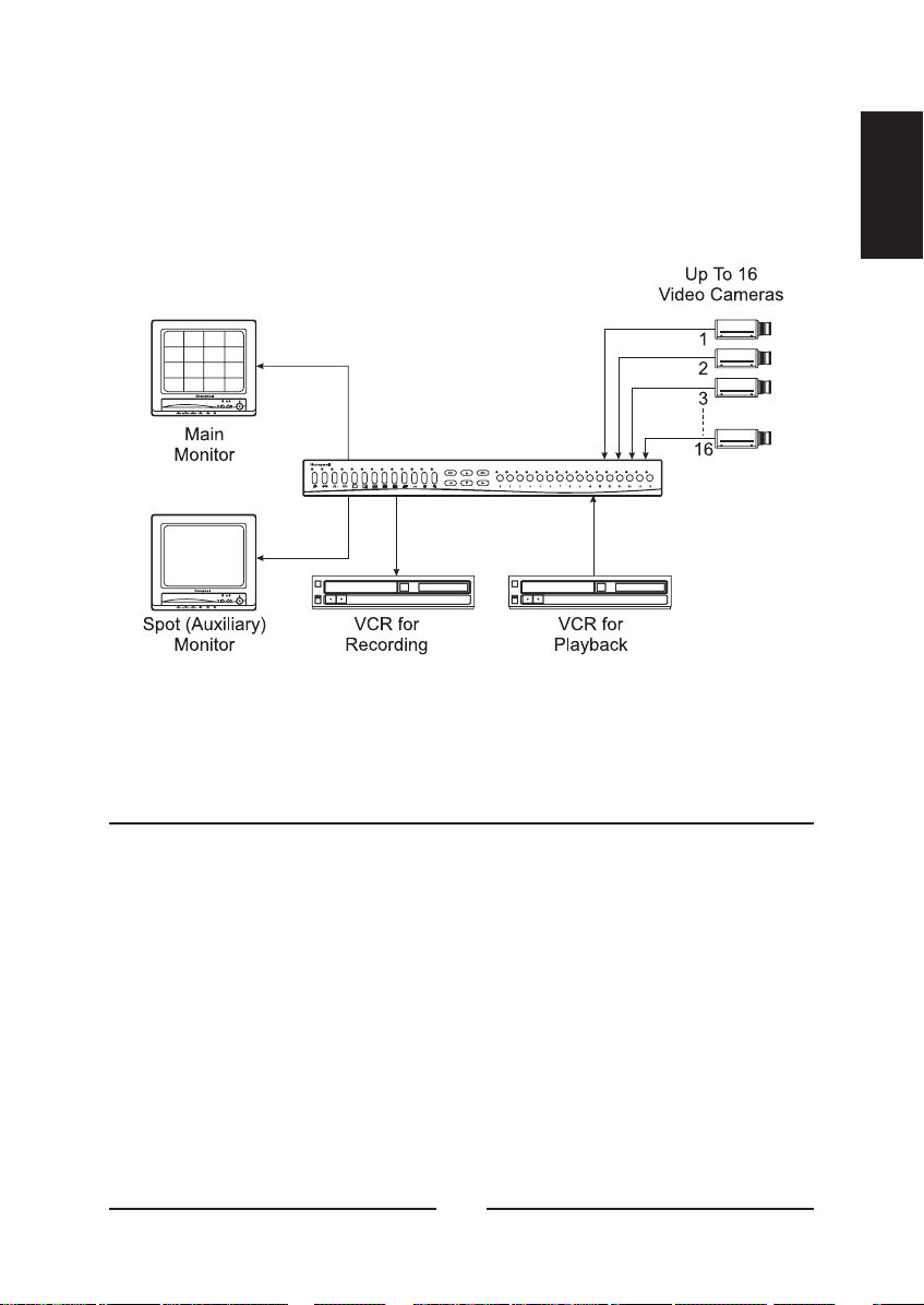
Figure 1 — Typical multiplexer system configuration 1
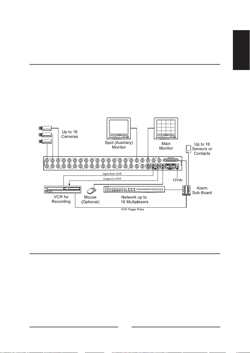
Figure 2 — connections 5
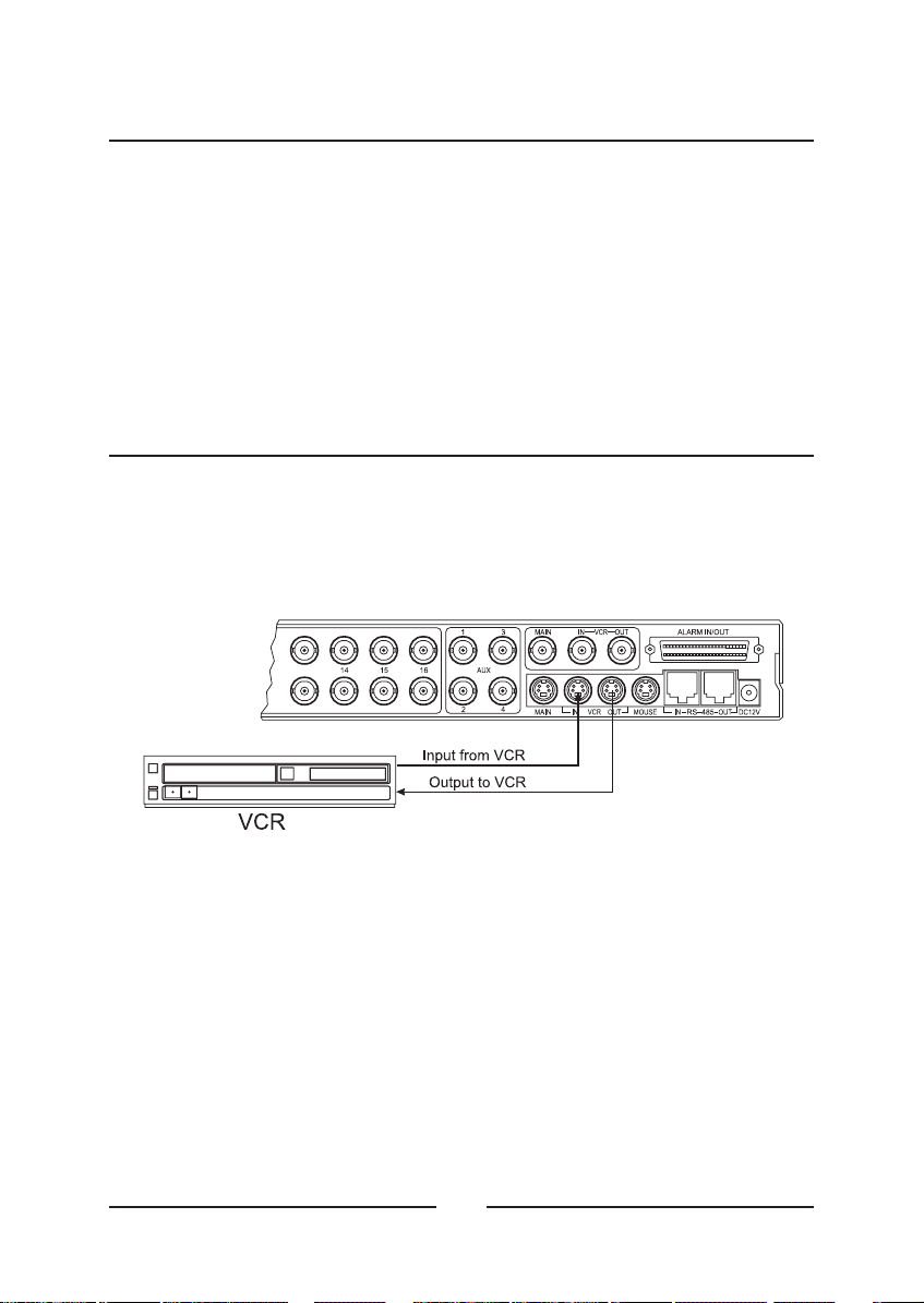
Figure 3 — Connecting one VCR to the 6
Figure 4 — Connecting two VCRs to the 7
Figure 5 — Top menu bar 8
Figure 6 — Supervisor Password screen 9
Figure 7 — Main Menu screen 10
Figure 8 — Time, Date Setup, first screen 10
Figure 9 — Time, Date Setup, second screen 12
Figure 10 — Camera Access Setup screen 13
Figure 11 — Camera Title Setup screen 14
Figure 12 — Camera Sequence Setup screen 15
Figure 13 — Alarm Setup screen 16
Figure 14 — Alarm I/O Setup screen 18
Figure 15 — Alarm Action Setup (1) screen 19
Figure 16 — Alarm Action Setup (2) screen 20
Figure 17 — Associated Camera Setup submenu 22
Figure 18 — Motion Action Setup (1) screen 23
Figure 19 — Motion Action Setup (2) screen 24
Figure 20 — Video Loss Action Setup screen 25
Figure 21 — Manual Alarm Action Setup (1) screen 27
Figure 22 — Manual Alarm Action Setup (2) screen 29
Figure 23 — Macro Link Setup screen 30
Figure 24 — Alarm History List screen 31
Figure 25 — Motion Detection Setup screen 32
Figure 26 — Motion Detection Index Setup screen 33
Figure 27 — Motion Detection Index List screen 34
Figure 28 — Motion Detection Schedule Setup schedule 35
Figure 29 — Motion Detection Sensor Setup screen 36
Figure 30 — Motion Detection Sensor Setup (Normal) screen 38
Figure 31 — Motion Detection Sensor Setup test screen 39
Figure 32 — Playback & Recording Setup screen 40
multiplexer
multiplexer
multiplexer
xii
Page 13

Figure 33 — VCR System Setup screen 41
—Figure 34 Recording Index Setup screen 42
Figure 35 — Camera Picture Adjustment screen 43
Figure 36 — Macro Setup screen 45
Figure 37 — Macro Record Setup screen 46
Figure 38 — Live screen with M01 REC on the screen 47
Figure 39 — Macro Schedule Setup screen 47
Figure 40 — Unit Setup screen 48
Figure 41 — Passwords Setup screen 50
Figure 42 — Password entry screen 51
Figure 43 — Front Panel 53
Figure 44 — Top Menu 56
Figure 45 — Bottom Menu 56
Figure 46 — 4x4 Live Screen 57
Figure 47 — Pop Up menu 58
Figure 48 — Live Cam Change menu 59
Figure 49 — VCR Cam Change menu 60
Figure 50 — Zoom Screen 61
Figure 51 — Histogram Equalizer menu bar 62
Figure 52 — Sequence menu 63
Figure 53 — Utilities Pop Up menu 64
Figure 54 — User Screen Change menu bar 64
Figure 55 — Select a Screen menu 65
Figure 56 — OSD Setup screen 66
Figure 57 — Spot output change screen 68
Figure 58 — User Change menu 68
Figure 59 — Alarm History List 69
Figure 60 — Select Format menu 70
Figure 61 — Connetor Sub-Board 72
Figure 62 — RS-485 Connector 73
ENGLISH
Table 1 — Re-Address Commands 74
Table 2 — Front key emulation commands 75
Table 3 — Remote commands 76
xiii
Page 14

xiv
Page 15
Chapter 1
Introduction
< Figure 1 > Typical system configuration.multiplexer
ENGLISH
Features
• Compatible with standard color cameras and other standard video
sources
• Switchable between NTSC and PAL
• Able to decode tapes from many other brands of multiplexers
• Many user-selectable display formats, Cameras can be assigned to
any display format
• Multiple monitor outputs (1 Main, 4 Auxiliary) allow simultaneous
multi-camera and full-screen viewing
• Multilingual setup menus include English, French, Italian, German,
Polish and Spanish
• On-screen display includes date, time, alarm status, video loss,
camera number and 24-character camera titles
• Programmable day and night motion-detection schedules
1
Page 16

• Each camera has a programmable 256-target (16 x 16) motion-
detection grid
• Programmable vector-based motion detection in any direction
• Nonvolatile program memory saves all user settings and protects
them against power outages
• One TTL/CMOS contact closure alarm for each camera
• Up to 4 cameras can be associated with a single contact closure
alarm
• Alarm input polarity is user selectable
• VCR switch pulse input for synchronization with VCRs having switch
pulse feature
• Full triplex operation allows simultaneous recording, playback and live
viewing
• 256-event alarm history log
• Linear Zoom in and out up to 32 times
2
Page 17

Technical Overview
16 Camera Multiplexing with Motion Detection, Alarm Association and
Multilingual Setup Menus
The has revolutionary features not available in most
multiplexer
multiplexers. The has a sophisticated motion detection
system that can sense motion vectors in any direction. Motion detection
sensitivity can be adjusted and the user can set day and night motion
detection schedules. A motion tracking box gives visual indications for
easy setup.
The has both composite BNC and Y/C mini DIN inputs and
multiplexer
outputs for VCRs. The main monitor can be connected to either a
composite BNC or Y/C mini DIN output. There are four BNC auxiliary
outputs that can be used for “spot” monitors or as sources of video for
other devices.
The has a large selection of user selectable display formats.
multiplexer
It also has digital zooming from 1 to 32 times.
The multilingual menu options allow for easy setup. The
multiplexer
user’s configuration is stored in nonvolatile memory so that it will not be
lost during power outages.
The can play back videotapes recorded with many other
multiplexer
multiplexers. These include, but are not limited to; HONEYWELL;
DAVE; ULTRAK Legacy Color; ULTRAK Legacy B/W; DM; ROBOT;
KALATEL. Up to 16 multiplexers can be “daisy chained” and addressed
and controlled by a single control panel. The multiplexer can also be
addressed by a computer using either an RS-232 or RS-485 connection.
multiplexer
ENGLISH
3
Page 18

4
Page 19
Chapter 2
Installation
Required Tools
Although no special tools are required to install the multiplexer, it is only
one part of a complex system. Refer to the Installation manuals for the
other components in your particular installation for special tool
requirements.
ENGLISH
< Figure 2 > connections.multiplexer
Connecting Cameras
You can connect up to 16 cameras to the . Connect the
camera BNCs to the IN BNC connectors (top row). The loop-through
connectors (OUT) are auto-terminated, so terminating resisters are not
needed if you do not loop video out to another device.
NOTE : Connecting a cable to the loop-through connector switches off
the termination. Do NOT connect a cable to the loop-through BNC
connectors unless it is connected to the input of another video device.
multiplexer
5
Page 20
Connecting Monitors
Your main monitor should be connected to the MAIN output. There are
two MAIN connectors; an S-Video and a BNC. If your monitor has an SVideo input, you should use the S-Video MAIN.
Up to four auxiliary monitors can be connected to the multiplexer. You
can use these as spot monitors or to view live video while playing tapes
back through the main monitor. The auxiliary monitors should be
connected to the AUX BNC connectors.
Connecting VCRs
There are both BNC and S-Video connectors for the VCRs. Use the SVideo connectors if your VCR has them because they will give you better
quality video.
< Figure 3 > Connecting one VCR to the .multiplexer
6
Page 21
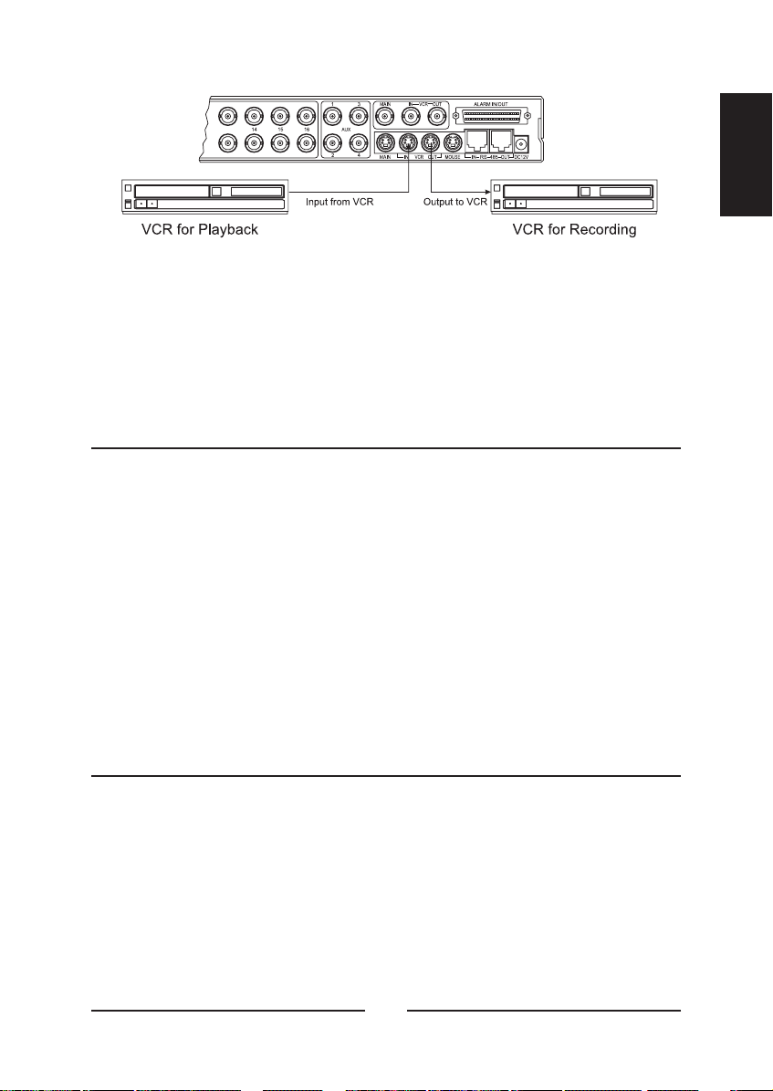
< Figure 4 > Connecting two VCRs to the .multiplexer
You can connect one VCR to the multiplexer and use it for both
recording and playback. However, the can handle recording
and playback at the same time, so it is possible to connect two VCRs.
One VCR is used to record while the other is used to play back. (See
the illustrations.)
multiplexer
Connecting a Mouse
The multiplexer menus can be controlled by either buttons on the front
panel or by a mouse. If you plan to use a mouse, connect it to the miniDIN connector labeled MOUSE.
The multiplexer is not compatible with all mouse available in the market.
Please note that users are recommended to use "Recommended
mouse" only described in the manual.
Logitech mouse (Ball mouse only)
ENGLISH
NOTE : Compatible mouse can be added without prior notice for better
performance.
Daisy- Chaining and Remote Control Connections
The can be daisy-chained to other multiplexers or controlled
multiplexer
by a remote keyboard. To add another multiplexer to your system,
connect the RS-485 OUT connector of the additional unit to the IN RS485 connector. (See Setup Menu section to set multiplexer address.)
The remote keyboard should be connected to the OUT connector on the
multiplexer.
7
Page 22

Alarms and Other Connections
The 50-pin ALARM IN/OUT connector has 16 alarm inputs, 16 alarm
outputs, RS-232 connectors, VCR trigger pulse and various alarm
settings. See Appendix B — Connector Pin Outs for further details on
how to make these connections.
Initial Setup
Setting up for NTSC or PAL Operation
NOTE : When changing the multiplexer to NTSC or PAL all other settings
are returned to the factory defaults.
The multiplexer can be used with either NTSC or PAL systems.
To set it up for NTSC operation:
1) Turn off the power
2) Press and hold the and {M} buttons.
3) Turn on the power
To set up the multiplexer for PAL operation:
1) Turn off the power
2) Press and hold the and buttons.
3) Turn on the power
Accessing the Main Menu
NOTE : To access the Main Menu you must have a Supervisor
Password. The last item of the Main Menu is the Password Setup.
Keep the passwords you create in a safe place. The new passwords will
be the only way to access certain features of the multiplexer once you
have changed from the factory default passwords.
< Figure 5 > Top menu bar.
8
Page 23
To access the Main Menu of the setup screens, move the cursor to the
top of the screen. The top menu bar appears. Select Setup.
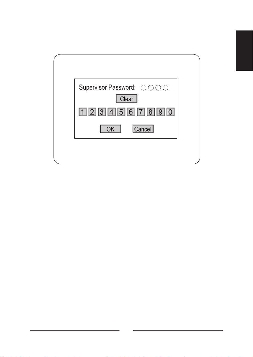
< Figure 6 > Supervisor Password screen.
Enter the password by moving the cursor over the desired number and
clicking on it. As you enter each digit, the circles beside “Supervisor
Password” fill in and move to the right. Once you have entered all four
digits, click on OK. If you have entered the correct four-digit number, the
Main Menu will appear. If you have entered an incorrect number,
Incorrect Password displays for ten seconds then the unit returns to a
live display.
ENGLISH
The factory default passwords are listed in the Technical Specifications.
Click on Cancel to exit the Supervisor Password screen and return to live
display.
9
Page 24
Main Menu Settings
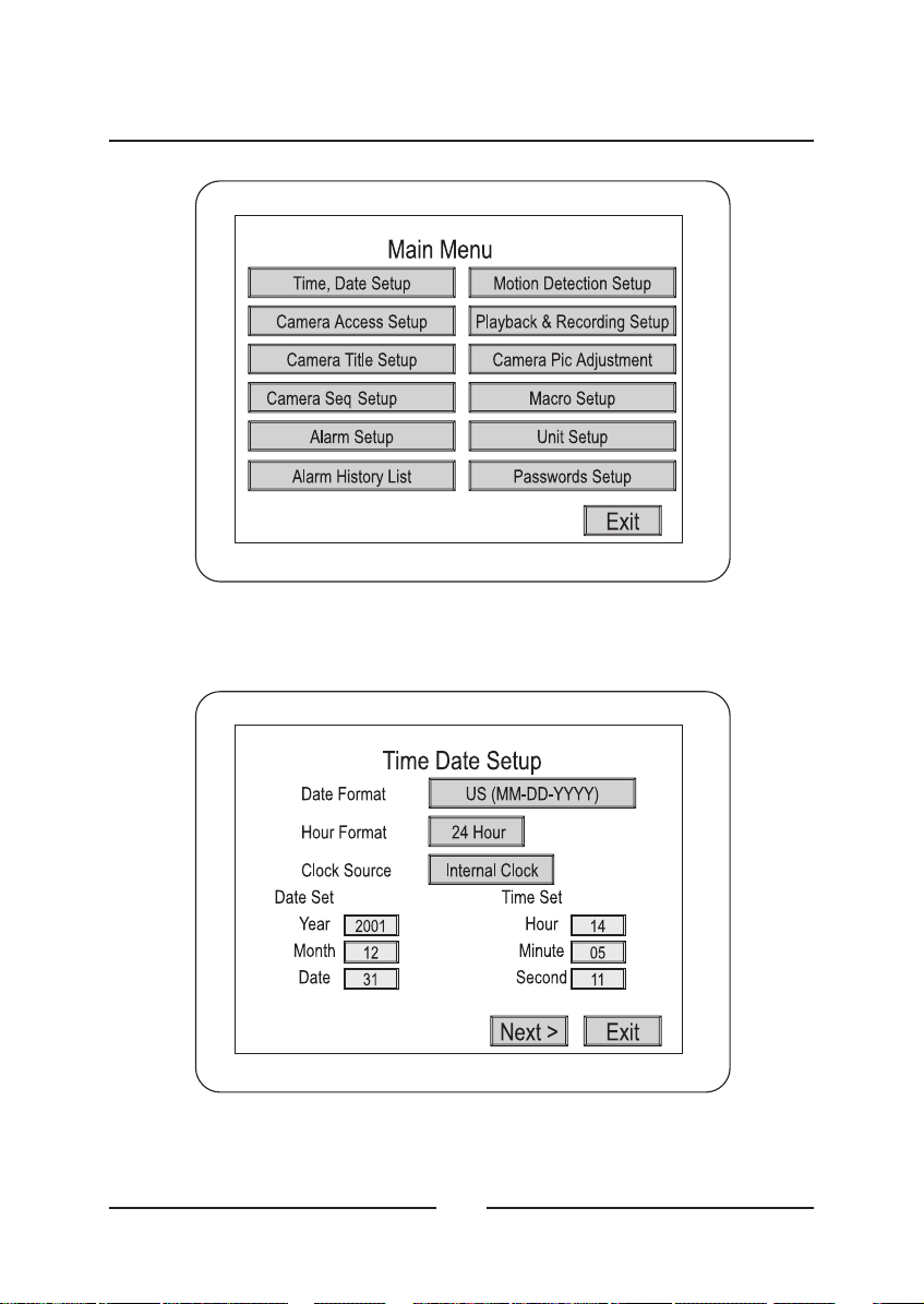
< Figure 7 > Main Menu screen.
< Figure 8 > Time, Date Setup, first screen.
10
Page 25

Time, Date Setup
In addition to setting the multiplexer’s time and date, these screens can
be used to set the format and select daylight saving time. You can use
the arrow buttons on the multiplexer or mouse to select the menu item.
Press SET or the left mouse button to decrease the number. Press ESC
or the right mouse button to increase the number.
ENGLISH
• Date format :
month and days are each two-digit numbers represented by MM and
DD. Years are four-digit numbers represented by YYYY. The U.S.
format is: MM-DD-YYYY. Europe’s format is: DD-MM-YYYY. Asia’s
format is: YYYY-MM-DD.
• Hour format :
hour (military) time. The second is AM/PM.
• Clock Source :
multiplexer is connected to a network, set the option to Network Clock
and the unit will receive the clock information from the master
multiplexer. If your multiplexer is not connected to a network, set the
option to Internal Clock.
• Year :
• Month :
• Date :
• Hour :
• Minute :
• Second :
Use the arrow or mouse buttons to change the year.
Use the arrow or mouse buttons to change the date.
Use the arrow or mouse buttons to change the hour.
There are three date formats to choose from. The
There are two hour formats to choose from. One is 24-
There are two choices for the clock source. If your
Use the arrow or mouse buttons to change the month.
Use the arrow or mouse buttons to change the minute.
Use the arrow or mouse buttons to change the second.
• Next > : Selecting this takes you to the second Daylight Saving
setup Screen.
11
Page 26
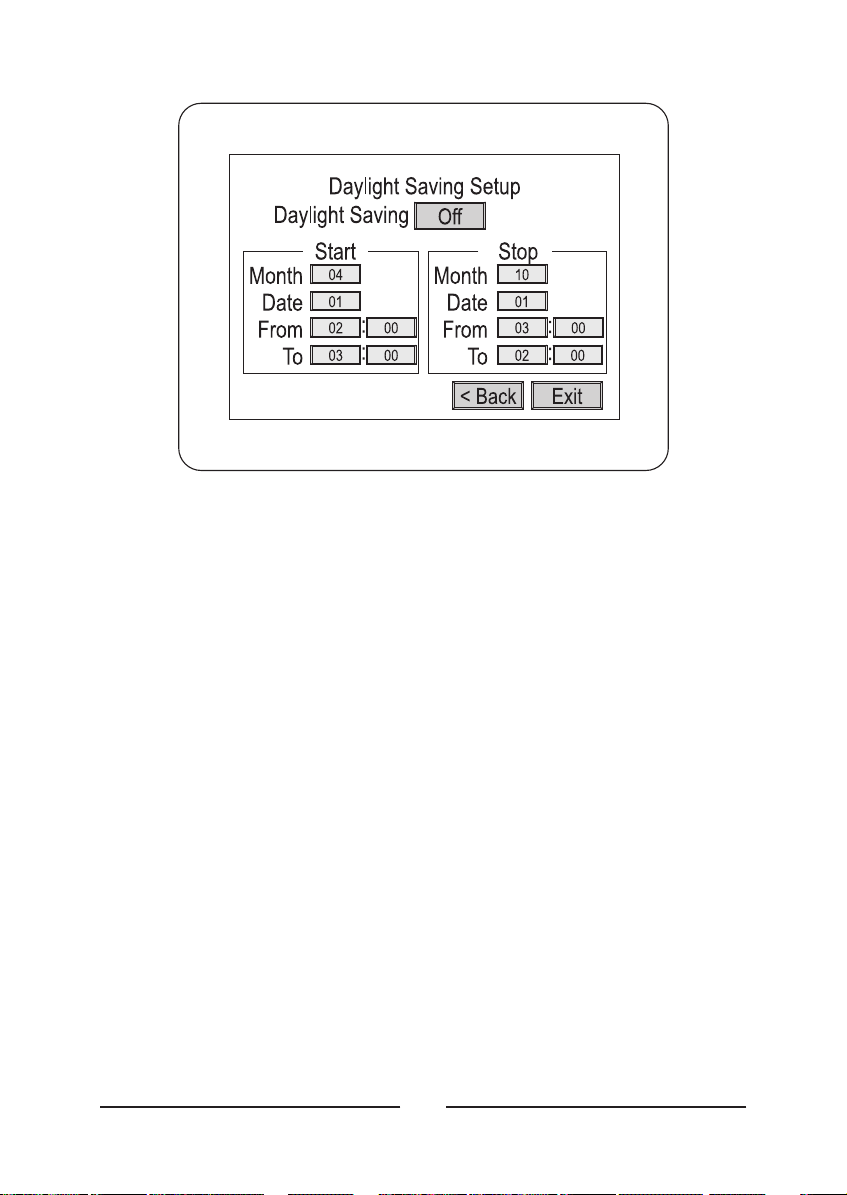
< Figure 9 > Time, Date Setup, second screen.
• Daylight Saving :
If you are in an area that does not have Daylight
Saving (Summer) Time, set this option to Off. When you set this
selection to On, you must set the start and stop dates and times.
• Start :
Set the Month and Date that your area begins Daylight Saving
time. Unless there is an unusual situation, you will not need to set
From and To times.
• Stop :
Set the Month and Date that your area ends Daylight Saving
time. Unless there is there is an unusual situation, you will not need to
set From and To times.
• < Back :
Selecting this takes you back to the first Time, Date Setup
Screen.
• Exit :
Selecting this saves your settings and exits the Time, Date
Setup screens.
12
Page 27
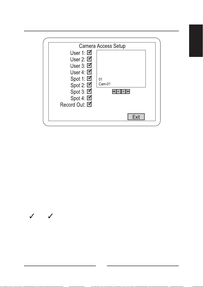
Camera Access Setup
< Figure 10 > Camera Access Setup screen.
The Camera Access Setup screen allows you to assign which cameras
different users will have access to and which cameras can be displayed
on the Spot (auxiliary) monitors. You can also designate whether a
camera can be recorded.
ENGLISH
•<<:
•<:
•>:
•>>:
•:
•O:
• Exit :
Goes to Camera 1
Goes back one camera
Goes forward one camera.
Goes to Camera 16
An next to an item activates the camera for that output.
An deactivates the camera.
Saves your changes and returns to the Main Menu.
O
13
Page 28
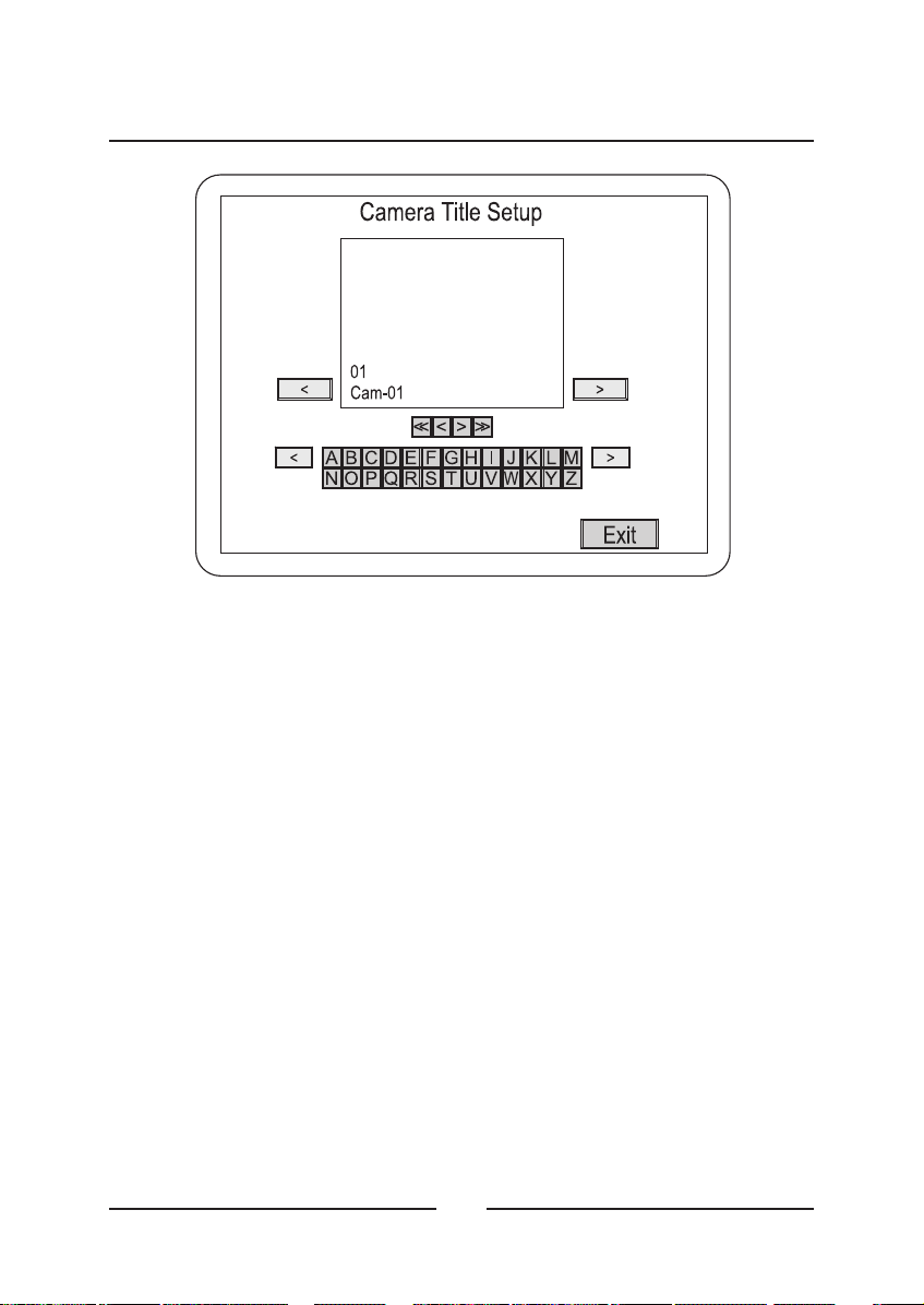
Camera Title Setup
< Figure 11 > Camera Title Setup screen.
The Camera Title Setup screen allows you to enter titles for each
camera. Clicking on the letters and characters enters them in the
camera title. Each camera title can have a maximum of 24 characters.
•Top<:
• Top>:
• Middle << :
• Middle < :
• Middle > :
• Middle >> :
• Bottom < :
• Bottom > :
Moves the cursor left.
Moves the cursor right.
Goes to Camera 1.
Goes back one camera.
Goes forward one camera.
Goes to Camera 16.
Changes the keyboard characters to the previous set.
Changes the keyboard characters to the next set.
14
Page 29
• Keyboard Character Set 1 :
A to Z (upper case)
ENGLISH
• Keyboard Character Set 2 :
• Keyboard Character Set 3 :
• Keyboard Character Set 4 :
• Keyboard Character Set 5 :
ЫЬЯабв
• Exit :
Saves your changes and returns to the Main Menu.
АБВДЗИЙКЛМНОПСТУФЦЩЪ
дзийклмнопстуфцщъыь• Keyboard Character Set 6 :
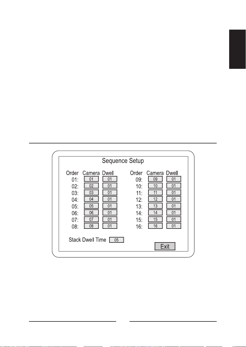
Camera Sequence Setup
a to z (lower case)
BLANK !"#$%&'()*+,-./0to9
:;<=>?[\]^_'{I}~
< Figure 12 > Camera Sequence Setup screen.
This screen allows you to set the order in which the cameras appear
when the multiplexer is in sequence mode. You can also set the how
long each camera will display from Off to 99 seconds.
15
Page 30
Enter the camera number under the Camera column and the display
time under Dwell. You can also set the Stack Dwell Time, which is the
length of time each group of cameras will display.
Saves your changes and returns to the Main Menu.• Exit :
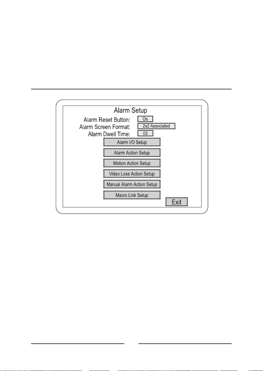
Alarm Setup
< Figure 13 > Alarm Setup screen.
The Alarm Setup screen allows you to enter six alarm submenus.
• Alarm Reset Button :
events using the front panel buttons or the Pop Up menu. Setting it to
Off requires the user to enter the Setup Menus to clear alarm events.
• Alarm Screen Format :
will use when an alarm occurs. There are five possible settings: Full,
2x2, 2x2 Associated, 4x4 and Unchanged.
Setting this to On allows users to clear alarm
This sets the display mode the multiplexer
16
Page 31

• Alarm Dwell Time : The dwell time can be set from 1 to 99 seconds.
(The screen will automatically sequence in a multi-alarm condition.)
ENGLISH
• Alarm I/O Setup :
• Alarm Action Setup :
• Motion Action Setup :
• Video Loss Action Setup :
• Manual Alarm Action Setup :
submenu.
• Macro Link Setup :
• Exit :
Saves your changes and returns to the Main Menu.
Enters the Alarm I/O Setup submenu.
Enters the Alarm Action Setup submenu.
Enters the Motion Action Setup submenu.
Enters the Video Loss Action submenu.
Enters the Macro Link Setup submenu.
Enters the Manual Alarm Action Setup
17
Page 32

Alarm I/O Setup
< Figure 14 > Alarm I/O Setup screen.
You can set the input and output for each of the alarm connections.
•In:
Off.
• Out :
• Exit :
Can be set to NO (Normally Open), NC (Normally Closed) or
Can be set to AH (Active High) or AL (Active Low) TTL output.
Saves your changes and returns to the Main Menu.
18
Page 33

Alarm Action Setup (1)
< Figure 15 > Alarm Action Setup (1) screen.
This screen allows you to set up the actions the multiplexer will take
when there is an alarm condition.
ENGLISH
• Buzzer :
during an alarm condition.
• Alarm Screen :
one defined in the Alarm Screen Format menu during an alarm
condition.
• Network Relay :
information to an external relay box via the network during an alarm
condition.
• Message Latch :
an alarm condition occurs. It remains on the screen until it is cleared.
When set to On, the multiplexer’s internal buzzer will sound
When set to On, the screen display will change to the
When set to On, the multiplexer sends the alarm
When set to On, an “A” displays on the screen when
19
Page 34

• Recording :
alarm condition. INT interleaves images from the camera with an
alarm every other field giving you more images from that camera.
When there are multiple alarms, the cameras with alarms are
interleaved.
ONLY records images from only the camera with an alarm condition.
UNC leaves the recording parameters unchanged.
This allows you to select how video will record during an
• Spot Monitor 1 to 4 :
the camera with an alarm condition. When there are multiple alarms,
cameras with alarms will display sequentially. When set to Off, that
Spot Monitor’s display does not change during alarm conditions.
• Hold Time :
1 to 99 seconds. Hold Time is applicable only if the alarm action is set
to Timed OUT.
• Next > :
• Exit :
Saves your changes and returns to the Main Menu.
This allows the user to set the alarm actions to last from
This takes you to the Alarm Action Setup (2) submenu.
When set to On, that Spot Monitor will display
Alarm Action Setup (2)
< Figure 16 > Alarm Action Setup (2) screen.
20
Page 35

This screen allows you to set the actions the operator can take, what
relays will be activated and what cameras are associated with other
cameras.
ENGLISH
• Action :
“time out” at the designated time (Hold Time) unless the operator
clears it earlier. Latched: The alarm remains active until the operator
acknowledges it. Trans (Transparent): The alarms are not latched and
cannot be cleared by the operator.
• Relay :
internal relay 1 or 2 to be activated by an alarm. 1&2: Sets both
internal relays 1 and 2 to be activated by an alarm. Off: Neither
internal relay will be activated by an alarm.
• Associated :
a camera that is in an alarm condition. Selecting this item will take
you to the Associated Camera Setup submenu.
• < Back :
• Exit :
There are three possible settings. Timed: The alarm will
There are four possible relay settings. 1 or 2: Sets either
This button allows you to associate other cameras with
This takes you to the Alarm Action Setup (1) submenu.
Saves your changes and returns to the Main Menu.
21
Page 36

Associated Camera Setup
< Figure 17 > Associated Camera Setup submenu.
This menu allows you to associate up to three cameras with another
when an alarm condition occurs. The main camera is displayed in the
top window with the three associated cameras shown below. Under
each of the associated camera windows is a control bar.
Goes through the cameras in reverse order.
•<:
• On/Off :
with the camera with the alarm condition. (If all three Associated
Cameras are set to Off, no cameras will be associated to the camera
with that camera.)
•>:
• Exit :
By setting this to On, the selected camera will be associated
Goes through the cameras in forward order.
Saves your changes and returns to the previous menu.
22
Page 37

Motion Action Setup (1)
< Figure 18 > Motion Action Setup (1) screen.
This screen allows you to set up the actions the multiplexer will take
when there is a motion alarm condition.
ENGLISH
• Buzzer :
during a motion alarm condition.
• Alarm Screen :
one defined in the Alarm Screen Format menu during a motion alarm
condition.
• Network Relay :
information to an external relay box via the network during a motion
alarm condition.
• Message Latch :
when a motion alarm condition occurs. It remains on the screen until
it is cleared.
When set to On, the multiplexer’s internal buzzer will sound
When set to On, the screen display will change to the
When set to On, the multiplexer sends the alarm
When set to On, an “M” displays on the screen
23
Page 38

• Recording :
motion alarm condition. INT interleaves images from the camera with
an alarm every other field giving you more images from that camera.
When there are multiple alarms, the cameras with alarms are
interleaved. ONLY records images from only the camera with an
alarm condition. UNC leaves the recording parameters unchanged.
This allows you to select how video will record during a
• Spot Monitor 1 to 4 :
the camera with a motion alarm condition. When there are multiple
alarms, cameras with alarms will display sequentially. When set to Off,
that Spot Monitor’s display does not change during motion alarm
conditions.
• Next > :
submenu.
• Exit :
This takes you to the Motion Alarm Action Setup (2)
Saves your changes and returns to the Main Menu.
When set to On, that Spot Monitor will display
Motion Action Setup (2)
< Figure 19 > Motion Action Setup (2) screen.
24
Page 39

This screen allows you to associate various relays and links to the
cameras in motion alarm conditions.
ENGLISH
• Relay :
internal relay 1 or 2 to be activated by a motion alarm. 1&2: Sets both
internal relays 1 and 2 to be activated by a motion alarm. Off: Neither
internal relay will be activated by a motion alarm.
• Alarm Link :
It can be set to Off or any one of the 16 alarm actions. All alarm
actions take priority over motion actions.
• < Back :
submenu.
• Exit :
There are four possible relay settings. 1 or 2: Sets either
This button links the motion detection to an alarm action.
This takes you to the Motion Alarm Action Setup (1)
Saves your changes and returns to the Main Menu.
Video Loss Action Setup
< Figure 20 > Video Loss Action Setup screen.
This screen allows you to set up the actions the multiplexer will take
when there is a video loss condition.
25
Page 40

• Buzzer :
When set to On, the multiplexer’s internal buzzer will sound
during a video loss condition.
• Alarm Screen :
When set to On, the screen display will change to the
one defined in the Alarm Screen Format menu during a video loss
condition.
• Internal Relay :
Selects which internal relays will be activated during
a video loss condition. 1 or 2 activates the designated relay. 1&2
activates both internal relays. Off means neither relay will activate.
• Network Relay :
When set to On, the multiplexer sends the video loss
information to an external relay box via the network during a video
loss condition.
• Message Latch :
When set to On, a “V” displays on the screen when
a video loss condition occurs. It remains on the screen until it is
cleared.
• Spot Monitor 1 to 4 :
When set to On, that Spot Monitor will display
the camera with a video loss condition. When there are multiple
alarms, cameras with alarms will display sequentially. When set to
Off, that Spot Monitor’s display does not change during video loss
conditions.
• Hold Time :
This allows the user to set the actions to last from 1 to 99
seconds.
• Exit :
Saves your changes and returns to the previous menu.
26
Page 41

Manual Alarm Action Setup (1)
< Figure 21 > Manual Alarm Action Setup (1) screen.
This screen allows you to set up the actions the multiplexer will take
when there is a Manual alarm condition.
ENGLISH
• Buzzer :
during a Manual alarm condition.
• Alarm Screen :
one defined in the Alarm Screen Format menu during a Manual alarm
condition.
• Network Relay :
information to an external relay box via the network during a Manual
alarm condition.
• Message Latch :
a Manual alarm condition occurs. It remains on the screen until it is
cleared.
When set to On, the multiplexer’s internal buzzer will sound
When set to On, the screen display will change to the
When set to On, the multiplexer sends the alarm
When set to On, an “A” displays on the screen when
27
Page 42

• Recording :
This allows you to select how video will record during a
Manual alarm condition. INT interleaves images from camera with an
alarm every other field giving you more images from that camera.
When there are multiple alarms, the cameras with alarms are
interleaved. ONLY records images from only the camera with an
alarm condition. UNC leaves the recording parameters unchanged.
• Spot Monitor 1 to 4 :
When set to On, that Spot Monitor will display
the camera with a Manual alarm condition. When there are multiple
alarms, cameras with alarms will display sequentially. When set to
Off, that Spot Monitor’s display does not change during Manual alarm
conditions.
• Hold Time :
This allows the user to set the alarm actions to last from
1 to 99 seconds. Hold Time is applicable only if the alarm action is set
to Timed OUT.
• Next > :
This takes you to the Manual Alarm Action Setup (2)
submenu.
• Exit :
Saves your changes and returns to the previous menu.
28
Page 43

Manual Alarm Action Setup (2)
< Figure 22 > Manual Alarm Action Setup (2) screen.
This screen allows you to set the actions the operator can take, what
relays will be activated and what cameras are associated with other
cameras.
ENGLISH
• Action :
“time out” at the designated time (Hold Time) unless the operator
clears it earlier.
Latched : The alarm remains active until the operator acknowledges
it. Trans (Transparent): The alarms are not latched and cannot be
cleared by the operator.
• Relay :
internal relay 1 or 2 to be activated by an alarm. 1&2: Sets both
internal relays 1 and 2 to be activated by an alarm. Off: Neither
internal relay will be activated by an alarm.
• Alarm Link : This selects whether the alarm action will be linked or
not. It can be set to Off or any of the 16 alarm actions. All alarm
actions take priority over manual alarm actions.
There are three possible settings. Timed: The alarm will
There are four possible relay settings. 1 or 2: Sets either
29
Page 44

• <Back :
submenu.
This takes you to the Manual Alarm Action Setup (1)
• Exit :
Saves your changes and returns to the previous menu.
Macro Link Setup
< Figure 23 > Macro Link Setup screen.
This screen allows you to link macros to the 16 alarms. Each alarm can
be set to Off or linked to any of 16 macros.
Saves your changes and returns to the previous menu.• Exit :
30
Page 45

Alarm History
ENGLISH
< Figure 24 > Alarm History List screen.
This screen displays a list of alarms. The retains a history of
up to 256 events.
•<<:
•<:
•>:
•>>:
• Clear :
NOTE : Before implement "Print" function, make sure follow the below
steps.
1. Go to the vender's website.
Goes to the first page in the history list.
Goes back one page in the history list.
Goes forward one page in the history list.
Goes to the last page in the history list. (maximum 16 pages)
This clears all the information from the history list. You will be
asked to confirm that you really want to delete all the alarm history
information before it is deleted.
Transmits all alarm history list to PC.• Print :
multiplexer
31
Page 46

2. Download the "Download.exe" file on your PC.
3. Implement the "Download.exe" file and click the icon named
"Print Program".
4. Now user's are ready to use "Print" function.
• Exit : Saves your changes and returns to the Main Menu.
Motion Detection Setup
< Figure 25 > Motion Detection Setup screen.
The Motion Detection Setup screen is the starting point for various
motion detection setup screens.
• All Motion Detection:
detection for all cameras On or Off.
• Motion Detection Index Setup:
• Motion Detection Schedule Setup:
• Motion Detection Sensor Setup:
• Exit:
Saves your changes and returns to the Main Menu.
This is a global switch that turns motion
Takes you to that submenu.
Takes you to that submenu.
Takes you to that submenu.
32
Page 47

Motion Detection Index Setup
< Figure 26 > Motion Detection Index Setup screen.
Normally, the multiplexer gives equal priority to all cameras (1 to 16) for
motion detection. However, it is possible to change the priorities.
ENGLISH
•+:
•- :
•<:
•>:
• Delete :
• Insert :
• End :
• View :
• Exit :
Increases the camera number by one.
Decreases the camera number by one.
Scrolls through the camera array to the left.
Scrolls through the camera array to the right.
Deletes the highlighted camera from the array.
Inserts a blank into the array.
Enters an “E” which sets the end mark for the index list.
Displays the Motion Detection Index List.
Saves your changes and returns to the previous menu.
33
Page 48
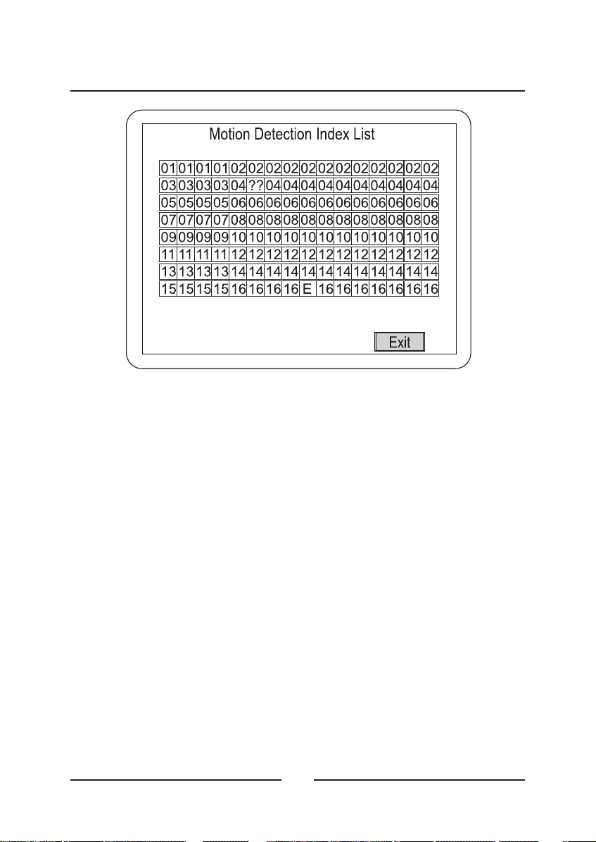
Motion Detection Index List
< Figure 27 > Motion Detection Index List screen.
This screen displays the priorities assigned to the cameras. You cannot
edit anything on this screen.
Returns to the previous menu.• Exit :
34
Page 49

Motion Detection Schedule Setup
< Figure 28 > Motion Detection Schedule Setup schedule.
The can be set up to detect or ignore motion based on a
multiplexer
schedule. For example, you would expect lots of activity during normal
office hours and do not want to detect motion. However, when the office
is closed, motion should generate an alarm condition.
ENGLISH
• Timer1&2:
to Mode 1 or 2. (Modes 1 and 2 are defined in the Motion Detection
Sensor Setup screen.)
• Start & Stop :
start time of 18:00 with an end time of 06:00 will go from 6:00 p.m.
until 6:00 a.m. of the following morning.
• Days :
=Onand =Off.
• Exit :
Saves your changes and returns to the previous menu.
Each timer can be turned On or Off, and they can be set
You can set the start and stop time for each timer. A
The timers can be turned On or Off for each day of the week.
O
35
Page 50
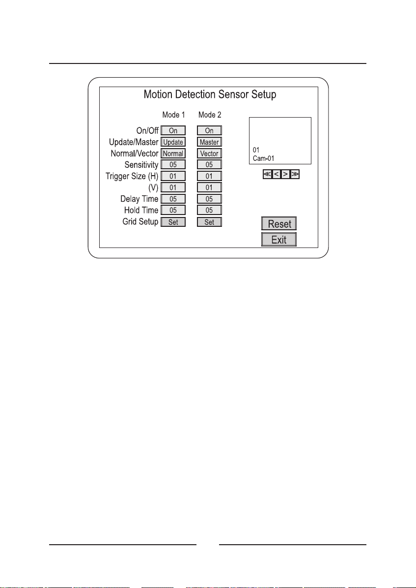
Motion Detection Sensor Setup
< Figure 29 > Motion Detection Sensor Setup screen.
Each camera can be set up with two sets of motion detection
parameters. The parameter sets are defined as Mode 1 and Mode 2.
(You can schedule when the modes will be used in the Motion Detection
Schedule Setup screen.)
• On/Off :
• Update/Master :
current field with the previous one. When using Master, the
multiplexer compares a master image to continuous video.
• Normal/Vector :
motion. When set to Vector, the multiplexer detects motion based on
user definitions.
• Sensitivity :
target area before the multiplexer reads the change as motion. 01 is
the lowest sensitivity and 16 is the highest.
Turns motion detection On or Off.
When using Update, the multiplexer compares the
When set to Normal, the multiplexer detects all
Sets how much luminance change there must be in the
36
Page 51

• Trigger Size (H) :
horizontal row that must change before the multiplexer reads the
change as motion. The range is 01 to 16.
This is the minimum number of targets in a
ENGLISH
• Trigger Size (V) :
row that must change before the multiplexer reads the change as
motion. The range is 01 to 16.
• Delay Time :
that have sudden changes such as lights and shadows created by
headlights of nearby traffic. The delay can be set from 0 to 5 seconds.
• Hold Time :
• Grid Setup :
•<<:
•<:
•>:
•>>:
• Reset : Returns all settings to the motion detection sensor setup
• Exit :
Goes to Camera 1.
Goes back one camera.
Goes forward one camera.
Goes to Camera 16.
default.
Saves your changes and returns to the previous menu.
This is the minimum number of targets in a vertical
The delay time is used to make adjustments for scenes
The Hold Time can be set from 1 to 99 seconds.
Takes you to the Motion Detection Sensor Setup screen.
37
Page 52

Motion Detection Sensor Setup (Normal)
< Figure 30 > Motion Detection Sensor Setup (Normal) screen.
The Motion Detection Sensor Setup screen is used to setup and test
cameras for motion detection. Mode 1 and Mode 2 can be set up for
either Normal or Vector motion detection. The following describes
Normal motion detection.
• Highlights the grids area.
SET :
Click of the mouse on this icon has no action.
• Dot/Line/All :
Dot = single target. Line = a row of targets. All = all the targets.
• Reverse :
• Test :
• Exit :
Goes to the Motion Detection Sensor Setup test screen.
Saves your changes and returns to the previous menu.
Determines how many targets will be turned on or off.
Set all targets to the reverse side.
38
Page 53

Testing Motion Detection Sensor Setup
< Figure 31 > Motion Detection Sensor Setup test screen.
The Motion Detection Sensor Setup test screen shows when the
multiplexer detects motion by drawing a box around the active area.
This gives you instant feedback letting you know if you have set the
correct size and sensitivity for the types of motion you want to detect.
ENGLISH
• Master Screen Set :
appears in the Master Mode.)
• Exit :
Returns to the previous menu.
Saves the master image. (This button only
39
Page 54
Motion Detection Sensor Setup (Vector)
The Vector Motion Detection Sensor Setup screen is the same as the
Normal Motion Detection Sensor Setup screen except that it has two
motion grids. To detect left to right motion, you define the first grid and
then define a second grid to the right of the first.
• A ON :
• B ON :
Refer to Motion Detection Sensor Setup (Normal) for descriptions of all
the other settings.
Used to define the first grid.
Used to define the second grid.
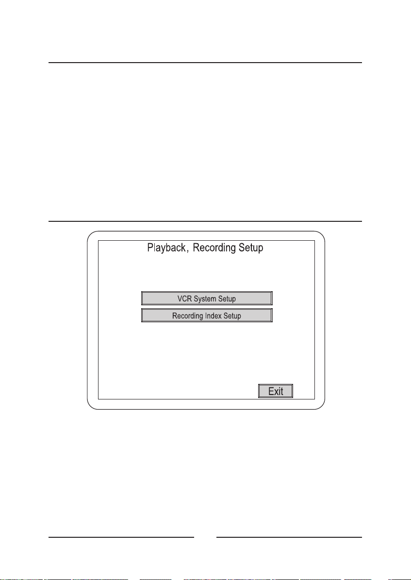
Playback & Recording Setup
< Figure 32 > Playback & Recording Setup screen.
The Playback & Recording Setup screen gives you access to submenus
for setting up playback and recording.
• VCR System Setup :
• Recording Index Setup :
• Exit :
Saves your changes and returns to the Main Menu.
Opens the submenu.
Opens the submenu.
40
Page 55

VCR System Setup
< Figure 33 > VCR System Setup screen.
ENGLISH
The VCR System Setup screen is used to synchronize the
with your VCR.
NOTE : If your VCR has a synchronizing trigger pulse, using it will save
you a lot of time when setting up your system.
• VCR Input :
VCR: BNC and S-Video.
• External Trigger :
synchronizing trigger pulse. When using your VCR’s synchronizing
trigger pulse, set to match the VCR’s signal; + for positive edge
sensing and – for negative edge sensing.
• Panic Rec Buzzer :
seconds.
• VCR Type :
from the list. If your VCR is not on the list select User Define.
There are two options for multiplexer input from the
Set to Off if you are not using the VCR’s
When On, the buzzer will beep every 20
Selecting this brings up a list of VCRs. Select your VCR
41
multiplexer
Page 56

• Normal & Alarm Record :
need to set is the hours. If you selected User Define, you need to set
the hours and field delay. Although you can set Normal and Alarm
hours the same, you usually want higher quality video in an alarm
situation. For example, you might set Normal to 24-hour time-lapse
and Alarm to 2-hour mode. You will need to get the field delay rates
from your VCR manufacturer.
If you selected a VCR from the list, all you
• Exit :
Saves your changes and returns to the previous menu.
Recording Index Setup
< Figure 34 > Recording Index Setup screen.
Normally, the multiplexer gives the same priority to all cameras.
However, you can set it up so that cameras are given different recording
priorities.
•+:
•-:
•<:
•>:
Increases the camera number by one.
Decreases the camera number by one.
Scrolls through the camera array to the left.
Scrolls through the camera array to the right.
42
Page 57

• Delete :
Deletes the highlighted camera from the array.
ENGLISH
• Insert :
• End :
• View :
• Exit :
Inserts a blank into the array.
Enters an “E” which sets the end mark for the index list.
Displays the Motion Detection Index List.
Saves your changes and returns to the previous menu.
Camera Picture Adjustment
< Figure 35 > Camera Picture Adjustment screen.
NOTE : Do not make any adjustments with this screen until all of the
cameras and monitors have been adjusted properly.
•<<:
•< :
•> :
•>>:
Goes to Camera 1.
Goes back one camera.
Goes forward one camera.
Goes to Camera 16.
43
Page 58

The following adjustments have a default setting of 00. The other values
are Min = minimum, 127 to -01 = adjustments below default, 01 to 127 =
adjustments above default, and Max = maximum.
• Contrast :
• Color :
• Brightness :
• Tint :
operation.)
• Sharpness : Adjusts sharpness.
• Exit :
Adjusts contrast.
Adjusts color.
Adjusts brightness.
Adjusts tint. (Not available when the multiplexer is set for PAL
Saves your changes and returns to the Main Menu.
44
Page 59

Macro Setup
< Figure 36 > Macro Setup screen.
The Macro Setup screen lets you access the two macro setup
submenus.
ENGLISH
• Macro Recording Setup :
• Macro Schedule Setup :
• Exit :
Saves your changes and returns to the Main Menu.
Opens the submenu.
Opens the submenu.
45
Page 60

Macro Record Setup
< Figure 37 > Macro Record Setup screen.
Selecting any of the Record Start buttons takes you to a live screen
where all of your key strokes or mouse operations except for password
protected operations will be recorded as a macro.
Saves your changes and returns to the previous menu.• Exit :
46
Page 61

< Figure 38 > Live screen with M01 REC on the screen.
Macro Schedule Setup
ENGLISH
< Figure 39 > Macro Schedule Setup screen.
47
Page 62

You can create up to 20 event schedules that use macros.
• Event :
• On/Off :
• Macro :
• Time :
• Day :
O
• Exit :
Scheduled event number; 01 through 20
Turns the selected event On or Off.
Selects the macro that that event is to perform.
Sets the time the event is to be done.
Sets the day(s) the event is to be done. = enables the event.
= disables the event.
Saves your changes and returns to the previous menu.
Unit Setup
< Figure 40 > Unit Setup screen.
This screen allows you to change the basic settings.
• Language :
Italian, German, Polish and Spanish.
There are five languages available: English, French,
multiplexer
48
Page 63

• Mouse :
this to On.
If you plan to use a mouse to control you multiplexer, set
ENGLISH
• Key lock :
open a screen asking for a password.
• Factory Reset :
A confirmation screen will ask you if you really want to reset
everything.
• Cam No. Offset :
camera numbers based on the Unit Address. Unit 001 will have
Cameras 01 to 16, Unit 002 will have Cameras 17 to 32, etc. When
set to Off, the cameras will be numbered 01 to 16.
Mouse setup : If the mouse cannot be worked properly, the user can
•
change the values as follows.
The ranges which can be changed are Min=minimum, -009~009 and
Max=maximum.
• Master/Slave :
determine if the unit is a master or slave unit.
• Network Type :
RS-485 when connected to a network.
• Baud Rate :
to 1200, 2400, 4800, 9600 or 19200.
When On, pressing any key or clicking the mouse will
Returns all settings to the factory default.
When set to On, the multiplexer will adjust the
When installed as part of a network, this will
The can be set to RS-232, RS-422 or
multiplexer
When connected to a network, the baud rate can be set
• Unit Address :
from 001 to 255.
• Protocol :
B1 is dome camera control protocol.
• Exit :
Saves your changes and returns to the Main Menu.
Networked multiplexers can be assigned addresses
A is multiplexer protocol.
49
Page 64

Password Setup
< Figure 41 > Passwords Setup screen.
NOTE : Keep a copy of the supervisor password in a safe place. Once
you have changed the supervisor password from the factory default, you
will not be able to access protected menus without it.
The Password Setup screen allows you to assign PIN codes to the
supervisor and up to four users.
• Setup Menu Password :
and make changes in the Setup Menu.
• User Change Password :
make screen configuration changes or to access items on the Pop Up
menu.
• Supervisor :
• User1to4:
• Exit :
Saves your changes and returns to the Main Menu.
Opens the Password Entry screen.
Opens the Password Entry screen.
When On, only the supervisor can enter
When On, a password will be required to
50
Page 65

Assigning Passwords
< Figure 42 > Passwords entry screen.
Use the numbers to enter a four-digit PIN.
ENGLISH
• Clear :
•OK:
to the first password, and exits the Setup Menu if they match.
• Cancel :
Deletes all entered numbers, and you can restart entry.
Opens the re-enter screen after the first try. Compares the entry
Cancels the password setup and exits the Setup Menu.
51
Page 66

52
Page 67

Chapter 3
Operation
< Figure 43 > Front Panel.
Buttons and Their Functions
Allows the operator to generate an alarm. When pressed along with
a camera button, it places that camera in the alarm mode.
ENGLISH
• OPERATION :
Pressing this button switches the multiplexer into VCR playback
mode or VCR preview mode.
• OPERATION :
mode. Press 2nd and then to switch the VCR to preview mode.
Plays a Macro.
{M}
• OPERATION : {M}
to 16.
Puts a camera in the Panic Record Mode.
REC
• OPERATION : REC
camera in the panic record mode.
Puts the multiplexer in Full-Screen Mode or the first user-defined
display mode.
Press and then a camera button.
Press to switch the multiplexer into VCR playback
Press and then a camera button to play macros 1
Press and then a camera button to put that
53
Page 68

• OPERATION :
Press and the currently selected camera displays
full screen. Pressing another camera button will display that camera
full screen. Press and then to display a screen layout
2nd
previously defined by the user.
PIP (Picture in Picture) inserts a selected camera as a small
image in the main image.
• OPERATION :
Press and then the camera button of the camera
you want displayed in the insert.
Puts the multiplexer in 2x2 display mode or the second user-
defined display mode
• OPERATION :
2nd
Press and then to display the second screen layout
Press and four cameras display on the screen.
previously defined by the user.
Puts the multiplexer in 3x3 display mode or the third user-
defined display mode
• OPERATION :
2nd
Press and then to display the third screen layout previously
Press and nine cameras display on the screen.
defined by the user.
Puts the multiplexer in 4x4 display mode or the fourth user-
defined display mode
• OPERATION :
2nd
Press and then to display the fourth screen layout previously
Press and 16 cameras display on the screen.
defined by the user.
Puts the multiplexer in the Sequence Mode.
• OPERATION :
Press to start or stop all cameras sequencing
while in the 2x2, 3x3, PIP or User-defined Modes 1 to 4. Press
while in the Full-Screen Mode to start or stop a User-defined
sequence.
2nd
Press , and camera buttons 1, 2, 3 or 4 to start or stop Spot
Sequences 1 to 4 respectively.
54
Page 69

Press and to start Stack Sequence which sequences
ESC
through multi-format screens.
In addition to its other functions, the button can be used to
2nd 2nd
assign cameras to the Spot monitors.
ENGLISH
• OPERATION : 2nd
then press camera button of the camera you want displayed on that
Spot monitor. You can assign any one of the 16 cameras to any of the
four Spot monitors.
This button freezes the video.
• OPERATION :
selected camera. Press then to freeze the video from all the
cameras.
This button enters the Zoom Mode.
• OPERATION :
This button has several functions; it brings up a Popup Menu,
SET
sets selections on the OSD menus and decreases numbers in the
number setup function.
• OPERATION : SET
selected item from on of the menus.
This button has several functions; it acts as a “Cancel” button,
ESC
clears Cameo selections and increases numbers in the number setup
function.
Press then 1, 2, 3 or 4 to select the Spot monitor;
Press to freeze the video from the currently
ESC
Press to enter the Zoom Mode.
Press to enter the Popup Menu or to set a
• OPERATION : ESC
decrease the number.
you need to move the cursor, highlight bar or Cameo window.
• OPERATION :
want to move.
to These buttons are used to make camera selections or enter
116
numbers as needed.
Press to cancel entries, clear the Cameo or to
The Up, Down, Left and Right buttons are used whenever
Press the arrow corresponding to the direction you
55
Page 70

Menu Operation
The multiplexer takes advantage of On-Screen Display (OSD) menus.
You can navigate through these menus using a mouse or the arrow
buttons. There are two main menus: Top and Bottom. The Top Menu is
accessed by moving the cursor to the top edge of the screen. The
Bottom Menu is accessed by moving the cursor to the bottom edge of
the screen.
Top Menu
< Figure 44 > Top Menu
The Top Menu has five selections.
• Live :
displayed.
• Playback :
accessed in the Playback mode.
• Preview :
• Setup :
password protected. (See Chapter 2 for a description of the Setup
Menu.)
• Cancel :
Clicking on Live returns to the last Live mode screen format
Clicking on Playback returns to the last screen format
Clicking on Preview displays the Preview mode.
Clicking on Setup opens the Setup Menu. This feature is
Clicking Cancel exit the top menu without any changes.
Bottom Menu
< Figure 45 > Bottom Menu
56
Page 71

The bottom menu is only available in the Live Mode. It has ten
selections.
• Full : Switches to full screen display of one camera.
• PIP : Switches to a display with a Picture-in-Picture
• 2x2 : Switches to four cameras displayed on the screen.
• 3x3 : Switches to nine cameras displayed on the screen.
• 4x4 : Switches to all 16 cameras displayed on the screen.
• User Def1 to 4 : Switch to user defined displays 1 to 4.
• Cancel : Exits the menu without any changes.
Live Screen
ENGLISH
< Figure 46 > 4x4 Live Screen.
When you move the mouse around while in the live screen mode or
when you press the Up, Down, Left and Right arrow buttons, the boarder
around the selected camera image will change to white. This indicates
that camera image is ready for an action.
57
Page 72
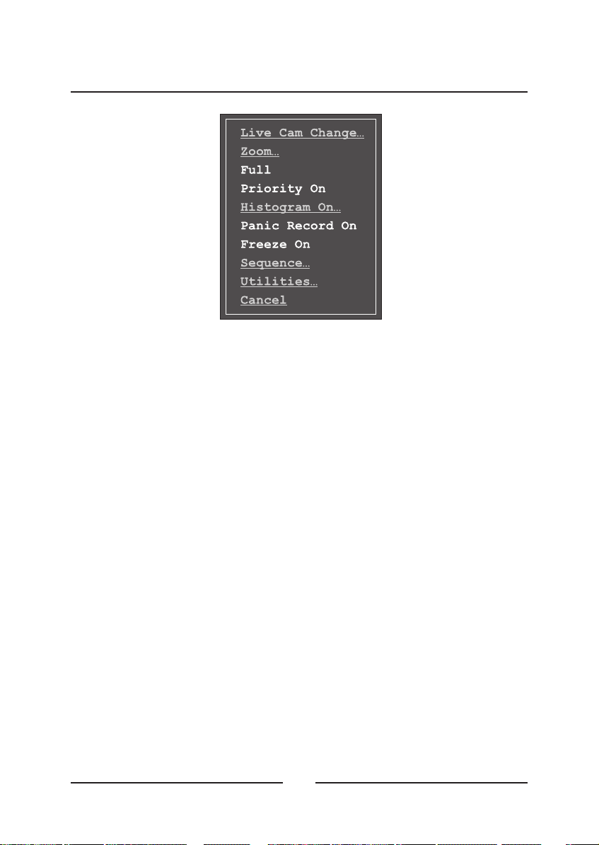
Pop Up Menu
< Figure 47 > Pop Up Menu
Clicking the right mouse button or pressing the SET button cause the
Pop Up menu to appear. There is a list of ten items that can be selected
from the Pop Up menu.
• Live Cam Change… :
• Zoom… :
• Full :
• Priority :
• Histogram :
• Panic Record :
• Freeze :
• Sequence… :
• Utilities… :
• Cancel :
Enters the digital zoom mode.
Displays the selected camera full screen.
Toggles between On and Off.
Toggles between On and Off.
Toggles between On and Off.
Toggles between On and Off.
Enters the Sequence setup mode.
Enters the Utilities mode.
Closes the menu.
Allows you to select the “Live” camera.
58
Page 73

Live Camera Change
< Figure 48 > Live Cam Change menu
The Live Camera Change menu allows you to assign any camera to
active cameo.
ENGLISH
• 1 to 16 :
• Cancel :
Selecting these buttons changes the cameo camera.
Exits the menu without any changes.
59
Page 74

VCR Camera Change
< Figure 49 > VCR Cam Change menu
This menu will appear on the Pop Up menu only when the unit is
Playback mode.
The VCR Camera Change menu allows you to assign any camera to
active cameo.
to Selecting these buttons changes the cameo camera.
• 1 16 :
• Cancel :
Exits the menu without any changes.
60
Page 75
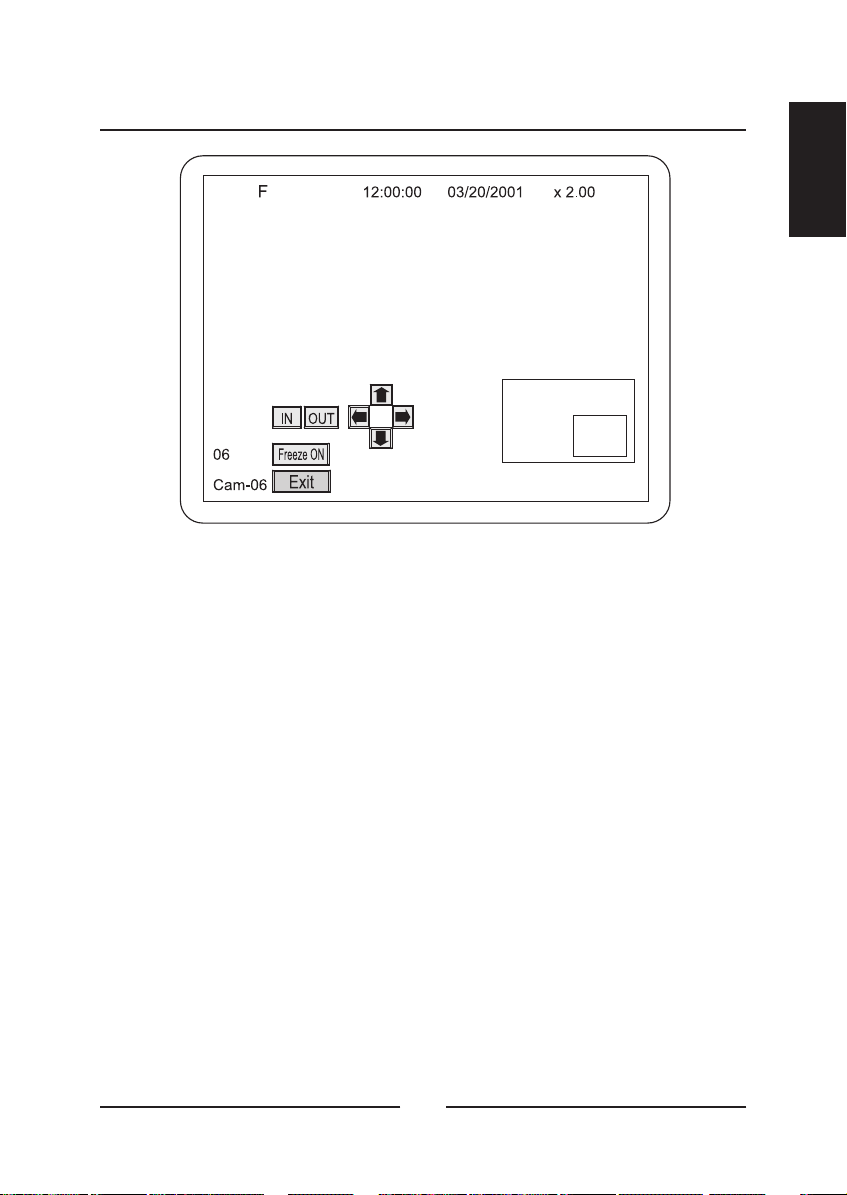
Zoom
< Figure 50 > Zoom Screen.
The digits on the top right of the screen indicate the amount of zoom.
The maximum zoom is 32 times.
The picture insert at the bottom right shows the entire seen with a
rectangle representing the zoomed area.
ENGLISH
• Freeze :
•In:
• Out :
• Arrow buttons :
area left, right, up and down.
• Exit :
Clicking this freezes the image on the screen.
Zooms in (enlarges).
Zooms out.
The arrow buttons are used to move the zoomed
Clicking this button exits the Zoom Mode.
61
Page 76
Full
Clicking Full on the Pop Up menu causes the active camera to display
full screen.
Priority On
When Priority is set to On for a camera, it will display in real time, and
the refresh rate of the other cameras will slow down.
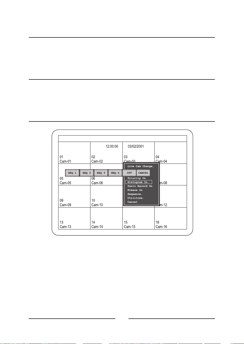
Histogram Equalizer
< Figure 51 > Histogram Equalizer menu bar.
• HEQ1 to 4 : Each Histogram Equalizer button increases image
contrast. HEQ1 has the weakest equalization and HEQ4 has the
strongest equalization.
NOTE : Image noise increases as you use stronger equalization. This
is a property of the equalization algorithm and is does not indicate a
problem with your system.
62
Page 77

••OFF :
image contrast to the original value.
Cancels any Histogram Equalizer settings and returns the
ENGLISH
Cancel :
Cancel exits the menu without any changes.
Panic Record On
When Panic Record is selected only the selected camera is recorded,
and it records in real-time speed.
Freeze On
When Freeze is selected, the image is frozen on the screen until you
reset it.
Sequence
< Figure 52 > Sequence menu.
63
Page 78

The Sequence selection displays the sequence menu.
•
Turn All Cam Seq On :
that are not currently displayed on the screen.
•
Turn User Set Seq On :
defined in the Setup Menu.
•
Cancel :
Exits the menu without any changes.
This selection starts sequencing all cameras
This selection starts a sequence that was
Utilities
User Scrn Chg...
< Figure 54 > User Screen Change menu bar.
< Figure 53 > Utilities Pop Up menu.
64
Page 79
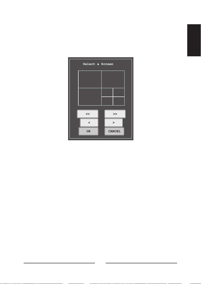
This opens the User Screen Change menu.
This menu allows the user to select one of four displays that were
defined in the Bottom Menu. After selecting one of the UserDef buttons,
the Select a Screen menu appears.
< Figure 55 > Select a Screen menu.
Jumps back through the first screen formats at a time.
<< :
•
ENGLISH
<:
•
>:
•
>> :
•
OK :
•
Cancel :
•
Scrolls back through the screen formats one at a time.
Scrolls forward through the screen formats one at a time.
Jumps forward through the last screen formats at a time.
Confirms the screen format selection.
Exits the menu without any changes.
65
Page 80

OSD Change...
< Figure 56 > OSD Setup screen.
The OSD Setup screen allows you to select what text will be display and
what color the text will be.
Border Line :
•
The border around the images.
Lv Cam Number :
•
Pb Cam Number :
•
Lv Cam Title :
•
Pb Cam Title :
•
Lv Time Date :
•
Pb Time Date :
•
Vloss Text :
•
screen.
The live camera’s number.
The playback camera’s number.
The live camera’s title.
The playback camera’s title.
The live camera’s time and date.
The playback camera’s time and date.
When the video signal is lost, a “V” displays on the
66
Page 81

•
Alarm Text :
•
Motion Text :
screen.
•
Freeze Text :
screen.
•
Sequence Text :
displays on the screen.
When an alarm occurs, an “A” displays on the screen.
When motion is detected, an “M” displays on the
When an image is frozen, an “F” displays on the
ENGLISH
When the multiplexer is in sequence mode, an “S”
•
Motion Box :
displays on the screen.
•
Active Box : When the camera is selected, the active window box
displays.
•
•
Default Color :
default.
•
Available colors :
Cyan and Blue.
•
Exit :
Saves your changes and returns to the live screen.
When motion is detected, a box showing the area
The Spot OSD time, date and camera number, title.Spot OSD :
Clicking this button resets the colors to factory
Black, Gray, White, Red, Green, Yellow, Magenta,
Screen Protect...
The Screen Protect feature allows users to protect there setups against
use or change by unauthorized persons.
Manual Alarm
This feature allows the user to trigger an alarm manually.
Alarm Reset
This feature allows the user to reset an alarm.
67
Page 82

Spot Output...
< Figure 57 > Spot output change screen.
This feature allows the user to assign different cameras to the spot
monitors.
Macro
This feature allows the user to select which macro will play.
User Change...
< Figure 58 >
User Change menu.
68
Page 83

Selecting Supervisor or one of the user numbers opens a password
screen allowing that user to log on. The Supervisor has access to all the
menus and setup features. Users can be assigned different levels of
access. For example some users might not be able to view certain
cameras.
Alarm List...
ENGLISH
< Figure 59 > Alarm History List.
This screen displays a list of alarms. The retains a history of
up to 256 events.
<< :
•
•
•
•
•
Goes to the first page in the history list.
<:
Goes back one page in the history list.
>:
Goes forward one page in the history list.
>> :
Goes to the last page in the history list. (maximum 16 pages)
Transmits all alarm history list to PC.• Print :
Exit :
Returns to the previous screen.
multiplexer
69
Page 84

Playback Format...
< Figure 60 > Select Format menu..
The can play back tapes that were recorded using different
multiplexer
multiplexers. This menu allows you to choose from
DAVE; ULTRAK Legacy Color; ULTRAK Legacy B/W; DM; ROBOT;
KALATEL.
HONEYWELL;
PB Picture Adjust...
This option appears on the Pop Up menu aonly when the unit is in the
Playback Mode. It allows the user to adjust images played back from the
VCR.
The following adjustments have a default setting of 00. The other values
are Min = minimum, -127 to -01 = adjustments below default, 01 to 127 =
adjustments above default, and Max = maximum.
•
Contrast :
••Brightness :
•
Color :
•
Tint :
operation.)
Sharpness :
•
Cancel :
Adjusts color.
Adjusts tint. (Not available when the multiplexer is set for PAL
Closes the menu without any changes.
Adjusts contrast.
Adjusts brightness.
Adjusts sharpness.
70
Page 85

Appendix A
Troubleshooting
Problem Try This
No Video (black screen) Check power connections
No Video (one camera) Check camera power and coaxial cable
No Video (jumbled colors) Make certain multiplexer is set correctly for
your system (NTSC or PAL)
Fuzzy Image (one camera) Check camera focus
Bad Video (one camera) Check the loop through connector.
If a cable is attached, make certain it is
connected to another video device on the
other end.
Wrong Language Change the language in the Setup Menu
Buttons Locked Unlock buttons in Setup Menu.
Recorded Video Rolls Check VCR configuration in Setup Menu.
Use the trigger pulse from the multiplexer
for optimum synchronization with a timelapse VCR.
ENGLISH
Tape Plays Only 4x4 Make certain video cable to the VCR input
is connected to the VCR OUT of the
multiplexer.
Too Many Motion Alarms Adjust sensitivity of motion detection grid.
Adjust size of grid required to activate
motion alarm. Make certain only the area
you want to detect motion is activated.
Motion Not Detected Adjust sensitivity of motion detection grid.
Adjust size of grid required to activate
motion alarm.
Make certain the area you want to detect
motion is activated.
71
Page 86

Appendix B
Connector Pin Outs
The has a 50-pin connector used for alarm input and output,
multiplexer
RS-232 network connections, VCR trigger pulse, and updating the
multiplexer’s firmware. A sub-board is supplied to simplify connections.
See the illustration below for connection details.
< Figure 61 > Connector Sub-Board
72
Page 87

< Figure 62 > RS-485 Connector
NOTE : If termination of RS-485 network is required, short pin 3 and
pin 4.
ENGLISH
73
Page 88

Appendix C
Remote Control
Remote Control for Daisychained Multiplexers
If you are using a computer to control two or more daisy-chained
multiplexers, you need to send a re-address command to select the
multiplexer to control. (Up to 16 multiplexers can be daisy-chained.)
Re-address commands are not printable characters; you need an 8-bit
binary address or hex value to select which daisy-chained multiplexer
you control. If you lose power to one or more multiplexers, you will need
to use the re-address command again to select the correct multiplexer.
HEX RESULTS HEX RESULTS
00 NUL (changes active multiplexer) 09 9 (9th connected multiplexer)
01 1 (1st connected multiplexer) 0A 10 (10th connected multiplexer)
02 2 (2nd connected multiplexer) 0B 11 (11th connected multiplexer)
03 3 (3rd connected multiplexer) 0C 12 (12th connected multiplexer)
04 4 (4th connected multiplexer) 0D 13 (13th connected multiplexer)
05 5 (5th connected multiplexer) 0E 14 (14th connected multiplexer)
06 6 (6th connected multiplexer) 0F 15 (15th connected multiplexer)
07 7 (7th connected multiplexer) 10 16 (16th connected multiplexer)
08 8 (8th connected multiplexer)
<Table1>Re-Address Commands
74
Page 89

Remote Command Set
Simple three-character ASCII commands represent single or
combination front panel button presses on the multiplexer. The effect of
a button press or remote command depends on the multiplexer’s current
status. Check the multiplexer’s current status before issuing a remote
command. Because this multiplexer has a different front keys from the
old model, some new commands are added to control the multiplexer
correctly.
ENGLISH
ASCII MULTIPLEXER KEY
/PA PALARM /01 Camera 1
/TP VCR /02 Camera 2
/MA MACRO /03 Camera 3
/SX RECORD /04 Camera 4
/FZ FULL /05 Camera 5
/PP PIP /06 Camera 6
/22 2 x 2 /07 Camera 7
/33 3 x 3 /08 Camera 8
/44 4 x 4 /09 Camera 9
/SQ SEQUENCE /10 Camera 10
/2N 2ND /11 Camera 11
/FR FREEZE /12 Camera 12
/ZO ZOOM /13 Camera 13
/ST SET /14 Camera 14
/ES ESC /15 Camera 15
/UP UP /16 Camera 16
/DO DOWN
/LE LEFT
/RI RIGHT
<Table2>Front key emulation commands
ASCII MULTIPLEXER KEY
75
Page 90

Functional remote commands
HEX RESULTS HEX RESULTS
/S1 Panic record (camera 1) /X1 Select camera 1 for display
/S2 Panic record (camera 2) /X2 Select camera 2 for display
/S3 Panic record (camera 3) /X3 Select camera 3 for display
/S4 Panic record (camera 4) /X4 Select camera 4 for display
/S5 Panic record (camera 5) /X5 Select camera 5 for display
/S6 Panic record (camera 6) /X6 Select camera 6 for display
/S7 Panic record (camera 7) /X7 Select camera 7 for display
/S8 Panic record (camera 8) /X8 Select camera 8 for display
/S9 Panic record (camera 9) /X9 Select camera 9 for display
/SA Panic record (camera 10) /XA Select camera 10 for display
/SB Panic record (camera 11) /XB Select camera 11 for display
/SC Panic record (camera 12) /XC Select camera 12 for display
/SD Panic record (camera 13) /XD Select camera 13 for display
/SE Panic record (camera 14) /XE Select camera 14 for display
/SF Panic record (camera 15) /XF Select camera 15 for display
/SG Panic record (camera 16) /XG Select camera 16 for display
/AV Stop panic record /_U Up (press & hold arrow button)
/AF Setup Menu /_D Down (press & hold arrow button)
/AU Factory Reset /_L Left (press & hold arrow button)
/AD Alarm History List /_R Right (press & hold arrow button)
/AL Alarm History List /AR Time/Date OSD ON/OFF
<Table3>Remote commands
76
Page 91

Appendix D
Specifications
Operating Defaults
Display Format 4x4 multi-screen format
Operation Mode Live
Factory Defaults
Date Format US (MM/DD/YY)
Time Format 24-hour
Clock Source Internal clock
Daylight Saving OFF
Camera Access All cameras ON
Cameras to Record All cameras ON
Stack Dwell Time 3 seconds
Sequence Dwell Time 3 Seconds
Alarm Reset Button ON
Alarm Screen Format 4x4
Alarm Dwell Time 03 seconds
Alarm input Polarity NO (Normally Open)
Alarm Output Polarity AH (Active High)
Alarm Buzzer ON
Alarm Screen ON
Alarm Network Relay OFF
Alarm Massage Latch ON
Alarm Recording INT (Interleaving)
Alarm Spot Monitor Output ON
Alarm Hold Time 20 Seconds
Alarm Action Timed Out
Alarm Relay 1&2
Alarm Associated 3 sequential cameras
followed by alarm camera
Motion Alarm Buzzer OFF
Motion Alarm Screen OFF
Motion Alarm Network Relay OFF
Motion Alarm Massage Latch ON
ENGLISH
77
Page 92

Motion Alarm Recording INT (Interleaving)
Motion Alarm Spot Monitor Output OFF
Motion Alarm Action Timed Out
Motion Alarm Relay OFF
Motion Alarm Link OFF
Vloss Buzzer ON
Vloss Screen OFF
Vloss Network Relay OFF
Vloss Massage Latch ON
Vloss Spot Monitor Output ON
Vloss Hold Time 20 Seconds
Manual Alarm Buzzer ON
Manual Alarm Screen ON
Manual Alarm Network Relay OFF
Manual Alarm Massage Latch ON
Manual Alarm Recording INT (Interleaving)
Manual Alarm Spot Monitor Output ON
Manual Alarm Hold Time 20 Seconds
Manual Alarm Action Timed Out
Manual Alarm Relay 1&2
Manual Alarm Associated OFF
Alarm to Macro link OFF
All Motion Detection ON
Motion Detection Timer OFF
Update/Master Update
Normal/Vector Normal
Sensitivity 10
Trigger Size (H x V) 1 x 1
Delay Time 0 Seconds
Motion Hold Time 5 Seconds
Target Grids All Grids ON
VCR Input BNC
External Trigger OFF
Panic Record Buzzer ON
VCR Type Standard VHS
VCR Normal Record Time 2 Hours, 3 Hours (PAL)
VCR Alarm Record Time 2 Hours, 3 Hours (PAL)
78
Page 93

Camera Contrast 00
Camera Brightness 00
Camera Color 00
Camera Tint 00
Language English
Mouse ON
Key Lock OFF
Camera Number Offset OFF
Master/Slave Slave
Network Type RS232
Baud Rate 1200
Unit Address 001
Protocol A
Setup Menu Password OFF
User Change Password OFF
Password Code User1 (1111)
User2 (2222)
User3 (3333)
User4 (4444)
Supervisor (5555)
VCR Picture Adjustment 00
Priority Display OFF
Histogram Equalization OFF
Border Line ON (Black)
Live Camera Number ON (white)
PB Camera Number ON (Blue)
Live Camera Title ON (White)
PB Camera Title ON (Blue)
Live Time, Date ON (White)
PB Time,Date ON (Blue)
Vloss Text ON (White)
Alarm Text ON (White)
Motion Text ON (White)
Freeze Text ON (Red)
Sequence Text ON (White)
Motion Box OFF (Blue)
ENGLISH
79
Page 94

Video format
NTSC/PAL Standard
Video Level
Camera Inputs 1.0Vp-p, 75 Ohms
Camera Outputs 1.0Vp-p, 75 Ohms
Loop through Output 1.0Vp-p, 75 Ohms
VCR Input: Composite 1.0Vp-p, 75 Ohms
VCR Input: S-Video Luma 1.0Vp-p, 75 Ohms
Chroma (burst) 0.286Vp-p, 75 Ohms
Main Output: Composite 1.0Vp-p,75 Ohms
Main Output: S-Video Luma 1.0Vp-p, 75 Ohms
Chroma (burst) 0.286Vp-p, 75 Ohms
Auxiliary Output 1.0Vp-p, 75 Ohms
Main Output Display Formats (live and playback)
Full (digital)
Full (VCR input preview – digital)
Quad
9-way
16-way
“Squish” Horizontal (1/2, 1/3)
“Squish” Vertical (1/2, 1/3)
PIP with 1 inset (any position, 1/3, 1/4)
PIP with 2 insets (any position,1/3, 1/4)
PIP with 3 insets (any position,1/3, 1/4)
PIP with 4 insets (any position,1/3, 1/4)
1+7(3/4x1+1/16 x 7, 4 configurations)
1+5(4/9x1+1/9x5,4configurations)
1+12 (1/4x1+1/16 x 12, 4 configurations)
2+8(1/4x2+1/16 x 8, 4 configurations)
3+4(1/4x3+1/16 x 4, 4 configurations)
Linear Zoom (1X to 32X) with electronic Pan & Tilt
Resolution (pixels x lines)
Sampling NTSC : 720 x 480
720 x 576
PAL :
Full (Active) 648 x 448 (648 x 518)
(10 to 9 down-scaling)
80
Page 95

1/4 Size 324 x 224 (324 x 259)
1/9 Size 216 x 149 (216 x 173)
1/16 Size 162 x 112 (162 x 129)
4/9 Size 432 x 298 (432 x 346)
9/16 Size 486 x 336 (486 x 387)
VCR Out (full) 720 x 480 (720 x 576)
Spot Out analog
Sampling Standard
Y:Cb:Cr CCIR 601 (4:2:2)
Gray Scale 256 levels
Color 16 million (True Color)
Video Memory
Main Display 64Mbit SDRAM
VCR Output 64M/16Mbit SDRAM
Refresh Rate (fields/sec.)
Full 60
PIP format (Main) 60
PIP format (inset) 60
Squish 60
Split format (1_2 cameras) 60
Split format (3-16 cameras) 60/number of cameras
Zoom 60
Spot Out 60
VCR Out (depends on field delay) 60 max
Priority Mode (major) 60
Priority Mode (minor) 30/Number of Cameras
ENGLISH
Display Options
Triplex (Live & Playback at same time)
Full Sequence
Cameo Sequence (any 1 position) Split or PIP mode
Page Sequence (2x2, 3x3) Squish,4-way, 9-way
Freeze All
Freeze One Camera
Camera Assign
Priority Assign (1 cam only)
81
Page 96

Motion Tracking Box
Digital Contrast Enhancer
Motion Detection
Activity Grid (16 x 16 grids)
Activity Detection
Intrusion Detection
Motion Vector Sensing (any direction)
Sensitivity Levels 01-16
Motion Delay Time 0 to 5 Seconds
Motion Hold Time 1 to 99 Seconds
Day & Night Modes (2 setup modes)
Interleaving (VCR Out)
Motion Tracking Box (on screen Setup & Live)
Two-way detecting algorithm Update or Master screen mode
VCR Playback
Multi-format Decoding (via setup) Dedicated Micros, Robot®,
Kalatel (Impac), Pelco™ and
more
Alarm Operation
Alarm Inputs 16 inputs with individual polarity
selection, activated by contact
closure or TTL/CMOS signal
Alarm Outputs relay 2 NO and NC contacts with
shared common, 1.0A and 24VDC
(resistive only)
Alarm Outputs One output per camera,
TTL/CMOS (Active High or Low
selectable)
Alarm Message Display
Associated Alarm Setup Up to 4 cameras
Alarm Dwell Time 1 to 99 Seconds
Alarm Hold Time 1 to 99 Seconds
Alarm Buzzer On/Off
Manual Alarm Activation
82
Page 97

Alarm History Logging 256 events
Alarm History Printout via RS232
Link Alarms to Macro
Link Alarms to VMD
External Alarm Relay Box 16 relays via RS485
On-Screen Display (Main)
Camera Title 24 characters
Time & Date U.S., Asia, European
12/24-hour format
Alarm Message
Motion Message
Video Loss Message
Zoom Mode Message
Freeze Mode Message
Sequence Mode Message
Setup Menu
Camera Number
On-Screen Display (Spot)
Camera Title 24 characters
Time & Date U.S., Asia, European
12/24-hour format
Alarm Message
Video Loss Message
Motion Message
Sequence Mode Message
Camera Number
ENGLISH
Other Features (Internal)
Multi-User Password Protection 1 Supervisor, 4 Users
Keylock
Daylight Saving Time (key press & Menu)
Sequence Dwell Time 1 to 99 Seconds, OFF
Page (Stack) Sequence Dwell Time 1 to 99 Seconds
83
Page 98

Time-lapse VCR Setup (field delay selectable)
2 hr real-time to 960 hr
time-lapse
Video Loss Detection
Factory Reset
Unit ID Number 1 to 255
Picture Adjust (Live, Playback)
Macro (1 per camera)
Macro Scheduler
Camera Number Offset 1 to 256
Multilingual Menu English, German, French,
Italian, Spanish, Polish
Camera Auto Detect
Border Color Select
Record Index List
Panic Record
Flash Memory Upgradable via RS232
Other Features (External Interface)
VCR Trigger Input
Master/Slave TDG via RS485
Master/Slave Setup
PC Software Control via RS232
Remote Control
RS232 (1200 _ 19200 bps) RX/TX
RS485 (1200 _ 19200 bps) RX/TX
Mouse Control
Rear Panel Connectors
Camera Inputs 16 BNC
Loop Out (auto terminating) 16 BNC
Main Monitor Out (CVBS) 1 BNC
Main Monitor OUT (Y/C) 1 4-pin mini DIN
VCR In (CVBS) 1 BNC
VCR In (Y/C) 1 4-pin mini DIN
VCR Out (CVBS) 1 BNC
84
Page 99

VCR Out (Y/C) 1 4-pin mini DIN
Alarm Input/Output Terminal block
RS232 (RX/TX) Terminal block
RS485 (RX/TX) 2 RJ45
Spot (Aux) Out 4 BNC
Power 2.1mm pin type; female
P/S2 Mouse Port 1 5-pin mini DIN
Front Panel Controls
Manual Alarm
VCR
Macro
Panic Record
Full
PIP
2x2
3x3
4x4
Sequence
2nd
Freeze
Zoom
Set
Esc
Cameras 1 to 16
Cursor (up, down, right, left)
ENGLISH
Power Requirements
DC 12V 3A
Power Adapter
100 - 240V~, 50/60Hz
85
Page 100

Dimensions
Unit Size 17"W x 1.73"H x 12.2"D
432W x 44H x 310D mm
Shipping Size 26"W x 4.8"H x 15.5"D
660W x 123H x 393D mm
Weight
Unit Weight 5.3 lbs (2.4 Kgs)
Shipping Weight 9.5 lbs (4.3 Kgs)
Operating Environment
Ambient Temperature 32° to 95° F (0° to 35° C)
Ambient Humidity 10% to 90% non-condensing
86
 Loading...