

Page 1
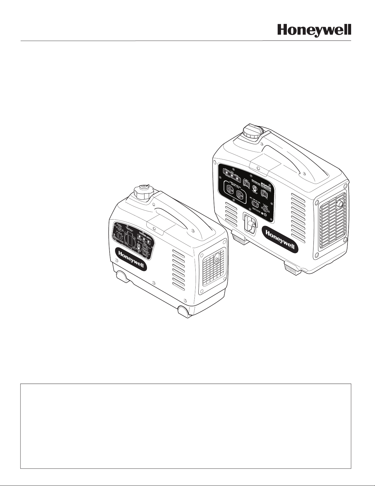
Inverter Generator
Owner’s Manual
Guide D’Utilisation
Manual del Propietario
HW1000i
HW2000i
For product inquires or support, please visit www.honeywellgenerators.com or
call toll-free at 1-888-HWHELP1 (494-3571).
Pour obtenir des renseignements sur les produits ou pour du soutien technique,
visitez notre site à l’adresse www.honeywellgenerators.com (en anglais seulement)
ou composez notre numéro sans frais 1-888-HWHELP1 (494-3571).
Si tiene preguntas acerca de los productos o requiere de asistencia, visite
www.honeywellgenerators.com o llame gratis al 1-888-HWHELP1 (494-3571).
Page 2
Congratulations on owning a Honeywell inverter generator!
Model Number:
HW2000i Phase: 1
Part Number:
101440A Frequency: 60Hz
AC/DC Voltage:
120V/12V Engine RPM: 5000
Power Output:
2.0kW Fuel: Gasoline
Max. Ambient Temp.:
40
o
C
Insulation Class: F
Serial Number:
p/n 101627A
245453
Northshore Power Systems, LLC
Milwaukee, WI 53212 USA
WARNING
This manual contains important instructions for operating this generator. For your safety, and the
safety of others, be sure to read this manual thoroughly before operating the generator. Failure to
properly follow all instructions and precautions can cause you and others to be seriously hurt or
killed.
Please use the spaces provided below to record important information about your generator. You may be asked to
provide this information should you require product service or support.
Identification information specific to your generator (model number and serial number) can be found on the generator nameplate.
Northshore Power Systems, LLC
4425 N. Port Washington Rd., Suite 105
Milwaukee, WI 53212-1082 USA
TEL 1-888-HWHELP1 (494-3571)
www.honeywellgenerators.com
Date of Purchase:
Store/Dealer Purchased From:
Generator Model Number:
Generator Serial Number:
© 2009 Northshore Power Systems, LLC
The Honeywell Trademark is used under license from
Honeywell International Inc.
Honeywell International Inc. makes no representations or
warranties with respect to this product.
Page 3
PRODUCT REGISTRATION
1 - PERSONAL INFORMATION
2 - PRODUCT INFORMATION
FIRST NAME
LAST NAME
CHECK HERE TO RECEIVE ANNUAL MAINTENANCE REMINDERS AND SPECIAL OFFERS FROM HONEYWELL
GENERATORS
CHECK HERE TO RECEIVE INFORMATION FROM OTHER COMPANIES VIA EMAIL, UNDERSTANDING YOUR
EMAIL ADDRESS MAY BE SHARED OR COMBINED WITH INFORMATION FROM OTHER SOURCES
DATE OF PURCHASE:
MM DD YYYY
//
*MODEL NUMBER:
*SERIAL NUMBER (18-digits):
PURCHASE LOCATION:
IN-STORE
ONLINE
STORE NAME:
PURCHASE PRICE: $___________.00
FEATURES INFLUENCING PRODUCT PURCHASE:
BRAND REPUTATION EASE OF USE
PORTABILITY SIZE / WEIGHT
POWER RATING STYLE/APPEARANCE
PRICE WARRANTY
HOW DID YOU BECOME AWARE OF THIS PRODUCT?
IN-STORE RADIO/TV
INTERNET STORE CIRCULAR
PRINT WORD OF MOUTH
OTHER BRANDS CONSIDERED WHEN SHOPPING
FOR THIS PRODUCT:
PRIMARY USE FOR PRODUCT:
TOOL POWER
RECREATION POWER
EMERGENCY POWER
PRIMARY LOCATION FOR PRODUCT USE:
HOME
WORK
TYPE OF WORK, IF PRODUCT BEING USED FOR
PROFESSION:
WHAT OTHER TYPE OF POWER EQUIPMENT ARE
YOU INTERESTED IN PURCHASING IN THE FUTURE?
WHO DECIDED TO PURCHASE THIS PRODUCT?
STREET ADDRESS
CITY, STATE, ZIP
COUNTRY
PHONE
EMAIL
*Found on nameplate of generator
To register your product, please complete the information below and mail to the address at the end of the form or register
online at www.honeywellgenerators.com. 18-digit serial number must be completed in order for warranty to be acti-
vated.
Page 4
3 - DEMOGRAPHIC INFORMATION
GENDER:
MALE
FEMALE
MARITAL STATUS:
MARRIED
SINGLE
DATE OF BIRTH:
MM DD YYYY
//
INCLUDING YOURSELF, HOW MANY PEOPLE LIVE IN
YOUR HOUSEHOLD:
NUMBER OF CHILDREN UNDER 18 LIVING IN YOUR
HOUSEHOLD:
PRIMARY RESIDENCE:
OWN
RENT
EDUCATION:
SOME HIGH SCHOOL
HIGH SCHOOL DIPLOMA
COLLEGE DEGREE
GRADUATE DEGREE
THANK YOU FOR REGISTERING YOUR PRODUCT. THE INFORMATION YOU PROVIDED MAY BE USED
FOR MARKETING PURPOSES IN ORDER TO OFFER YOU VARIOUS PRODUCT INFORMATION AND
OFFERS.
CHECK HERE IF YOU DO NOT WISH TO BE CONTACTED ABOUT SPECIAL OFFERS.
PLEASE RETURN THIS FORM TO THE FOLLOWING ADDRESS:
Northshore Power Systems, LLC
4425 N Port Washington Road
Suite 105
Milwaukee, WI 53212-1082
PLEASE MAIL THIS FORM IN A SEALED ENVELOPE. DO NOT STAPLE.
HOUSEHOLD INCOME:
LESS THAN $15,000 $100,000 - $124,999
$15,000 - $29,999 $125,000 - $149,999
$30,000 - $49,999 $150,000 - $174,999
$50,000 - $79,999 $175,000 - $199,999
$80,000 - $99,999 $200,000 OR OVER
PRIMARY METHOD OF PURCHASING HOUSEHOLD
ITEMS:
IN-STORE
ONLINE
TV
MAIL ORDER
TYPES OF CREDIT CARDS HELD BY HOUSEHOLD
MEMBERS:
VISA / MASTERCARD
DISCOVER
AMERICAN EXPRESS
GAS / RETAIL
OTHER
NONE
HOUSEHOLD INTERESTS:
HOME IMPROVEMENT
AUTOMOTIVE WORK
CAMPING
OTHER
Page 5

CONTENTS
IMPORTANT SAFETY RULES ............................................................................................ 1
Safety Messages .........................................................................................................................................1
Location of Important Labels .......................................................................................................................3
GETTING STARTED ......................................................................................................... 5
Package Checklist .......................................................................................................................................5
Record Generator Information .....................................................................................................................5
Grounding the Generator .............................................................................................................................6
Using Generator for Back-up Power ............................................................................................................6
COMPONENTS ................................................................................................................. 7
Accessories .................................................................................................................................................7
Front and Back View ...................................................................................................................................8
OPERATION ................................................................................................................... 11
Generator Location ....................................................................................................................................11
Preparing for Operation .............................................................................................................................11
Starting Generator ..................................................................................................................................... 12
AC Operation ............................................................................................................................................. 14
Stopping Generator ...................................................................................................................................14
Low Oil Protection .....................................................................................................................................14
High-Altitude Operation .............................................................................................................................14
Powering Appliances .................................................................................................................................15
Appliance Wattage Information ................................................................................................................. 15
MAINTENANCE .............................................................................................................. 17
Maintenance Schedule .............................................................................................................................. 17
Engine Oil ..................................................................................................................................................18
Engine Fuel ...............................................................................................................................................21
Cleaning Fuel Strainer ...............................................................................................................................22
Air Filter Maintenance ................................................................................................................................23
Cleaning Spark Arrestor Screen ................................................................................................................ 24
Spark Plug Service ....................................................................................................................................25
Transporting Generator ............................................................................................................................. 26
Storing Generator ...................................................................................................................................... 26
TROUBLESHOOTING .................................................................................................... 27
SPECIFICATIONS AND WIRING DIAGRAMS ............................................................... 29
WARRANTIES ................................................................................................................ 33
NORTHSHORE POWER SYSTEMS CONSUMER LIMITED WARRANTY ............................................. 33
NORTHSHORE POWER SYSTEMS EMISSIONS CONTROL WARRANTY ...........................................34
INDEX .............................................................................................................................. 37
MAINTENANCE PARTS ................................................................................................. 39
HW1000i / HW2000i Inverter Generator Owner’s Manual www.honeywellgenerators.com i
Page 6

THIS PAGE INTENTIONALLY LEFT BLANK
ii www.honeywellgenerators.com HW1000i / HW2000i Inverter Generator Owner’s Manual
Page 7
SAVE THESE INSTRUCTIONS
NOTE:
DANGER
WARNING
CAUTION
NOTICE
+
WARNING
DANGER
IMPORTANT SAFETY RULES
ANYONE using or servicing this generator must read, understand, and follow all safety and operation instructions provided in the product manual. Failure to closely follow these instructions can result in circumstances leading to death,
serious injury, and property damage.
Since there are many variations in the circumstances surrounding the installation, operation, service, and maintenance of this generator, we cannot possibly anticipate or
provide advice or safety messages to cover every situation.
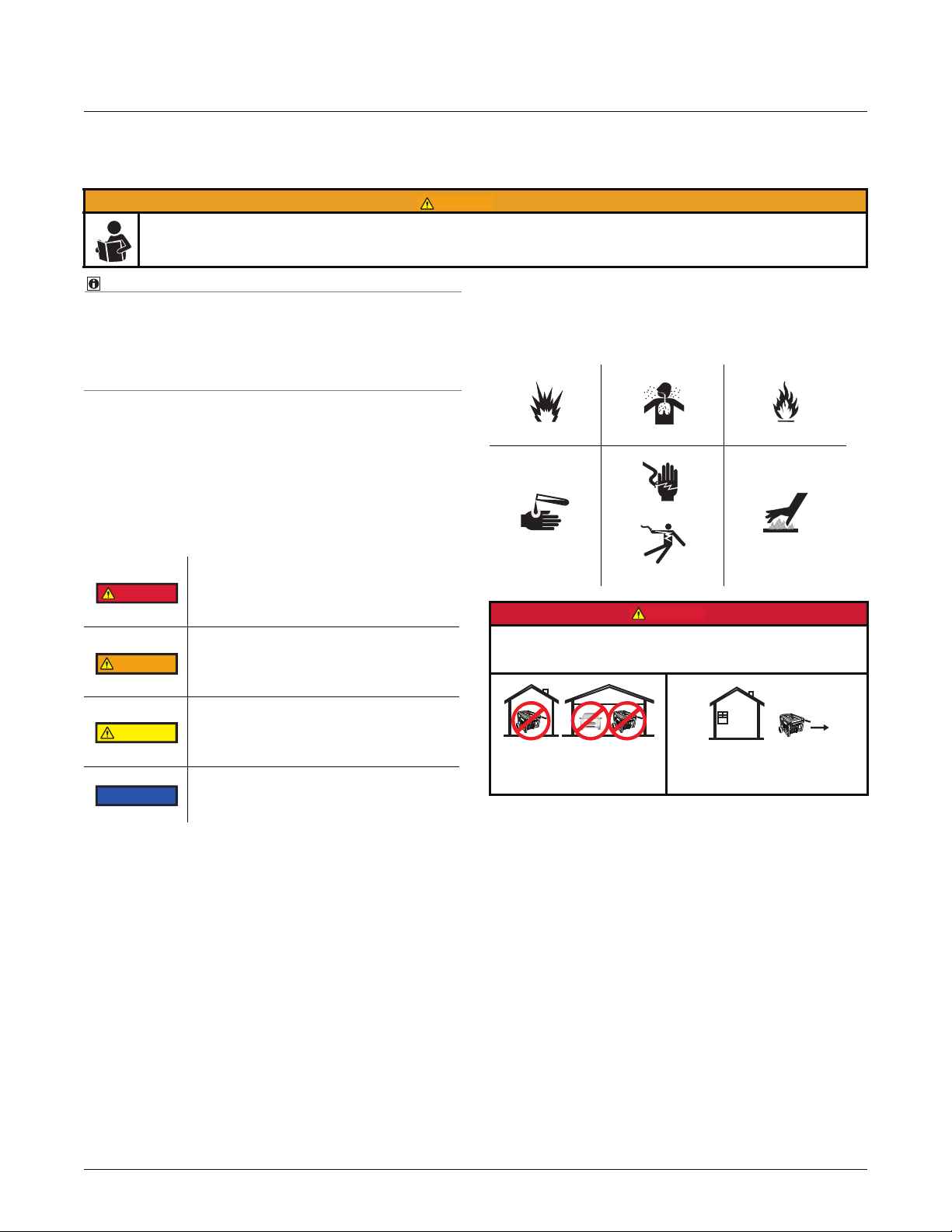
Hazard Symbols and Meanings
In addition to the signal words, the following symbols may
be used to draw your attention to specific types of haz-
ards.
Safety Messages
Signal Words
Safety messages are provided throughout this manual to
help prevent personal injury and equipment damage. All
safety messages are introduced by a signal word indicating the hazard level.
Indicates an imminently hazardous situation which, if not avoided, will result in
death or serious injury to the operator or
to bystanders.
Indicates a potentially hazardous situation which, if not avoided, could result in
death or serious injury to the operator or
to bystanders.
Indicates a potentially hazardous situation which, if not avoided, may result in
moderate or minor injury to the operator
or to bystanders.
Indicates a situation which, if not avoided,
may result in damage to the generator
components.
Explosion
Chemical burn
Using a generator indoors CAN KILL YOU IN MINUTES.
Generator exhaust contains carbon monoxide. This is a poison you cannot see or smell.
NEVER use inside a home
or garage, EVEN IF doors
and windows are open.
Tox i c f u m e s
Electrical shock
Only use OUTSIDE and far
away from windows, doors, and
vents.
Fire
Hot surface
HW1000i / HW2000i Inverter Generator Owner’s Manual www.honeywellgenerators.com 1
Page 8
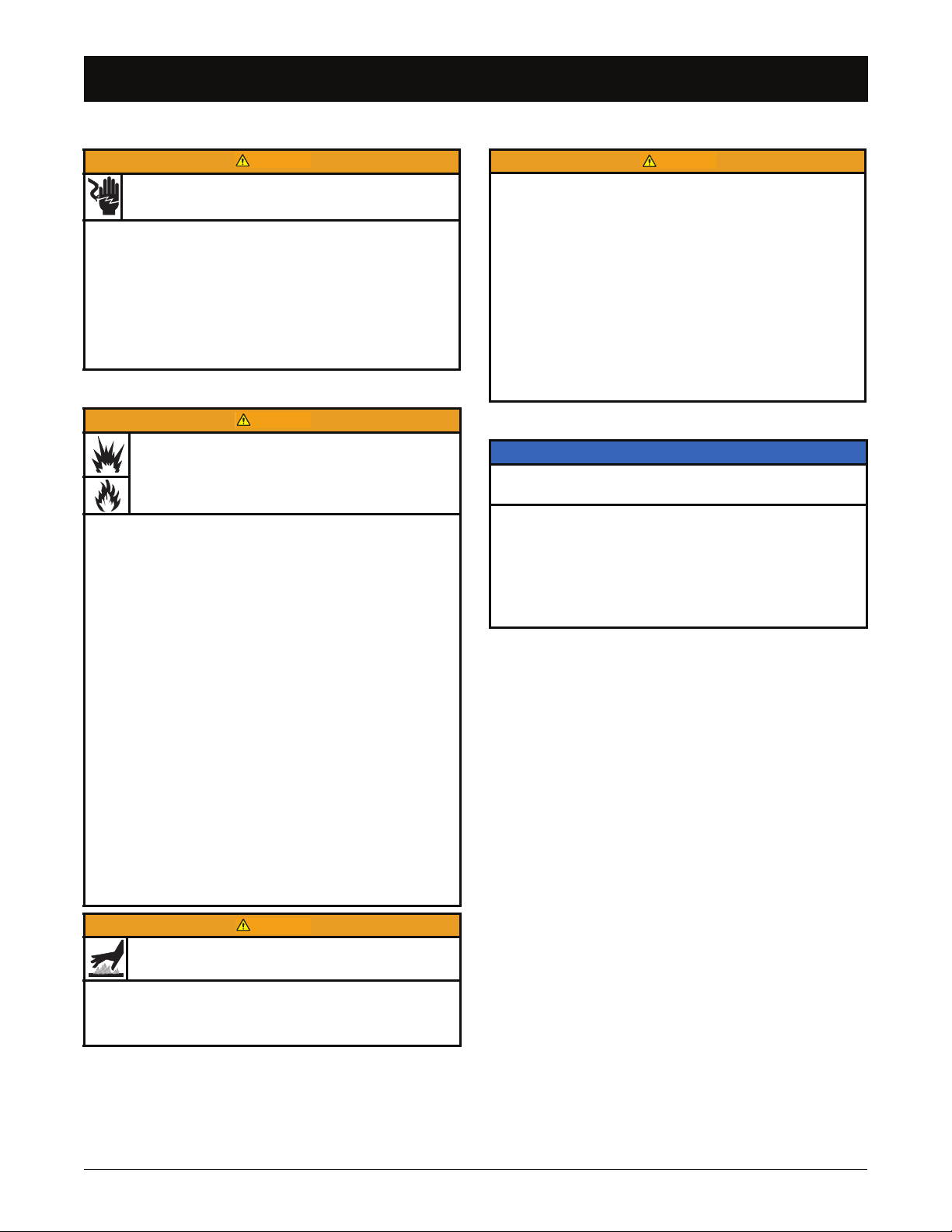
Safety Messages
WARNING
WARNING
WARNING
WARNING
Safety Messages
Electric Shock Hazards
Generators produce powerful voltage that can cause
death or great physical harm.
• NEVER touch bare wires or receptacles.
• NEVER use generator with electrical cords that are
worn, frayed, bare, or otherwise damaged.
• NEVER operate generator in rain or snow, or when
the generator is set on wet surface.
• Keep the generator out of reach of children, pets,
and untrained people.
Fire and Burn Hazards
Fuel and its vapors are extremely flammable and
explosive under certain conditions.
• Refuel generator only outdoors, in a well-ventilated
area.
• NEVER enclose the generator in any structure.
• Keep generator at least 6 feet (2 meters) away from
buildings, other equipment, and combustible materials during operation.
• NEVER fill fuel tank while the engine is running.
Turn generator OFF and allow to cool before filling
with fuel.
• NEVER smoke or allow flames or sparks near the
generator or where gasoline is stored.
• NEVER overfill the fuel tank (there should be no
fuel in the filler neck). After refueling, make sure the
tank cap is closed properly and securely.
• Be careful not to spill fuel when refueling. Spilled
fuel or fuel vapor may ignite. If any fuel is spilled, be
sure the area is dry before starting the engine.
• Avoid repeated or prolonged contact with skin or
breathing of vapor.
Medical and Life Support Uses
• In case of emergency, call 911 immediately.
• NEVER use this product to power life support
devices or life support appliances.
• NEVER use this product to power medical devices
or medical appliances.
• Inform your electricity provider immediately if you
or anyone in your household depends on electrical
equipment to live.
• Inform your electrical provider immediately if a loss
of power would cause you or anyone in your
household to experience a medical emergency.
Generator Damage Hazards
NOTICE
Improper treatment or misuse of generator can cause permanent damage.
• NEVER modify generator in any way.
•
NEVER tamper with governed speed. Generator supplies correct rated frequency and voltage when running at governed speed.
• Damage to generator caused by misuse or modifi-
cation is not covered under Warranty.
The muffler becomes very hot during operation and
remains hot for a while after stopping the engine.
• NEVER touch hot surfaces and avoid hot gases.
• Let engine cool before storing the generator
indoors.
2 www.honeywellgenerators.com HW1000i / HW2000i Inverter Generator Owner’s Manual
Page 9
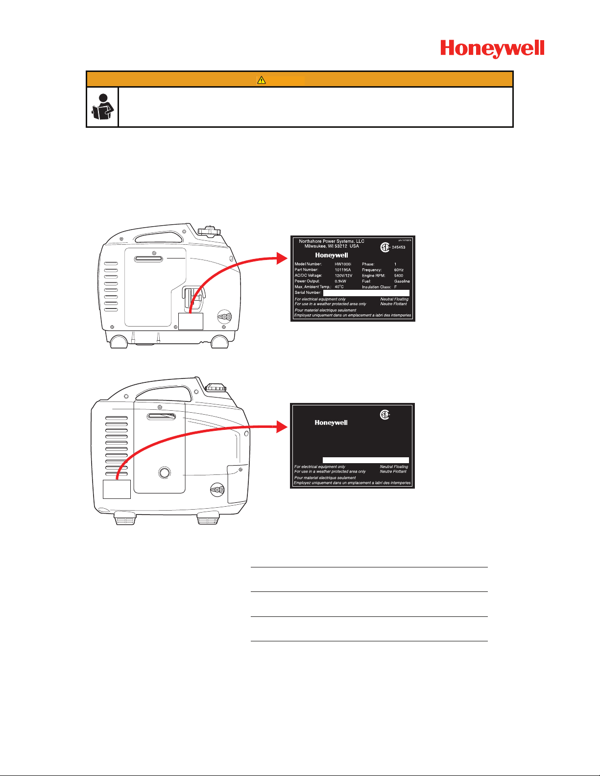
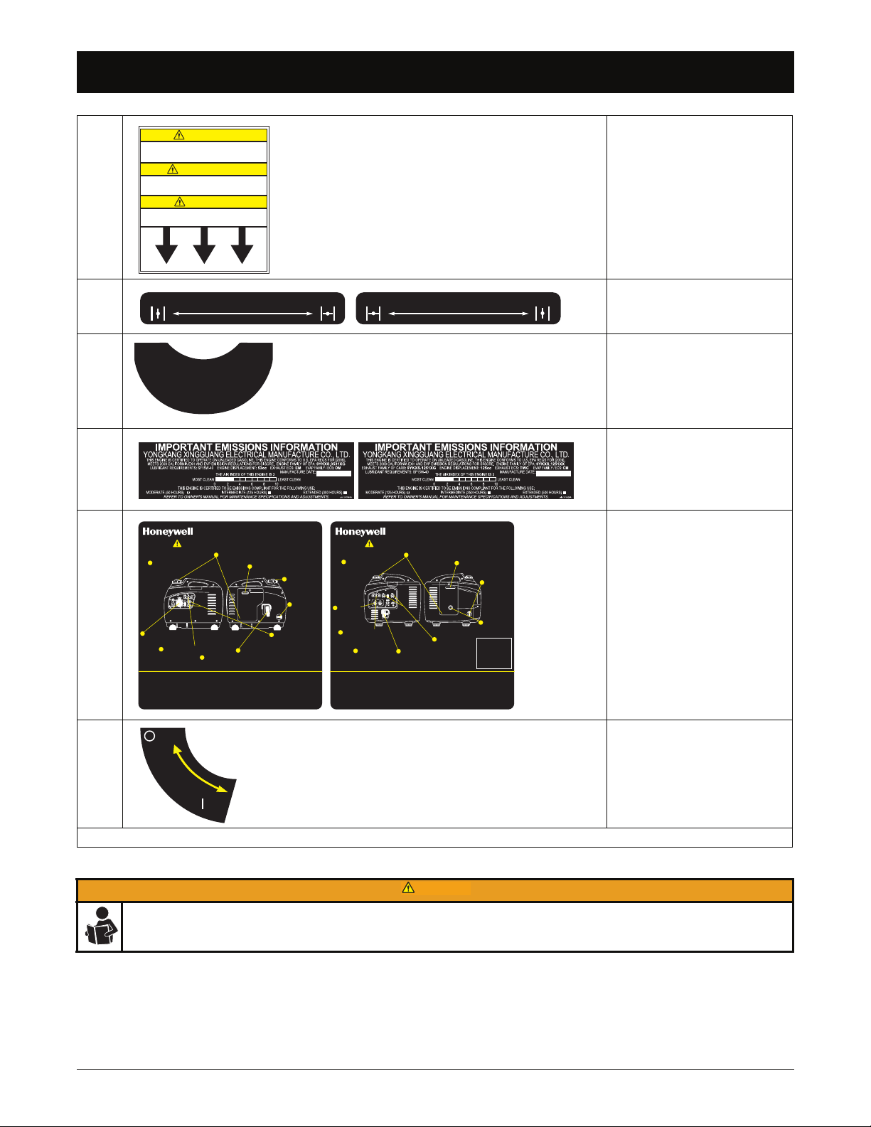
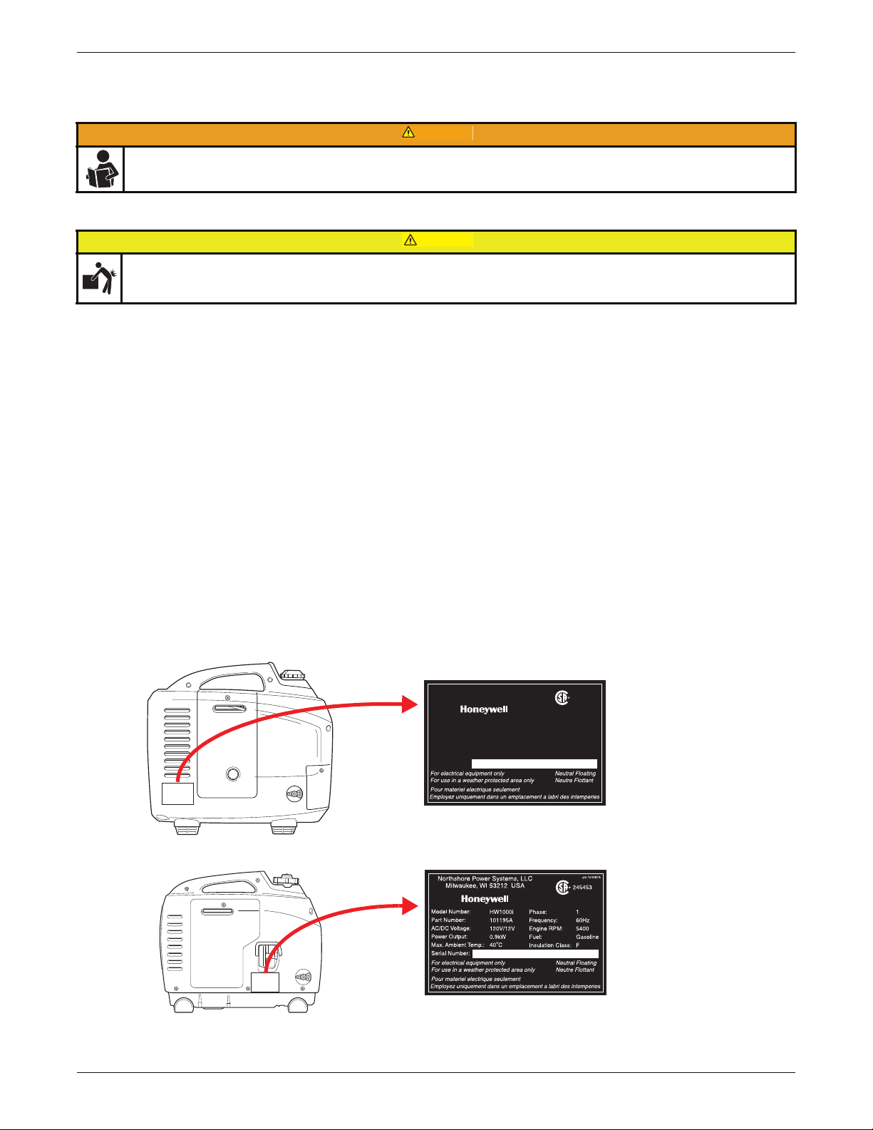
Location of Important Labels
C
B
A
A
A
D
G
H
F
C
B
A
D
H
F
G
E
DANGER
Using a generator indoors CAN KILL YOU IN MINUTES.
Generator exhaust contains carbon monoxide.
This is a poison you cannot see or smell.
NEVER use inside a home
or garage, EVEN IF doors
and windows are open.
Only use OUTSIDE and
far away from windows,
doors, and vents.
DANGER
L'utilisation d’une génératrice à l’intérieur peut
CAUSER LA MORT EN QUELQUES MINUTES.
L’échappement de la génératrice dégage
du monoxyde de carbone.
Ce produit ne doit JAMAIS être utilisé à
l’intérieur d’une maison ou d’un garage,
MÊME SI les portes et les fenêtres sont ouvertes.
Utilisez SEULEMENT à l’extérieur
et tenez éloigné des fenêtres,
portes et prises d’air ouvertes.
p
/
n
:
1
0
1
5
9
1
A
Location of Important Labels
Location of Important Labels
Your generator has several labels which provide important safety and maintenance information. Samples of these labels are
provided below. Should any of these labels become illegible or damaged, call 1-888-HWHELP1 (494-3571) for replacements.
FIGURE 1: HW1000i Model Label Locations
FIGURE 2: HW2000i Model Label Locations
A 101589A
B 101591A
HW1000i / HW2000i Inverter Generator Owner’s Manual www.honeywellgenerators.com 3
PELIGRO
Utilizar un generador en el interior
PUEDE MATARLO EN CUESTION DE MINUTOS.
Los gases de escape del generador contienen monóxido
de carbono. Este es un veneno que no se ve, ni huele.
NUNCA lo utilice dentro del hogar
ni del garaje AUNQUE estén
abiertas las puertas y las ventanas.
Utilícelo siempre AFUERA
y lejos de ventanas,
puertas y ventilas.
PRODUCT LABEL PART NUMBER
Page 10
Location of Important Labels
Entrée d’air sur le bas de l’inverseur.
MAINTENEZ LA ZONE CLAIRE.
Air intake located on bottom of
inverter. DO NOT BLOCK.
CAUTION
ATTENTION
El aire entra en el fondo de la
unidad. NO BLOQUEE.
CUIDADO
p/n: 101588A
OFF ON
CHOKE
p/n 101605A
ON OFF
CHOKE
p/n 101610A
TO START
PRIME ENGINE 3 TO 5X
INITIAL OR DRY START
PRIME ENGINE 30 TO 50X
p/n 101726A
2
8
9
10
3
6
7
1
5
12 3
4
4
MOVE INVERTER OUTSIDE.
DÉPLACEZ L'ONDULATEUR À
L’EXTÉRIEUR.
MUEVA EL INVERSOR HACIA
AFUERA.
CHECK OIL & FUEL LEVEL.
VÉRIFIEZ LE NIVEAU D'HUILE ET DE CARBURANT.
REVISE LOS NIVELES DE ACEITE Y COMBUSTIBLE.
TURN FUEL VALVE ON.
OUVREZ LE ROBINET
DE CARBURANT.
MUEVA LA VÁLVULA
DE COMBUSTIBLE
A ENCENDIDO.
MOVE CHOKE TO ON.
METTEZ L’ÉTRANGLEUR EN POSITION ON.
MUEVA EL CONTROL DE
AHOGO A ENCENDIDO.
MOVE ENGINE SWITCH TO RUN
AND EFFICIENCY MODE TO OFF.
METTEZ LE COMMUTATEUR DU
MOTEUR EN POSITION RUN ET
LE MODE D'EFFICACITÉ EN
POSITION OFF.
MUEVA EL CONTROL DE MOTOR
A EJECUTAR Y EL MODO DE
EFICACIA A APAGADO.
PULL RECOIL TO START.
TIREZ LE LANCEUR À
RAPPEL POUR
DÉMARRER.
JALE LA CUERDA DE
REBOBINADO PARA
ARRANCAR.
MOVE CHOKE TO OFF.
METTEZ L’ÉTRANGLEUR
EN POSITION OFF.
MUEVA EL CONTROL DE
AHOGO A APAGADO.
CHECK READY LIGHT ON.
ASSUREZ-VOUS QUE LE VOYANT
LUMINEUX EST ALLUMÉ.
ESPÉRESE HASTA QUE SE
ENCIENDA LA LUZ LISTA.
PLUG IN POWER CORDS.
BRANCHEZ LES CORDONS
D’ALIMENTATION.
CONECTE LOS CABLES.
ALL USERS MUST READ AND UNDERSTAND OWNER’S MANUAL!
TOUS LES UTILISATEURS DOIVENT LIRE ET COMPRENDRE LE GUIDE D'UTILISATION!
TODOS LOS USUARIOS DEBEN LEER Y COMPRENDER EL MANUAL OPERACIÓN!
!
FOR 24-HOUR STARTING INSTRUCTIONS
1-888-RECOIL-8 (732-6458)
p/n 101596A
UNPLUG POWER CORDS.
DÉBRANCHEZ LES CORDONS
D’ALIMENTATION.
DESENCHUFE LOS CABLES.
STOPPING INSTRUCTIONS INSTRUCTIONS D’ARRÊT INSTRUCTIONS PARA DETENER
MOVE ENGINE SWITCH TO STOP.
METTEZ LE COMMUTATEUR DU
MOTEUR EN POSITION D’ARRÊT.
MUEVA EL CONTROL DE MOTOR A
DETENER.
TURN FUEL VALVE OFF.
FERMEZ LE ROBINET DE CARBURANT.
MUEVA EL RESPIRADERO DE
COMBUSTIBLE A EJECUTAR.
SMART START INSTRUCTIONS
HW1000i
TURN FUEL VENT ON.
OUVREZ LA MISE À L’AIR
LIBRE CARBURANT.
MUEVA EL RESPIRADERO
DE COMBUSTIBLE A
ENCENDIDO.
TURN FUEL VENT OFF.
FERMEZ LA MISE À L’AIR
LIBRE CARBURANT.
MUEVA LA VÁLVULA
DE COMBUSTIBLE
A APAGADO.
2
8
9
10
3
6
7
1
4
12 3
MOVE INVERTER OUTSIDE.
DÉPLACEZ L'ONDULATEUR À
L’EXTÉRIEUR.
MUEVA EL INVERSOR HACIA
AFUERA.
CHECK OIL & FUEL LEVEL.
VÉRIFIEZ LE NIVEAU D'HUILE ET DE CARBURANT.
REVISE LOS NIVELES DE ACEITE Y
COMBUSTIBLE.
TURN FUEL VALVE ON.
OUVREZ LE ROBINET
DE CARBURANT.
MUEVA LA VÁLVULA
DE COMBUSTIBLE
A ENCENDIDO.
MOVE CHOKE TO ON.
METTEZ L’ÉTRANGLEUR EN POSITION ON.
MUEVA EL CONTROL DE AHOGO A
ENCENDIDO.
PULL RECOIL TO START.
TIREZ LE LANCEUR À
RAPPEL POUR DÉMARRER.
JALE LA CUERDA DE
REBOBINADO PARA
ARRANCAR.
MOVE CHOKE TO OFF.
METTEZ L’ÉTRANGLEUR
EN POSITION OFF.
MUEVA EL CONTROL DE
AHOGO A APAGADO.
CHECK READY LIGHT ON.
ASSUREZ-VOUS QUE LE VOYANT
LUMINEUX EST ALLUMÉ.
ESPÉRESE HASTA QUE SE
ENCIENDA LA LUZ LISTA.
PLUG IN POWER
CORDS.
BRANCHEZ LES
CORDONS
D’ALIMENTATION.
CONECTE LOS
CABLES.
ALL USERS MUST READ AND UNDERSTAND OWNER’S MANUAL!
TOUS LES UTILISATEURS DOIVENT LIRE ET COMPRENDRE LE GUIDE D'UTILISATION!
TODOS LOS USUARIOS DEBEN LEER Y COMPRENDER EL MANUAL OPERACIÓN!
!
p/n 101597A
UNPLUG POWER CORDS.
DÉBRANCHEZ LES CORDONS
D’ALIMENTATION.
DESENCHUFE LOS CABLES.
STOPPING INSTRUCTIONS INSTRUCTIONS D’ARRÊT INSTRUCTIONS PARA DETENER
MOVE ENGINE SWITCH TO STOP.
METTEZ LE COMMUTATEUR DU
MOTEUR EN POSITION D’ARRÊT.
MUEVA EL CONTROL DE MOTOR A
DETENER.
TURN FUEL VALVE OFF.
FERMEZ LA MISE À L’AIR
LIBRE CARBURANT.
MUEVA LA VÁLVULA DE
COMBUSTIBLE A APAGADO.
MOVE ENGINE SWITCH
TO RUN AND EFFICIENCY
MODE TO OFF.
METTEZ LE COMMUTATEUR
DU MOTEUR EN POSITION
RUN ET LE MODE D'EFFICACITÉ EN POSITION OFF.
MUEVA EL CONTROL DE
MOTOR A EJECUTAR Y EL
MODO DE EFICACIA A
APAGADO.
SMART START INSTRUCTIONS
HW2000i
FOR 24-HOUR STARTING INSTRUCTIONS
1-888-RECOIL-8 (732-6458)
5
PRIME ENGINE 3X.
INJECTEZ DU
CARBURANT 3X.
EMPUJE EL BULBO
TRES VECES.
IF TANK LOW OR RUN TO
EMPTY, PRIME 30 TO 50X.
SI LE RÉSERVOIR EST BAS
OU SE VIDE, INJECTEZ DU
CARBURANT 30 À 50X.
SI EL TANQUE BAJO O EL
FUNCIONAMIENTO A
VACÍO, EMPUJE EL BULBO
30 - 50 VECES.
OFF
ON
FUEL
p/n 101592A
WARNING
Location of Important Labels
C 101588A
D
101605A (HW1000i Model)
101610A (HW2000i Model)
E 101726A (HW2000i Model)
101590A (HW1000i Model)
F
101628A (HW2000i Model)
101596A* (HW1000i Model)
G
101597A* (HW2000i Model)
H 101592A
TABLE 1. Safety Labels
* The Smart Start instruction label is NOT intended to replace information provided in this Owner’s Manual. Be sure to
thoroughly read and understand all information provided in the Owner’s Manual before operating the generator. Failure
4 www.honeywellgenerators.com HW1000i / HW2000i Inverter Generator Owner’s Manual
to properly follow all instructions and precautions can cause you and others to be seriously injured or killed.
Page 11
GETTING STARTED
WARNING
CAUTION
p/n 101627A
245453
Northshore Power Systems, LLC
Milwaukee, WI 53212 USA
Use the information in this section to get your generator ready for operation.
ANYONE using this generator must read, understand, and follow all safety and operation instructions provided in the
product manual. Failure to closely follow these instructions can result in circumstances leading to death, serious injury,
and property damage.
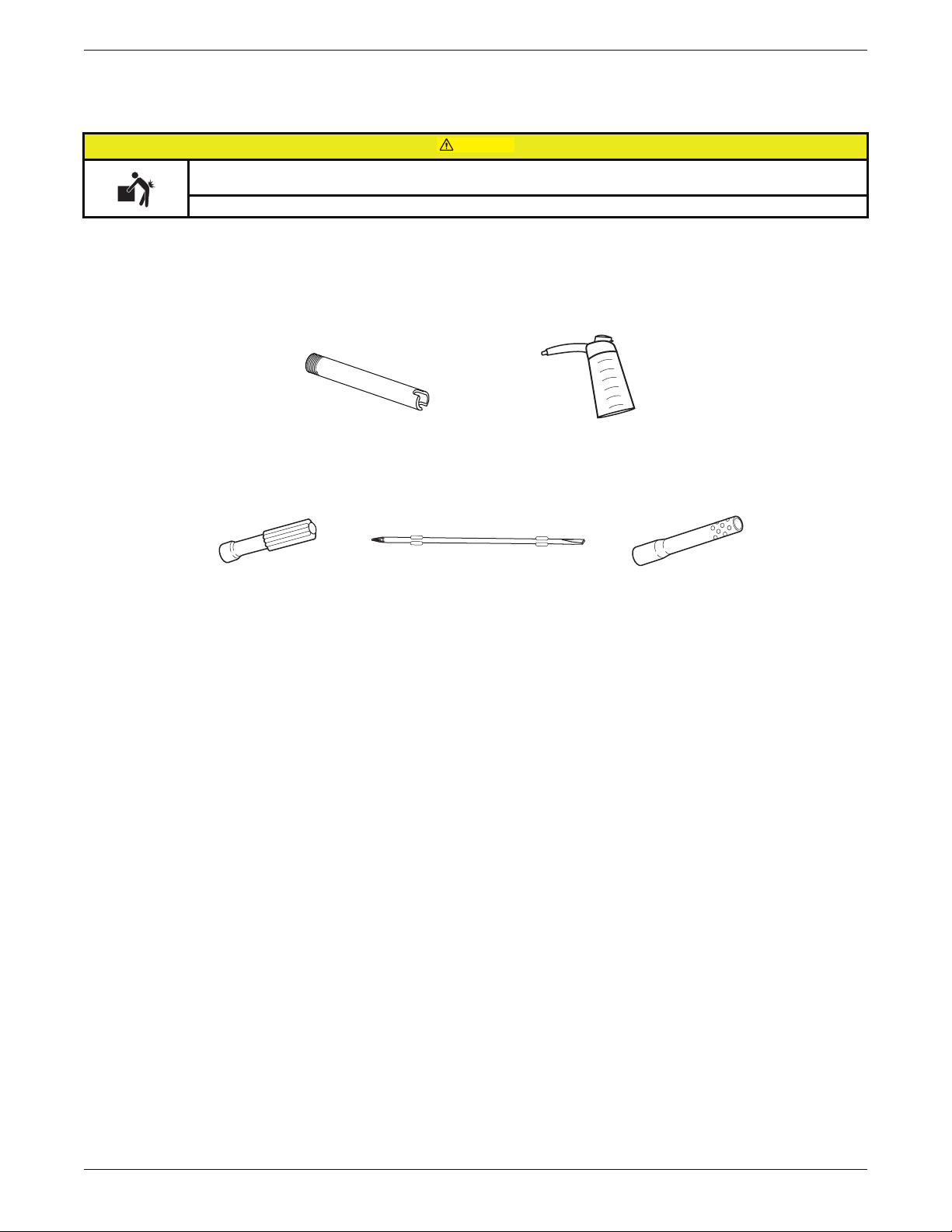
Package Checklist
Generator is heavy! Obtain assistance to lift the generator to avoid back or other bodily injury.
Verify that all of the following items are included in the generator package:
Inverter Generator
Owner’s Manual
Oil Fill Container
Oil Drain Pipe
Spark Plug Wrench
Screwdriver Handle
Screwdriver Universal Bit
Inspect for Damage
Carefully inspect generator for any damage that may have occurred during shipment. If loss or damage is noted after
opening, separate damaged materials and call 1-888-HWHELP1 (494-3571).
Record Generator Information
Write down the identification information specific to your generator in the spaces provided on the inside cover of this
Owner’s Manual. This information is located on the generator nameplate (see illustration below).
Model Number:
Part Number:
AC/DC Voltage:
Power Output:
Max. Ambient Temp.:
Serial Number:
HW2000i Phase: 1
101440A Frequency: 60Hz
120V/12V Engine RPM: 5000
2.0kW Fuel: Gasoline
o
40
C
Insulation Class: F
HW1000i / HW2000i Inverter Generator Owner’s Manual www.honeywellgenerators.com 5
FIGURE 3: Generator Nameplate Location
Page 12
Grounding the Generator
NOTE:
WARNING
DANGER
Grounding the Generator
Grounding the Generator
Generator must be grounded to prevent electrical
shock from faulty appliances.
• Before using generator, consult a qualified electrician,
electrical inspector, or local agency having jurisdiction
for local codes or ordinances that apply to the intended
use of generator.
The National Electric Code requires the generator to be
connected to an earth ground. Before using the generator,
connect a copper wire (minimum 14 AWG) from the
ground terminal (see Figure 4) to an earth ground. Consult a licensed electrician for proper grounding methods.
Using Generator for Back-up Power
Before connecting to a building’s electrical system, consult
your local utility company or a qualified electrician.
Improper connections to a building's electrical system can
be deadly.
Electrical current from generator can feedback into
utility lines. Such feedback may electrocute utility
company workers or others who contact utility lines
during a power outage.
Electrical current can feedback into generator. When
utility power is restored, generator may explode,
burn, or cause fires in building's electrical system.
The National Electric Code requires any generator connected to a building’s electrical wiring utilize a transfer
switch installed by a licensed electrician.
What is a transfer switch?
A transfer switch is a device that allows switching
from utility power to emergency generator power.
The transfer switch is either a manual switch, an
automatic switch, or a combination of manual and
automatic. During a power outage, the transfer
switch isolates emergency circuits from the utility
line, allowing for efficient operation of the generator
without back-feeding into utility power.
FIGURE 4: Ground Terminal (HW2000i model illustrated)
The system ground is not connected to the AC neutral
wire. If using a receptacle tester, it will not show the same
ground circuit condition as for a home receptacle.
Special Requirements
There may be Federal or State Occupational Safety and
Health Administration (OSHA) regulations, local codes, or
ordinances that apply to the intended use of generator.
Please consult a qualified electrician, electrical inspector,
or the local agency having jurisdiction.
• In some areas, generators are required to be regis-
tered with local utility companies.
• If generator is used at a construction site, there may
be additional regulations which must be observed.
6 www.honeywellgenerators.com HW1000i / HW2000i Inverter Generator Owner’s Manual
Page 13
COMPONENTS
CAUTION
Use information provided in this section to become familiar with your generator’s components.
The information below is provided for reference only. Refer to “OPERATION” on page 11 for instructions on
operating generator.
Generator is heavy! Obtain assistance to lift the generator to avoid back or other bodily injury.
Accessories
Oil Drain Pipe
Screwdriver Handle
FIGURE 5: Inverter Accessories
Oil Fill Container
Screwdriver Universal Bit
Spark Plug Wrench
HW1000i / HW2000i Inverter Generator Owner’s Manual www.honeywellgenerators.com 7
Page 14
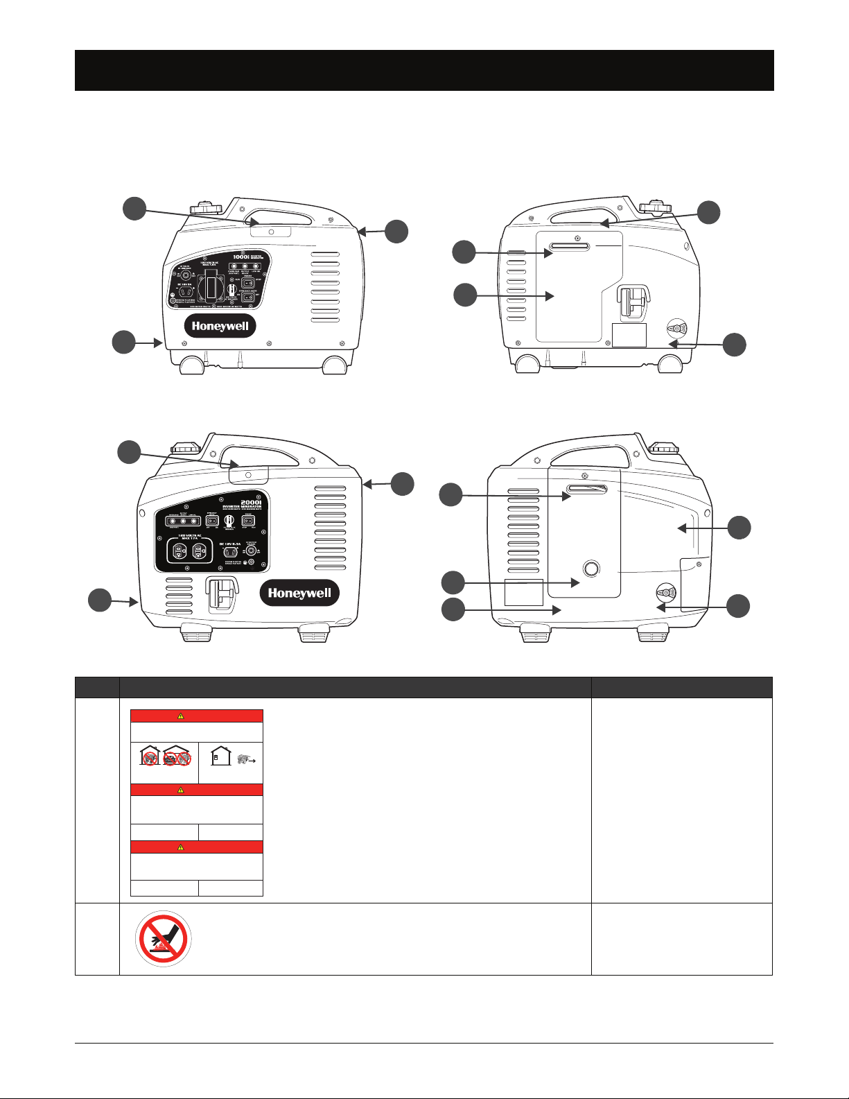
Front and Back View
A
D
B
C
2
4
7
8
6
1
5
3
G
E
F
H
J
WARNING
CAUTION
Set Tripped
DC
AC
Front and Back View
Front and Back View
HW1000i Model
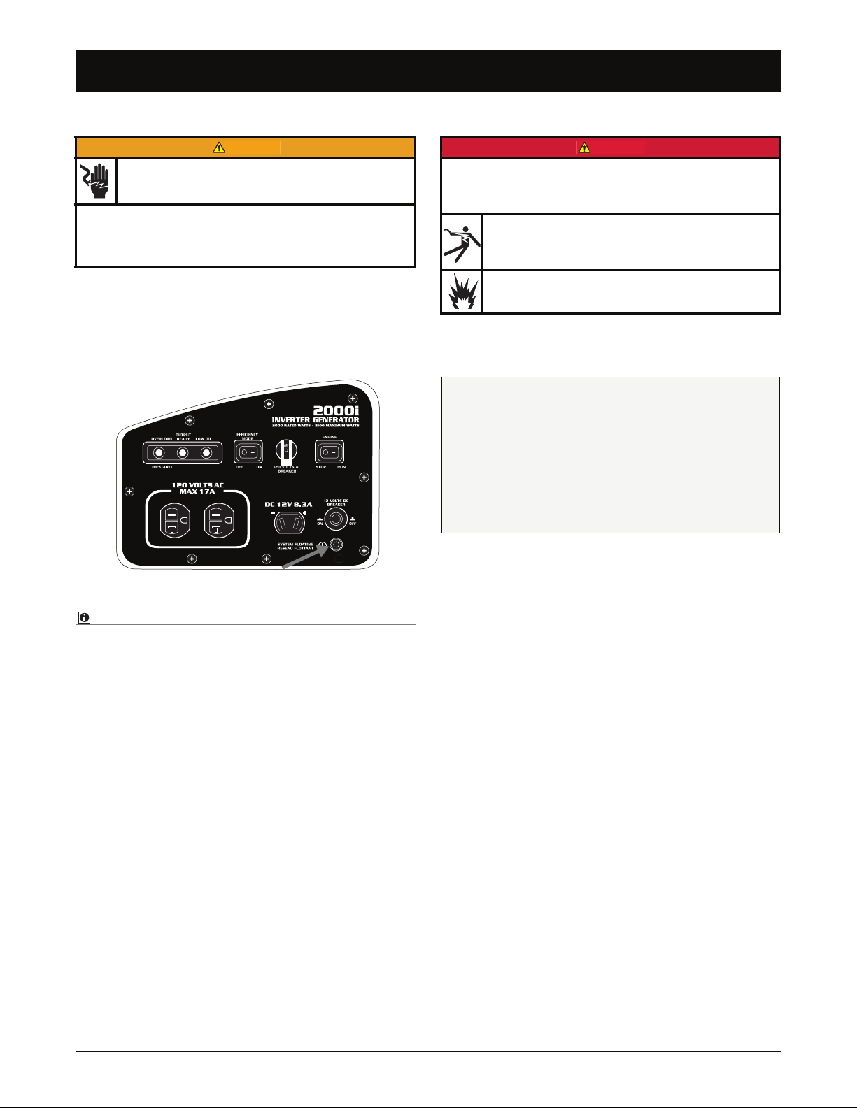
A—Control Panel
1. Outlets
125VAC outlet(s) (NEMA 5-15R [HW1000i model] and NEMA
5-20R [HW2000i model]) to connect 120V appliances to generator for power.
DC outlet ranges from 12 to 18 volts and is unregulated. This
outlet should not be used for battery charging.
NEVER use unapproved DC cables as this can
result in circumstances leading to death, serious
injury, and property damage. ALWAYS use Honeywell DC accessory cables (sold separately) available
from a Honeywell dealer.
Breakers
3.
Protect circuits from damage caused by
overload or short-circuit by stopping flow
of electricity from generator to the appliance. If there is no power at outlets, see
“Troubleshooting” on page 27.
4.
Overload Indicator Light
Illuminates red when the generator is overloaded or if there is
a short circuit in a connected appliance. Turn the generator
off immediately and determine the reason for the overload.
5.
Output Indicator Light
Illuminates green when the generator is running under normal operating conditions.
Ground Terminal
2.
Connects generator to ground wire for grounding protection.
6.
Oil Alert Indicator Light
Illuminates red when low oil conditions are present and the
generator is running (
or while recoil is pulled). The engine
will automatically stop to prevent generator damage.
Generator must be grounded to prevent electrical
shock from faulty appliances. See page 6.
8 www.honeywellgenerators.com HW1000i / HW2000i Inverter Generator Owner’s Manual
Page 15

HW2000i Model
A
D
E
B
C
2
8
4
7
6
1
5
3
G
F
H
I
J
WARNING
Front and Back View
Front and Back View
7. Engine Control Switch
Turns the engine ON or OFF.
8.
Efficiency Mode Switch
When Efficiency Mode is ON, the engine speed will automatically adjust based on the connected load, resulting in better
fuel consumption and less noise.
In DC operation, set the Efficiency Mode Switch to the
OFF position.
B—Top Maintenance Cover
Provides access to the engine spark plug.
C—Muffler
Provides outlet for engine exhaust.
Muffler reaches temperatures that can cause serious
burns if touched. NEVER touch hot surfaces.
D—Case Feet
Provides stability to the generator.
E—Recoil Starter Handle
Starts engine.
F—Back Maintenance Cover
Provides access to air filter, fuel filter, and oil fill cap.
G—Fuel Cap
Provides a secure seal on fuel tank. The HW1000i model has
a vented fuel cap.
H—Fuel Valve
Controls flow of fuel from fuel tank to carburetor.
I— Primer Bulb (HW2000i model only)
Provides primer fuel to start engine.
J—Choke Control
Controls choke valve. Choke control must be in the ON posi-
tion when starting a cold engine.
HW1000i / HW2000i Inverter Generator Owner’s Manual www.honeywellgenerators.com 9
Page 16

THIS PAGE INTENTIONALLY LEFT BLANK
10 www.honeywellgenerators.com HW1000i / HW2000i Inverter Generator Owner’s Manual
Page 17

OPERATION
DANGER
+
WARNING
WARNING
WARNING
DANGER
Generator Location
When deciding on the location to place your generator,
keep in mind the following safety rules:
Depressed areas such as construction foundations,
pools, or any low-lying areas, can cause carbon
monoxide to accumulate. Inhalation of carbon monoxide can kill you in minutes.
• NEVER use generator inside homes, garages,
crawl spaces, sheds, or similar enclosed
spaces. Use generator only outdoors and far
away from windows, doors, and vents.
If generator is placed on an uneven or flexible surface, generator could tilt or overturn, causing fuel to
spill from gas tank. Spilled fuel could ignite.
• Place generator on firm, level surface and avoid
loose sand or snow. If generator is tilted or
overturned, fuel spillage may result. Also, if
generator is overturned or sinks into a soft surface, sand, dirt, or water may enter generator.
NEVER operate generator in rain or snow, or
when the generator is set on wet surface.
Keep generator at least 6 feet (2 meters) away
from buildings, other equipment, and combustible
materials during operation.
Preparing for Operation
Using a generator indoors CAN KILL YOU IN MINUTES.
Generator exhaust contains carbon monoxide. This is a poison you cannot see or smell.
NEVER use inside a home
or garage, EVEN IF doors
and windows are open.
Before starting generator, complete the following preparation tasks:
Be sure generator is placed outdoors in a well
ventilated area.
Check/add engine oil— IMPORTANT! BEFORE
STARTING GENERATOR, FILL WITH ENGINE OIL.
See page 18 -p. 21 for instructions on filling, checking, and changing oil.
Check/add fuel—ADD FUEL. See page 22.
Check air filter—See “Air Filter Maintenance” on
page 23.
Be sure ground terminal is properly connected to
earth ground—See “Grounding the Generator” on
page 6.
Check extension cords—be sure cords are:
In good condition.
Rated for outdoor use and match amperage and
voltage ratings of generator outlet.
Equipped with proper plugs that contain grounding
blades.
Only use OUTSIDE and far
away from windows, doors, and
vents.
HW1000i / HW2000i Inverter Generator Owner’s Manual www.honeywellgenerators.com 11
Page 18

Starting Generator
NOTE:
NOTE:
WARNING
p/n 101592A
OFF
ON
Starting Generator
Starting Generator
Before starting generator, be sure to thoroughly read
all information provided in this Owner’s Manual.
NOTICE
It is very important to maintain the proper level of engine oil
to keep the engine in good running condition.
• Check engine oil level prior to each use.
IMPORTANT! BEFORE STARTING GENERATOR, FILL
WITH ENGINE OIL.
Starting generator with appliances connected can cause
permanent damage to appliances.
• NEVER start generator with electrical appliances
plugged in and turned on.
• Do not move the generator while it is running.
1. Fill the fuel tank and check oil is to appropriate level.
The generator starts more easily with a full fuel tank.
2. Place the generator outside on a flat surface free of
debris to prevent blocking the air intake vents in the
bottom of the generator.
4. Move the choke to the ON position.
Place the choke in the OFF position when the HW1000i
has a warm engine.
5. Set the efficiency mode switch to the OFF position.
FIGURE 7: Efficiency Mode Switch
6. Turn the fuel valve to the ON position.
OFF
FUEL
ON
FIGURE 8: Fuel Valve — ON position
ON
7. Press the engine control switch to the RUN position.
FIGURE 6: Air Intake - DO NOT BLOCK
NOTICE
Blocking the air flow may cause damage to the generator.
3. Connect a ground wire to the generator (see “Ground-
ing the Generator” on page 6).
FIGURE 9: Engine Control Switch
8. HW1000i Model Only: Turn the fuel cap vent to the
ON position.
FIGURE 10: Fuel Cap Vent — ON position
12 www.honeywellgenerators.com HW1000i / HW2000i Inverter Generator Owner’s Manual
Page 19

Starting Generator
NOTE:
NOTE:
Starting Generator
HW2000i Model Only: Depress the primer bulb 3
times to supply fuel to start the engine.
FIGURE 11: Prime Engine
INITIAL START: Depress the primer bulb 30-50 times to
prime the fuel lines.
If the generator has a low fuel tank or has been run to
empty before being refilled, the primer bulb may need to
be depressed 30-50 times to prime the fuel lines.
12. After starting, confirm the output ready indicator light
is green and stays on.
FIGURE 13: Output Ready Indicator Light (HW1000i model)
13. Allow the engine to run continuously and warm up
before connecting any appliance.
NOTICE
If the engine stops and will not restart, check the engine oil
level before troubleshooting in other areas.
9. While securing the generator with one hand, grip the
recoil starter handle and pull slowly until you feel
slight resistance. (HW2000i model illustrated)
FIGURE 12: Recoil Starter Handle
10. Apply 1 to 4 swift pulls to start the engine, carefully
returning the recoil starter handle to the original position.
NOTICE
To prevent damage to the generator, do not allow the recoil
starter handle to snap back against the engine.
11. After the engine starts, let run for 2-5 seconds and
then slowly move the choke to the OFF position.
HW1000i / HW2000i Inverter Generator Owner’s Manual www.honeywellgenerators.com 13
Page 20

AC Operation
NOTE:
NOTE:
CAUTION
AC Operation
AC Operation
DC power and AC power can be used at the same time.
1. Turn off and unplug all equipment to be plugged into
the generator.
2. Start the generator (see “Starting Generator” on
page 12).
3. Plug in the appliance and monitor the overload indica-
tor light. If the overload indicator illuminates longer
than 4 seconds, STOP THE ENGINE IMMEDIATELY.
Do not restart generator until the reason for the over-
load or appliance short circuit is corrected.
Low Oil Protection
The oil alert system is designed to avoid engine damage
from not enough oil in the crankcase. The oil alert system
will stop the engine automatically before the crankcase oil
gets below the safety line. The engine will not restart until
the required amount of engine oil is added.
Oil alert indicator light only illuminates while generator is
running or while recoil is pulled.
FIGURE 16: Oil Alert Indicator Light
FIGURE 14: Overload Indicator Light (HW2000i model)
Substantial overloading that continuously lights the overload
indicator light may damage the generator. Marginal overloading that temporarily lights the overload indicator light may
shorten the service life of the generator.
If appliance begins to operate abnormally, becomes sluggish, or stops suddenly, turn it OFF immediately. Disconnect
appliance and determine whether problem is appliance, or if
rated load capacity of generator has been exceeded.
4. Set the efficiency mode switch to the ON position.
FIGURE 15: Efficiency Mode Switch
Stopping Generator
In an emergency:
Press the engine control switch to the STOP position.
In normal use:
1. Turn OFF any connected appliances and unplug any
connected power cords.
2. Allow the generator to run for 2-3 minutes.
3. Press the engine control switch to the STOP position.
4. Turn the fuel valve to the OFF position.
5. Turn the fuel cap vent to the OFF position (HW1000i
model only).
High-Altitude Operation
At high altitudes, standard carburetor air-fuel mixture will
be excessively rich. Performance will decrease and fuel
consumption will increase.
High-altitude performance can be improved by installing a
smaller diameter main fuel jet in the carburetor and then
readjusting the pilot screws. If you always operate the
engine at altitudes higher than 5000 feet (1500 meters)
above sea level, have an authorized generator dealer perform this carburetor modification.
Even with suitable carburetor jetting, engine horsepower
will decrease approximately 3.5% for each 1000 foot (300
meters) increase in altitude above sea level. The effect of
altitude on horsepower will be greater than this if no carburetor modification is made.
NOTICE
If engine jetted for high altitude is used at lower altitude, lean
air fuel mixture will reduce performance and may over-heat
and seriously damage the engine.
14 www.honeywellgenerators.com HW1000i / HW2000i Inverter Generator Owner’s Manual
Page 21

Powering Appliances
NOTE:
WARNING
WARNING
CAUTION
Powering Appliances
Powering Appliances
In this manual, the term “appliance” refers to any electrical device that can be connected to generator for power.
NOTICE
NEVER start generator with electrical appliances plugged in
and turned on.
Faulty appliances and power cords can result in electrical shock.
• Before attempting to power an appliance, be sure
generator has been properly grounded, and that
appliance and power cord are in good working order.
• Keep the generator away from other electric cables or
wires including commercial power supply lines.
• Do not use generator for any purpose other than its
intended use.
• Do not parallel connect generators or lengthen the
exhaust pipe.
• Do not connect generator to any household circuit,
otherwise it may destroy generator or home electric
equipment.
disconnect appliance(s), wait a few minutes, and
then push to reset the circuit breaker.
• Pay attention to appliance operation: If appliance
begins to operate abnormally, becomes sluggish, or
stops suddenly, turn it OFF immediately. Disconnect
the appliance and determine whether the problem is
the appliance, or if rated load capacity of the generator has been exceeded.
• Use suitable extension cords: If using an exten-
sion cord to connect appliances to the generator,
use only UL-listed, three-prong extension cords. Be
sure the extension cord is the proper size (wiregauge) to handle the electrical load that will be
plugged into it.
Appliance Wattage Information
Use table below as a guide to determine how much power
you will need to run appliances using generator.
The values provided in following table are estimates only.
• ALWAYS verify actual wattage requirements for appliance you will be powering. Check labels inside or on
the back of appliance, refer to appliance operating
manuals, or contact appliance manufacturer.
Medical and Life Support Uses
• In case of emergency, call 911 immediately.
• Never use this product to power life support
devices or life support appliances.
• Never use this product to power medical devices or
medical appliances.
• Inform your electricity provider immediately if you
or anyone in your household depends on electrical
equipment to live.
• Inform your electrical provider immediately if a loss
of power would cause you or anyone in your
household to experience a medical emergency.
• Plan carefully: Before using the generator to power
appliances, take time to add power ratings (wattage)
of each appliance and verify that total wattage does
not exceed rated output of generator. Power rating
information can usually be found on an appliance’s
product label, stamped inside, or on the back of the
appliance. See Table 2 for a listing of average appliance wattage requirements.
• NEVER overload: Circuit breakers will stop the flow
of electricity between the generator and appliance if
the generator is overloaded. This will be indicated
by a “tripped” breaker. If this happens, power off and
Appliance Typical Running Watts
Air Conditioner, Central* 3500
Air Conditioner, Window* 500-1440
Aquarium 50-1210
Clock Radio 10
Coffee Maker 900-1200
Computer, CPU -
Awake / Asleep
Computer, Monitor -
Awake / Asleep
Computer, Laptop 50
Dehumidifier* 785
Dishwasher*
Dryer, Electric 1800-5000
Electric Blanket
(Single/Double)
Fan, Ceiling* 65-175
Fan, Window* 55-250
Furnace*
Hair Dryer 1200-1875
Heater, Portable 750-1500
120 / 30 or less
150 / 30 or less
1200-2400 (using drying
feature greatly increases
energy consumption)
60 / 100
*
750
HW1000i / HW2000i Inverter Generator Owner’s Manual www.honeywellgenerators.com 15
Page 22

Appliance Wattage Information
NOTE:
CAUTION
Appliance Wattage Information
Appliance Typical Running Watts
Iron 1000-1800
Microwave Oven 750-1100
Radio, Stereo 70-400
Refrigerator, Frost-free, 16
Cubic Feet*
Sump Pump, 1/2 hp* 2150
Sump Pump, 1/3 hp* 2300
Television
• 19"
• 27"
• 36"
• 53"-61" Projection
• Flat Screen
Toaster 800-1400
Toaster Oven 1225
Vacuum Cleaner* 1000-1440
VCR/DVD 17-21 / 20-25
Washing Machine 350-500
Water Heater, 40 gal 4500-5500
Water Pump, Deep Well* 250-1100
TABLE 2. Typical Appliance Running Wattages
725
65-110
113
133
170
120
*Allow up to three times normal running watts for starting this appliance.
Appliances in grey require a higher wattage output than
the inverter generator will produce.
NOTICE
Starting appliances that have motors requires more power.
Examples of motorized appliances include refrigerators,
water pumps, and furnace blowers. Be sure the appliance
power rating does not exceed that of the generator.
Do not run power cords under carpet, rugs, or other materials where heat might build up or cord damage may go unnoticed.
16 www.honeywellgenerators.com HW1000i / HW2000i Inverter Generator Owner’s Manual
Page 23

MAINTENANCE
DANGER
WARNING
WARNING
Maintenance Schedule
Periodic maintenance and adjustment are necessary to keep the generator in good operating condition. Perform service and
inspection at the intervals shown in the Generator Maintenance Schedule (see Table 3).
Using a generator indoors CAN KILL YOU IN MINUTES.
Generator exhaust contains carbon monoxide. This is a poison you cannot see or smell.
Accidental starting of generator can cause severe injury or
death. Before performing maintenance, disconnect spark
plug cap from spark plug.
Improper maintenance, or failure to correct a problem before
operation, can cause a malfunction in which you can be seri-
ously hurt or killed. Always follow inspection and mainteNEVER use inside a home
or garage, EVEN IF doors
and windows are open.
Only use OUTSIDE and far
away from windows, doors, and
vents.
• Shut off engine before performing any maintenance. If
engine must be run, be sure area is well ventilated.
nance recommendations and schedules in this owner's
manual.
NOTICE
The maintenance schedule applies to normal operating con-
ditions. If you operate generator under severe conditions,
NOTICE
Maintenance, replacement, or repair of the emission
control devices and systems may be performed by any
non-road engine repair establishment or individual.
MAINTENANCE TASK
Before
each use
First month
or 25 hours
of use
such as sustained high-load or high-temperature, or use it in
unusually wet or dusty conditions, consult your servicing
dealer for recommendations applicable to your individual
needs and use.
FREQUENCY
Every 3
months or
50 hours of
use
*
Every 4
months or
62.5 hours
of use
Every 6
months or
100 hours of
use
year or
200 hours
Fill fuel tank X
Check engine oil level X
Check air cleaner X
Clean air cleaner
†
X
Change engine oil (HW1000i) X
Change engine oil (HW2000i) X
Check/clean spark plug X
Clean spark arrestor
‡
X
Check/adjust valve clearance
Clean fuel tank and strainer X**
Check fuel line Every 2 years (replace if necessary)**
TABLE 3. Generator Maintenance Schedule
* Perform at every indicated month or operating hour interval, whichever comes first.
† Clean more often when using generator in dusty areas.
‡ HW2000i model only.
** It is recommended that this maintenance task be performed by a service dealer.
Every
of use
**
X
HW1000i / HW2000i Inverter Generator Owner’s Manual www.honeywellgenerators.com 17
Page 24

Engine Oil
WARNING
Engine Oil
Engine Oil
NOTICE
Engine oil is a major factor affecting engine performance
and service life. Non-detergent and 2-stroke engine oils will
damage engine and are not recommended.
• Be sure to use engine oils specified under “Engine Oil
Recommendations.”
It is very important to maintain proper level of engine oil to
keep engine in good running condition.
• Check engine oil level prior to each use. Refill engine
oil if oil level is low.
Engine Oil Recommendations
Use 4-stroke oil, or equivalent high detergent, premium
quality motor oil certified to meet or exceed U.S. automobile manufacturer's requirements for API Performance
Class SF or better. SAE 15W-40 is recommended for general, all-temperature use.
15W-40
4. Remove the oil fill cap.
FIGURE 18: Oil Fill Cap Removal
5. Check the oil level is up to the innermost thread of the
crankcase.
FIGURE 17: Recommended Oil Viscosity
Checking Engine Oil Level
To check engine oil level:
1. Stop the generator if the engine is running.
Crankcase pressure can cause hot engine oil to
spray out of engine fill hole. Hot engine oil can
cause severe burns.
• ALWAYS stop engine before removing the oil fill cap.
2. Place the generator on a flat, level surface.
3. Remove the back maintenance cover using the Phil-
lips end of the universal screwdriver bit.
FIGURE 19: Oil Fill Measurement
To add engine oil:
6. During initial fill or when the oil level is low, add oil
(see “Engine Oil Recommendations”) to the oil fill
container (included). DO NOT OVERFILL.
HW1000i HW2000i
Oil Capacity [qt / ml]
TABLE 4. Engine Oil Capacity
0.26 / 250 0.48 / 450
18 www.honeywellgenerators.com HW1000i / HW2000i Inverter Generator Owner’s Manual
Page 25

7.
WARNING
CAUTION
WARNING
Using a clean cloth, wipe around the drain plug area
to remove any dirt and debris.
8. Insert the flexible hose directly into the oil fill hole and
fill to the innermost thread of the crankcase.
(HW2000i model illustrated)
FIGURE 20: Adding Engine Oil
NOTICE
• NEVER fill the generator with oil by tilting or laying the
unit on its side. This will result in oil overflow and oil to
pool inside the case.
• Low oil levels will cause the low oil protection feature to
shut off the generator to prevent engine damage.
Engine Oil
Engine Oil
Changing Engine Oil
Frequent or prolonged contact with engine oil may cause skin
cancer.
• Immediately after handling engine oil, thoroughly wash
hands and any areas of skin exposed to engine oil, with
soap and water.
To change engine oil, you will need:
Oil drain pipe
Oil fill container
Screwdriver handle
Screwdriver universal bit
New (unused) engine oil
Oil drain pan
Clean cloth
1. Place the generator on a flat, level, slightly raised sur-
face (HW2000i model illustrated).
9. Reinstall the oil fill cap until fully tightened, center the
choke, and attach the back maintenance cover.
FIGURE 21: Oil Fill Cap Installation
Generator is heavy! Obtain assistance to lift the
generator to avoid back or other bodily injury.
FIGURE 22: Generator on Raised Surface
2. Drain the fuel into a suitable container (see page 26).
3. Start the engine and run until warm.
4. Stop the engine and place the engine switch in the
OFF position.
Crankcase pressure can cause hot engine oil to
spray out of the engine fill hole. Hot engine oil can
cause severe burns.
• ALWAYS stop engine before removing the oil fill cap.
5. Remove the back maintenance cover using the Phil-
lips end of the universal screwdriver bit.
HW1000i / HW2000i Inverter Generator Owner’s Manual www.honeywellgenerators.com 19
Page 26

Engine Oil
CAUTION
Engine Oil
6.
Place the oil pan, or other container suitable for holding engine oil, in front of the generator.
FIGURE 23: Oil Drain Pan
Generator is heavy! Obtain assistance to lift the
generator to avoid back or other bodily injury.
9. Return the unit to the upright position.
10. Remove the oil drain pipe.
11. Using a clean cloth, wipe around the drain plug area
to remove any dirt and debris.
12. Fill the oil fill container (included) with the appropriate
amount and type of new (unused) oil. (See Figure 17
for recommended oil type.)
HW1000i HW2000i
Oil Capacity [qt / ml]
TABLE 5. Engine Oil Capacity
0.26 / 250 0.48 / 450
13. Slowly pour oil into the oil fill hole. DO NOT OVER-
FILL.
7. Remove the oil fill cap.
FIGURE 24: Oil Fill Cap Removal
8. Attach the oil drain pipe (do not over tighten) and tilt
the generator allowing the oil to completely drain into
the oil pan.
FIGURE 26: Adding Engine Oil
14. Check the oil level is up to the innermost thread of the
crankcase.
FIGURE 27: Oil Fill Measurement
FIGURE 25: Drain Oil (HW2000i Model)
20 www.honeywellgenerators.com HW1000i / HW2000i Inverter Generator Owner’s Manual
Page 27

15.
NOTE:
DANGER
Reinstall the oil fill cap until fully tightened, center the
choke, and attach the back maintenance cover.
FIGURE 28: Oil Fill Cap Installation
Dispose of used motor oil according to guidelines established by your local or state government.
Engine Fuel
Engine Fuel
Engine Fuel
Before each use, fill the fuel tank with recommended fuel.
DO NOT OVERFILL.
Fuel and fuel vapors are extremely flammable and
explosive under certain conditions.
• Refuel the generator only outdoors, in a well-ventilated
area.
• NEVER fill the fuel tank while engine is running. Turn
generator OFF and allow to cool before filling with fuel.
• NEVER smoke or allow flames or sparks near generator or where gasoline is stored.
• NEVER overfill the fuel tank (no fuel should be in filler
neck). After refueling, be sure the fuel cap is closed
properly and securely.
• Be careful not to spill fuel when refueling. Spilled fuel
or fuel vapor may ignite. If any fuel is spilled, be sure
the area is dry before starting engine.
• Avoid repeated or prolonged contact with skin or
breathing vapor.
• Avoid body contact with any fuels, oil, and lubricants
used in the generator. If swallowed, seek medical treatment immediately. Do not induce vomiting if fuel is
swallowed. For skin contact, wash with soap and water
immediately. For eye contact, immediately flush eyes
with clean water and seek medical attention.
General Fuel Information
Refill the fuel tank carefully to avoid spilling fuel. Do not fill
above the shoulder of the fuel strainer. Use unleaded gasoline with a pump octane rating of 87 or higher.
Never use stale or contaminated gasoline. Avoid getting
dirt or water in the fuel tank. Always keep fuel strainer in
place while refueling.
Oxygenated Fuels
At certain times of the year, some U.S. locations may have
only oxygenated fuel available. Oxygenated fuel is
blended with alcohol or other additives to increase octane
quality, enhance combustion, and reduce exhaust emissions. Some areas of the United States use oxygenated
fuels to help meet clean air standards.
Before using an oxygenated fuel, ensure pump octane rating is 87 or higher.
Some states (and provinces in Canada) require this information to be posted on the fuel pump. If you notice undesirable operating symptoms, switch to a conventional
unleaded gasoline.
NOTICE
Oxygenated fuels can damage paint and plastic. Be careful
not to spill fuel when filling the fuel tank. Damage caused by
spilled fuel is not covered under warranty.
HW1000i / HW2000i Inverter Generator Owner’s Manual www.honeywellgenerators.com 21
Page 28

Cleaning Fuel Strainer
NOTE:
A
B
Cleaning Fuel Strainer
Gasoline containing more than 10%
Ethanol
(ethyl or grain
alcohol)
Methanol
(methyl or wood
alcohol)
MTBE
(methyl tertiary
butyl ether)
TABLE 6. Oxygenated Fuel Types
ethanol by volume may cause start-
ing or performance problems. Gaso-
line containing ethanol may be
marketed under the name "Gasohol".
Gasoline containing methanol must
contain co-solvents and corrosion
inhibitors to protect fuel system. Gas-
oline containing more than 5% meth-
anol by volume may cause starting
and/or performance problems and
may damage metal, rubber and plas-
tic parts of fuel system.
You can use gasoline containing up
to 15% MTBE by volume.
Adding Fuel
5. Reinstall the fuel cap and fully tighten.
Occasional, light spark knock, "pinging", or rattling noise
is normal while operating under heavy loads. If spark
knock, pinging, or rattling occurs at a steady engine
speed, under normal load, drain the fuel (page 26) and
refill with fresh gasoline. If the noise persists, see an
authorized generator dealer.
NOTICE
Running the engine with persistent spark knock or pinging
can cause engine damage. Warranty does not cover parts
damaged by misuse.
NOTICE
To avoid damage to engine, never use stale or contaminated
gasoline or oil/gasoline mixture. Avoid getting dirt or water in
fuel tank.
Use fresh gasoline with a pump octane rating of 87 or
higher.
1. Stop the generator if the engine is running. Allow to
completely cool.
2. Place the generator on a flat, level surface.
3. Remove the fuel cap.
FIGURE 29: Adding Fuel (HW2000i model illustrated)
4. Slowly pour gasoline into the fuel tank. Be careful not
to overfill.
Cleaning Fuel Strainer
The fuel strainer helps prevent residue from entering the
carburetor. Clean the fuel strainer at the intervals specified
in Table 3.
To clean fuel strainer, you will need:
Household soap and water
Clean, dry cloth
To clean fuel strainer:
1. Stop the generator if the engine is running. Allow to
completely cool.
2. Place the generator on a flat, level surface.
3. Remove the fuel cap (A) and fuel strainer (B).
FIGURE 31: Fuel Strainer Removal
4. Clean the fuel strainer with soap and water.
FIGURE 30: Fuel Level
5. Wipe the fuel strainer clean with a clean, dry cloth.
6. Gently reinstall the fuel strainer and replace the fuel
cap.
22 www.honeywellgenerators.com HW1000i / HW2000i Inverter Generator Owner’s Manual
Page 29

Air Filter Maintenance
WARNING
A
B
C
A
C
B
Air Filter Maintenance
Air Filter Maintenance
NOTICE
A dirty air filter will restrict air flow to the carburetor, which
may cause poor engine performance or damage.
Never run the generator without the air cleaner assembly
properly attached.
Clean the air cleaner filter every 50 hours of generator
operation. If the generator is operated in extremely dusty
areas, clean the air filter more frequently.
Gasoline and flammable solvents can cause fire or
explosion. NEVER use gasoline or flammable solvent to clean air cleaner element.
• Use only household soap and water to clean the air filter.
To clean air filter, you will need:
Screwdriver handle
Screwdriver universal bit
Household soap and water
Clean, dry cloth
Clean engine oil
FIGURE 33: Air Filter Removal - HW2000i Model
3. Wash the air filter in a solution of household soap and
warm water.
1. Stop the generator if the engine is running. Allow to
completely cool.
2. Remove back maintenance cover (A), air filter cover
(B), and air filter (C).
4. Using a clean, absorbent cloth, squeeze the air
FIGURE 34: Wash Air Filter
cleaner element dry, being careful not to twist or tear
the filter.
FIGURE 35: Dry Air Filter
5. Soak the air filter in clean engine oil.
FIGURE 32: Air Filter Removal - HW1000i Model
FIGURE 36: Air Filter Oiling
HW1000i / HW2000i Inverter Generator Owner’s Manual www.honeywellgenerators.com 23
Page 30

Cleaning Spark Arrestor Screen (HW2000i Model Only)
NOTE:
NOTE:
NOTE:
CAUTION
WARNING
Cleaning Spark Arrestor Screen (HW2000i Model Only)
6.
Squeeze out excess oil.
FIGURE 37: Excess Oil Removal
Cleaning Spark Arrestor Screen
(HW2000i Model Only)
Muffler reaches temperatures that can cause serious
burns if touched. NEVER touch hot surfaces.
The generator muffler is equipped with a spark arrestor
screen, which must be cleaned according to the maintenance schedule (Table 3).
7. Reinstall the air filter and air filter cover.
For the HW1000i model, carefully place filter between air
filter support pegs without tearing filter. See illustration
below.
FIGURE 38: Air Filter Installation - HW1000i Model
8. Place the choke in the center position to allow it to
clear the back maintenance cover opening and reinstall the back maintenance cover.
To clean the spark arrestor screen, you will need:
Screwdriver handle
Screwdriver universal bit
Wire brush
1. Stop the generator if the engine is running. Allow to
completely cool.
2. Place the generator on a flat, level surface.
3. Remove the muffler cover and spark arrestor screws
using the Phillips end of the universal screwdriver bit.
Frequent or prolonged contact with engine oil may cause
skin cancer.
• Thoroughly wash hands and any areas of skin exposed
to used oil with soap and water.
FIGURE 39: Remove Spark Arrestor and Muffler Cover
4. Using the standard screwdriver bit, loosen the spark
arrestor by gently working it back and forth on both
sides being careful not to bend the arrestor tabs.
The engine will smoke during initial start-up if too much oil
is left in the filter.
5. Inspect the spark arrestor screen.
If the screen is damaged or excessively worn,
replace with a new spark arrestor.
If the screen is in good condition, clean using a
wire brush and reinstall.
If the spark arrestor screws appear misaligned, rotate the
spark arrestor 180 degrees.
6. Reinstall spark arrestor screws, muffler cover, and
muffler screws.
24 www.honeywellgenerators.com HW1000i / HW2000i Inverter Generator Owner’s Manual
Page 31

Spark Plug Service
WARNING
0.024-0.028 in
(0.60-0.70 mm)
Spark Plug Service
Spark Plug Service
To ensure proper engine operation, the spark plug must
be properly gapped and free of deposits.
If the engine has been running, the muffler will
reach temperatures that could cause severe burns.
DO NOT TOUCH.
Recommended Spark Plug Replacement: 101566A
HW1000i HW2000i
NGK CR5HSA CR6HSA
Bosch -- UR6AC
Champion -- P-RZ9HC
Denso U16FSR-U U20FSR-U
TABLE 7. Spark Plug Equivalents
To service the spark plug, you will need:
Clean cloth
Spark plug wrench
New spark plug (if existing spark plug is exces-
sively worn or damaged)
Wire brush
Spark plug gauge (for setting spark plug gap)
*
6. Using the spark plug wrench, loosen and remove the
spark plug.
FIGURE 41: Spark Plug Removal
7. Inspect the spark plug.
If spark plug is damaged or excessively worn, or if
insulator is cracked or chipped, use a new spark
plug.
If the spark plug is in good condition, clean spark
plug with wire brush.
8. Measure spark plug gap with spark plug gauge.
Gap should be: 0.024-0.028 in. (0.60-0.70 mm).
1. Stop the generator if the engine is running. Allow to
completely cool.
2. Place the generator on a flat, level surface.
3. Remove the top maintenance cover.
4. Remove the spark plug cap.
FIGURE 40: Spark Plug Cap Removal
5. Clean any dirt from around spark plug base.
FIGURE 42: Correct Spark Plug Gap
9. If necessary, adjust gap by carefully bending side
electrode.
10. Inspect spark plug washer and verify it is in good con-
dition.
11. Reinstall the spark plug by hand to prevent cross-
threading.
12. After the spark plug is seated, tighten with the spark
plug wrench to compress the washer.
If installing a new spark plug, tighten l/2 turn after
the spark plug seats to compress the washer.
If reinstalling a used spark plug, tighten l/8 - l/4 turn
after the spark plug seats to compress the washer.
13. Reinstall the top maintenance cover.
NOTICE
The spark plug must be securely tightened. An improperly
tightened spark plug can become very hot and could damage engine. Never use spark plugs that have an improper
heat range. Use only recommended spark plugs or equivalent.
* See Maintenance Parts at the end of this manual.
HW1000i / HW2000i Inverter Generator Owner’s Manual www.honeywellgenerators.com 25
Page 32

Transporting Generator
WARNING
DANGER
OFF
Transporting Generator
Transporting Generator
Hot engine or exhaust system can cause serious
burns or fires. Cool generator completely before
transporting or storing.
Do not leave generator inside vehicle during high
temperatures. This could cause the fuel to vaporize
and possibly explode.
Do not overfill the tank before transporting.
Do not drive across rough terrain while transporting
the generator as this may cause fuel leakage. Drain
fuel from generator.
Do not operate generator while it is in a vehicle.
When transporting the generator:
1. Press the engine control switch to the OFF position.
2. Turn the fuel valve to the OFF position.
3. Turn the fuel cap vent to the OFF position (HW1000i
model only).
4. Keep the generator level to prevent fuel spillage.
NOTICE
To avoid damage to the generator, take care not to drop or
strike the generator when transporting. Do not place heavy
objects on the generator.
To prepare the generator for long-term storage:.
Fuel and its vapors are extremely flammable and
explosive under certain conditions.
• NEVER smoke or allow flames or sparks near generator or where gasoline is stored.
1. Drain the fuel into a suitable container (see page 26).
2. Change the engine oil (see page 19).
3. Remove the spark plug. Add a tablespoon of clean
engine oil into spark plug hole.
4. Place a rag over the spark plug hole and pull the
recoil starter handle slowly to turn engine and distribute the oil. Reinstall the spark plug.
At this point, the piston is coming up on its compression stroke and both intake and exhaust valves are
closed. Storing engine in this position will help to protect it from internal corrosion.
Draining Fuel
1. Turn the fuel valve to the OFF position.
Storing Generator
NOTICE
Follow service procedures for preparing generator for storage. Inadequate or improper care of generator can result in
damage to generator components and will void limited warranty.
Before storing the generator for extended period of time:
• Be sure storage area is free of excessive humidity
and dust.
• Refer to Table 8 for recommended preparation proce-
dures.
Storage Time Recommended Preparation
Less than 1
month
1 to 2 months
More than 2
months
TABLE 8. Recommended Service Procedures Based on Storage
Time
* Use gasoline conditioners formulated to extend storage life.
Contact authorized generator dealer for conditioner recommendations.
No preparation required.
Fill fuel tank with fresh gasoline and
add gasoline conditioner
*
.
See procedure below.
OFF
FUEL
ON
p/n 101592A
FIGURE 43: Fuel Valve — OFF position
2. Run the engine until it stops due to lack of fuel.
3. Place a suitable container adjacent to the generator.
4. Remove the fuel cap and drain all the fuel into a con-
tainer.
FIGURE 44: Draining Fuel
5. When ready to put the generator back into operation,
refill with fresh fuel (see page 22).
26 www.honeywellgenerators.com HW1000i / HW2000i Inverter Generator Owner’s Manual
Page 33

TROUBLESHOOTING
NOTE:
WARNING
DANGER
Set
Tripped
DC
AC
ANYONE using or servicing the generator must read, understand, and follow all safety and operation instructions provided in the product manual. Failure to closely follow these instructions can result in circumstances leading to death,
serious injury, and property damage.
Using a generator indoors CAN KILL YOU IN MINUTES.
Generator exhaust contains carbon monoxide. This is a poison you cannot see or smell.
NEVER use inside a home
or garage, EVEN IF doors
and windows are open.
Only use OUTSIDE and far
away from windows, doors, and
vents.
For all customer service inquiries, call 1-888-494-3571 or visit www.honeywellgenerators.com.
PROBLEM PROBABLE CAUSE SOLUTION
Engine switch or fuel valve off. Turn engine switch or fuel valve on.
No fuel. Add fuel (page 22).
Stale fuel. Drain fuel tank; fill with fresh fuel (page 22).
No or low engine oil. Add engine oil (page 19).
Engine will not start or starts
and runs rough
Engine suddenly stops
Low power at receptacles
Spark plug wire (cap) disconnected. Install spark plug cap over spark plug.
Faulty/bad spark plug. Check/replace spark plug (page 25).
Fuel not reaching carburetor.
Dirty air filter. Clean or replace air filter (page 23).
Dirty spark arrestor screen. Clean spark arrestor screen (page 24).
No fuel. Add fuel (page 22).
No or low engine oil. Add engine oil (page 19).
Dirty air filter. Clean or replace air filter (page 23).
Dirty spark arrestor screen. Clean spark arrestor screen (page 24).
Stale fuel. Drain fuel tank; fill with fresh fuel (page 22).
Electrical overload on generator.
Pump fuel in the carburetor.
(HW2000i model only)
Check circuit breaker for
“tripped’ position or overload
indicator light on. Reduce
electrical load on circuit, wait
several minutes, and then
push to reset circuit breaker.
No power at receptacle
TABLE 9. Troubleshooting — Probable Causes and Solutions
HW1000i / HW2000i Inverter Generator Owner’s Manual www.honeywellgenerators.com 27
Circuit breaker defective. Replace circuit breaker.
Poor connection or defective cord set.
Connected electrical appliance/
equipment is defective.
Check cord connection. Replace defective cord
set.
Check electrical appliance/equipment for defects.
Disconnect defective appliance/equipment from
the generator. Have appliance serviced by qualified repair facility.
Page 34

THIS PAGE INTENTIONALLY LEFT BLANK
28 www.honeywellgenerators.com HW1000i / HW2000i Inverter Generator Owner’s Manual
Page 35

SPECIFICATIONS AND WIRING DIAGRAMS
Model HW1000i HW2000i
DIMENSIONS
Length [in / mm] 18.1 / 459.7 21.3 / 541
Height [in / mm] 15.1 / 383.5 20.0 / 508
Width [in / mm] 9.6 / 243.8 11.4 / 289.6
Dry Weight [lb / kg] 30 / 13.6 58 / 26.3
POWER OUTPUT
Rated (AC) [watts] 900 2000
Rated (DC) [watts] 60 100
Frequency* [hertz] 60 60
Voltage (AC)* [volts] 120 120
Voltage (DC)* [volts] 12-18 12-18
OPERATING TEMPERATURE
Maximum [F / C]
Minimum [F / C]
104q / 40q 104q / 40q
14q / -10q 14q / -10q
ENGINE
Speed [rpm]
5400** 5000**
Type OHV 4-cycle OHV 4-cycle
Displacement [cc]
Fuel Tank Capacity [gal / L]
Engine Oil Capacity [qt / ml]
Spark Plug Gap [in /mm]
* Under load
**Efficiency switch in OFF position
TABLE 10. HW1000i / HW2000i Inverter Generator Specifications
53 125
0.7 / 2.6 1.5 / 5.7
0.26 / 250 0.48 / 450
0.024-0.028 /
0.6-0.7
0.024-0.028 /
0.6-0.7
HW1000i / HW2000i Inverter Generator Owner’s Manual www.honeywellgenerators.com 29
Page 36

WIRING DIAGRAMS
M
inverter
S
N
primary
#18 black
#16 black
5-15R
#18 yellow / green
ground
terminal
~120V
AC breaker
10A
G
W
output
indicator
light
fuel
economy
switch
overload
indicator light
step motor/
fuel control
white
secondaryDC
winding
+
_
AC
AC
oil level
sensor
low oil
indicator light
front panel
assembly
on / off
switch
DC breaker
5A
#18 blue
DC12V Outlet
5A
WIRING DIAGRAMS
WIRING DIAGRAMS
HW1000i Model
30 www.honeywellgenerators.com HW1000i / HW2000i Inverter Generator Owner’s Manual
Page 37

HW2000i Model
M
ground
terminal
S
N
primary
#14 black
#16 black
Duplex 5-20RA
#16 yellow / green
AC breaker
20A
output
indicator
light
fuel
economy
switch
overload
indicator light
step motor/
fuel control
white
secondary
DC
winding
+
_
AC
AC
oil level
sensor
low oil
indicator light
front panel
assembly
on / off
switch
DC breaker
10A
#16 blue
DC12V Outlet
inverter
WIRING DIAGRAMS
WIRING DIAGRAMS
HW1000i / HW2000i Inverter Generator Owner’s Manual www.honeywellgenerators.com 31
Page 38

THIS PAGE INTENTIONALLY LEFT BLANK
32 www.honeywellgenerators.com HW1000i / HW2000i Inverter Generator Owner’s Manual
Page 39

WARRANTIES
NORTHSHORE POWER SYSTEMS
CONSUMER LIMITED WARRANTY
Honeywell Inverter Generator
Effective November 1, 2008
LIMITED WARRANTY
Northshore Power Systems, LLC, (NSP) will repair or replace,
free of charge, to the original retail customer, in North America, any parts of the inverter generator found by NSP or an
authorized service center to be defective in material or workmanship. This limited warranty covers the cost of the replacement parts and labor for defects. Transportation charges are
the responsibility of the customer. This limited warranty has
time period conditions, operating conditions and disclaimers,
limitations of remedies & exclusions as stated below. For warranty service, customer should locate an authorized Honeywell Generator Dealer from www.honeywellgenerators.com or
by calling 1-888-494-3571.
LIMITED WARRANTY PERIODS
Consumer Use: 2 Year Limited. 1st year, parts and labor. 2nd
year, parts only.
No warranty for commercial or rental use.
Commencement and Definitions.The limited warranty period
begins on the date of retail purchase by the original purchaser. The limited warranty is not transferable. "Consumer
use" is personal use by a retail customer. "Commercial use"
is any usage for income producing, business related use.
No Extension of Warranty. Repair or replacement pursuant to
this limited warranty shall not renew or extend the original
warranty period, and any repaired product shall be warranted
for the remaining original warranty period only.
DISCLAIMERS, LIMITATIONS OF REMEDIES &
EXCLUSIONS
This warranty gives you specific legal rights, and you may
also have other rights which vary from state to state.
MEDICAL AND LIFE SUPPORT USES. This warranty
excludes any use of this product intended to power life support devices, life support appliances, medical devices, or
medical appliances.
DISCLAIMER OF OTHER WARRANTIES. TO THE FULLEST EXTENT PERMITTED BY APPLICABLE LAW, THIS
LIMITED WARRANTY IS EXCLUSIVE AND EXPRESSLY IN
LIEU OF ANY AND ALL OTHER WARRANTIES, INCLUDING, WITHOUT LIMITATION, ANY IMPLIED WARRANTIES
OF MERCHANTABILITY OR FITNESS FOR A PARTICULAR
PURPOSE OR ANY OTHER IMPLIED WARRANTIES THAT
MAY ARISE FROM A COURSE OF DEALING OR USAGE
OF TRADE. NSP HEREBY DISCLAIMS AND EXCLUDES
ALL OTHER WARRANTIES. To the extent that NSP's products are consumer products under applicable federal or state
law with respect to any customer, the duration of any implied
warranties (including, but not limited to, implied warranties of
merchantability or fitness for a particular purpose) are limited
to the shortest duration permitted by applicable law or the limited warranty period provided herein, whichever is longer.
LIMITATIONS OF REMEDIES. NSP SHALL NOT BE LIABLE
TO CUSTOMER, OR TO ANYONE CLAIMING UNDER CUSTOMER, FOR ANY OTHER OBLIGATIONS OR LIABILITIES,
INCLUDING, BUT NOT LIMITED TO, OBLIGATIONS OR
LIABILITIES ARISING OUT OF BREACH OF CONTRACT
OR WARRANTY, NEGLIGENCE OR OTHER TORT OR ANY
THEORY OF STRICT LIABILITY, WITH RESPECT TO THE
GENERATOR OR NSP'S ACTS OR OMISSIONS OR OTHERWISE. TO THE FULLEST EXTENT PERMITTED BY
APPLICABLE LAW, NSP SHALL NOT, IN ANY EVENT, BE
LIABLE FOR INCIDENTAL, COMPENSATORY, PUNITIVE,
CONSEQUENTIAL, INDIRECT, SPECIAL OR OTHER DAMAGES, INCLUDING BUT NOT LIMITED TO LOSS OF USE,
LOSS OF INCOME, LOSS OF TIME, LOSS OF SALES,
INJURY TO PERSONAL PROPERTY, OR LIABILITY CUSTOMER INCURS WITH RESPECT TO ANY OTHER PERSON, OR ANY OTHER TYPE OR FORM OF
CONSEQUENTIAL DAMAGE OR ECONOMIC LOSS.
EXCLUSIONS. In addition to the foregoing disclaimers, limitations and terms, this limited warranty shall not apply to and
does not cover accessories, nor does it cover products that
are in any way subjected to: (i) improper setup, installation or
storage; (ii) lack of proper maintenance and service; (iii) accident, damage, abuse or misuse; (iv) abnormal operating conditions or applications; (v) repair or modification by customer
or any third party without prior written consent of NSP; (vi)
use under operating conditions or in applications not made
known to or contemplated by NSP; or (viii) acts of God. The
application of these exclusions will be determined at NSP's
sole discretion.
REGISTRATION
Warranty registration with the Company is required on all
products. You may send in the enclosed Product Registration
or register your product on-line at www.honeywellgenerators.com.
Warranty is also available by keeping and showing your original receipt from date of purchase to an authorized Honeywell
Generator Dealer.
GENERATOR SERVICE
Do not return your generator to place of purchase for service.
For all customer service inquiries, call 1-888-494-3571 or visit
www.honeywellgenerators.com.
Warranty inquiries can be addressed to:
Northshore Power Systems, LLC
Attention: Product Warranty and Service Dept.
4425 N Port Washington Road
Suite 105
Milwaukee WI 53212-1082
HW1000i / HW2000i Inverter Generator Owner’s Manual www.honeywellgenerators.com 33
Page 40

NORTHSHORE POWER SYSTEMS EMISSIONS CONTROL WARRANTY
NORTHSHORE POWER SYSTEMS EMISSIONS CONTROL WARRANTY
NORTHSHORE POWER SYSTEMS
EMISSIONS CONTROL WARRANTY
Honeywell Inverter Generator
WARRANTY STATEMENT
The U.S. Environmental Protection Agency (EPA) and California Air Resources Board (CARB) require manufacturers of
small off-road engines (SORE) to warranty their products with
a 2-year warranty for those components that are specified as
being part of the emission control system. Northshore Power
Systems, LLC (NSP), CARB, and EPA offer the following
explanation of the Emission Control Warranty.
In the United States and California, new small off-road
engines must be designed, built, and equipped to meet stringent anti-smog standards. NSP must warrant the emission
control system on your small off-road engine for the periods
of time listed below provided there has been no abuse,
neglect or improper maintenance of your small off-road
engine. The emissions warranty is a defects warranty and is
not related to an in-use emissions test.
Your emission control system may include parts such as the
carburetor or fuel injection system, the ignition system, and
the catalytic converter. Also included may be hoses, belts,
connectors and other emission-related assemblies.
Where a warrantable condition exists, NSP will repair your
small off-road engine at no cost to you, including diagnosis,
parts, and labor.
COVERAGE
Emissions control parts on the engine are warranted for a
period of two years, subject to provisions set below. If any
covered part on your engine is defective, the part will be
repaired or replaced by NSP.
OWNER’S RESPONSIBILITIES
You are responsible to maintain the engine as defined in your
Honeywell Generator Owner's Manual. NSP recommends
that you retain all records/receipts covering maintenance on
your engine, but NSP cannot deny warranty claims based on
the lack of receipts or for your failure to perform all scheduled
maintenance. You may be denied warranty coverage if a part
has failed due to abuse, neglect, improper maintenance or
unapproved modifications.
You are responsible to bring your inverter generator to an
authorized NSP Honeywell generator dealer for repairs as
soon as a problem exists. Do not return your generator to
place of purchase for service. For emissions warranty service, contact your nearest dealer; a listing is available at
www.honeywellgenerators.com or by calling 1-888-494-3571.
EMISSIONS CONTROL SYSTEMS PARTS
Coverage under this warranty extends only to the emissions
control parts listed below.
1. Fuel Metering System
A. Carburetor gaskets
B. Clamps
C. Fuel filter (if equipped)
D. Fuel line and fittings
E. Fuel pump (if equipped)
F. Gasoline carburetor and internal components
(if equipped)
2. Air Induction System
A. Air cleaner
B. Intake manifold
3. Ignition System
A. Ignition coil
B. Spark plug
4. Exhaust System
A. Catalytic converter (if equipped)
B. Exhaust manifold
C. Muffler gasket
5. Crankcase Breather Assembly
A. Breather connection tube
6. Air Injection System
A. Pulse valve
7. Fuel Tank Evaporative Emissions Control System
A. Carbon canister and mounting brackets
B. Fuel cap
C. Fuel tank
D. Purge valves
8. Miscellaneous Items used in above systems
A. Hoses, belts, connectors, and assemblies
B. Switches
WARRANTY PROVISIONS
1. Claims. Warranty claims shall be filed in accordance
with provisions of the NSP warranty and policies established with the authorized dealer network.
2. Exclusions. Warranty coverage shall be denied for failure of an emissions control part caused by abuse,
neglect, improper maintenance as described in the Honeywell Generator Owner's Manual, use of add-on parts,
modified parts, or parts that are not equivalent to original
Honeywell generator parts in performance and durability.
3. Length of Coverage. NSP warrants to the original retail
purchaser and each subsequent owner that the emissions control part shall be free from defects in materials
and workmanship for a period of two years from the date
the generator is delivered to the original retail customer.
4. Repair or Replacement Cost. Repair or replacement of
any emissions control part will be performed at no
charge to the owner, including diagnostic labor which
leads to the determination that an emissions control part
is defective, if the diagnostic work is performed at an
authorized NSP Honeywell generator dealer.
34 www.honeywellgenerators.com HW1000i / HW2000i Inverter Generator Owner’s Manual
Page 41

NORTHSHORE POWER SYSTEMS EMISSIONS CONTROL WARRANTY
NORTHSHORE POWER SYSTEMS EMISSIONS CONTROL WARRANTY
5. Consequential Coverage. Coverage noted hereunder
will extend to the failure of any engine components
caused by the failure of any emissions control part still
under warranty.
6. Maintenance. The emissions control parts are war-
ranted only for defects during the warranty period. The
warranty does not cover an emission control part that is
replaced or repaired as required by the maintenance
schedule defined in the Honeywell Generator Owner's
Manual. Any replacement part that is equivalent in performance and durability may be used for maintenance or
repairs.
QUESTIONS
If you have questions regarding your emissions warranty
rights and responsibilities, you should contact the Warranty
and Service department at NSP.
By phone: 1-414-332-2375
Via web: www.honeywellgenerators.com
By US mail:
Northshore Power Systems, LLC
Attention: Product Warranty and Service Dept.
4425 N Port Washington Road
Suite 105
Milwaukee WI 53212-1082
HW1000i / HW2000i Inverter Generator Owner’s Manual www.honeywellgenerators.com 35
Page 42

THIS PAGE INTENTIONALLY LEFT BLANK
36 www.honeywellgenerators.com HW1000i / HW2000i Inverter Generator Owner’s Manual
Page 43

INDEX
A
AirFilterMaintenance 23
Appliances
powering
15
wattageinformation 15
B
Breakers 8
C
Checklist,GeneratorContents 5
D
Damage,Inspectingfor 5
DrainingFuel 26
F
Fuel
capvent
12,20
draining 26
oxygenatedtypes 22
primerbulb 9
tankcap 9
valve 9,12,14
G
Generator
location
11
nameplateinformation 5
operation 11
safetylabels 3
specifications 29
starting 12
stopping 14
storing 26
transporting 26
unpackingguidelines 5
Ground 6
specialrequirements 6
terminal 8
O
Oil
changing
19
Operation
highaltitude
14
preparingfor 11
Outlets 8
S
SafetyLabels 3
SparkArrestorCleaning 24
SparkPlugServicing 25
Specifications 29
StoppingGenerator 14
StorageRecommendations 26
T
TransferSwitch
forbackuppower
6
Troubleshooting 27
U
UnpackingGuidelines 5
W
Warranty
emissionscontrol
34
limited 33
Wattage,TypicalAppliance 15
H
HighAltitudeOperation 14
M
Maintenance 17
airfilter 23
changingengineoil 19
cleaningsparkarrestor 24
partslisting 39
schedule 17
sparkplug 25
HW1000i / HW2000i Inverter Generator Owner’s Manual www.honeywellgenerators.com 37
Page 44

THIS PAGE INTENTIONALLY LEFT BLANK
38 www.honeywellgenerators.com HW1000i / HW2000i Inverter Generator Owner’s Manual
Page 45

MAINTENANCE PARTS
To order maintenance parts, visit www.honeywellgenerators.com or call Customer Hotline at 1-888-HWHELP1 (494-
3571).
Part Name
120V Outlet(s) 101582A 101626A
Air Filter 101567A 101611A
Carburetor Assembly 101579A 101623A
Cover, Back Maintenance 101573A 101616A
Cover, Top Maintenance 101574A 101617A
Oil Fill Cap 101571A 101615A
Feet, Case 101581A 101625A
Fuel Cap 101569A 101613A
Fuel Valve 101576A 101620A
Fuel Strainer 101570A 101614A
Harness, DC Charging 101572A 101572A
Ignition Coil 101575A 101618A
Labels, Safety (All) 101580A 101624A
Oil Fill Container 101568A 101612A
Primer Bulb N/A 101619A
Recoil Assembly 101578A 101622A
HW1000i
Part Number
HW2000i
Part Number
Screw, Back Maintenance Cover 101577A 101621A
Screw, Top Maintenance Cover 101759A 101759A
Spark Plug 101566A 101566A
HW1000i/HW2000i Maintenance Parts List
For part numbers of replacement product labels, see page 3.
HW1000i / HW2000i Inverter Generator Owner’s Manual www.honeywellgenerators.com 39
Page 46

Northshore Power Systems, LLC
4425 N. Port Washington Rd., Suite 105
Milwaukee, WI 53212-1082 USA
TEL 1-888-494-3571
www.honeywellgenerators.com
P/N: 101435B
January 2009
c
2009 Northshore Power Systems, LLC
The Honeywell Trademark is used under license
from Honeywell International Inc.
Honeywell International Inc. makes no representation
or warranties with respect to this product
 Loading...