

Page 1
MONTAGE UND BEDIENUNG
HEIZKÖRPERREGLER HR 80
ÜBERSICHT UND ANWENDUNG
Der Heizkörperregler HR 80 ist eine Komponente des
Einzelraum-Regelungssystem. Er kann auf alle gängigen
Heizungsventile montiert werden. Schmutz- oder Wasserflecken
entstehen nicht.
Die Soll-Temperatur können Sie ändern ...
• von Hand mit dem Stellrad am Bedienteil des
Heizkörperreglers
• mit der zentralen Bedieneinheit
LIEFERUMFANG
1 Bedienteil
2 Ventilaufsatz
3 Adapter Danfoss RA
ZUSÄTZLICHE GERÄTE ODER TEILE
Für Oventrop-, Herz-, Danfoss-, Vaillant- und Caleffiventile sind
folgende Adapter/Ventilaufsätze erhältlich:
Typ Bestell-
Oventrop HU 01
(Rändelmutter
M30x1)
Herz HU 02
(Rändelmutter M28)
Danfoss Adapter Set
EVA 1-Danfoss
Vaillant Adapter
EHA 1 VAI
Caleffi –
nummer
073341076
073341725
072031201
072031082
BEDIENELEMENTE UND DISPLAY
4 Batterien
5 Caleffi-Adapter
Adapter/Ventilaufsatze
RAV
(grau)
RA (weiß)
(liegt bei)
RAVL
(schw.)
(liegt bei)
6 5 4 3
MONTAGE
► Alten Thermostat entfernen.
ADAPTER MONTIEREN
► Erforderlichen Adapter wählen.
► Adapter aufweiten und bis zum Anschlag auf das Ventil
schieben. Dabei drehen, bis er spürbar einrastet.
Wenn am Adapter vorgesehen:
► Adapter mit Schraube festziehen oder Adapterstift aufsetzen.
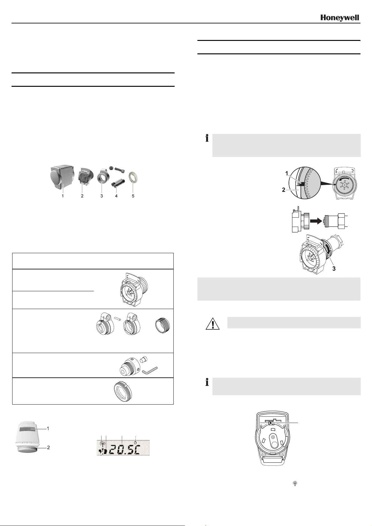
VENTILAUFSATZ MONTIEREN
Die Ventile Honeywell-Braukmann, MNG, Heimeier, Junkers,
Landis & Gyr 'Duogyr' erfordern keinen Adapter. Adapter für
Oventrop-, Danfoss-, Herz- und Vaillantventile siehe Abschnitt
“Zusätzliche Geräte oder Teile".
1. Stellrad des Ventilaufsatz
gegen den Uhrzeigersinn
drehen, bis die Nase (1)
des Stellrads am
Anschlag (2) des
Gehäuses sitzt.
2. Ventilaufsatz auf das
Heizkörperventil schieben.
3. Metallrändelmutter (3) auf
das Gewinde des Heizkörperventils schieben.
4. Metallrändelmutter ohne
Werkzeug festdrehen.
Tipp: Am einfachsten lässt sich die korrekte Montage des Ventil-
aufsatz prüfen, wenn die zentrale Heizung eingeschaltet ist.
Der Heizkörper wird bei korrekt montiertem Ventilaufsatz warm
(Stellrad am linken Anschlag).
TEACH-IN AKTIVIEREN
Der Heizkörperregler kommuniziert per Funk mit der
zentralen Bedieneinheit.
VORSICHT!
► Bei der Wahl des Betriebsorts auf ca. 1–2 m Ab-
stand zu Funkgeräten wie Funk-Kopfhörer,
schnurlose Telefone nach DECT-Standard etc.
achten.
Neue Komponenten des Einzelraum-Regelungssystems müssen
der zentralen Bedieneinheit zugeordnet werden, bevor sie in Betrieb gehen können. Dieser Vorgang wird "Teach-in" genannt.
Zuerst alle Handlungsschritte für den gesamten Teach-in durchlesen und dann ausführen. Der Teach-in-Betrieb bleibt am Heizkörperregler für maximal 4 Minuten aktiv.
► Bedienteil in unmittelbare Nähe des zugehörigen Ventilaufsatz
bringen.
1
1 Display: Zeigt aktuelle
Soll-Temperatur und
Geräteinformationen.
2 Stellrad am Bedienteil:
Ermöglicht manuelle
Temperatureinstellung.
3 Symbol für Sendeverbindung zur
zentralen Bedieneinheit.
4 Symbol für Trennung von Be-
dienteil und Ventilaufsatz.
5 Soll-Temperatur.
6 Symbol für Ist-Wert, der von der
zentralen Bedieneinheit kommt
(optional).
► Teach-in-Taste (1) ca. eine Sekunde lang drücken und dann
loslassen.
Beim Loslassen blinkt das Symbol und die Versionsnummer der Software wird 30 Sekunden lang angezeigt.
1
Page 2
Wenn in einem Raum mehrere Heizkörperregler gleichzeitig
angesteuert werden sollen:
► Teach-in-Taste der Reihe nach an allen Heizkörperreglern
drücken.
► Teach-in an der zentralen Bedieneinheit aktivieren (siehe
Bedienungsanleitung zur zentralen Bedieneinheit).
Während des Teach-ins wird das Symbol kontinuierlich im
Display des
Anzeige:
Heizkörperreglers
.
angezeigt. Es erscheint die
Der Heizkörperregler empfängt Daten von der zentralen
Bedieneinheit. Dieser Vorgang kann bis zu 4 Minuten dauern.
Misslungener Teach-in
Der Teach-in ist misslungen, wenn das Symbol erlischt.
Folgende Maßnahmen durchführen:
► Störende/abschirmende Geräte entfernen, z. B. drahtlose
Kopfhörer, schnurlose Telefone, Lautsprecher, Garagentoröffner.
► Teach-in wiederholen.
Wenn im Normalbetrieb das Symbol erlischt, ist kein erneuter
Teach-in nötig. Möglicherweise sind die Batterien der zentralen
Bedieneinheit leer. Nach einem Batteriewechsel wird der HR 80
automatisch synchronisiert.
Die Soll-Temperatur am Heizkörperregler wird automatisch auf 20 °C gesetzt.
HEIZKÖRPERREGLER FERTIG MONTIEREN
1. Haltebügel am Bedienteil
drehen, bis die Spitze
nach oben zeigt.
Die Verriegelung für den
Ventilaufsatz öffnet sich.
2. Bedienteil auf den
Ventilaufsatz schieben.
3. Haltebügel wieder zur
Seite drehen.
Bedienteil und Ventilaufsatz sind fest verbunden. Im Display
des HR 80 erlischt das Symbol
. Der Heizkörperregler ist
jetzt betriebsbereit.
Zum Abnehmen des Bedienteils in umgekehrter Reihenfolge
vorgehen.
BEDIENUNG
BATTERIEN EINSETZEN/WECHSELN
Wenn im Display Batt erscheint, müssen beide Batterien gewechselt
werden.
Sind die Batterien zu schwach, öffnet der Heizkörperregler das
Heizkörperventil vollständig.
Werden nach erfolgreichem Teach-in die Batterien gewechselt,
erscheint die Anzeige .
Der Heizkörperregler wartet auf Daten der zentralen
Bedieneinheit (siehe Abschnitt "Teach-in aktivieren").
1. Batteriefach öffnen.
2. Gegebenenfalls leere
Batterien entfernen.
3. Neue Batterien in das
Batteriefach einlegen. Auf
richtige Polung achten.
4. Batteriefach schließen.
Gebrauchte Batterien nicht mit dem Hausmüll entsorgen, sondern
entsprechend den gesetzlichen Bestimmungen zurückgeben.
Immer beide Batterien wechseln.
Nur 1,5-V-Alkaline-Batterien vom Typ LR06 verwenden.
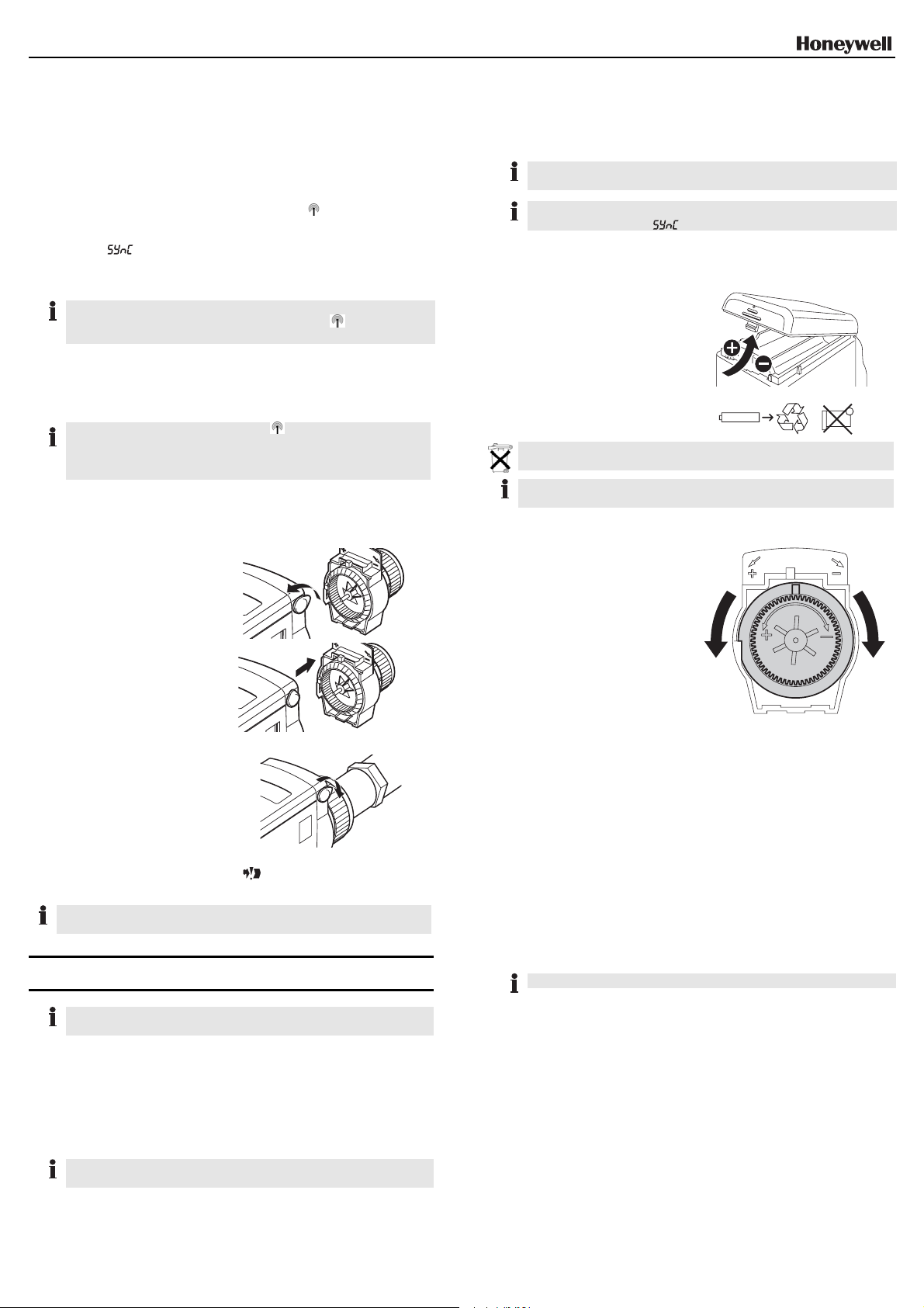
NOTBEDIENUNG BEI LEEREN BATTERIEN
1. Bedienteil vom Ventilaufsatz
trennen.
2. Heizungsventil mit dem
Stellrad am Ventilaufsatz
von Hand öffnen (in Richtung des Pluszeichens)
oder schließen (in Richtung
des Minuszeichens).
BETRIEBSARTEN DEF (STANDARDEINSTELLUNG) UND FULL
Um zwischen den beiden Betriebsarten zu wechseln, drücken
Sie die Teach-in-Taste (1, Abschnitt "Teach-in aktivieren“), bis
die jeweilige Betriebsart auf dem Display erscheint.
Betriebsart Def (Standardeinstellung)
Der HR 80 arbeitet mit dem optimalen Ventilhub, der zur Raumtemperaturregelung benötigt wird.
Betriebsart Full
Wenn der gesamte Ventilhub ausgenutzt werden soll, oder das
Ventil nicht vollständig schließt, müssen Sie den HR 80 auf die
Betriebsart full einstellen.
In der Betriebsart full verringert sich die Batterielebensdauer.
Jede lokale Änderung der Soll-Temperatur ist so lange gültig, bis
sie automatisch durch ein Zeitprogramm überschrieben wird.
Die Soll-Temperatur wird von der zentralen Bedieneinheit
geregelt und dort eingestellt. Näheres ist in der
Bedienungsanleitung der zentralen Bedieneinheit beschrieben.
SOLL-TEMPERATUR AM STELLRAD ÄNDERN
► Am Stellrad des Bedienteils drehen, bis im Display die ge-
wünschte Soll-Temperatur (zwischen 5-30 °C) angezeigt wird.
Der Bereich für die Soll-Temperatur (Standardbereich 5-30 °C)
kann an der zentralen Bedieneinheit eingeschränkt werden.
Um das Heizungsventil vollständig zu öffnen oder zu schließen:
► Am Stellrad drehen, bis im Display "OFF" (geschlossen) oder
"ON" (geöffnet) erscheint. (Wenn Temperaturlimits eingestellt
sind, wird "ON"/"OFF" nicht angezeigt.)
HR 80 AUF WERKSEINSTELLUNGEN ZURÜCKSETZEN
► Bedienteil vom Ventilaufsatz trennen, siehe Abschnitt
"Heizkörperregler fertig montieren“.
► Batterien entfernen.
► Halten Sie die Teach-in-Taste (siehe Abschnitt "Teach-in
aktivieren“) gedrückt und legen dabei die Batterien wieder ein.
► Bedienteil und Ventilaufsatz verbinden.
2
Page 3

AUTOMATISCHE FUNKTIONEN
FENSTERFUNKTION
Wenn Sie ein Fenster öffnen und dadurch die Temperatur in
kurzer Zeit stark sinkt, schließt der Heizkörperregler das
Heizungsventil, um Energie zu sparen. Im Display erscheint
dann die Meldung
.
Wenn die Temperatur wieder steigt, spätestens aber nach
30 Minuten, nimmt der Heizkörperregler wieder den normalen
Betrieb auf.
Die Fensterfunktion kann an der zentralen Bedieneinheit ausgeschaltet werden.
SCHUTZ VOR FESTSITZEN DES VENTILS
Wird das Ventil innerhalb von 2 Wochen nicht einmal vollständig
geöffnet, wird das Ventil kurzzeitig geöffnet und wieder
zugefahren. Damit wird verhindert, dass sich das Ventil
festsetzt. Im Display erscheint dann die Meldung cycle.
Der 2-Wochen Zyklus beginnt an dem Zeitpunkt, an dem das
Bedienteil mit dem Ventilaufsatz verbunden wurde.
FROSTSCHUTZ
Sinkt die Temperatur unter 5 °C, regelt der Heizkörperregler das
Heizungsventil auf 5 °C konstant.
An der zentralen Bedieneinheit kann der Frostschutzwert
(Standardwert ist 5 °C) geändert werden.
Der Frostschutz funktioniert nicht bei leeren Batterien oder
abgezogenem Bedienteil.
STATUSMELDUNG E3
Wenn das Symbol e3 auf dem Display erscheint, kann der
Motor des HR 80 nicht mehr bewegt werden.
SERVICE-MODE (NUR FÜR INSTALLATEURE)
Im Service-Mode wird der Funkkontakt zwischen Heizkörperregler, zentraler Bedieneinheit und einer Empfängereinheit
überprüft.
► Bedienteil vom Ventilaufsatz trennen (siehe Abschnitt
“Heizkörperregler fertig montieren")
► Am Stellrad drehen, bis im Display on (geöffnet) erscheint.
► Stellrad um zwei volle Umdrehungen (720°) weiterdrehen.
Im Display erscheint TesT. Der Service-Modus ist aktiviert.
Der Heizkörperregler sendet eine Testmeldung an eine evtl.
vorhandene Empfängereinheit (z. B. R6660D).
► Teach-in-Taste drücken.
Der Heizkörperregler ist empfangsbereit für eine
Testmeldung von der zentralen Bedieneinheit.
Auf dem Display geben die ersten beiden Ziffern die Anzahl
der empfangenen Testmeldungen, die rechte Ziffer die Feldstärke an (1=ausreichende Feldstärke, 5=sehr gute
Feldstärke)
Um den Service-Modus zu deaktivieren:
► Teach-in-Taste 5 sec lang drücken oder 5 Minuten warten
oder Batterien entfernen und wieder einlegen.
Service-Mode ist deaktiviert.
ENTSORGUNG (WEEE RICHTLINIE 2002/96 EG)
Entsorgen Sie Verpackung und Produkt am Ende der
Produktlebensdauer in einem entsprechenden RecyclingZentrum. Entsorgen Sie das Produkt nicht mit dem gewöhnlichen
Hausmüll. Verbrennen Sie das Produkt nicht
TECHNISCHE DATEN
Stromverbrauch (Standby)) 0.15 mW
Stromverbrauch (Motor in Betrieb 105 mW
Regelgenauigkeit 0.7 °C
Schutzklasse IP30
Umgebungstemperatur 0 °C ... +50 °C
Lagertemperatur –20 °C ... +70 °C
Luftfeuchtigkeit 5 … 95 % rel. Feuchte
Maße (L x B x H) 100 x 50 x 80 mm
Gewicht 220 g, mit Batterien
CE-Standards EN 61000-6-3
EN 61000-6-1
EN 300-220
EN 301-489
Der Heizkörperregler HR 80 ist zertifiziert nach eu.bac.
Manufactured for and on behalf of the Environmental and Combustion
Controls Division of Honeywell Technologies Sàrl,
La Pièce 16, Switzerland by its Authorized Representative:
Honeywell GmbH
Böblinger Straße 17
71101 Schönaich
http://europe.hbc.honeywell.com
Technische Änderungen vorbehalten.
Dieses Dokument ersetzt alle früheren Publikationen.
Rolle, Z.A.
MU2H0349GE51 R1209E
3
Page 4

INSTALLATION AND USER GUIDE
RADIATOR CONTROLLER HR 80
OVERVIEW AND USE
The radiator controller HR 80 is a component of the zoning
system. It can be installed on all the common radiator valves. As
the valve is a self contained unit, there is no risk of it causing
any water leakage from your heating.
The set temperature can be changed...
• manually using the adjustment dial on the operating unit of
the radiator controller
• with the command centre
PACK CONTENT
1 Operating unit
2 Coupling module
3 Adapter Danfoss RA
ADDITIONAL DEVICES OR PARTS
The following adapters/coupling modules are available for
Oventrop, Herz, Danfoss, Vaillant and Caleffi valves:
Brand Order
Oventrop HU 01
(knurled nut M30x1)
Herz HU 02
(knurled nut M28)
Danfoss Adapter Set
EVA 1-Danfoss
Vaillant Adapter
EHA 1 VAI
Caleffi –
number
073341076
073341725
072031201
072031082
OPERATING ELEMENTS AND DISPLAY
4 Batteries
5 Caleffi adapter
Adapter/coupling module
RAV
(gray)
RA (white)
(enclosed)
RAVL
(black)
enclosed
INSTALLATION
► Remove the old thermostat.
INSTALLING ADAPTER
► Select the required adapter.
► Open up the adapter and push it onto the valve as far as the
stop. Turn it while doing so until you feel it click into place.
If provided on the adapter:
► Screw the adapter firm or insert the adapter pin.
INSTALLING COUPLING MODULE
The Honeywell-Braukmann, MNG, Heimeier, Junkers,
Landis & Gyr 'Duogyr' valves do not require an adapter. For
adapters for Oventrop, Danfoss, Herz and Vaillant valves, refer to
Section "Additional devices or parts".
1. Turn the adjustment dial of
the coupling module
counterclockwise until the
nose (1) of the adjustment
dial is positioned at the
stop (2) of the housing.
2. Push coupling module onto
the radiator valve.
3. Slide metal knurled nut (3)
onto the threading of the
radiator valve.
4. Tighten the metal knurled
nut without using a tool.
Hint: The correct installation of the coupling module is best checked
with the central heating switched on. If the coupling module is
correctly installed, the radiator will become warm (adjustment
dial positioned at the left-hand stop).
ACTIVATING BINDING PROCEDURE
The radiator controller communicates with the central
operating unit via a wireless connection.
Caution!
► When selecting the operating site ensure that the
distance to wireless devices such as wireless
headphones, cordless phones etc. is approx.
1–2 m according to the DECT standard.
New components of the zoning system must be assigned to the
command centre before they can be taken into operation. This
process is called the "binding procedure".
First read through all the steps for the complete binding procedure
and then carry them out. The binding procedure mode remains
active at the radiator controller for a maximum of 4 minutes.
► Position the operating unit directly near the corresponding
coupling module.
1 Display: Shows current
set temperature and
device information.
2 Adjustment dial on the
operating unit: Allows
manual temperature
adjustment.
6 5 4 3
3 Symbol for the RF connetion to
the command centre.
4 Symbol for separating the operat-
ing unit and coupling module.
5 Set temperature
6 Symbol for actual value coming
from the command centre
(optional).
1
► Press the binding procedure button (1) for approx. one second
and then release it.
When the binding procedure button is released, the symbol
flashes and the software version number is displayed for
30 seconds.
1
Page 5

If several radiator controllers are to be controlled simultaneously
in one room:
► Press the binding procedure button on all the radiator
controllers consecutively.
► Activate binding procedure at the command centre (see
operating instructions of the command centre).
During binding procedure, the symbol is s ho wn
continuously in the display of the radiator controller. The
following is displayed:
.
The radiator controller receives data from the command
centre. This process can take up to 4 minutes.
Failed binding procedure
The binding procedure has failed if the symbol extinguishes.
Take the following measures:
► Remove the disturbing/shielding devices, e.g. wireless
headphones, cordless telephones, loudspeakers, garage door
openers.
► Repeat the binding procedure.
If the symbol extinguishes during normal operation, possible
causes are discharged batteries at the command centre. You do
not have to repeat binding operation, if the communication is
reestablished. If you remove the batteries and insert them again,
the HR80 goes direct in sync mode.
The set temperature at the radiator controller is
automatically set to 20 °C.
FINISHING INSTALLATION OF RADIATOR CONTROLLER
1. Turn the retaining bracket
on the operating unit until
the tip points upwards.
The lock on the coupling
module opens.
2. Slide the operating unit
onto the coupling module.
INSERTING/CHANGING BATTERIES
If Batt appears in the display, both batteries must be replaced.
If the batteries are too weak, the radiator controller opens the
radiator valve completely.
If the batteries are replaced after the binding procedure has been
completed, is displayed.
The radiator controller waits for data from the command
centre (see section "Activating binding procedure").
1. Open battery
compartment.
2. If necessary, remove
empty batteries.
3. Insert the new batteries
into the battery compartment. Ensure that the
polarity is correct.
4. Close the battery
compartment.
Do not dispose of batteries with household trash. They must be
returned in accordance with the local statutory requirements.
Always replace both batteries.
Only use 1.5 V alkaline batteries of the type LR06.
EMERGENCY OPERATION WITH EMPTY BATTERIES
1. Separate operating unit
from coupling module.
2. Use the adjustment dial to
open (in the direction of the
plus sign) or close (in the
direction of the minus sign)
the heating valve manually.
3. Turn the retaining bracket
to the side.
The operating unit and coupling module are connected
firmly.The
symbol disappears from the display of the
HR 80. The radiator controller is now ready for operation.
To separate operating unit and coupling module proceed in reverse
order.
OPERATION
Every local change in the setpoint temperature remains valid until
a time program overwrites it automatically.
The set temperature is controlled by the command centre and
set there as well. For further information please refer to the
operating instructions of the command centre.
CHANGING SET TEMPERATURE WITH ADJUSTMENT DIAL
► Turn the adjustment dial of the operating unit until the desired
set temperature (between 5 – 30 °C) is displayed.
The range for the set temperature (standard range: 5 – 30 °C) can
be restricted at the command centre.
In order to open or close the radiator valve completely:
► Turn the adjustment dial until "OFF" (closed) or "ON" (opened)
is displayed. (If temperature limits are set, "ON"/"OFF" is not
displayed.)
DEF (DEFAULT SETTING) AND FULL OPERATING MODES
In order to change between the two operating modes, press the
binding procedure button (1, section "Activating binding procedure") until the respective operating mode is shown on the
display.
Def (default setting) operating mode
The HR 80 operates with the optimum valve lift that is required
for room temperature control.
Full operating mode
If the complete valve lift is to be used or if the valve does not
close completely, you have to set the HR 80 to the full
operating mode.
The battery lifetime is reduced in the full operating mode.
RESETTING THE HR 80 TO THE FACTORY SETTINGS
► Separate operating unit from the valve lantern, see Section
"Finishing installation of radiator controller".
► Remove the batteries.
► Insert the batteries again while keeping the binding procedure
button (see section "Activating binding procedure") pressed.
► Attach the operating unit to the valve lantern.
2
Page 6

AUTOMATIC FUNCTIONS
WINDOW FUNCTION
If you open a window and the temperature drops sharply within a
short period, the radiator controller closes the radiator valve in
order to save energy. The display then shows the message .
When the temperature rises again, the radiator controller returns
to normal operation, however at the latest after 30 minutes.
The window function can be deactivated at the command centre.
PROTECTION AGAINST VALVE MALFUNCTION
If the valve is not opened once completely within a period of
2 weeks, the valve is opened and shut again briefly. This
ensures that the valve does not seize. The display then shows
the message cycle. The 2-week cycle begins at the moment
at which the operating unit is connected to the valve lantern.
FROST PROTECTION
If the temperature drops below 5 °C, the radiator controller
keeps the radiator valve at a constant 5 °C.
The frost-protection value (standard value: 5 °C) can be
changed at the command centre.
The frost-protection function does not function when the batteries
are empty or the operating unit is removed.
STATUS MESSAGE E3
If the symbol e3 is shown on the display, the motor of the HR 80
can no longer be moved.
SERVICE MODE (FOR INSTALLERS ONLY)
The wireless contact between the radiator controller, the
command centre and a receiver unit is checked in Service
mode.
► Separate operating unit from coupling module (see Section
"Finishing installation of radiator controller").
► Turn the adjustment dial until on (open) appears in the
display.
► Turn adjustment dial two full rotations (720°) further.
TesT is displayed. Service mode is active.
The radiator controller transmits a test message to any avail-
able receiver unit (e.g. HC60ng).
► Press the binding procedure button.
The radiator controller is ready to receive the test message
from the command centre.
The first two digits in the display indicate the number of received test messages, and the right-hand digit indicates the
field strength (1 = sufficient field strength, 5 = very good field
strength)
To deactivate Service mode:
► Press the binding procedure button for 5 seconds or wait
5 minutes or remove and then reinsert the batteries.
Service mode is deactivated.
DISPOSAL (WEEE DIRECTIVE 2002/96 EG)
At the end of the product life dispose of the packaging and
product in a corresponding recycling centre. Do not dispose of the
unit with the usual domestic refuse. Do not burn the product.
TECHNICAL DATA
Power consumption (standby) 0.15 mW
Power consumption (motor in action) 105 mW
Control accuracy 0.7 °C
Protection class IP30
Ambient temperature 0 °C ... +50 °C
Storage temperature –20 °C ... +70 °C
Humidity 5 … 95 % rel. humidity
Dimensions (L x W x H) 100 x 50 x 80 mm
Weight 220 g, with batteries
CE standards EN 61000-6-3
EN 61000-6-1
EN 300-220
EN 301-489
The radiator controller HR 80 is certified according to eu.bac.
Manufactured for and on behalf of the Environmental and Combustion
Controls Division of Honeywell Technologies Sàrl,
La Pièce 16, Switzerland by its Authorized Representative:
Honeywell GmbH
Böblinger Straße 17
71101 Schönaich
http://europe.hbc.honeywell.com
The right is reserved to make modifications.
This document replaces all previous publications.
Rolle, Z.A.
MU2H0349GE51 R1209E
3
 Loading...