

Honeywell HEMS II User Manual

McDonald’s HEMS II
Wayport Interface Manual

INTRODUCTION
The purpose of this document is to provide general guidelines, for Owner/Operators that have installed
the McDonald’s AT&T Wayport Connectivity Solution in their restaurants. Wayportwill enable them to
connect theHoneywell EnergyManagement System to the Internet.
FUNCTION OF OWNER/OPERATOR PORT
The Owner/Operator port(red)was provided in responseto thoseOwner/Operatorswho needed the ability
to connect devices in the restaurant, other than McDonald’s applications, to the Wayport solution, and
leverage the access to the Internet; the Wayport Owner/Operator port is used to provide this service.
It contains a single IP address on each side of the Wayport solution for your direct use. This means that you
can attach only one computer, router or network appliance device directly to the Wayport solution.
It is important to note that this IP address appears different, depending on whether you are on the inside
or outside of the restaurant (see below). On the inside, an internal IP address, and associated
information, is used to actually configure the device, and will be used once. This is a private address,
and it is masked by the Wayport hardware in order to be protected from attack or compromise. The
external IP address is a translated “virtual” IP address, which is used to reach your hardware from the
outside (Internet).
CONNECTION
The Wayport solutioncontainsmultiplehardware devices housed in a single cabinet. It will typically only be
installed in one of a few locations within the restaurant, with the most probable location being in the
manager’s office area.
1. Locate the Wayport connectivity enclosure.
2. There are four ports on the bottom of the enclosure, which are labeled according to the below
diagram. Only the first port (red jack) is usable by the Owner/Operator for connection of your
equipment. The remaining ports are either actively used for cashless, or designated for McDonald’s
specific applications.YourEnergy Management System or computerwillnotworkproperly if you connect
to the wrong port.
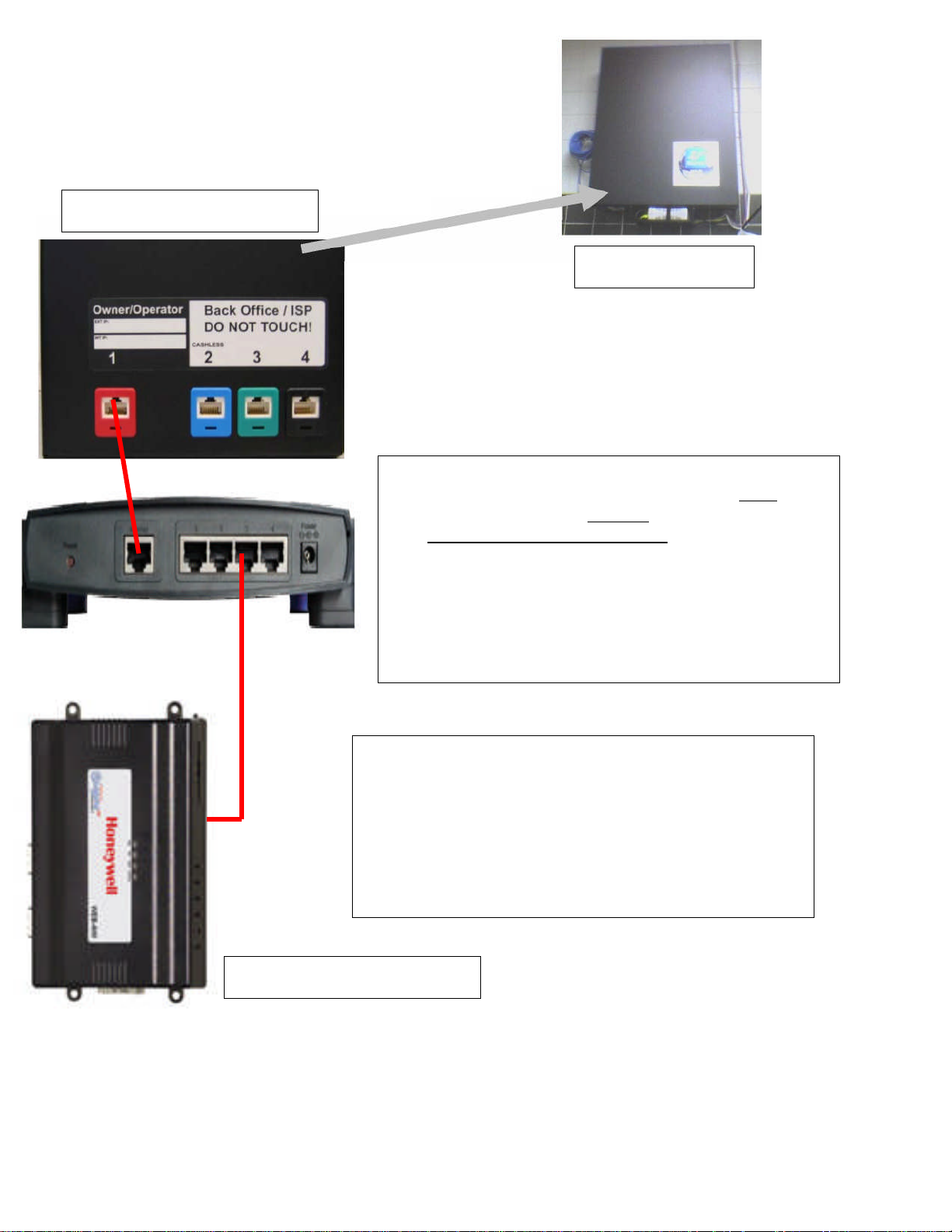
Typical Wayport Unit
Typical Wayport Connections
Linksys BEFSR41 Cable/DSL Router with/4
-
port switch or equal.
Furnished by owner/operator or others. This item is not
WE
Bs Unit inside HEMS II Panel
Configure WEBs unit
furnished by Honeywell and does not come with the Wayport
Unit. The installer must purchase locally. Configure router
from Basic Setup as incoming “Obtain an IP Automatically”.
Change “Local IP Address” to the following: 192.168.100.1 and
leave Subnet Mask at the following: 255.255.255.0. Or change
to 255.255.255.252. Configure router to port forward ports 80,
1911 and 3011. Refer to attached router manual for
adjustments and settings.
Change Port #1 as follows:
IP Address = 192.168.100.10
Subnet Mask = 255.255.255.0
Or 255.255.255.252
Gateway = 192.168.100.1
Port #2 configured to communicate with Touch Screen PC on
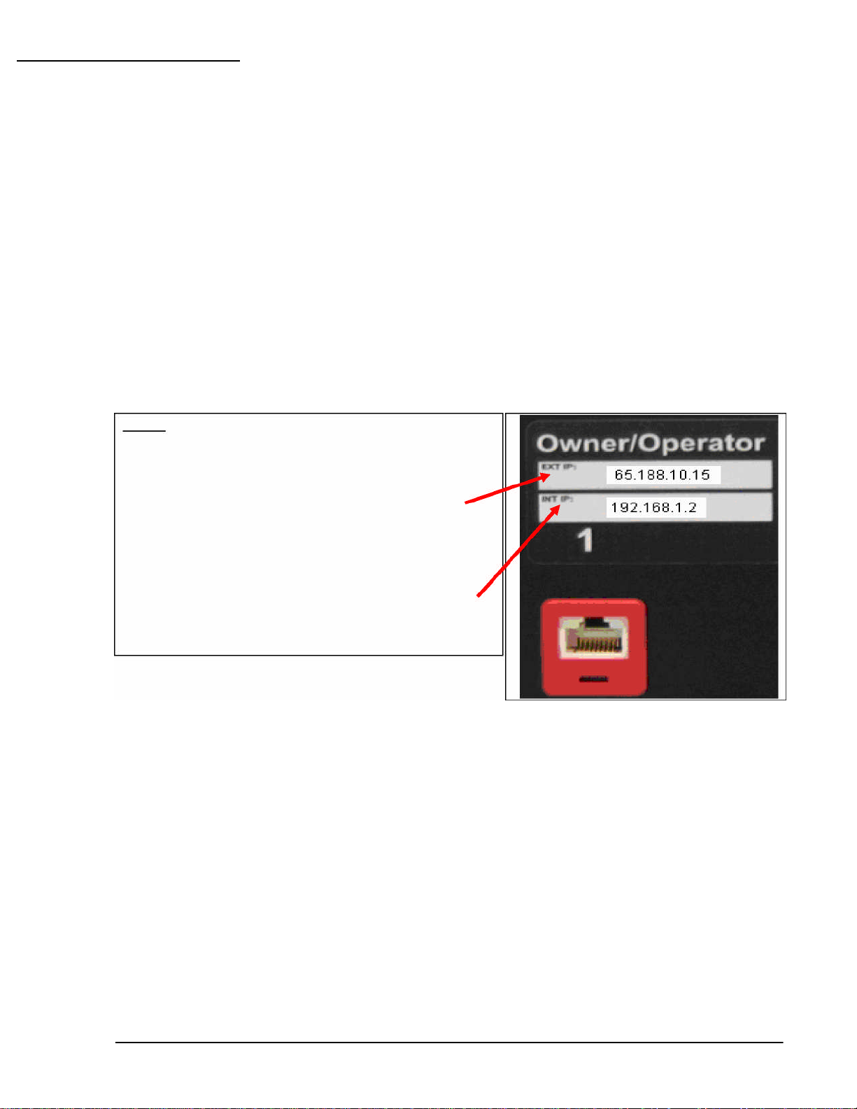
SETUP AND OPERATION
The external IP address (here labeled as
the restaurant.
The internal IP address is used by the device
NOTE:
The internal and external IP addressing
It is not possible for Honeywell to predict or directly support all of the potential types of computers, DVR’s,
CCTV or other hardware devices which may be attached to the Wayport Owner/Operator port. Please refer
to the specific manufacturer’s operations and user guides, for the computer or appliance that you would like to
connect to the Wayport hardware, for specific information on configuration and setup when linking to Internet
facing services.
As described briefly above in the functional area, there is an internal addressing mechanism and an
external addressing mechanism, when using the Owner/Operator port. When you want to remotely
connect to the HEMS II system; you will use the external IP address in order to connect to the system
from your home or office.
information that you need should be labeled on
the Wayport solution in the restaurant.
65.188.10.15) is used outside the store, by
the Owner/Operator, to reach the device in
inside the store to configure to the local
network. This information is masked from the
outside, for security reaso ns. In a ll cases,
the device should b e configured for an IP
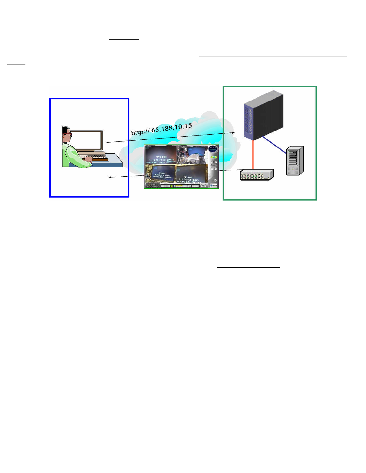
REMOTELY CONNECTING TO YOUR HEMS II System
If you want to remotely connect to your HEMS II System in the restaurant, you will need to use the external IP
address for accessing it. In the example above, you would type 65.188.10.15 into the web browser on your
computer in your office or home. Your PC will connect across the Internet to the HEMS II System in the
restaurant using only this address. This is an example only. Use the individual IP address assigned to your
store.
Owner/Operator Office Internet Restaurant
SUPPORT
Honeywell cannot directly support any of the attached devices an Owner/Operator may choose to
connect to this red port. Honeywell’s support services are specifically limited to providing assistance
to the owner/operator in ensuring that the HEMS II panel is enabled and functioning properly,as well
as ensuring the correct information was used to configure the device. Neither McDonald’s, Honeywell
nor Wayport can provide support for your device itself. You must rely on your manufacturer’s service
plan, an internal Operator IT staff,or a contracted service you obtain to provide the necessary support for
your needs.
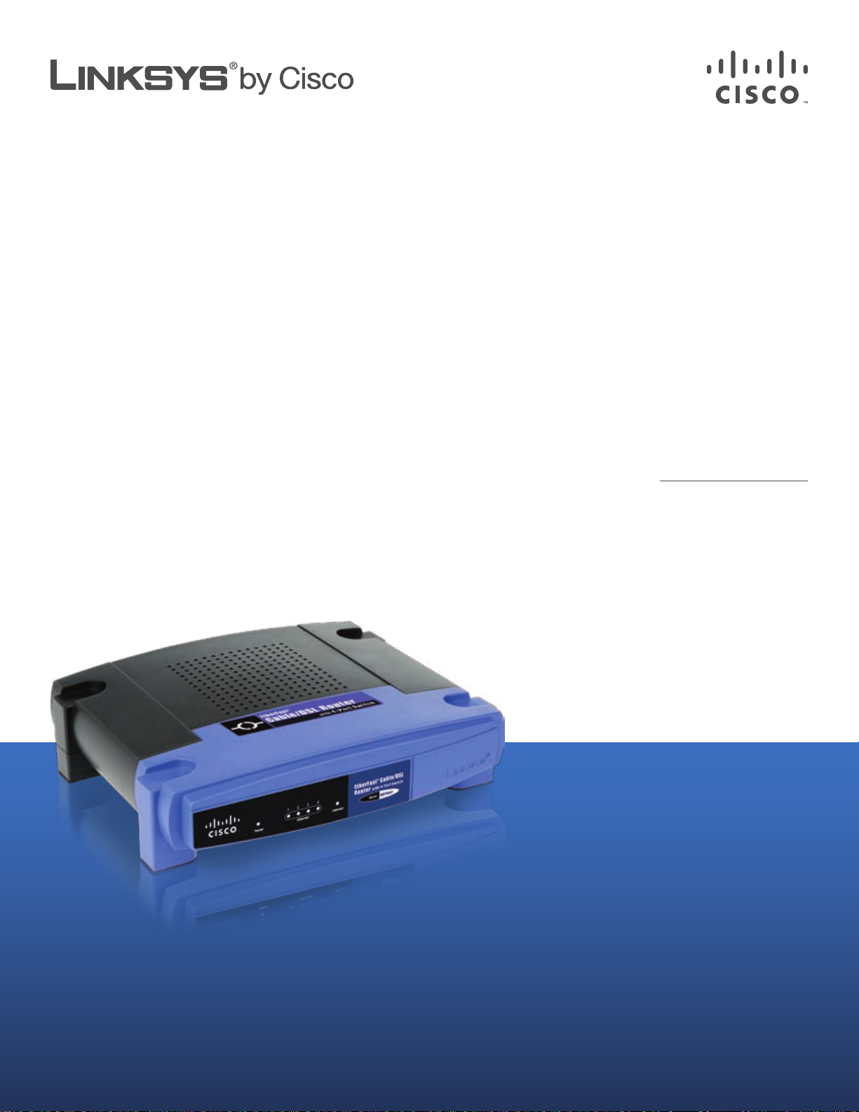
USER GUIDE
EtherFast® Cable/DSL Router
with 4-Port Switch
Model: BEFSR41

Table of Contents
Chapter 1: Product Overview 2
Front Panel. . . . . . . . . . . . . . . . . . . . . . . . . . . . . . . . . . . . . . . . . . . . . . . . . . 2
Back Panel . . . . . . . . . . . . . . . . . . . . . . . . . . . . . . . . . . . . . . . . . . . . . . . . . . 2
Chapter 2: Advanced Conguration 3
Setup > Basic Setup . . . . . . . . . . . . . . . . . . . . . . . . . . . . . . . . . . . . . . . . . . . . 3
Setup > DDNS. . . . . . . . . . . . . . . . . . . . . . . . . . . . . . . . . . . . . . . . . . . . . . . . 7
Setup > MAC Address Clone. . . . . . . . . . . . . . . . . . . . . . . . . . . . . . . . . . . . . . . 7
Setup > Advanced Routing . . . . . . . . . . . . . . . . . . . . . . . . . . . . . . . . . . . . . . . 8
Security > Filter. . . . . . . . . . . . . . . . . . . . . . . . . . . . . . . . . . . . . . . . . . . . . . . 9
Security > VPN Passthrough. . . . . . . . . . . . . . . . . . . . . . . . . . . . . . . . . . . . . . .10
Applications and Gaming > Port Range Forwarding . . . . . . . . . . . . . . . . . . . . . . .10
Applications & Gaming > Port Triggering . . . . . . . . . . . . . . . . . . . . . . . . . . . . . .10
Applications and Gaming > UPnP Forwarding . . . . . . . . . . . . . . . . . . . . . . . . . . .11
Applications and Gaming > DMZ . . . . . . . . . . . . . . . . . . . . . . . . . . . . . . . . . . .12
Applications and Gaming > QoS . . . . . . . . . . . . . . . . . . . . . . . . . . . . . . . . . . . .12
Administration > Management. . . . . . . . . . . . . . . . . . . . . . . . . . . . . . . . . . . . .13
Administration > Log . . . . . . . . . . . . . . . . . . . . . . . . . . . . . . . . . . . . . . . . . . .14
Administration > Factory Defaults . . . . . . . . . . . . . . . . . . . . . . . . . . . . . . . . . . .15
Administration > Firmware Upgrade . . . . . . . . . . . . . . . . . . . . . . . . . . . . . . . . .15
Status > Router . . . . . . . . . . . . . . . . . . . . . . . . . . . . . . . . . . . . . . . . . . . . . . .16
Status > Local Network . . . . . . . . . . . . . . . . . . . . . . . . . . . . . . . . . . . . . . . . . .16
Appendix A: Troubleshooting 17
Appendix B: Specications 18
Appendix C: Warranty Information 19
Limited Warranty. . . . . . . . . . . . . . . . . . . . . . . . . . . . . . . . . . . . . . . . . . . . . .19
Appendix D: Regulatory Information 21
FCC Statement . . . . . . . . . . . . . . . . . . . . . . . . . . . . . . . . . . . . . . . . . . . . . . .21
Safety Notices. . . . . . . . . . . . . . . . . . . . . . . . . . . . . . . . . . . . . . . . . . . . . . . .21
Industry Canada Statement . . . . . . . . . . . . . . . . . . . . . . . . . . . . . . . . . . . . . . .21
User Information for Consumer Products Covered by EU Directive 2002/96/EC on Waste
Electric and Electronic Equipment (WEEE) . . . . . . . . . . . . . . . . . . . . . . . . . . . . . .22
Appendix E: Software License Agreement 26
Software in Linksys Products . . . . . . . . . . . . . . . . . . . . . . . . . . . . . . . . . . . . . .26
Software Licenses . . . . . . . . . . . . . . . . . . . . . . . . . . . . . . . . . . . . . . . . . . . . .26
EtherFast Cable/DSL Router with 4-Port Switch
i
About This Guide
Icon Descriptions
While reading through the User Guide you may see
various icons that call attention to specific items. Below is
a description of these icons:
NOTE: This check mark indicates that there is
a note of interest and is something that you
should pay special attention to while using the
product.
WARNING: This exclamation point indicates
that there is a caution or warning and it is
something that could damage your property or
product.
About This Guide
WEB: This globe icon indicates a noteworthy
website address or e-mail address.
Online Resources
Website addresses in this document are listed without
http:// in front of the address because most current web
browsers do not require it. If you use an older web browser,
you may have to add http:// in front of the web address.
Resource Website
Linksys www.linksys.com
Linksys International www.linksys.com/international
Glossary www.linksys.com/glossary
Network Security www.linksys.com/security
Copyright and Trademarks
Linksys, EtherFast, Cisco, and the Cisco Logo
are registered trademarks or trademarks
of Cisco Systems, Inc. and/or its affiliates
in the U.S. and certain other countries.
Copyright © 2008 Cisco Systems, Inc. All
rights reserved. Other brands and product
names are trademarks or registered
trademarks of their respective holders.
EtherFast Cable/DSL Router with 4-Port Switch
1
Chapter 1
Product Overview
Chapter 1: Product Overview
Thank you for choosing the Linksys by Cisco EtherFast
Cable/DSL Router with 4-Port Switch. The Router lets
you access the Internet through its four switched ports.
You can also use the Router to share resources such as
computers, printers and files. A variety of security features
help to protect your data and your privacy while online.
Security features include a Stateful Packet Inspection (SPI)
firewall and NAT technology. Configuring the Router is
easy using the provided browser-based utility.
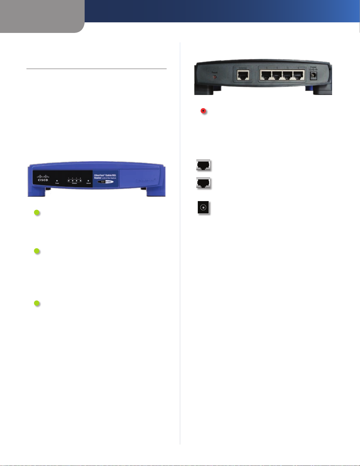
Front Panel
Power (Green) The Power LED lights up and
will stay on while the Router is powered on.
It flashes when the Router goes through its
self-diagnostic mode during every boot-up or
upgrades its firmware.
Back Panel
Reset There are two ways to reset the Router to
its factory default settings. Use a straightened
paper clip or similar object to press and hold the
Reset button for approximately five seconds.
You can also restore the defaults from the
Administration > Factory Defaults screen of the
Router’s web-based utility.
Internet The Internet port is where you will
connect your cable or DSL Internet connection.
1, 2, 3, 4 These Ethernet ports (1, 2, 3, 4)
connect the Router to computers on your wired
network and other Ethernet network devices.
Power The Power port is where you will
connect the power adapter.
1, 2, 3, 4 (Green) These numbered LEDs,
corresponding with the numbered ports on the
Router’s back panel, serve two purposes. If the
LED is continuously lit, the Router is successfully
connected to a device through that port. A
flashing LED indicates network activity over
that port.
Internet (Green) The Internet LED lights up
when there is a connection made through the
Internet port. A flashing LED indicates network
activity over the Internet port.
EtherFast Cable/DSL Router with 4-Port Switch
2
Chapter 2
Chapter 2: Advanced Configuration
After setting up the Router with the Setup Wizard (located
on the CD-ROM), the Router will be ready for use. However,
if you’d like to change its advanced settings, use the
Router’s web-based utility. This chapter describes each
web page of the utility and each page’s key functions. You
can access the utility via a web browser on a computer
connected to the Router.
The web-based utility has these main tabs: Setup, Security,
Applications & Gaming, Administration, and Status.
Additional tabs will be available after you click one of the
main tabs.
NOTE: When first installing the Router, you
should use the Setup Wizard on the Setup
CD-ROM. If you want to configure advanced
settings, use this chapter to learn about the
web-based utility.
How to Access the Web-Based Utility
Advanced Configuration
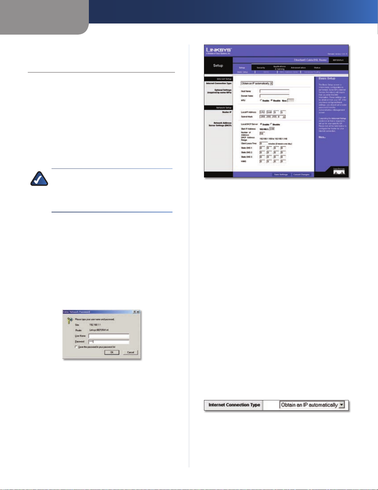
Setup > Basic Setup
Internet Setup
The Internet Setup section configures the Router to your
Internet connection. Most of this information can be
obtained through your Internet Service Provider (ISP).
To access the web-based utility, launch the web browser on
your computer, and enter the Router’s default IP address,
192.168.1.1, in the Address field. Then, press Enter.
A login screen will appear. Leave the User Name field
blank. The first time you open the web-based utility, use
the default password admin. (You can set a new password
from the Administration > Management screen.) Click OK
to continue.
Login Screen
Setup > Basic Setup
The first screen that appears is the Basic Setup screen. This
allows you to change the Router’s general settings.
Internet Connection Type
Select the type of Internet connection your ISP provides
from the drop-down menu. These are the available types:
Obtain an IP Automatically •
Static IP •
PPPoE •
RAS •
PPTP •
Heart Beat Signal •
L2TP •
Obtain an IP Automatically
By default, the Router’s Internet Connection Type is set to
Obtain an IP automatically, which should be kept only if
your ISP supports DHCP or you are connecting through a
dynamic IP address. (This option usually applies to cable
connections.)
Internet Connection Type > Obtain an IP Automatically
EtherFast Cable/DSL Router with 4-Port Switch
3
Chapter 2
Advanced Configuration
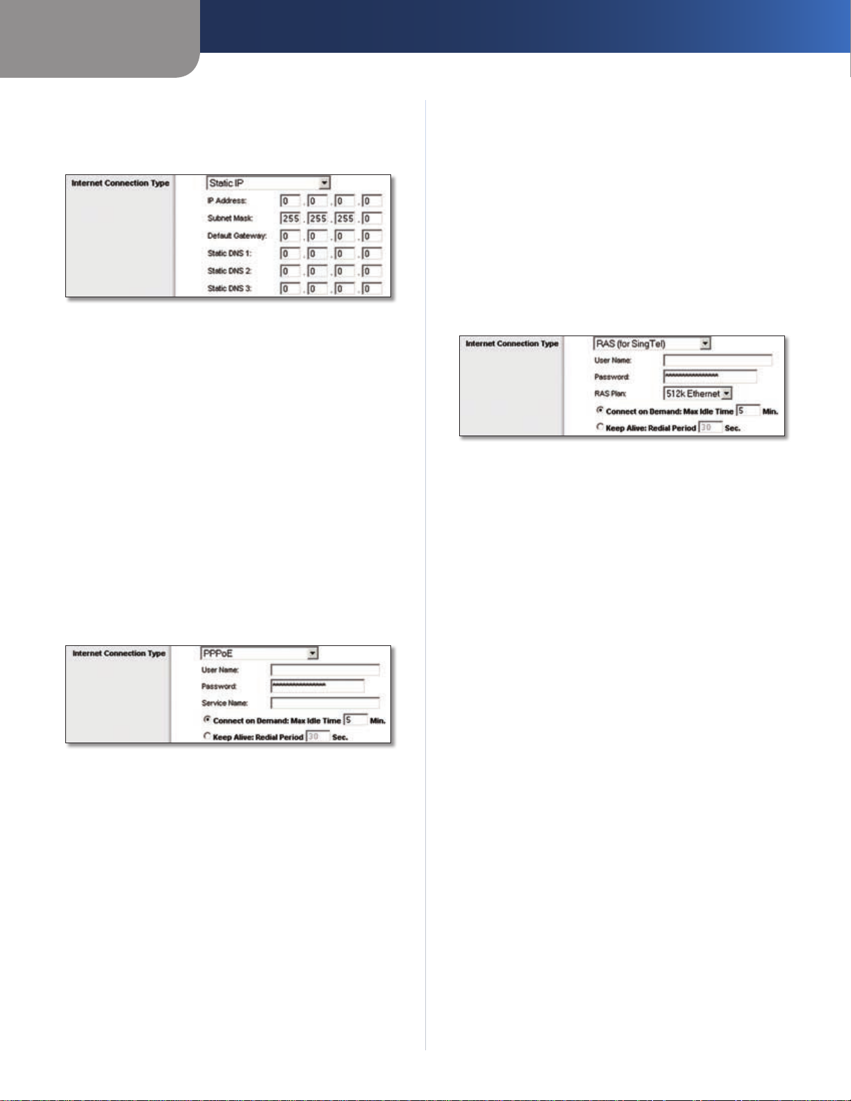
Static IP
If you are required to use a permanent IP address to
connect to the Internet, select Static IP.
Internet Connection Type > Static IP
IP Address Enter the Router’s IP address, as seen from the
Internet. This is provided by your ISP.
Subnet Mask Enter the Router’s subnet mask, as seen by
users on the Internet (including your ISP). This is provided
by your ISP.
Default Gateway Your ISP will provide you with the IP
address of the ISP server.
Static DNS 1-3 Your ISP will provide you with at least one
DNS (Domain Name System) server IP address.
PPPoE
Some DSL-based ISPs use PPPoE (Point-to-Point Protocol
over Ethernet) to establish Internet connections. If you are
connected to the Internet through a DSL line, check with
your ISP to see if they use PPPoE. If they do, you will have
to enable PPPoE.
Keep Alive: Redial Period If you select this option,
the Router will periodically check your Internet
connection. If you are disconnected, then the Router
will automatically re-establish your connection. To use
this option, select Keep Alive. In the Redial Period field,
you specify how often you want the Router to check
the Internet connection. The default Redial Period is
30 seconds.
RAS
Remote Access Service (RAS) is a service that applies to
connections in Singapore only. For users in Singapore,
check with Singtel for information on RAS.
Internet Connection Type > RAS
User Name and Password Enter the User Name and
Password provided by Singtel.
RAS Plan Select the type of plan you have.
Connect on Demand: Max Idle Time You can configure
the Router to cut the Internet connection after it has been
inactive for a specified period of time (Max Idle Time). If
your Internet connection has been terminated due to
inactivity, Connect on Demand enables the Router to
automatically re-establish your connection as soon as you
attempt to access the Internet again. To use this option,
select Connect on Demand. In the Max Idle Time field,
enter the number of minutes you want to have elapsed
before your Internet connection terminates. The default
Max Idle Time is 5 minutes.
Internet Connection Type > PPPoE
User Name and Password Enter the User Name and
Password provided by your ISP.
Service Name If provided by your ISP, enter the Service
Name.
Connect on Demand: Max Idle Time You can configure
the Router to cut the Internet connection after it has been
inactive for a specified period of time (Max Idle Time). If
your Internet connection has been terminated due to
inactivity, Connect on Demand enables the Router to
automatically re-establish your connection as soon as you
attempt to access the Internet again. To use this option,
select Connect on Demand. In the Max Idle Time field,
enter the number of minutes you want to have elapsed
before your Internet connection terminates. The default
Max Idle Time is 5 minutes.
EtherFast Cable/DSL Router with 4-Port Switch
Keep Alive: Redial Period
Router will periodically check your Internet connection. If
you are disconnected, then the Router will automatically
re-establish your connection. To use this option, select
Keep Alive. In the Redial Period field, you specify how often
you want the Router to check the Internet connection. The
default value is 30 seconds.
If you select this option, the
4
Chapter 2
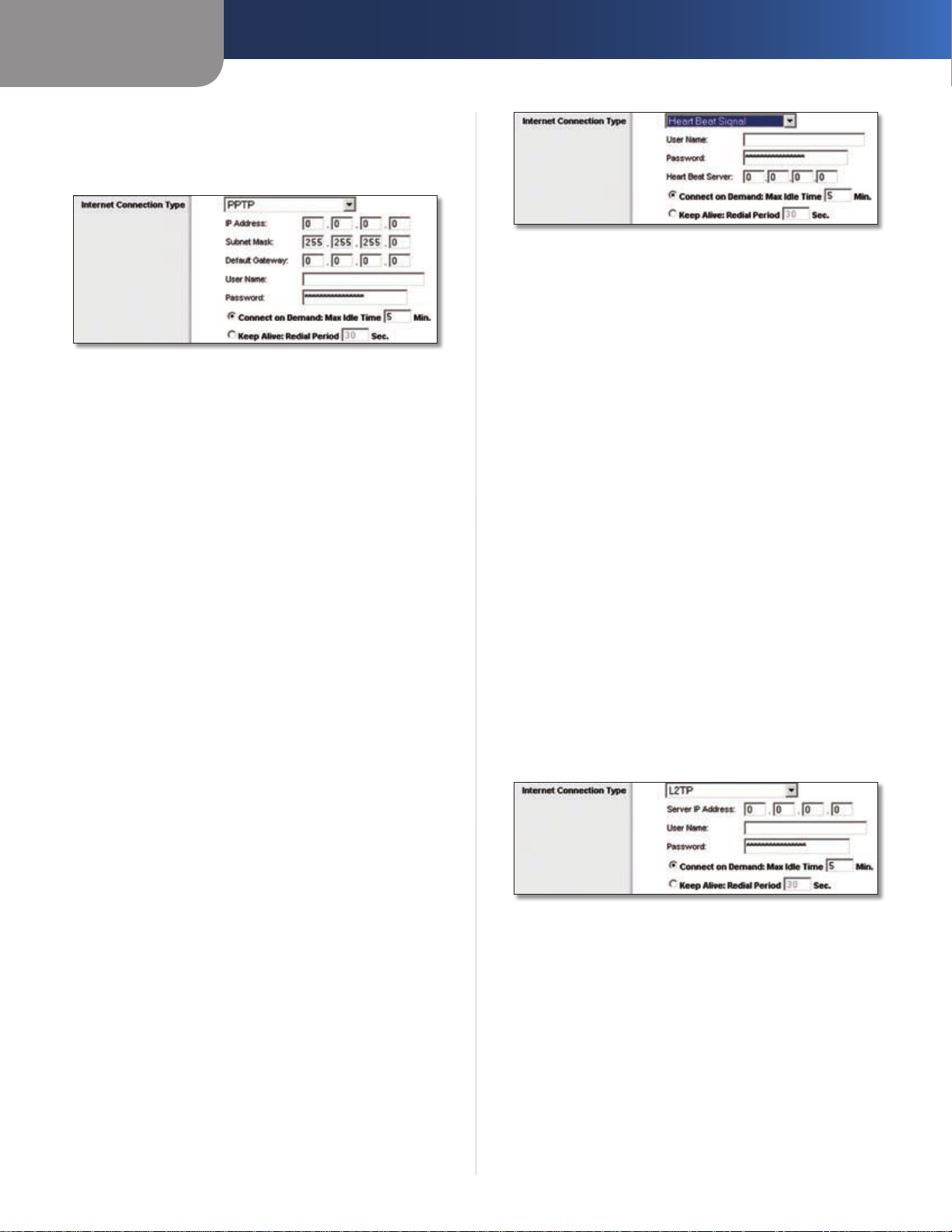
PPTP
Point-to-Point Tunneling Protocol (PPTP) is a service that
applies to connections in Europe only.
Internet Connection Type > PPTP
IP Address Enter the Router’s IP address, as seen from the
Internet. This is provided by your ISP.
Subnet Mask Enter the Router’s subnet mask, as seen by
users on the Internet (including your ISP). This is provided
by your ISP.
Default Gateway Your ISP will provide you with the IP
address of the ISP server.
User Name and Password Enter the User Name and
Password provided by your ISP.
Connect on Demand: Max Idle Time You can configure
the Router to cut the Internet connection after it has been
inactive for a specified period of time (Max Idle Time). If
your Internet connection has been terminated due to
inactivity, Connect on Demand enables the Router to
automatically re-establish your connection as soon as you
attempt to access the Internet again. To use this option,
select Connect on Demand. In the Max Idle Time field,
enter the number of minutes you want to have elapsed
before your Internet connection terminates. The default
Max Idle Time is 5 minutes.
Advanced Configuration
Internet Connection Type > Heart Beat Signal
User Name and Password Enter the User Name and
Password provided by your ISP.
Heart Beat Server Enter the IP address of your ISP’s Heart
Beat server. This is provided by your ISP.
Connect on Demand: Max Idle Time You can configure
the Router to cut the Internet connection after it has been
inactive for a specified period of time (Max Idle Time). If
your Internet connection has been terminated due to
inactivity, Connect on Demand enables the Router to
automatically re-establish your connection as soon as you
attempt to access the Internet again. To use this option,
select Connect on Demand. In the Max Idle Time field,
enter the number of minutes you want to have elapsed
before your Internet connection terminates. The default
Max Idle Time is 5 minutes.
Keep Alive: Redial Period
Router will periodically check your Internet connection. If
you are disconnected, then the Router will automatically
re-establish your connection. To use this option, select
Keep Alive. In the Redial Period field, you specify how often
you want the Router to check the Internet connection. The
default value is 30 seconds.
L2TP
L2TP is a service that applies to connections in Israel only.
If you select this option, the
Keep Alive: Redial Period
Router will periodically check your Internet connection. If
you are disconnected, then the Router will automatically
re-establish your connection. To use this option, select
Keep Alive. In the Redial Period field, you specify how often
you want the Router to check the Internet connection. The
default value is 30 seconds.
If you select this option, the
Heart Beat Signal
Heart Beat Signal is a service used in Australia only. If you
are using a Heart Beat Signal connection, check with your
ISP for the necessary setup information.
EtherFast Cable/DSL Router with 4-Port Switch
Internet Connection Type > L2TP
Server IP Address Enter the IP address of the L2TP server.
This is provided by your ISP.
User Name and Password Enter the User Name and
Password provided by your ISP.
Connect on Demand: Max Idle Time You can configure
the Router to cut the Internet connection after it has been
inactive for a specified period of time (Max Idle Time). If
your Internet connection has been terminated due to
inactivity, Connect on Demand enables the Router to
automatically re-establish your connection as soon as you
attempt to access the Internet again. To use this option,
select Connect on Demand. In the Max Idle Time field,
5
Chapter 2
Advanced Configuration
enter the number of minutes you want to have elapsed
before your Internet connection terminates. The default
Max Idle Time is 5 minutes.
Keep Alive: Redial Period If you select this option,
the Router will periodically check your Internet
connection. If you are disconnected, then the Router
will automatically re-establish your connection. To use
this option, select Keep Alive. In the Redial Period field,
you specify how often you want the Router to check
the Internet connection. The default Redial Period is
30 seconds.
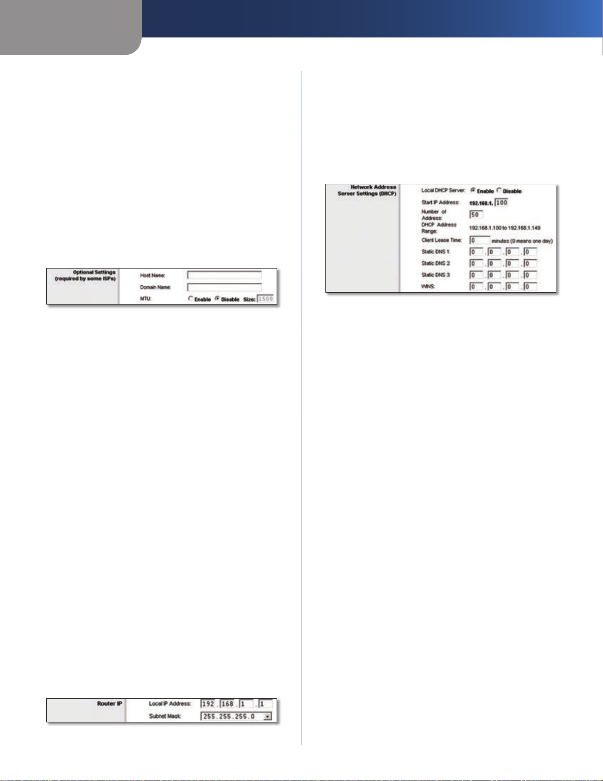
Optional Settings
Some of these settings may be required by your ISP. Verify
with your ISP before making any changes.
Optional Settings
Host Name and Domain Name These fields allow you to
supply a host and domain name for the Router. Some ISPs,
usually cable ISPs, require these names as identification.
You may have to check with your ISP to see if your
broadband Internet service has been configured with a
host and domain name. In most cases, leaving these fields
blank will work.
MTU MTU is the Maximum Transmission Unit. It specifies
the largest packet size permitted for Internet transmission.
Select Enable if you want to manually enter the largest
packet size that is transmitted. To have the Router select
the best MTU for your Internet connection, keep the
default setting, Disable.
Size When Manual is selected in the MTU field, this option
is enabled. Leave this value in the 1200 to 1500 range. The
default size depends on the Internet Connection Type:
DHCP, Static IP, or Telstra: • 1500
PPPoE: • 1492
PPTP or L2TP: • 1460
Network Setup
The Network Setup section changes the settings on the
network connected to the Router’s Ethernet ports.
Router IP
This presents both the Router’s IP Address and Subnet
Mask as seen by your network.
Network Address Server Settings (DHCP)
The settings allow you to configure the Router’s Dynamic
Host Configuration Protocol (DHCP) server function. The
Router can be used as a DHCP server for your network. A
DHCP server automatically assigns an IP address to each
computer on your network. If you choose to enable the
Router’s DHCP server option, make sure there is no other
DHCP server on your network.
Network Address Server Settings (DHCP)
Local DHCP Server DHCP is enabled by factory default.
If you already have a DHCP server on your network, or you
don’t want a DHCP server, then select Disable (no other
DHCP features will be available).
Start IP Address Enter a value for the DHCP server to
start with when is
default IP address is 192.168.1.1, the Start IP Address must
be 192.168.1.2 or greater, but smaller than 192.168.1.253.
The default is 192.168.1.100
Number of Address Enter the maximum number of
computers that you want the DHCP server to assign IP
addresses to. This number cannot be greater than 253.
The default is 50.
DHCP Address Range Displayed here is the range of
available IP addresses.
Client Lease Time The Client Lease Time is the amount
of time a network user will be allowed connection to the
Router with their current dynamic IP address. Enter the
amount of time, in minutes, that the user will be “leased”
this dynamic IP address. After the time is up, the user will
be automatically assigned a new dynamic IP address. The
default is 0 minutes, which means one day.
Static DNS 1-3
the Internet translates domain or website names into
Internet addresses or URLs. Your ISP will provide you with at
least one DNS Server IP address. If you wish to use another,
enter that IP address in one of these fields. You can enter up
to three DNS Server IP addresses here. The Router will use
these for quicker access to functioning DNS servers
suing IP addresses. Because the Router’s
.
The Domain Name System (DNS) is how
.
Router IP
EtherFast Cable/DSL Router with 4-Port Switch
WINS The Windows Internet Naming Service (WINS)
manages each PC’s interaction with the Internet. If you
use a WINS server, enter that server’s IP address here.
Otherwise, leave this blank.
6
Chapter 2
Advanced Configuration
Click Save Settings to apply your changes, or click Cancel
Changes to cancel your changes.
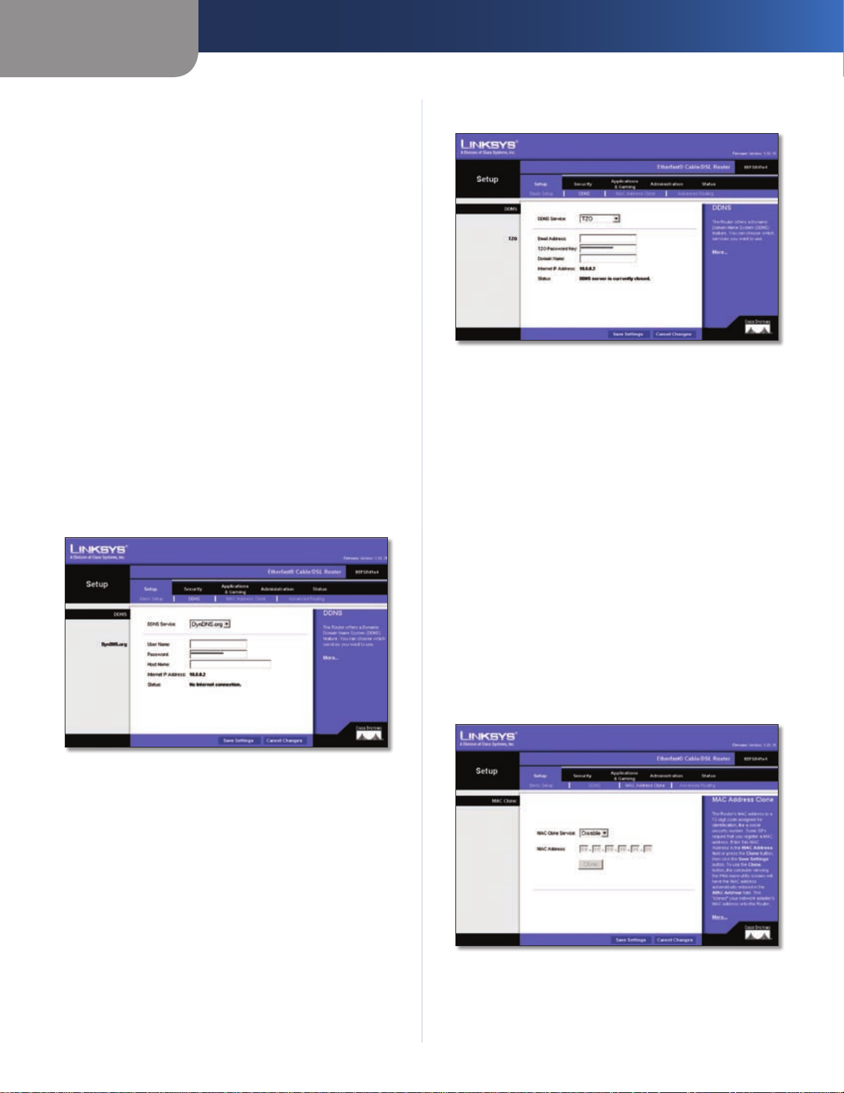
Setup > DDNS
The Router offers a Dynamic Domain Name System (DDNS)
feature. DDNS lets you assign a fixed host and domain
name to a dynamic Internet IP address. It is useful when
you are hosting your own website, FTP server, or other
server behind the Router.
Before you can use this feature, you need to sign
up for DDNS service with a DDNS service provider,
www.dyndns.org or www.TZO.com. If you do not want to
use this feature, keep the default setting, Disabled.
DDNS
DDNS Service
If your DDNS service is provided by DynDNS.org, then
select DynDNS.org from the drop-down menu. If your
DDNS service is provided by TZO, then select TZO. The
features available on the DDNS screen will vary, depending
on which DDNS service provider you use.
DynDNS.org
TZO.com
Setup > DDNS > TZO
E-mail Address, TZO Password Key, and Domain
Name Enter the settings of the account you set up with
TZO.
Internet IP Address The Router’s Internet IP address is
displayed here. Because it is dynamic, it will change.
Status The status of the DDNS service connection is
displayed here.
Click Save Settings to apply your changes, or click Cancel
Changes to cancel your changes.
Setup > DDNS > DynDNS.org
User Name Enter the User Name for your DDNS account.
Password Enter the Password for your DDNS account.
Host Name The is the DDNS URL assigned by the DDNS
service.
Internet IP Address The Router’s Internet IP address is
displayed here. Because it is dynamic, it will change.
Status The status of the DDNS service connection is
displayed here.
Click Save Settings to apply your changes, or click Cancel
Changes to cancel your changes.
Setup > MAC Address Clone
A MAC address is a 12-digit code assigned to a unique
piece of hardware for identification. Some ISPs will require
you to register a MAC address in order to access the
Internet. If you do not wish to re-register the MAC address
with your ISP, you may assign the MAC address you have
currently registered with your ISP to the Router with the
MAC Address Clone feature.
Setup > MAC Address Clone
EtherFast Cable/DSL Router with 4-Port Switch
7
 Loading...