

Honeywell HEMS II Owner's Manual
McDonald’s HEMS II
End User Operations Manual

Table of Contents
Overview………………………………………………………………………...3
Navigation to Login Page from local or remote personal computer.…..……4
Local Personal Computer & Remote Personal Computer Login …………..5
Panel Face Mounted Display Local Login…..………………………………..6
Home Page……………………………………………………………………....7-12
HVAC Units…………………………………………………………………….13
Schedules & Holidays………………………………………………………….14-17
Data Logging and Trended Points…………………………………………….18
Electrical Demand Limiting Adjustments…………………………………….19
Lighting Photocell Adjustments………………………………………………..19
Embedded Touch Screen “Operating Instructions” Link…………………....20-27
HEMS II System Drawings & Sequence of Operations……………………....28-37
McDonald’s HEMS II page 2

Overview
McDonald’s HEMS II Energy Management Control System & User Interface
The McDonald’s HEMS II energy management and control system runs on a WEB -201™ (Java Application
Control Engine). The WEB -201 is a compact, embedded controller/server platform. It combines integrated
control, supervision, data logging, alarming, scheduling and network management functions with Internet
connectivity and web serving capabilities in a small, compact platform. The WEB -201 makes it possible to
control and manage external devices over your local network or the Internet and present real-time information
to users in web-based graphical views.
The HEMS II system is complete in a 36” X 24” X 4” stainless steel panel with a local touch screen operator
interface display. All system set points and changes can be made from this local display. With internet access
provided to the HEMS II, all information and set points are available remotely from any PC browser interface.
The system is designed to monitor and/or control the following items:
(3) Roof Top Mounted HVAC Units.
Freezer/Cooler Temperatures and associated Door Opened/Closed status.
Outdoor air temperature.
HVAC Unit Space Temperatures, Discharge Air (supply) Temperatures and Room Temperature Set
Points.
Electrical Demand and Electrical Consumption.
Parking Lot Lights, Exterior Signage Lights, Customer (Dining Area) Lights.
Employee/Kitchen Lights and Play Place Lights (if present).
Outdoor Light Level from a Photocell.
Your installed system may have additional points of control or monitoring that are not covered or included in
this document.
Additional points could be:
Drive through heater control.
Kitchen equipment monitoring.
Interface to your security system for status.
Water heater control.
Additional Roof Top Mounted HVAC/Units.
Bulk CO2 levels near beverage and CO2 storage tanks.
Or additional monitoring & control points that have been customized for your facility.
McDonald’s HEMS II page 3

Navigation to Login Page from Local or Remote Personal Computer location
Open internet
browser and enter
store IP address here:
To begin: First open your internet browser and enter the WEBs Unit IP address in
the "address bar". The WEBs Unit IP address will be furnished to you by the
installer of the system. Additionally, you may consider installing a short cut icon on
your personal computer Desk Top that will direct you to the IP address of your
system.
McDonald’s HEMS II page 4

Navigation to Login Page from Local or Remote Personal Computer location
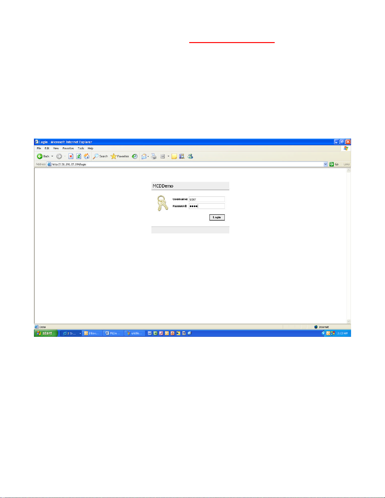
Login Page
The Login Page is where you enter your username (user) and password (pass). Then
click the login icon. Please wait until the booting process completely loads, once it
does, it will automatically route you to the Home Page. Note that the first time you
access your system from any browser it could take several minutes to load the Home
Page. Subsequent access to the system, from the same Personal Computer will load
the Home Page must faster.
McDonald’s HEMS II page 5
Below is the default Login Page from the Local Touch Screen located on the front
of panel after unit has been powered “ON”or after the blank screen has been
touched and unit returns to normal operation mode from power saving standby
mode.
Login Page
The Login Page will be automatically populated with the Username & Password.
Touch the Login icon once and the system will automatically route you to the Home
Page.
McDonald’s HEMS II page 6

Home Page
The Home Page will display your systems current conditions with any active alarms.
McDonald’s HEMS II page 7

Home Page – continued
This area of Home Page shows the following:
1. Your store number and physical location.
2. Current outside air temperature. By touching or clicking on the CYAN colored area you will be
directed to a trend log of accumulated outside temperature data. See page 18 of this document for
more information on this.
3. Current time and date in the control system.
4. By touching or clicking on “Operating Instructions” icon you will be presented with a complete
description and use of each section of displays and completed system electrical drawings and
written sequence of operations. See pages 20-27 and 28-37 of this document for more information
on this.
McDonald’s HEMS II page 8
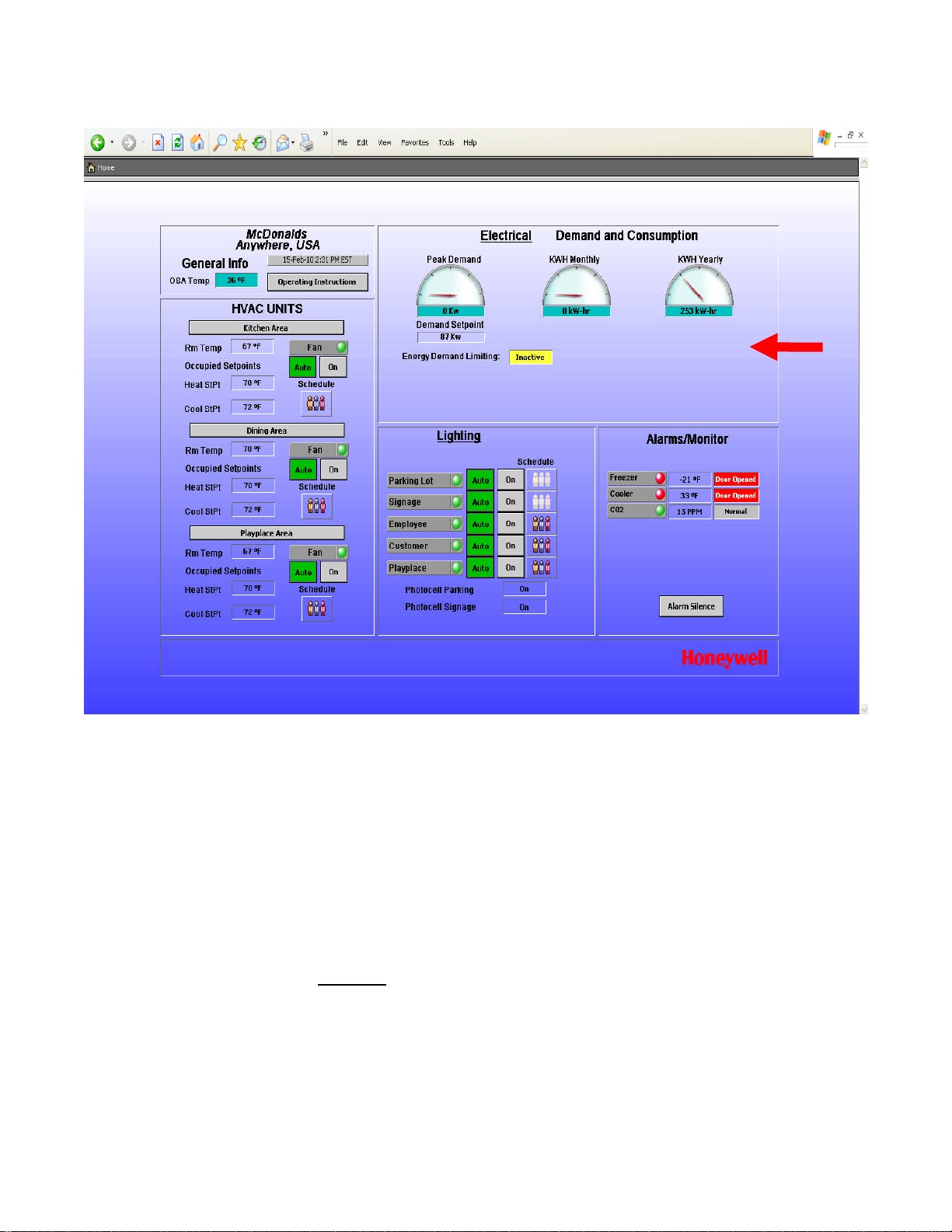
Home Page – continued
This area of Home Page shows the following:
1. Current electrical peak demand and current electrical (KWH) consumption for the current month and
current year. By touching or clicking on any CYAN colored area you will be directed to a trend log of
accumulated electrical data. See page 18 of this document for more information on this.
2. Current electrical demand set point. See page 19 of this document for more information this.
3. Energy Demand Limiting: When active the box will say Active and the background will be RED. When
Inactive the box will say Inactive and the background will be YELLOW. When Active the temperature set
points for all HVAC Units will be automatically raised 3°F (when in cooling mode) or lowered 3°F (when in
heating mode). HVAC Units automatically switch between Cooling/Heating modes to maintain room
temperatures. Active condition exists when current electrical demand is within 2.5% of electrical demand set
point.
4. By touching or clicking on Electrical icon you will be directed to another page for set point adjustments. See
page 19 of this document for more information on this.
McDonald’s HEMS II page 9

Home Page – continued
This area of Home Page shows the following:
1. Current freezer and cooler temperatures. By touching or clicking on any numeric value you will be directed
to a trend log of accumulated freezer or cooler temperature data. See page 18 of this document for more
information on this. RED bullet light (next to Freezer or Cooler) indicates an alarm condition. No alarm
condition and the light will be GREEN. If freezer temperature is 25°F or greater for 5 minutes or more an
alarm condition will exist. If cooler temperature is 42°F or greater for 5 minutes or more and alarm condition
will exist. When in an alarm condition an internal panel alarm horn will sound continuously. Pressing the
Alarm Silence icon causes the internal alarm horn to stop temporarily, yet will start up again if alarm
condition exists after another 5 minutes.
2. Current status of freezer and cooler doors. RED bullet light (next to Freezer or Cooler) indicates an alarm
condition. No alarm condition and the light will be GREEN. Withfreezer or cooler doors closed the
nomenclature to the right will indicate Door Closed with a gray background color. With freezer or cooler
doors open for more than 5 continous minutes the nomenclature will read Door Opened with a RED
background and the internal panel alarm horn will sound continuously. Pressing the Alarm Silence icon
causes the internal alarm horn to stop temporarily, yet will start up again if alarm condition exists after
another 5 minutes.
3. Current bulk C02 reading in parts per million (PPM). RED bullet light (next to CO2) indicates an alarm
condition. GREEN indicates unit is OK. When in alarm condition for more than five minutes (CO2 reading
at 15,000 PPM or greater) an internal panel alarm horn will sound continuously and the NORMAL
nomenclature to the right will change to ALARM with a RED background color. Pressing the Alarm Silence
icon causes the internal alarm horn to stop temporarily, yet will start up again if alarm condition exists after
another 5 minutes. CO2 point information and alarming is an option for the HEMS II panel and may or may
not be included with your system based on what was ordered.
McDonald’s HEMS II page 10
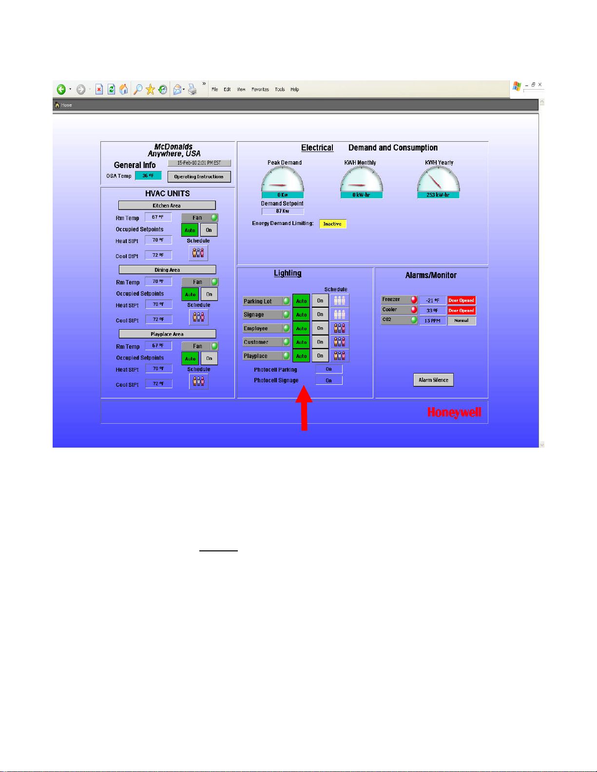
Home Page – continued
This area of Home Page shows the following:
1. Current Lighting controls. RED bullet lights next to a lighting zone name indicates the lighting zone is
commanded OFF by the associated time of day schedule or photocell. GREEN indicates the lighting zone is
commanded ON by the associated time of day schedule or photocell. The photocells and their set points are
only associated with Parking Lot and Signage lighting zones.
2. By touching or clicking on Lighting icon you will be directed to another page for photocell set point
adjustments. See page 19 of this document for more information on this.
3. Each individual lighting zone has a separate AUTO or ON icon. By touching or clicking on the AUTO icon,
that icon will turn GREEN and the associated lighting zone will start and stop based on a time of day
schedule. By touching or clicking on the ON icon that lighting zone will be on continuously.
4. Photocell for Parking and Signage indicate ON when outdoor light level is below the set point for each
lighting zone and OFF when outdoor light level is higher than the set point for each lighting zone. See page 19
of this document for more information on this.
5. There is a separate time of day schedule associated with each lighting zone. Touching or clicking on the
associated schedule icon and you will be automatically routed to another page for schedule adjustments. See
pages 14-17 of this document for more information on this.
6. Schedule icons that show three people (in color) indicate that the schedule is currently in the Occupied Mode
of operations. Schedule icons that show three people (in ghost white) indicate that the schedule is currently in
the Unoccupied Mode of operation.
McDonald’s HEMS II page 11

Home Page – continued
This area of Home Page shows the following:
1. Current HVAC Units. RED bullet lights next to FAN indicate the HVAC Unit is commanded OFF by the
associated time of day schedule. GREEN indicates the HVAC Unit is commanded ON by the associated time
of day schedule.
2. By touching or clicking on Kitchen Area, Dining Area or Playplace Area icons you will be directed to another
page for additional information and set point adjustments. See page 13 of this document for more
information on this.
3. Each individual HVAC Unit has a separate AUTO or ON icon. By touching or clicking on the AUTO icon,
that icon will turn GREEN and the associated HVAC Unit will start and stop based on a time of day schedule.
By touching or clicking on the ON icon that HVAC Unit will be on continuously.
4. There is a separate time of day schedule associated with each HVAC Unit. Touch or Click on the associated
schedule icon and you will be automatically routed to another page for schedule adjustments. See page 14-17
of this document for more information on this.
5. Schedule icons that show three people (in color) indicate that the schedule is currently in the Occupied Mode
of operations. Schedule icons that show three people (in ghost white) indicate that the schedule is currently in
the Unoccupied Mode of operation.
6. Each HVAC Unit shows the current Room Temperature and current Heating and Cooling set points. These
set points are adjustable. Refer to page 13 of this document to make adjustments.
McDonald’s HEMS II page 12
 Loading...