

Page 1

HEGS5000/HEGS5001
Joystick Controller
PTZ, MUX, and VCR Control
User Guide
900.0800 – June 2006 - Rev 1.01
Page 2

ISSUE DATE REVISIONS
900.0394
1.0 February 2006 Initial Release
900.0800
1.0 June 2006 Correct power supply part # and voltage
1.01 June 2006 Correct RS232 wiring
Rev. 1.01 ii 900.0800
19-Jun-06
Page 3
FCC COMPLIANCE STATEMENT
INFORMATION TO THE USER: This equipment has been tested and found to comply
with the limits for a Class A digital device, pursuant to part 15 of the FCC rules. These
limits are designed to provide reasonable protection against harmful interference when
the equipment is operated in a commercial environment. This equipment generates,
uses, and can radiate radio frequency energy and, if not installed and used in
accordance with the instruction manual, may cause harmful interference to radio
communications. Operation of this equipment in a residential area is likely to cause
harmful interference in which case the user will be required to correct the interference at
his own expense.
CAUTION: Changes or modifications not expressly approved by the party responsible
for compliance could void the user’s authority to operate the equipment.
This Class A digital apparatus complies with Canadian ICES-003.
Cet appareil numérique de la Classe A est conforme à la norme NMB-003 du Canada.
USERS OF THE PRODUCT ARE RESPONSIBLE FOR CHECKING AND
COMPLYING WITH ALL FEDERAL, STATE, AND LOCAL LAWS AND
STATUTES CONCERNING THE MONITORING AND RECORDING OF
VIDEO AND AUDIO SIGNALS. HONEYWELL VIDEO SYSTEMS SHALL
NOT BE HELD RESPONSIBLE FOR THE USE OF THIS PRODUCT IN
VIOLATION OF CURRENT LAWS AND STATUTES.
Rev. 1.01 iii 900.0800
19-Jun-06
Page 4

IMPORTANT SAFEGUARDS
1. READ INSTRUCTIONS – All safety and operating instructions should be read before the unit is
operated.
2. RETAIN INSTRUCTIONS – The safety and operating instructions should be retained for future
reference.
3. HEED WARNINGS – All warnings on the unit and in the operating instructions should be adhered
to.
4. FOLLOW INSTRUCTIONS – All operating and use instructions should be followed.
5. CLEANING – Unplug the unit from the outlet before cleaning. Do not use liquid cleaners or
aerosol cleaners. Use a damp cloth for cleaning.
6. ATTACHMENTS – Do not use attachments not recommended by the product manufacturer as
they may result in the risk of fire, electric shock, or injury to persons.
7. WATER AND MOISTURE – Do not use this unit near water or in an unprotected outdoor
installation, or any area which is classified as a wet location.
8. ACCESSORIES - Do not place this product on an unstable cart, stand, tripod,
bracket, or table. The product may fall, causing serious injury to a child or adult and
serious damage to the equipment. Use only with a cart, stand, tripod, bracket, or
table recommended by the manufacturer, or sold with the product. Any mounting of
the product should follow the manufacturer’s instructions and should use a mounting
accessory recommended by the manufacturer. Wall or shelf mounting should follow the
manufacturer’s instructions and should use a mounting kit approved by the manufacturer.
9. A product and cart combination should be moved with care. Quick stops, excessive force, and
uneven surfaces may cause the product and cart combination to overturn.
10. VENTILATION - Slots and openings in the cabinet and the back or bottom are provided for
ventilation and to ensure reliable operation of the equipment and to protect it from overheating.
These openings must not be blocked or covered. The openings should never be blocked by
placing the product on a bed, sofa, rug, or other similar surface. Equipment should never be
placed near or over a radiator or heat register. This product should not be placed in a built-in
installation, such as a bookcase or rack unless proper ventilation is provided or the manufacturer’s
instructions have been adhered to.
11. POWER SOURCES – This product should be operated only from the type of power source
indicated on the marking label. If you are not sure of the type of power supplied to your home,
consult your product dealer or local power company. For products designed to operate from
battery power or other sources, refer to the operating instructions.
12. GROUNDING OR POLARIZATION – The power supply supplied with this unit may be equipped
with a polarized alternating-current line plug (a plug having one blade wider than the other). This
plug will fit into the power outlet only one way. This is a safety feature. If you are unable to insert
the plug fully into the outlet, try reversing the plug. If the plug should still fail to fit, contact your
electrician to replace your obsolete outlet. Do not defeat the safety purpose of the polarized plug.
13. OVERLOADING – Do not overload outlets and extension cords as this can result in a risk of fire or
electric shock.
Rev. 1.01 iv 900.0800
19-Jun-06
Page 5

IMPORTANT SAFEGUARDS
14. POWER-CORD PROTECTION – Power supply cords should be routed so that they are not likely
to be walked on or pinched by items placed upon or against them, paying particular attention to
cords and plugs, convenience receptacles, and the point where they exit from the monitor.
15. OBJECT AND LIQUID ENTRY – Never push objects of any kind into this unit through openings as
they may touch dangerous voltage points or short-out parts that could result in a fire or electric
shock. Never spill liquid of any kind on the unit.
16. SERVICING – Do not attempt to service this unit yourself as opening or removing covers may
expose you to dangerous voltage or other hazards. Refer all servicing to qualified service
personnel.
17. DAMAGE REQUIRING SERVICE – Unplug the unit from the outlet and refer servicing to qualified
service personnel under the following conditions:
a. When the power-supply cord or plug is damaged.
b. If liquid has been spilled, or objects have fallen into the unit.
c. If the unit has been exposed to rain or water.
d. If the unit does not operate normally by following the operating instructions. Adjust only those
controls that are covered by the operating instructions as an improper adjustment of other
controls may result in damage and will often require extensive work by a qualified technician to
restore the unit to its normal operation.
e. If the unit has been dropped or the enclosure has been damaged.
f. When the unit exhibits a distinct change in performance - this indicates a need for service.
18. REPLACEMENT PARTS – When replacement parts are required, be sure the service technician
has used replacement parts specified by the manufacturer or have the same characteristics as the
original part. Unauthorized substitutions may result in fire, electric shock or other hazards.
19. SAFETY CHECK – Upon completion of any service or repairs to this unit, ask the service
technician to perform safety checks to determine that the unit is in proper operating condition.
20. LIGHTNING AND POWER LINE SURGES – For added protection of this unit during a lightning
storm, or when it is left unattended and unused for long periods of time, unplug it from the wall
outlet and disconnect the cable system. This will prevent damage to the unit due to lightning and
power-line surges.
21. HEAT – The product should be situated away from heat sources such as radiators, heat registers,
stoves, or other products (including amplifiers) that produce heat.
22. INSTALLATION – Do not install the unit in an extremely hot or humid location, or in a place
subject to dust or mechanical vibration. The unit is not designed to be waterproof. Exposure to
rain or water may damage the unit.
23. WALL OR CEILING MOUNTING – The product should be mounted to a wall or ceiling only as
recommended by the manufacturer
Rev. 1.01 v 900.0800
19-Jun-06
Page 6
EXPLANATION OF GRAPHICAL SYMBOLS
The lightning flash with arrowhead symbol within an equilateral triangle is intended to
alert the user to the presence of uninsulated "dangerous voltage" within the product's
enclosure that may be of sufficient magnitude to constitute a risk of electric shock to
persons.
The exclamation point within an equilateral triangle is intended to alert the user to the
presence of important operating and maintenance (servicing) instruction in the literature
accompanying the product.
CAUTION
CAUTION
RISK OF ELECTRIC SHOCK
DO NOT OPEN
CAUTION: TO REDUCE THE RISK OF ELECTRIC SHOCK,
DO NOT REMOVE COVE R (OR BACK).
NO USER-SERVICEABLE PARTS INSIDE.
REFER SERVICING TO QUALIFIED SERVICE PERSONNEL.
WARNING
WARNING: TO REDUCE THE RISK OF FIRE OR ELECTRIC SHOCK, DO
NOT EXPOSE THIS PRODUCT TO RAIN OR MOISTURE.
WARNING: DO NOT INSERT ANY METALLIC OBJECT THROUGH
VENTILATION GRILLS THIS PRODUCT TO RAIN OR MOISTURE.
WARNING: THIS UNIT MUST BE OPERATED WITH A PROPERLY
GROUNDED 3-PIN CONNECTION.
NON-OBSERVANCE OF THIS STANDARD PRACTICE MAY RESULT IN A
STATIC ELECTRICITY BUILD-UP THAT MAY RESULT IN AN ELECTRIC
SHOCK WHEN EXTERNAL CONNECTIONS ARE TOUCHED.
Rev. 1.01 vi 900.0800
19-Jun-06
Page 7

TABLE OF CONTENTS
SECTION 1: INTRODUCTON ...................................................................................................................1
1.1
PRODUCT DESCRIPTION ............................................................................................................ 1
1.2
FEATURES.................................................................................................................................... 1
1.3
ADDITIONAL INFORMATION........................................................................................................ 1
SECTION 2: INSTALLATION AND EQUIPMENT SETUP......................................................................... 3
2.1
CONNECTIONS............................................................................................................................ 3
2.2
INSTALLATION DIAGRAMS.......................................................................................................... 4
2.3
EQUIPMENT SETUP..................................................................................................................... 7
2.3.1 KD6/HD6 Setup ............................................................................................................... 7
2.3.2 Multiplexer Setup............................................................................................................. 7
2.3.3 VCR Setup .......................................................................................................................7
SECTION 3: MODES OF OPERATION..................................................................................................... 9
3.1
MODES OF OPERATION.............................................................................................................. 9
3.2
MODE CONFIGURATION............................................................................................................. 9
3.3
POWER-UP .................................................................................................................................10
3.3.1 Default Password........................................................................................................... 11
3.3.2 Default User Defined Settings........................................................................................ 11
3.3.3 LCD Display ................................................................................................................... 11
3.3.4 Log Out .......................................................................................................................... 12
SECTION 4: SYSTEM SETUP................................................................................................................. 13
4.1
SETTING UP THE CONTROLLER ..............................................................................................13
4.2
NAVIGATING THE MENUS......................................................................................................... 13
4.3
MENUS ....................................................................................................................................... 14
SECTION 5: STANDALONE MODE HEGS5000..................................................................................... 19
5.1
OPERATION................................................................................................................................19
5.1.1 Camera (KD6/HD6) Selection........................................................................................ 20
5.1.2 Manual Control .............................................................................................................. 20
5.2
KD6/HD6 DOME MENUS ........................................................................................................... 22
5.2.1 Dome Setup Menu......................................................................................................... 23
5.2.2 Program PreShot ........................................................................................................... 25
5.2.3 Recall PreShot ............................................................................................................... 28
5.2.4 List Programmed PreShots ........................................................................................... 29
5.2.5 Programming a VectorScan .......................................................................................... 30
5.2.6 Run VectorScan............................................................................................................. 31
5.2.7 List VectorScans ............................................................................................................ 32
Rev. 1.01 vii 900.0800
19-Jun-06
Page 8

TABLE OF CONTENTS, CONTINUED
5.2.8 List VectorScan Contents .............................................................................................. 32
5.2.9 Program a Tour.............................................................................................................. 33
5.2.10 Run a Tour ..................................................................................................................... 33
5.2.11 Delete a Tour .................................................................................................................34
5.2.12 Programming Sector IDs ............................................................................................... 34
5.2.13 Programming/Editing/Deleting Privacy Zones .............................................................. 36
5.2.13.1 Programming/Editing/Deleting Privacy Zones, Sony Camera .......................36
5.2.13.2 Programming/Editing/Deleting Privacy Zones, Hitachi Camera..................... 39
5.2.13.3 Changing the Privacy Zone Password............................................................41
5.2.14 Nightshot Mode ............................................................................................................. 42
SECTION 6: MUX MODE OPERATION HEGS5001............................................................................... 43
6.1
INTRODUCTION ......................................................................................................................... 43
6.2
SPOT MONITOR OPERATION ................................................................................................... 44
6.2.1 Absolute Mode............................................................................................................... 45
6.2.2 Relative Mode ................................................................................................................ 45
6.3
MULTIPLEXER CONTROL.......................................................................................................... 46
6.4
VCR CONTROL........................................................................................................................... 47
SECTION 7: DOWNLOADING NEW FIRMWARE TO THE HEGS5000..................................................49
7.1
INTRODUCTION ......................................................................................................................... 49
7.2
CONNECTING THE HEGS5000/HEGS5001 TO YOUR PC ....................................................... 49
SECTION 8: TROUBLESHOOTING AND MAINTENANCE.................................................................... 55
8.1
TROUBLESHOOTING................................................................................................................. 55
8.2
DIAGNOSTICS............................................................................................................................ 55
8.2.1 Joystick Test Modes...................................................................................................... 55
8.3
SERVICING THE CONTROLLER ................................................................................................ 56
8.4
PREVENTIVE MAINTENANCE.................................................................................................... 56
SECTION 9: SPECIFICATIONS.............................................................................................................. 57
LIST OF FIGURES
Figure 1: Installing Honeywell Multiplexer, VCR, and Domes ....................................................................... 4
Figure 2: Connection Diagram 1.................................................................................................................... 5
Figure 3: Connection Diagram 2.................................................................................................................... 6
Figure 4. LCD ................................................................................................................................................. 11
Figure 5. HEGS5000 English Text Overlay.................................................................................................... 19
Rev. 1.01 viii 900.0800
19-Jun-06
Page 9
LIST OF FIGURES, CONTINUED
Figure 6. HEGS5000 Icon Overlay................................................................................................................. 19
Figure 7. MUX Mode English Text Version .................................................................................................... 43
Figure 8. MUX Mode Icon Version................................................................................................................. 43
Figure 9: Ultrak Code Server Window ...........................................................................................................50
Figure 10: CommPort Properties Window..................................................................................................... 50
Figure 11: Enabling the CommPort ............................................................................................................... 51
Figure 12: Invalid Port Error........................................................................................................................... 51
Figure 13. Transmit Hex File .......................................................................................................................... 51
Figure 14: Send Hex File Window ................................................................................................................. 52
Figure 15: Selecting the Hex File to Send ..................................................................................................... 52
Figure 16: Sending Hex File Status Window ................................................................................................. 53
Figure 17. Transfer Complete ........................................................................................................................ 53
LIST OF TABLES
Table 1. Manual Control................................................................................................................................. 20
1. ___
Table 2. DOME MENU (
3. ___
) Key – Access/Exit Dome Menus................................................................... 22
Rev. 1.01 ix 900.0800
19-Jun-06
Page 10

Notes:
Rev. 1.01 x 900.0800
19-Jun-06
Page 11
INTRODUCTON
1.1 PRODUCT DESCRIPTION
The HEGS5000 is a controller designed to provide simple operation of the Honeywell
KD6/HD6 series domes, VCRs, and multiplexers: 16 multiplexers, 16 VCRs and 256
domes can be controlled via the HEGS5000’s two serial ports. All functions of the
individual units are supported remotely and intelligently.
1.2 FEATURES
The HEGS5000 controller includes the following features:
• Integrated control of Domes, VCRs, and Multiplexers.
• Control of up to 256 Honeywell KD6/HD6 domes
• Remote control of up to 16 Honeywell KR4XXXXX Series VCRs.
• Remote control of up to 16 Honeywell AXCD or AXMD series, HXCT or HXMT
series, KX16XXCX series, KQ7300CX, KX04XXCX and KX09XXCX multiplexers.
SECTION 1:
• LCD Display
• Separate logins for Operators and Master Users (supervisors)
1.3 ADDITIONAL INFORMATION
CAUTION: Users of this product are responsible for
checking and complying with all federal, state, and local
laws and statutes concerning the monitoring and
recording of video and audio signals. Honeywell shall
not be held responsible for the use of this product in
violation of current laws and statutes.
Rev. 1.01 1 900.0800
19-Jun-06
Page 12

Notes:
Rev. 1.01 2 900.0800
19-Jun-06
Page 13
INSTALLATION AND EQUIPMENT SETUP
2.1 CONNECTIONS
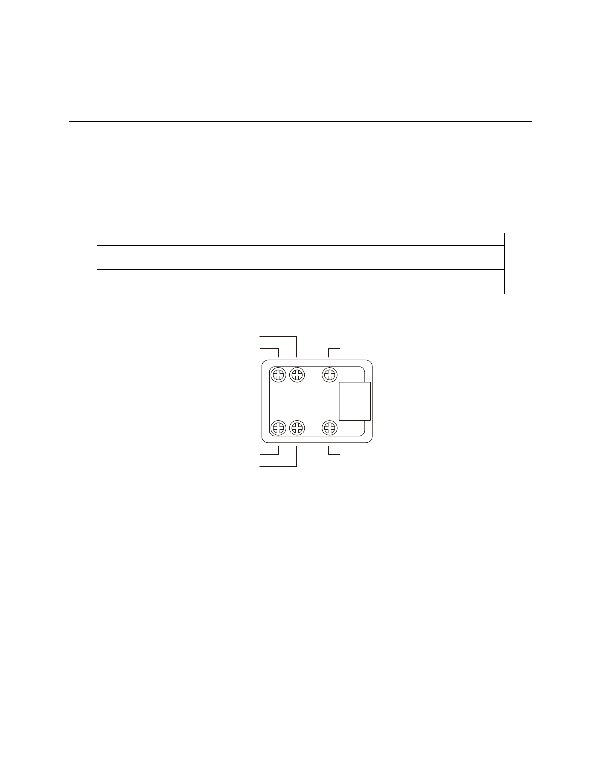
A terminal block is provided for connection between the HEGS5000 controller and
peripheral equipment. A coiled cable is provided for connection between the
HEGS5000 and the terminal block. Plug one end of the coiled cable into the connector
on the back of the HEGS5000 and the other end into the jack on the terminal block.
Power Supply Connect the power supply, part number 849193-0089,
COM1 (RS485 output port) Used for controlling Honeywell KD6/HD6 series domes.
COM2 (RS232 serial port) Used for controlling Honeywell multiplexers and VCRs.
SECTION 2:
Description
provided with the unit.
GND
+12VDC
RS-232 (TX) - COM2
RS-485 (D-) - COM1
RS-485 (D+) - COM1
RS-232 (RX) - COM2
Refer to Section 2.2 for installation diagrams for connection to Multiplexers, VCRs, etc.
Rev. 1.01 3 900.0800
19-Jun-06
Page 14
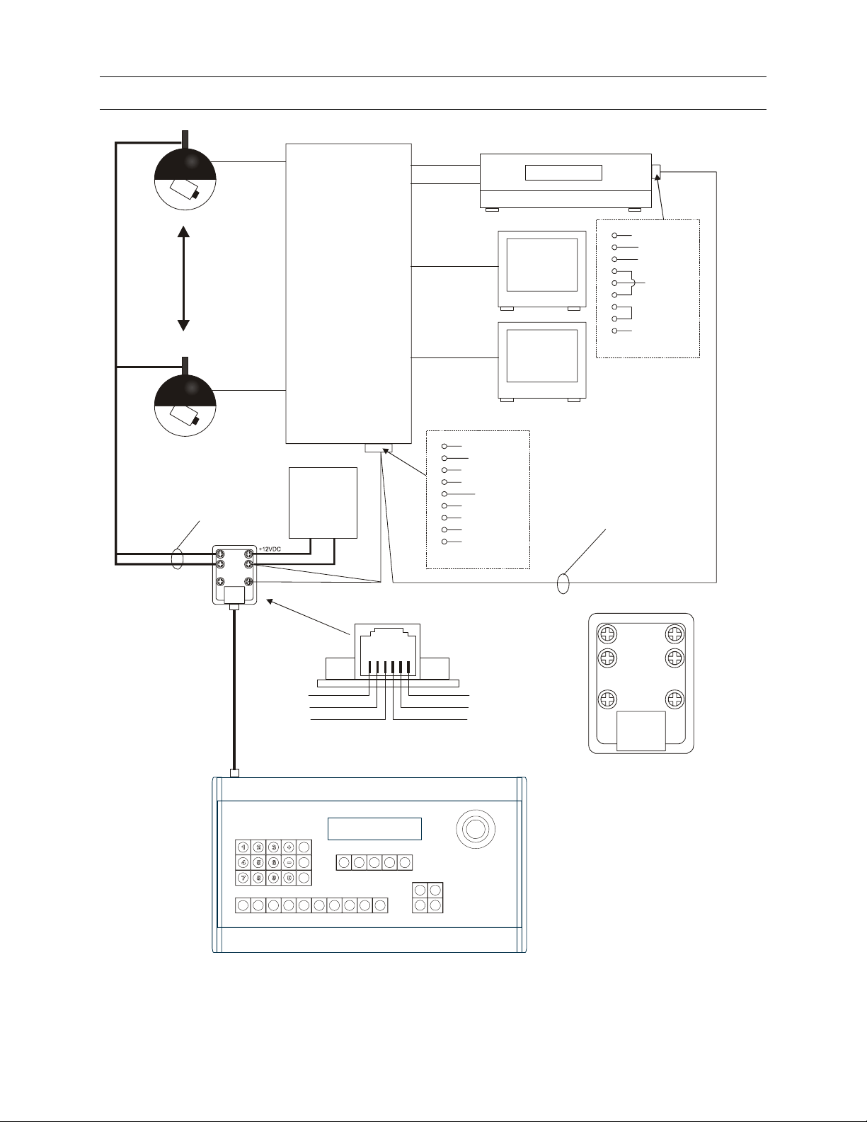
2.2 INSTALLATION DIAGRAMS
r
Part #849193-0089
RS-485
KX1610CN Multiplexe
Cam 1
Cam 16
2 - RX (data in)
5 - Ground
PSU
12 VDC
2A
-
+
GND
Output
RS-232
Input
Spot
Main
1
2
3
4
5
6
7
8
9
DB9-Male
Input
Output
RX (Data In)
GND
Spot
Monitor
Main
Monitor
VCR
2 - RX (data in)
5 - Ground
RS-232
1
2
RX (Data In)
3
4
5
GND
6
7
8
9
DB9-Female
RS-232
R232 TXS
RS-232 (RX)
RS-485 (D+)
RS-485 (D-)
HEGS5000 System Controller
RS-232 (TX)
GND
+12VDC
RS-485 (D-)
RS-485 (D+)
+12VDC
GND
RS-232 (TX)RS-232 (RX)
Figure 1: Installing Honeywell Multiplexer, VCR, and Domes
Rev. 1.01 4 900.0800
19-Jun-06
Page 15
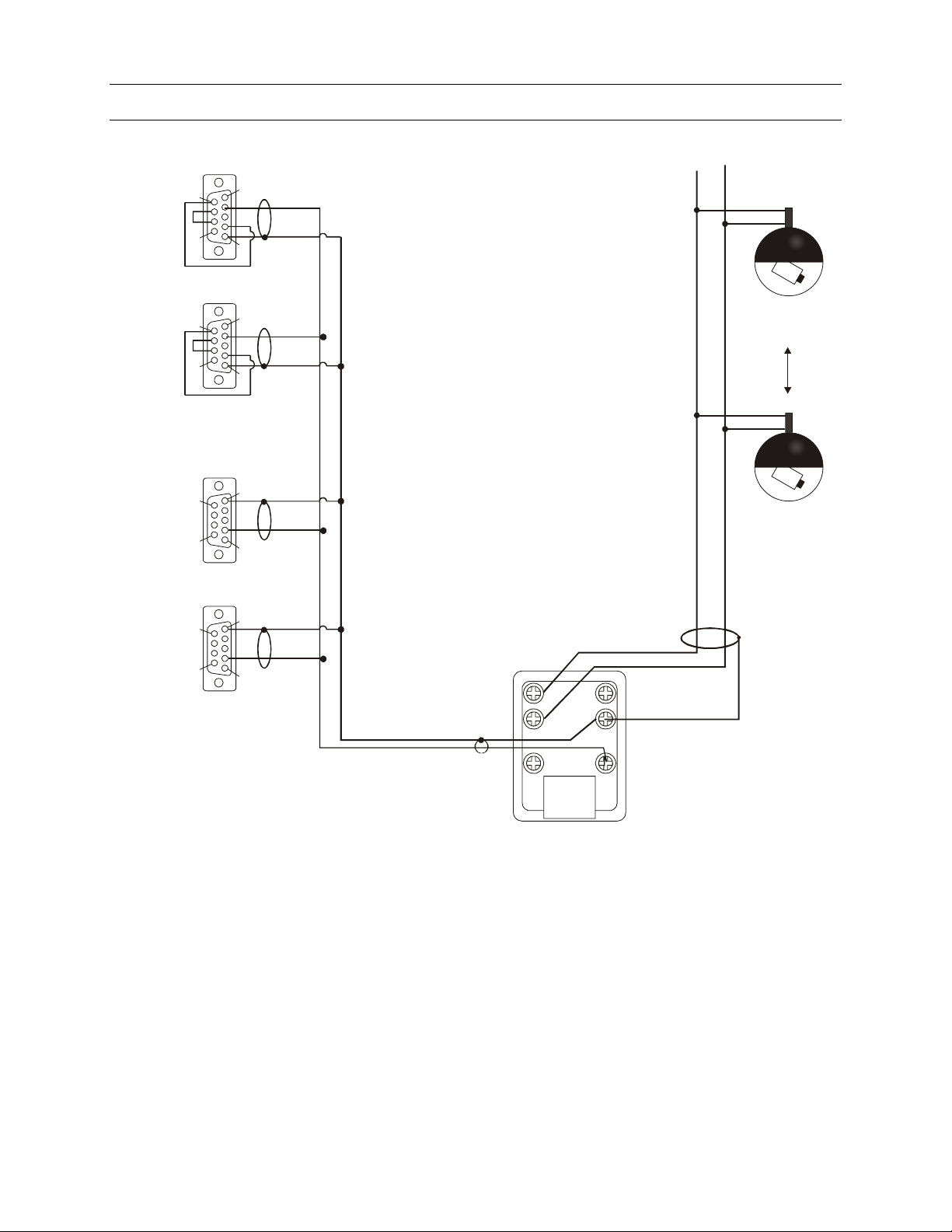
2.2 INSTALLATION DIAGRAMS, CONTINUED
1
6
VCR 2
rear vi ew of connecto r
VCR 1
rear vi ew of connecto r
Multiplexer 2
rear vi ew of connecto r
Multiplexer 1
rear vi ew of connecto r
9
DB-9 Female
6
9
DB-9 Female
9
6
DB-9 Male
9
6
DB-9 Male
5
1
KD6 / KD6Z
Dome -32
5
5
KD6 / KD6Z
1
5
1
RS-485 (D-)
RS-485 (D+)
+12VDC
GND
Dome - 1
RS-232 (RX)
RS-232 (TX)
Figure 2: Connection Diagram 1
Rev. 1.01 5 900.0800
19-Jun-06
Page 16
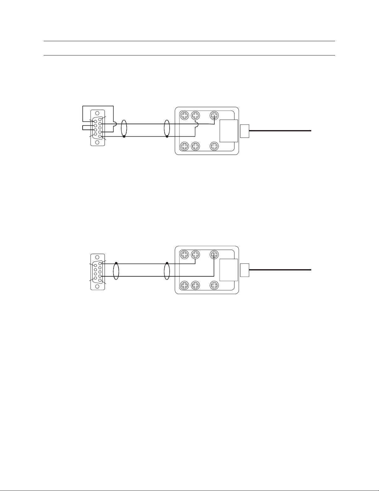
2.2 INSTALLATION DIAGRAMS, CONTINUED
RS-232
to VCR
RS-232
to MUX
6
9
DB-9 Female
rear view of connector
9
6
1
5
5
1
+12VDC+12VDC
RS-485 (D-)RS-485 (D-)
RS-485 (D+ )RS-485 (D+)
RS-232 VCR cable connections
RS-232 (TX)RS-232 (TX) RS-232 (RX)RS-232 (RX)
GNDGND
To HEGS5000
To HEGS5000
DB-9 Male
rear view of connector
RS-232 MUX cable connections
Figure 3: Connection Diagram 2
Rev. 1.01 6 900.0800
19-Jun-06
Page 17

2.3 EQUIPMENT SETUP
2.3.1 KD6/HD6 Setup
The KD6/HD6 Dome must be set to Honeywell Diamond protocol. The address of the
KD6/HD6 dome must be set to match the address set for that camera number in the
HEGS5000. That is, the KD6/HD6 camera defined as camera 1 in the HEGS5000 system
setup must be physically addressed 001 using the rotary switches on the KD6/HD6
receiver board.
Refer to the KD6 or HD6 Series User Manual for switch settings and detailed operation.
2.3.2 Multiplexer Setup
The multiplexer should be set up as follows:
Communication: RS232
Baud: 1200
The address of the multiplexer with cameras 1-16 must be set at 1, cameras 17 –32 set
at 2. See the multiplexer user manual for more details.
2.3.3 VCR Setup
The VCR address is set to NONE as the default. To function properly, VCR 1 must be
set to address 1 and VCR 2 to address 2. See the VCR user manual for more details.
Rev. 1.01 7 900.0800
19-Jun-06
Page 18

Notes:
Rev. 1.01 8 900.0800
19-Jun-06
Page 19
MODES OF OPERATION
3.1 MODES OF OPERATION
There are two modes of operation when using the HEGS5000 as a standalone controller:
1. HEGS5000 = Standalone = PTZ control (KD6/HD6 and KDZ series) only. Note:
KDZ series domes have been discontinued.
2. HEGS5001 = MUX Mode = MUX/VCR control capability and PTZ control
There is a third mode of operation that is only for use with the HSX3208L Matrix Video
Switcher.
3. HEGS5002 = System = HSX3208L Switcher. Refer to the HSX3208L Switcher User
Manual for setup and operation of the HEGS5000 in System mode.
The default configuration is Standalone mode (PTZ control only). To change the
configuration, refer to Section 3.2
SECTION 3:
3.2 MODE CONFIGURATION
To configure the HEGS5000 mode of operation, perform the following steps.
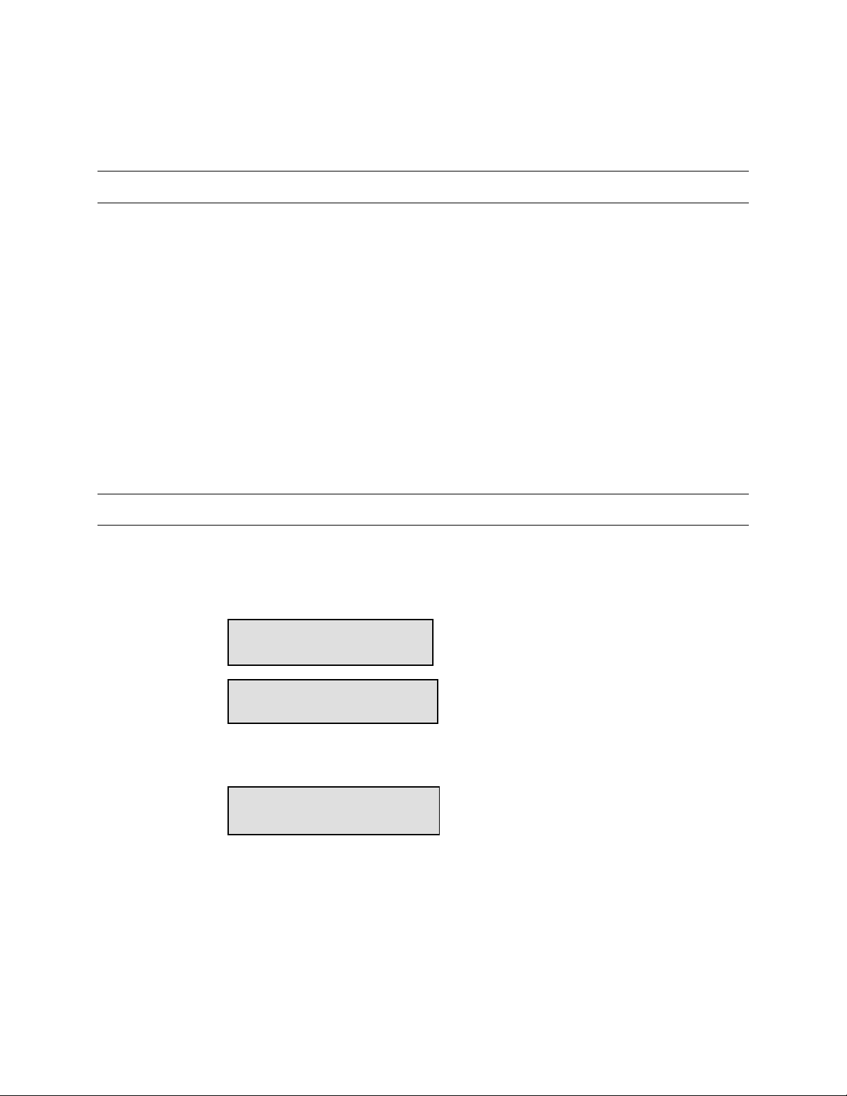
1. Power-up the HEGS5000. The following messages are displayed on the LCD
display.
2. Before the unit counts down to 0, press 1. The LCD displays:
Note: The current configuration is displayed with ** on both sides as shown above.
Boot Mngr MMDDYY
519685-1980 A
Booting in 5s
< Run Bank >
** Standalone **
Rev. 1.01 9 900.0800
19-Jun-06
Page 20
3.2 MODE CONFIGURATION, CONTINUED
3. Press or keys to scroll through the available options.
• Standalone (control KD6/HD6 PTZs only)
• Mux Mode (control multiplexers, VCRs, and KD6/HD6 PTZs)
• System Mode (must be used with HSX3208L switcher)
• Stdalone/Mux Fw. (upload new firmware to the HEGS5000). Refer to Section 7
for uploading the latest firmware.
• System Firmware (upload new firmware to the HEGS5000 system controller).
Refer to the HSX3208L User Manual to upload the latest firmware.
4. When the desired option is displayed, press Enter (
booting for the selected mode.
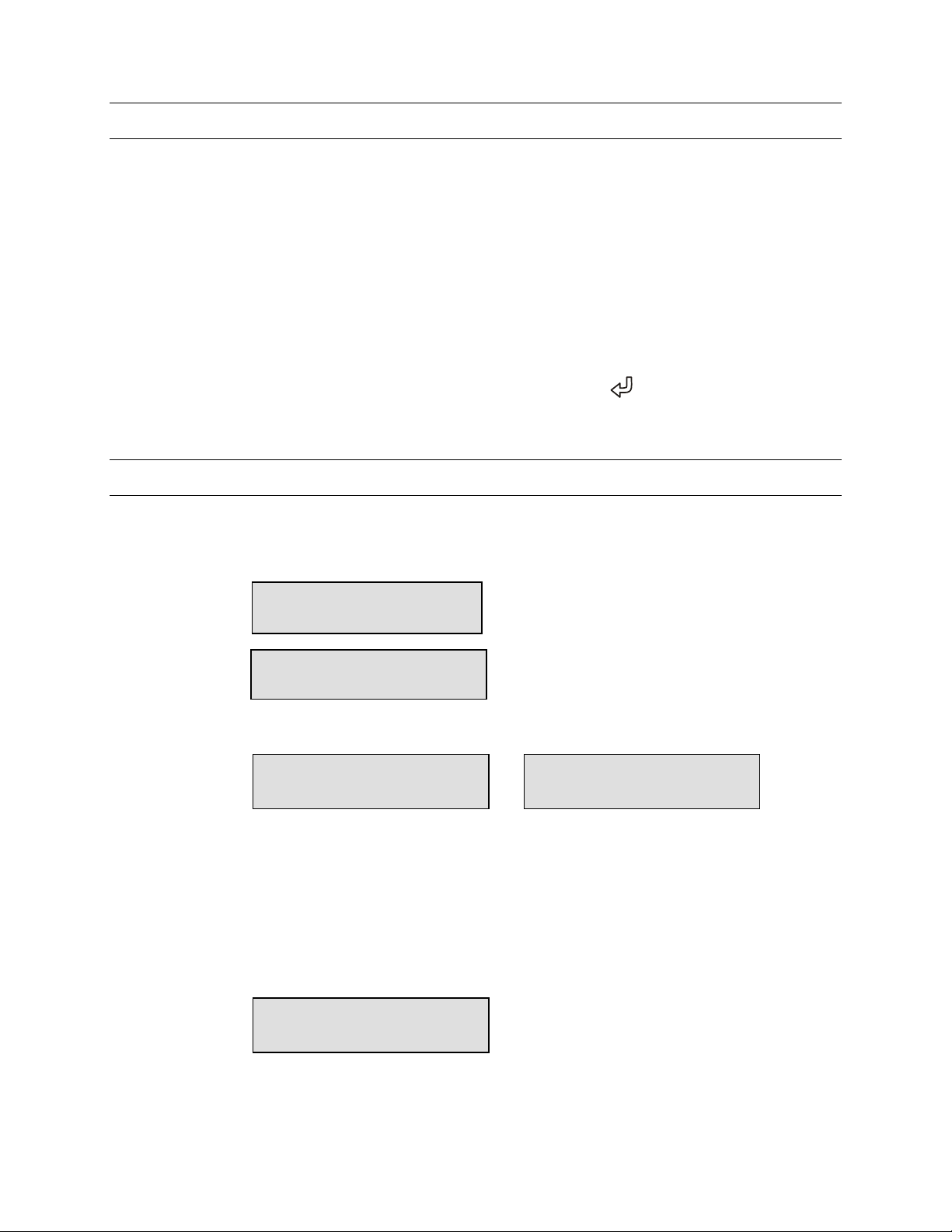
3.3 POWER-UP
The power-up process is the same for both the MUX mode and the Standalone mode of
operation. When power is applied to the HEGS5000, the LCD displays the following
messages:
Booting in 5s
After 5 seconds, the current application starts. The selected mode (HEGS5000 or
HEGS5001) is displayed.
Boot Mngr MMDDYY
519685-1980 A
HEGS5000 MMDDYY
519686-1980 A
). The controller continues
(counts down to 0)
HEGS5001 MMDDYY
519686-1980 A
Note: if the configuration has been changed by the user, this screen displays,
“Loaded Saved Configuration”
Then the login screen in displayed.
Two levels of login are available: Master and Operator.
System login
Password: _ _ _ _
Enter the four-digit password to logon. Refer to paragraph 3.3.1 for default passwords.
Rev. 1.01 10 900.0800
19-Jun-06
Page 21
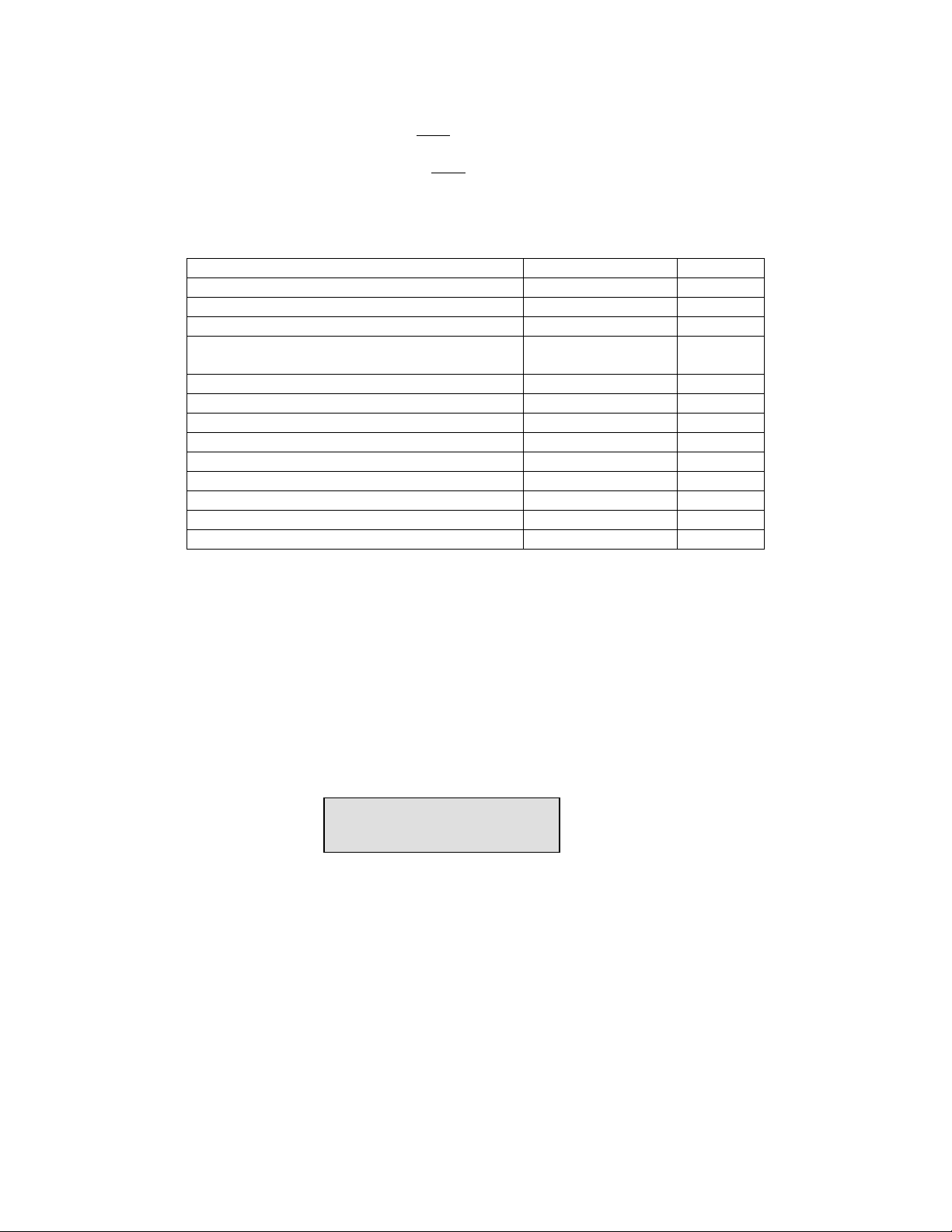
3.3.1 Default Password
Master Default Password is 1994.
Operator Default Password is
Master mode has access to all menus. Operator mode allows access to all menus
except those in which changes to system setup are involved. The table below shows
which menus and functions are available for each mode.
Description Operator Master
Save PreShot - KD6/HD6 domes 1-10 Only Yes
Recall PreShot on KD6/HD6 domes Yes Yes
Programming a VectorScan - KD6/HD6 domes No Yes
Running a programmed VectorScan – KD6/HD6
dome
Programming a tour menu – KD6/HD6 dome No Yes
Running a tour – KD6/HD6 dome Yes Yes
NightShot On/Off –KD6/HD6 Yes Yes
Auto iris on/off – KD6/HD6 Yes Yes
Programming a sector – KD6/HD6 No Yes
Programming a privacy zone – KD6/HD6 No Yes
Access to the KD6/HD6 dome setup menu No Yes
Access to the System Setup Menu No Yes
Access to the multiplexer setup menu No Yes
3.3.2 Default User Defined Settings
To return the controller to the user-defined default settings, perform the following steps.
1111.
Yes Yes
1. Power the unit down and back up.
2. When the LCD display shows the controller is Booting Run Menu key during the 5second booting process.
3.3.3 LCD Display
In the above display, the HEGS5000 is configured for MUX mode of operation. Spot01
is the Spot Monitor and Multiplexer the controller is currently controlling. This will
change if you have more than one multiplexer in your system. Spot 01 is the spot
monitor for multiplexer one; Spot 02 is the spot monitor for multiplexer two, etc. Refer to
section 6 for MUX operation.
Cam001 is the camera currently being controlled.
If the controller is configured for Standalone mode of operation; the Spot monitor is not
displayed.
<Spot01 Cam001>
Figure 4. LCD
Rev. 1.01 11 900.0800
19-Jun-06
Page 22

3.3.4 Log Out
To log off the controller, perform the following steps.
1. Press the Run Menu (
Run
1. ___
3. ___
) key until Logout is displayed on the LCD display.
2. Press Enter (
3. Press Enter (
). Yes is displayed on the LCD display.
) to select Yes or press Menu ESC (
1. ____
2. ____
3. ____
) to cancel logging out.
The LCD display returns to the login password.
System login
Password: _ _ _ _
Rev. 1.01 12 900.0800
19-Jun-06
Page 23

SECTION 4:
s
SYSTEM SETUP
4.1 SETTING UP THE CONTROLLER
The components controlled by the HEGS5000 are defined in the SYSTEM MENU. This
menu is available only when logged in as a Master User.
• The SYSTEM MENU is in tree structure.
• Several tools, including the LEFT () and RIGHT () keys, Enter key (
the UP ()and DOWN () functions on the joystick are used to navigate
through the menus.
• Press Enter ( ) or Zoom In (clockwise) to select an option and go down one
level.
• Press Clear/Manual ( ) or Zoom Out (counterclockwise) to go back one
step or up one menu level.
4.2 NAVIGATING THE MENUS
To access the System Setup, press the System Menu (
The LCD screen will indicate the level, menu name, and additional options.
Note: If the controller is set for
Standalone Mode, the menus start
with the Camera Menu (Level [3.0])
Using the figure, the LCD shows that
the controller is at the Multiplexer Menu, which is menu 1. More indicates that there are
more options or submenus available under this menu.
), and
Sy
1. ___
3. ___
) key.
Mux’s [1.0]
More
• To select this menu, press Enter (
• To move to another menu, use the joystick tilt up and tilt down functions.
Moving the joystick up will change it to menu 2, then menu 3, and so on. You
can view the menus in reverse order by moving the joystick down.
• If you have selected a menu incorrectly, press Clear/Manual (
Out” to return to the previous level.
• Once in a submenu, use the joystick or the Enter (
the available options.
Rev. 1.01 13 900.0800
19-Jun-06
).
) or “Zoom
) key to navigate through
Page 24

4.2 NAVIGATING THE MENUS, CONTINUED
• To exit the System Menu, use the joystick to choose menu 8 (Exit), then press
4.3 MENUS
Menu Name Menu
Mux’s 1.0 Used to set the type of multiplexer and the number of
Mux type 1.1 Type of Multiplexers – only one type of multiplexer per
No. of Muxes 1.2 Number of Multiplexers – 1 to 16 allowed. Each
Enter (
menu, the controller displays Saving Settings, Please Wait. After the settings
have been saved, the controller returns to normal operation.
) or “Zoom Out” until the setup menu is exited. When you exit a
Multiplexers
Description
Number
multiplexers in the system. Press Enter (
this menu.
system (KX16xxCX, KQ7300Cx, KX04xxCx, KX09xxCx,
KXR23xxU, KX1630CU, MXXD9E, MXXD16E supported).
Note: Use KX16xxCX, KX04xxCx, or KX09xxCx for
KX16xxMX, KX04xxMx, or KX09xxMx respectively. For
AXCD, AXMD, HXCT, or HXMT series multiplexers, use
MXXD9E or MXXD16E depending on the number of
channels (9 or 16).
Press Enter (
multiplexer must have the address set at its logical
).
) to access
number. Press Enter (
Recorders
Menu Name Menu
Number
Recorders 2.0 Used to set the type of VCR and the number of VCR’s in
the system. Press Enter (
VCR Type 2.1 Type of VCR – Only one type of VCR per system
(KR4xxxCx). Press Enter (
No. of VCRs 2.2 Number of VCR’s – 1 to 16 allowed -each VCR must
have the address set at its logical number. Press Enter
) or joystick tilt down to move to the next submenu.
(
Press Clear/Manual (
Rev. 1.01 14 900.0800
19-Jun-06
).
Description
) to access this menu.
).
) to exit this menu.
Page 25

4.3 MENUS, CONTINUED
Cameras
Menu Name Menu
Number
Cameras 3.0 Used to set the type of camera and the address to
which the controller sends commands when this camera
is selected on the monitor or spot monitor if the
Description
controller is in Mux Mode . Press Enter (
this menu.
Camera Num 3.1
(Cam Num) Type 3.1.1 Used to select the type of camera for each camera
Tip: To make it easy to setup camera TYPES and camera ADDRESSES, start with Camera 1
TYPE and simply press Enter (
and then press Enter (
ADDRESS for each subsequent camera until all cameras are done.
(Cam Num) Address 3.1.2 Used to set the camera address. The camera number in
) to move to the TYPE for camera 2. Continue setting the TYPE and
Camera Number – use the number keys or the
keys to select the camera number.
Once the camera number is selected, press Enter (
to move to the next submenu.
number. The camera number in parentheses indicates
which camera is currently selected.
To set camera type, use the
between the four camera types (KD6/HD6, KD6-Z, Fixed
Camera, and Pan Tilt Head).
Press Enter (
next submenu.
) after setting the type to go to the address. Set the address
parentheses indicates which camera is selected.
Enter the required address of the camera using the
number keys or the
the address must be the same as the value set in menu
5.0 setup.
) or joystick tilt down to move to the
+
+
and – keys to select
and – keys. For KD6-Z domes,
) to access
+
and
–
)
Press Enter (
Press Clear/Manual (
Rev. 1.01 15 900.0800
19-Jun-06
) to move to the next camera.
) to exit this menu.
Page 26

4.3 MENUS, CONTINUED
KDZ SETUP
Menu Name Menu
Number
KDZ Setup 4.0 Used to program the address of any KDZ connected to
Description
the HEGS5000. Press Enter (
Serial No. 4.1 Using the number keys, enter the serial number of the
KDZ dome. Press Enter (
supplied with the dome and is printed on the dome.
KD6-Z Addr 4.2 Enter the required address of the dome using the
+
number keys or
Set Address 4.3
Note: The above setup menu is simply a tool to allow the address of the KDZ dome to be
programmed from the controller. This information is not stored in the controller.
The address of each KDZ dome can be set one after each other without having to
exit this menu. Refer to the KDZ User Manual for detailed information on
programming and controlling a KDZ camera.
Menu Name Menu
Number
Passwords 5.0
Master 5.1 Enter a new 4-digit master password. Once the digits
Operator 5.2 Enter a new 4-digit operator password. Once the
Menu Name Menu
Number
Outputs 6.0 An additional mutiplexer can be used to combine the
Press Enter (
the serial number and address to reprogram the KD6-Z
dome. Press Clear/Manual (
Passwords
Press Enter (
are entered, the password is reset.
digits are entered, the password is reset. Press
Clear/Manual (
Outputs
monitor outputs of multiple multiplexers to one monitor.
and – keys. Press Enter ( ).
) to confirm the information and send
Description
) to access this menu.
) to exit this menu.
Description
) to access this menu.
). The serial number is
) to exit this menu.
Press Enter (
Switch Dev 6.1
Address 6.2 Enter the address of the output using the number keys
Rev. 1.01 16 900.0800
19-Jun-06
Switch Device – use the
type of multiplexer used to combine the monitor
outputs.
Press Clear/Manual (
or the
+
and – keys (001 to 255).
) to access this menu.
+
and – keys to select the
) to exit this menu.
Page 27

4.3 MENUS, CONTINUED
General
Menu Name Menu
Number
General 7.0 Used to deactivate the buzzer or set language options.
Description
Press Enter (
Buzzer 7.1
Language 7.2 Menus are currently only available in English. Use
Menu Name Menu
Number
Exit 8.0
Use the
Press Clear/Manual (
the
options.
Press Clear/Manual (
Press Enter(
press the System Menu key or the Clear/Manual
(
+
+
and – keys to scroll through the language
Exit
) key to exit the system menu.
) to access this menu.
and – keys to toggle the buzzer ON or OFF.
) to exit this menu.
) to exit this menu.
Description
) to exit the Setup Mode. You can also
Rev. 1.01 17 900.0800
19-Jun-06
Page 28

Notes:
Rev. 1.01 18 900.0800
19-Jun-06
Page 29

5.1 OPERATION
V
When the HEGS5000 Controller is in Standalone Mode, a user can control and program
KD6/HD6 PTZ cameras. The KD6/HD6 PTZ cameras must be defined in the HEGS5000
as defined in Section 2.3.1 and 4.3.
There are two overlays, English text version and Icon version, for the standalone mode.
System Controller HEGS5000
SECTION 5:
STANDALONE MODE
HEGS5000
Iris
Open
Iris
Close
Focus
Auto
Near
Iris
System Controller HEGS5000
A
Camera
Character
Select
Monitor
Menu
ESC
Enter
Freeze
Video
Run
Menu
Dome
Menu
System
Menu
Figure 5. HEGS5000 English Text Overlay
Run
ABC
1. ____
2. ____
3. ____
1. ___
3. ___
1. ___
3. ___
Sys
1. ___
3. ___
PreShot
ectorScan
Figure 6. HEGS5000 Icon Overlay
All instructions are given using the text overlay with the Icon overlay in parenthesis.
Note: The Monitor Key (
1. ____
2. ____
Esc (
3. ____
)key. All cameras must have dedicated monitors.
) is not used in the standalone mode except as a Menu
Rev. 1.01 19 900.0800
19-Jun-06
Page 30

5.1.1 Camera (KD6/HD6) Selection
To select a camera for control:
1. Enter the camera number (1-256) using the numeric keypad.
2. Press the Camera (
) key.
5.1.2 Manual Control
Table 1. Manual Control
Function Description
Pan/Tilt Use the joystick to control (pan and tilt) the camera. Move the joystick
up and down for tilt functions and left and right for pan functions.
Zoom Rotate the joystick knob clockwise/counterclockwise for zoom in/out
functions.
Iris
Focus
Run Menu (
Run
1. ___
3. ___
Press the Auto Iris (
Press the Iris Open (
Press the Iris Close (
Press the Focus Near (
focus the lens.
)
The Run Menu (
certain features of the KD6/HD6 PTZ camera. Press Run Menu (
continuously to scroll between available options. When the desired
A
) key to place the lens in auto iris mode
) key to manually open the lens iris.
)key to manually close the lens iris.
) or Focus Far ( ) keys to manually
Run
1. ___
3. ___
) key (below the LCD display) is used to control
Run
1. ___
3. ___
)
option is displayed on the controller’s LCD, press Enter (
Nightshot – press Enter (
) to toggle on/off. A message
) to select.
(Nightshot On or Nightshot Off) is displayed on the monitor where
the PTZ video is viewed.
Backlight On/Off – press Enter (
) to toggle on/off. A message
(Backlight Compensation On or Backlight Compensation Off) is
displayed on the monitor where the PTZ video is viewed.
Run Tour – press Enter (
) > then tour # (1-3) > then Enter ( ).
The tour must be programmed for it to run. Refer to section 5.2.9 for
programming tours.
Find Home – Press Enter (
) to send selected KD6/HD6 to home
position.
Quick Prg Preset – Position PTZ of KD6/HD6 > Press Enter (
then Preshot # (000-099)>Press Enter (
). The current scene is
stored with the selected Preshot #.
1. ____
2. ____
Log Out – Press Enter (
) to log out; press Menu Esc (
3. ____
cancel log out
)>
) to
Rev. 1.01 20 900.0800
19-Jun-06
Page 31

Table 1. Manual Control, Continued
Function Description
Freeze Video ( ) Press the Freeze Video ( ) key to freeze or unfreeze the current
video scene. When the video is frozen, an asterisk is displayed in the
bottom left corner of the display and the camera remains on the current
scene until the operator unfreezes the video. An operator can manually
control the camera or send the camera to a PreShot, but the video
display does not change. When the video is unfrozen, the scene the
camera is viewing is outputted on the video signal.
Flashback ( )
The flashback function provides the user with the ability to quickly
return to a scene of interest. Each time the flashback function is
invoked, the scan returns to the scene viewed immediately prior to
when the flashback was invoked previously. Refer to the KD6/HD6
User Manual for more detailed operation.
Clear/Manual ( )
Sends the Esc command to the KD6/HD6. Press to exit on-screen
setup menus. After all menus have been exited, you can press
Clear/Manual (
) 4 times to reset the KD6/HD6 through the
software.
Rev. 1.01 21 900.0800
19-Jun-06
Page 32

5.2 KD6/HD6 DOME MENUS
The HEGS5000 controller can be used to program KD6/HD6 PTZ units.
1. Press the Dome Menu (
< DOME MENU >
Dome Setup Menu
2. Press the + or – keys to scroll through the available menus. When the desired
1. ___
3. ___
) key. The following is displayed on the LCD screen.
menu is displayed, press Enter (
3. To exit, press the Dome Menu (
4. To exit a menu on the LCD controller, press the Clear/Manual (
1. ___
Table 2. DOME MENU (
3. ___
) to access it.
1. ___
3. ___
) key.
) Key – Access/Exit Dome Menus
) key.
Menu Description
Dome Setup Menu Accesses the on-screen setup menus for the KD6/HD6.
Language Selection for on-screen menus
Display Options
Control Options
Diagnostic Options
Camera Options
Function Programming (VectorScans and Tours)
PreShot Menu Accesses the KD6/HD6 PreShot menu. Use +/- keys to scroll
through menu options:
Program PreShots (0-99); PreShot 99 reserved for controlling
nightshot mode if feature available on dome camera.
List Programmed PreShots
VectorScan Menu Accesses the KD6/HD6 VectorScan menu. Use +/- keys to scroll
through menu options:
Program VectorScans (0-9)
List Programmed VectorScans
List Contents of a Specific VectorScan
Run Once
Sector/Priv Menu Accesses the KD6/HD6 Sector ID/Privacy Zone menu. Use +/-
keys to scroll through menu options:
Program Sector IDs (1-16)/Privacy Zones
List Programmed Sector IDs
Program Privacy Zones (10 – Sony camera; 2- Hitachi camera)
Rev. 1.01 22 900.0800
19-Jun-06
Page 33

1. ___
Table 2. DOME MENU (
3. ___
) Key – Access/Exit Dome Menus, Continued
Menu Description
Tour Menu Accesses the KD6/HD6 Tour menu. Use +/- keys to scroll
through menu options:
Program Tour (1-3)
Run Tour (1-3)
Delete Tour (1-3)
Keys Description
Position the cursor when entering text
Move to the previous/next field within a menu
Move text left or right on the screen within a KD6/HD6 menu
Move text up or down on the screen within a KD6/HD6 menu
+/- Scroll through the characters on the controller LCD
Character Select
ABC
(
)
Enter ( )
Sends the character displayed on the controller LCD to the
KD6/HD6.
Selects a menu or accepts text in a field.
5.2.1 Dome Setup Menu
To access the KD6/HD6 menu, you must be logged in as a Master user.
1. Press the Dome Menu (
< DOME MENU >
2. Press Enter (
The controller LCD display changes to:
1. ___
3. ___
) key. The following is displayed on the LCD screen.
Dome Setup Menu
) to access the Dome Setup Menu.
Select function
> A <
Rev. 1.01 23 900.0800
19-Jun-06
Page 34

5.2.1 Dome Setup Menu, Continued
The on-screen menu is displayed on the monitor where the KD6/HD6 video is
viewed.
To access a menu, press the number beside
the option.
The numbers either toggle between the
available choices or call up another menu.
Refer to the KD6/HD6 user manual for
detailed instructions.
UltraDome HD6i
518584-2980 Rev X
1 Language ...............English
2 Display Options
3 Control Options
4 Diagnostic Options
5 Camera Options
6 Function Programming
ESC TO EXIT
Use the Clear/Manual (
) key to exit any KD6/HD6 menu. Once out of the on-
screen monitor menus, press the Menu Esc (
LCD display and return to controlling the camera.
1. ____
2. ____
3. ____
) key to exit the menus on the
Rev. 1.01 24 900.0800
19-Jun-06
Page 35

5.2.2 Program PreShot
There are two methods for programming and saving PreShots. The first method quickly
saves the current camera scene and assigns a predefined title. For example, PreShot 1
is titled PS1, PreShot 2 is titled PS2, etc. The second method allows the user to
program a 24-character title.
Note: Operators may program PreShots 0-10. To program PreShots 11-98, you must
log in as a Master user.
Program PreShot Method 1 (Default title)
1. Position the camera (pan, tilt) and the lens (zoom, focus, iris) to the desired scene.
2. Press the Run Menu (
Run
1. ___
3. ___
) key until Quick Prg Preset is displayed on the LCD then
press Enter (
3. Enter the desired PreShot # (0-99) and Press Enter (
).
). The current PTZ position
and lens setting are saved for the PreShot # entered.
Example: To save PreShot 5 with default title PS5.
1. Position the camera and lens.
Run
1. ___
2. Press the Run Menu (
3. Press the Enter (
3. ___
) key until Quick Prg Preset is displayed.
) key.
4. Press the 5 key.
4. Press the Enter (
) key.
The current KD6/HD6 scene is saved as PreShot 5 with title PS5.
Program PreShot Method 2 (User-defined Title)
1. ___
1. Press the Dome Menu (
3. ___
) key.
2. Press the + or – key until PreShot Menu is displayed.
3. Press the Enter ( ) key.
5. Press the + or – key until Program is displayed.
Rev. 1.01 25 900.0800
19-Jun-06
Page 36

5.2.2 Program PreShot, Continued
6. Press the Enter ( ) key. The following is displayed on the controller’s LCD.
< Select Function >
Follow the on-screen prompts that appear on the monitor where the KD6/HD6 video
is viewed.
7. Enter the PreShot number (0-99) using the numeric keypad and press the Enter
(
) key. If the selected PreShot# has already been programmed the PreShot title
A
is displayed. To accept the existing title, press Enter (
). To change the current
title proceed to step 8.
Note: PreShot 99 is reserved for controlling the Nightshot mode if this feature is
available on the dome and cannot be programmed. For domes without the
nightshot feature, PreShot 99 can be programmed.
8. Enter the desired title by performing the following steps.
a. Press the + or – key until the desired character is displayed on the LCD screen,
ABC
and then press Character Select (
). The controller sends the character to
the KD6/HD6.
b. Continue selecting characters and pressing Character Select (
ABC
) until the
desired title is displayed on the monitor.
c. Press Enter ( ). The following options are displayed on the monitor:
C to Change name
location
E to Edit PreShot Press + or – key until E is displayed on LCD and press
Press + or – key until C is displayed on the LCD and
press Char Select. Use the up or down arrow keys to
reposition the PreShot title on the monitor screen.
Char Select. Reposition the PTZ and/or change the lens
settings, then repeat steps 6 and 7.
D to Delete PreShot Press + or – key until D is displayed on LCD and press
Char Select. The PreShot # entered in step 6 is deleted.
S to Save PreShot Press + or – key until S is displayed on LCD and press
Char Select. The current PTZ and lens (focus and iris)
settings are saved for the PreShot # entered in step 6.
N to Save Name only Press + or – key until E is displayed on LCD and press
Char Select. This option is used for renaming PreShots.
The title only entered in step 7 is saved for the PreShot
# entered. The current PTZ and iris settings of the
dome are not saved.
Rev. 1.01 26 900.0800
19-Jun-06
Page 37

5.2.2 Program PreShot, Continued
A
A
A
A
A
A
A
9. Press the + or – key until the character for the desired action is displayed on the
LCD and Press Character Select (
steps after selecting a character.
10. Program another PreShot by repeating steps 7 through 9 or press Clear/Manual
) to exit the PreShot Programming menu.
(
BC
). Refer to the above table for the required
11. Press Dome Menu (
1. ___
3. ___
) or press Menu Esc (
1. ____
2. ____
3. ____
) three times to exit the menu
on the controller LCD.
Example: Program PreShot 1 titled Front Door in Camera 1
1. Select camera 1.
a. Press the 1 key
b. Press the Camera (
) key
2. Position camera 1 to the desired PreShot position (pan, tilt, zoom, focus, iris)
1. ___
3. Press the Dome Menu (
3. ___
) key.
4. Press + or – until PreShot Menu is displayed on the LCD and press Enter (
5. Press + or – until Program is displayed on the LCD and press Enter (
).
).
6. Press the 1 key and press Enter (
).
7. Program the title.
a. Press the +/- key until upper case F is displayed on the controller LCD and then
BC
press Character Select (
).
b. Press the +/- key until lower case r is displayed on the controller LCD and then
BC
press Character Select (
).
c. Press the +/- key until lower case o is displayed on the controller LCD and then
BC
press Character Select (
).
d. Press the +/- key until lower case n is displayed on the controller LCD and then
BC
press Character Select (
).
e. Press the +/- key until lower case t is displayed on the controller LCD and then
BC
press Character Select (
).
f. Press the +/- key until Space is displayed on the controller LCD and then press
BC
Character Select (
).
Rev. 1.01 27 900.0800
19-Jun-06
Page 38

5.2.2 Program PreShot, Continued
A
A
A
A
A
g. Press the +/- key until upper case D is displayed on the controller LCD and then
press Character Select (
h. Press the +/- key until lower case o is displayed on the controller LCD and then
press Character Select (
i. Press the +/- key until lower case o is displayed on the controller LCD and then
press Character Select (
j. Press the +/- key until lower case r is displayed on the controller LCD and then
press Character Select (
BC
BC
BC
BC
).
).
).
).
k. Press the Enter (
8. Press the +/- key until upper/lower case S is displayed on the controller LCD and
then press Character Select (
9. Program another PreShot or press Clear/Manual (
10. Press Dome Menu (
on the controller LCD.
5.2.3 Recall PreShot
The first 10 PreShots (Views) are available as scratchpad PreShots. These can be saved
and recalled by the operator. PreShots (Views) 11-99 can only be recalled by the
operator and not saved.
To recall a PreShot or view, enter the PreShot number (0-99) using the numeric
keypad and press the PreShot (
Example: To recall PreShot 11:
1. Press 1
) key.
BC
).
1. ___
3. ___
) or press Menu Esc (
) key.
) to exit.
1. ____
2. ____
3. ____
)three times to exit the menus
2. Press 1 again.
3. Press PreShot (
).
Rev. 1.01 28 900.0800
19-Jun-06
Page 39

5.2.4 List Programmed PreShots
To view a listing of the programmed PreShots, perform the following steps. This display
cannot be edited; it is for viewing purposes only.
1. Press Dome Menu (
2. Press + or – until PreShot Menu is displayed on the controller LCD.
1. ___
3. ___
).
3. Press Enter (
).
4. Press + or – until List is displayed on the controller LCD.
5. Press Enter (
).
A list of the existing PreShots is displayed on the monitor (where the KD6/HD6 video
can be viewed).
The controller LCD display shows the command Page Down. Press Enter (
) to
view more pages of the listing. When you have reached the end of the listing, End
of Directory is displayed on the monitor. To go back to the first page of the listing
press Enter (
).
6. When finished viewing the PreShot listing, press the Clear/Manual ( ) key.
1. ___
7. To exit the menu on the LCD controller, press Dome Menu (
1. ____
2. ____
Menu Esc (
3. ____
)key.
3. ___
) or press the
Rev. 1.01 29 900.0800
19-Jun-06
Page 40

5.2.5 Programming a VectorScan
A
Note: VectorScan Programming is only available to Master users.
1. Press the Dome Menu (
2. Press the + or – key until VectorScan Menu is displayed.
1. ___
3. ___
) key.
3. Press the Enter (
) key.
5. Press the + or – key until Program is displayed.
6. Press the Enter (
) key. Follow the on-screen prompts that appear on the monitor
where the KD6/HD6 video is viewed.
< Select Function >
A
7. Enter the VectorScan number (0-9) using the numeric keypad and press the Enter
(
) key. If the selected VectorScan# has already been programmed the title is
displayed and the programmed PreShots are displayed. To accept the existing title,
press Enter (
). To change the current title proceed to step 8.
8. Enter the desired title by performing the following steps.
a. Press the + or – key until the desired character is displayed on the LCD screen,
BC
and then press Character Select (
). The controller sends the character to
the KD6/HD6.
b. Continue selecting characters and press Character Select (
ABC
) until the
desired title is displayed on the monitor.
c. Press Enter (
). The cursor moves to the first PreShot field.
9. Enter the first PreShot Number (0-99) using the numeric keys. Note: If the cursor
doesn’t automatically move to the Velocity field, press the right arrow key () below
the controller’s LCD.
10. Enter the velocity from 1 to 400 (degrees per second) in the VELOCITY column of
the 0 row. If the cursor doesn’t automatically move to the Velocity field, press the
right arrow key () below the controller’s LCD.
11. Type the dwell time from 0-99 seconds.
12. Continue entering PreShots (up to a total of 64) by repeating steps 9, 10, and 11.
Rev. 1.01 30 900.0800
19-Jun-06
Page 41

5.2.5 Programming a VectorScan, Continued
A
13. Press Enter ( ) when finished adding PreShots. The following commands are
displayed on the bottom of the monitor.
VectorScan Commands
E= Edit Press + or – key until E is displayed on LCD and press
Char Select. Reposition the PTZ and/or change the
lens settings, then repeat steps 6 and 7.
D = Delete Press + or – key until D is displayed on LCD and press
Char Select. The PreShot # entered in step 6 is
deleted.
S = Save Press + or – key until S is displayed on LCD and press
Char Select. The current PTZ and lens (focus and iris)
settings are saved for the PreShot # entered in step 6.
14. Press + or – until the character (E, D, or S) for the desired action is displayed on
the controller LCD and then press Character Select (
BC
).
15. Program another VectorScan or press Clear/Manual (
Programming menu.
5.2.6 Run VectorScan
To run a programmed VectorScan continuously:
1. Enter the VectorScan # (0-9) using the numeric keys.
2. Press the VectorScan (
The VectorScan runs continuously until the KD6/HD6 receives another command.
To run a programmed VectorScan one time through the programmed PreShots:
1. Press the Dome Menu (
2. Press + or – until VectorScan Menu is displayed and press Enter (
) key.
1. ___
3. ___
) to exit the PreShot
) key.
).
3. Press + or – until Run Once is displayed on the LCD and press Enter (
).
3. Enter the VectorScan # (0-9) using the numeric keys.
4. Press Enter (
).
The dome goes to each programmed PreShot at the velocity programmed and for the
dwell time specified and then stops.
Rev. 1.01 31 900.0800
19-Jun-06
Page 42

5.2.7 List VectorScans
To view a list of the programmed VectorScans:
1. Press the Dome Menu (
1. ___
3. ___
) key.
2. Press + or – until VectorScan Menu is displayed on the LCD and press Enter (
3. Press + or – until List is displayed on the LCD and press Enter (
The VectorScan list, including number and title, is displayed on the monitor (where
the video from the KD6/HD6 can be viewed).
The controller LCD display shows the command Page Down. Press Enter (
view more pages of the listing. When you have reached the end of the listing, End
of Directory is displayed on the monitor. To go back to the first page of the listing
press Enter (
4. When finished viewing the VectorScan listing, press the Clear/Manual (
5. To exit the menu on the LCD controller, press Dome Menu (
1. ____
2. ____
Menu Esc (
3. ____
5.2.8 List VectorScan Contents
To view a list of the programmed VectorScans:
).
) key.
).
1. ___
3. ___
) or press the
).
) to
) key.
1. ___
1. Press the Dome Menu (
2. Press + or – until VectorScan Menu is displayed on the LCD and press Enter (
3. Press + or – until Vscan Contents is displayed on the LCD and press Enter (
3. ___
) key.
).
).
4. Enter the VectorScan number (0-9) you want to view.
The contents of the selected VectorScan is displayed on the monitor where the
KD6/HD6 video is viewed.
Use the and keys to scroll up and down through the contents.
Rev. 1.01 32 900.0800
19-Jun-06
Page 43

5.2.8 List VectorScan Contents, Continued
5. When finished viewing the VectorScan contents, press Enter ( .
6. To exit the menu on the LCD controller, press Dome Menu (
1. ____
2. ____
Menu Esc (
3. ____
) key until the LCD display is cleared of all menus.
5.2.9 Program a Tour
Note: Tour Programming is only available to Master users.
1. ___
1. Press the Dome Menu (
2. Press + or – until Tour Menu is displayed on the controller LCD.
3. ___
) key.
1. ___
3. ___
) or press the
3. Press Enter (
4. Press + or – until Program is displayed on the controller LCD.
5. Enter the Tour number (1-3) you desire to program using the numeric keypad on
6. The scan will begin to count down from 120 to 0 seconds. Perform the desired pan,
A message PROGRAM PTZ TOUR COMPLETE is displayed on the monitor.
5.2.10 Run a Tour
1. Press the Dome Menu (
).
the controller and press Enter (
). The controller LCD displays:
< Tour Menu >
Tour Prgm Stop
tilt, and zoom commands until the unit times out. The scan saves all commands as
the operator performs them. To end the programming before the scan times out,
press Enter (Tour Prgm Stop) or press the Clear/Manual (
1. ___
3. ___
) key.
) key.
2. Press + or – until Tour Menu is displayed and press Enter (
3. Press + or – until Run is displayed and press Enter (
).
4. Enter the desired tour # (1-3) using the numeric keys and press Enter (
).
). The
programmed tour begins and runs continuously until the KD6/HD6 receives another
command.
Rev. 1.01 33 900.0800
19-Jun-06
Page 44

5.2.11 Delete a Tour
1. Press the Dome Menu (
2. Press + or – until Tour Menu is displayed.
1. ___
3. ___
) key.
3. Press Enter (
4. Press + or – until Delete is displayed.
5. Press Enter (
6. Enter the desired tour # (1-3) using the numeric keys.
7. Press Enter (
5.2.12 Programming Sector IDs
Sector IDs are used for labeling specific areas that the PTZ camera views. Whenever a
PTZ camera is under manual control and it is viewing a programmed sector, the name
given that sector is added to the video signal.
Note: The camera ID display must be enabled. When an operator is viewing the monitor
or a video recorder is recording a specific dome, this labeling provides a quick
reference for the area being displayed. Up to 16 Sector IDs can be programmed
for each Scan Unit.
1. Press the Dome Menu (
).
).
).
1. ___
3. ___
) key.
2. Press + or - until Sector/Priv Menu is displayed.
3. Press Enter (
).
4. Press + or – until Program is displayed.
5. Press Enter ( ).
6. Enter the desired sector number (0-15) to program.
7. Press Enter (
).
Rev. 1.01 34 900.0800
19-Jun-06
Page 45

5.2.12 Programming Sector IDs, continued
A
A
A
8. Enter the Sector title (up to 24 characters)
a. Press the + or – key until the desired character is displayed on the LCD screen,
BC
and then press Character Select (
). The controller sends the character to
the KD6/HD6.
b. Continue selecting characters and press Character Select (
ABC
) until the
desired title is displayed on the monitor.
c. Press Enter (
).
The following options are displayed on the monitor:
E to Edit Sector Press + or – key until E is displayed on LCD and
press Char Select. Repeat step 8.
D to Delete Sector Press + or – key until D is displayed on LCD and
press Char Select. The Sector # entered in step
6 is deleted.
S to Save Sector Coord. Press + or – until S is displayed on LCD and
press Char Select. Follow instructions in step 9.
N to Save Name only Press + or – key until N is displayed on LCD and
press Char Select. This option is used for
renaming Sector IDs. The title only entered in
step 8 is saved for the Sector # entered. The
current sector coordinates are not changed.
9. Press + or – until the character for the desired action is displayed on the LCD and
BC
then press Character Select (
).
To save Sector coordinates, press + or – until S is displayed on the LCD and press
BC
Character Select (
). Refer to the diagram below for programming
coordinates.
Right pan
Top tilt
Bottom tilt
Left pan
a. Using the joystick, move the PTZ so the lower left corner of the sector is
centered on the monitor, then press Enter (
).
Rev. 1.01 35 900.0800
19-Jun-06
Page 46

5.2.12 Programming Sector IDs, continued
b. Using the joystick, move the PTZ so the upper right corner of the sector is
centered on the monitor, and then press Enter (
Factory set
password
If the upper right tilt position is below the lower left tilt position, the message
“Illegal Tilt Direction” is displayed. Readjust the tilt position until the message
disappears or press Clear/Manual to cancel the operation and return to manual
operation.
10. Repeat steps 6-9 to continue programming sectors or press Clear/Manual (
return to manual operation.
1. ___
11. Press Dome Menu (
3. ___
) or Menu Esc (
display.
5.2.13 Programming/Editing/Deleting Privacy Zones
All privacy zone programming is password protected. The password is user
programmable up to 14 alphanumeric characters. If the KD6/HD6 has a Sony camera,
up to 10 (0-9) privacy zones can be programmed with a unique 24-character
alphanumeric title. If the KD6/HD6 has an Hitachi camera, 2 privacy zones can be
programmed
).
1. ____
2. ____
3. ____
) to exit the Dome Menu on the LCD
) to
5.2.13.1 Programming/Editing/Deleting Privacy Zones, Sony Camera
To program privacy zones in a KD6/HD6 with a Sony camera:
1. ___
1. Press the Dome Menu (
2. Press + or - until Sector/Priv Menu is displayed.
3. Press Enter (
).
4. Press + or – until Program is displayed.
5. Press Enter (
).
6. Press + or - until P is displayed on the controller LCD.
7. Press Enter(
).
8. Enter the password. (The factory set password is blank. Just press Enter (
submit a blank password.)
3. ___
) key.
) to
Rev. 1.01 36 900.0800
19-Jun-06
Page 47

5.2.13.1 Programming/Editing/Deleting Privacy Zones, Sony Camera, Continued
A
A
a. Press the + or – key until the desired character is displayed on the LCD screen,
BC
and then press Character Select (
the KD6/HD6.
). The controller sends the character to
b. Continue selecting characters and press Character Select (
ABC
) until all the
characters in the password have been sent to the KD6/HD6. The characters will
appear as astericks (*) on the monitor display for security purposes.
c. Press Enter (
).
9. Enter the desired privacy number (0-9) to program.
10. Press Enter (
).
11. Enter the Privacy title (up to 24 characters)
a. Press the + or – key until the desired character is displayed on the LCD screen,
BC
and then press Character Select (
). The controller sends the character to
the KD6/HD6.
b. Continue selecting characters and press Character Select (
ABC
) until the
desired title is displayed on the monitor.
c. Press Enter (
).
The following options are displayed on the monitor:
E to Edit the Title Press + or – key until E is displayed on LCD and
press Char Select. Repeat step 10.
D to Delete Zone Coordinates Press + or – key until D is displayed on LCD and
press Char Select. The coordinates for the
Privacy # entered in step 9 is deleted.
S to Program Zone Coord. Press + or – until S is displayed on LCD and
press Char Select. Refer to the instructions
below in step 12.
N to Save privacy title only Press + or – key until N is displayed on LCD and
press Char Select. This option is used for
renaming Privacy Zone Titles. The title only
entered in step 11 is saved for the Privacy #
entered. The programmed privacy coordinates
are not changed.
Rev. 1.01 37 900.0800
19-Jun-06
Page 48

5.2.13.1 Programming/Editing/Deleting Privacy Zones, Sony Camera, Continued
A
A
12. Press + or – until the character for the desired action is displayed on the LCD and
BC
then press Character Select (
To save Privacy coordinates, press + or – until S is displayed on the LCD and
press Character Select (
BC
coordinates.
Bottom tilt
Left pan
a. Using the joystick, move the PTZ so the lower left corner of the privacy zone is
).
). Refer to the diagram below for programming
Right pan
Top tilt
on the lower left corner of the monitor, and then press Enter (
).
b. Using the joystick, move the PTZ so the upper right corner of the privacy zone is
on the upper right corner of the monitor, and then press Enter (
).
If the upper right tilt position is below the lower left tilt position, the message
“Illegal Tilt Direction” is displayed. Readjust the tilt position until the message
disappears or press Clear/Manual to cancel the operation and return to manual
operation.
The privacy zone is programmed for all points between the selected coordinates as
shown in the above diagram.
13. Repeat steps 9-12 to continue programming privacy zones or press Clear/Manual to
return to manual operation.
1. ___
14. Press Dome Menu (
3. ___
) to exit the Dome Menu.
Rev. 1.01 38 900.0800
19-Jun-06
Page 49

5.2.13.2 Programming/Editing/Deleting Privacy Zones, Hitachi Camera
A
A
To program privacy zones in a KD6/HD6 with a Sony camera:
1. ___
1. Press the Dome Menu (
2. Press + or - until Sector/Priv Menu is displayed.
3. ___
) key.
3. Press Enter (
).
4. Press + or – until Program is displayed.
5. Press Enter (
).
6. Press + or - until P is displayed on the controller LCD.
7. Press Enter (
).
8. Enter the password. (The factory set password is blank. Just press Enter (
submit a blank password.)
a. Press the + or – key until the desired character is displayed on the LCD screen,
BC
and then press Character Select (
). The controller sends the character to
the KD6/HD6.
b. Continue selecting characters and press Character Select (
ABC
) until all the
characters in the password have been sent to the KD6/HD6. The characters will
appear as astericks (*) on the monitor display for security purposes.
c. Press Enter (
).
) to
9. Enter the desired privacy number (1 or 2) to program.
Factory set
10. Press Enter (
).
password
11. Enter the Privacy title (up to 24 characters)
a. Press the + or – key until the desired character is displayed on the LCD screen,
BC
and then press Character Select (
). The controller sends the character to
the KD6/HD6.
b. Continue selecting characters and pressing Character Select (
ABC
) until the
desired title is displayed on the monitor.
Rev. 1.01 39 900.0800
19-Jun-06
Page 50

5.2.13.2 Programming/Editing/Deleting Privacy Zones, Hitachi Camera, Continued
A
c. Press Enter ( ).
The following options are displayed on the monitor:
E to Edit the Title Press + or – key until E is displayed on
LCD and press Char Select. Repeat step
10.
D to Delete Zone
Coordinates
Press + or – key until D is displayed on
LCD and press Char Select. The
coordinates for the Privacy # entered in
step 9 is deleted.
S to Program Zone
Coordinates
Press + or – until S is displayed on LCD
and press Char Select. Refer to the
instructions below in step 13.
N to Save privacy title only Press + or – key until N is displayed on
LCD and press Char Select. This option is
used for renaming Privacy Zone Titles. The
title only entered in step 11 is saved for the
Privacy # entered. The programmed
privacy coordinates are not changed.
12. Press + or – until the character for the desired action is displayed on the LCD and
BC
then press Character Select (
).
13. If you selected S to program zone coordinates, use the joystick to move the block
over the area to be hidden. Use the left, right, up, and down arrows below the LCD
to increase or decrease the width and height, respectively, of the privacy block.
Note: the zoom function is disabled while programming a privacy zone.
14. Press Enter (
).
15. Repeat steps 9-14 to continue programming privacy zones or press Clear/Manual
(
16. Press Dome Menu (
) twice to return to manual operation.
1. ___
3. ___
) to exit menus on the LCD.
Rev. 1.01 40 900.0800
19-Jun-06
Page 51

5.2.13.3 Changing the Privacy Zone Password
A
1. ___
1. Press the Dome Menu (
2. Press + or – until Sector/Priv Menu is displayed on the LCD.
3. ___
) key.
3. Press Enter (
).
4. Press + or – until P is displayed on the LCD and press Char Select.
5. Enter the current password.
a. Press the + or – key until the desired character is displayed on the LCD screen,
BC
and then press Character Select (
). The controller sends the character to
the KD6/HD6.
b. Continue selecting characters and pressing Character Select (
ABC
) until all
the characters in the password have been sent to the KD6/HD6. The characters
will appear as astericks (*) on the monitor display for security purposes.
c. Press Enter (
).
6. Press + or – until P is displayed on the controller LCD and press Character Select
ABC
(
).
7. Enter the new password. Refer to step 5, steps a through c, for entering
passwords.
8. Re-enter the new password for verification. Refer to step 5, steps a through c. If
you enter a different password the second time, an invalid message is displayed and
you must start again.
9. After programming the password, you can program a privacy zone or press
Clear/Manual (
) twice to exit programming.
Rev. 1.01 41 900.0800
19-Jun-06
Page 52

5.2.14 Nightshot Mode
The nightshot feature is only available on KD6/HD6 models with the following cameras:
843216-1011 Sony Color NTSC w/4.1-73.8mm, IR
843216-1013 Sony Color PAL w/4.1-73.8mm, IR
843216-0984 Hitachi Color NTSC Camera w/3.6- 82.8mm, IR
843216-0985 Hitachi Color PAL Camera w/3.6-82.8mm, IR
To toggle between standard operation and nightshot, press the Run Menu (
Run
1. ___
3. ___
)
continuously until Nightshot is displayed and press Enter (
). A message (Nightshot
On or Nightshot Off) is displayed on the monitor where the PTZ video is viewed.
Rev. 1.01 42 900.0800
19-Jun-06
Page 53

6.1 INTRODUCTION
V
V
In the MUX mode of operation, the HEGS5001 is capable of controlling multiplexers,
VCRs, and KD6/HD6 PTZ cameras. Refer to Section 5 for information on controlling the
KD6/HD6 PTZ cameras.
There are two overlays, English Text version and Icon Version, for MUX mode of
operation.
System Controller HEGS5001
SECTION 6:
MUX MODE OPERATION
HEGS5001
+
-
Iris
Open
Reset Ctr
2 X 2
Auto
Iris
Stop Ctr
3 X 3
Focus
Near
PIP
Iris
Close
System Controller HEGS5001
Camera
Character
Select
Monitor
Menu
ESC
Enter
Indx Srch T/D Srch
Seq
Freeze
Video
Record
Time Mode
Freeze Live Rec
MUX
Run
Menu
Dome
Menu
CR
System
Menu
Figure 7. MUX Mode English Text Version
Run
1. ___
ABC
1. ____
2. ____
3. ____
3. ___
PreShot
ectorScan
+
-
123
000
1
A
1. ___
3. ___
Sys
1. ___
3. ___
Figure 8. MUX Mode Icon Version
Rev. 1.01 43 900.0800
19-Jun-06
Page 54

6.1 INTRODUCTION, CONTINUED
The initial display after a user logs on the controller is shown below.
<Spot01 Cam001>
The operator has control of camera 1 and Spot Monitor 1 (multiplexer 1).
+
Tip: Press
and – to select the next or previous camera.
Tip: Press Monitor (
monitor.
) followed by + or - to select the next or previous spot
6.2 SPOT MONITOR OPERATION
The Spot monitor operates in two modes: Absolute and Relative. The HEGS5001 is in
absolute mode as shown below by default.
<Spot01 Cam001>
To toggle between Absolute and Relative modes, press the CAMERA key twice quickly.
Camera (
The SPOT still shows the multiplexer number while the CAM shows the input of that
multiplexer with an asterisk in front of the number.
) Camera ( )
<Spot01 Cam*01>
Rev. 1.01 44 900.0800
19-Jun-06
Page 55

6.2.1 Absolute Mode
In absolute mode, the camera number is displayed and selected by a number in the
range 001 to 256. Cameras 001 to 016 are from the first multiplexer, 017 to 032 the
second, and so on. The multiplexer to be controlled is automatically calculated and
indicated by the number after SPOT. Absolute mode is indicated by displaying the
camera number as 3 digits (i.e., 012).
Example: Routing a camera to a spot monitor. Example camera 12.
Camera (
Camera 12 is connected to Multiplexer 1 so the Spot Monitor is 01.
Routing camera 20 to a spot monitor changes the spot monitor to 02 because Camera
20 is connected to Multiplexer 2.
Camera (
6.2.2 Relative Mode
In this mode the camera number is displayed and selected by a number in the range 1
to 4, 9, or 16 depending on the multiplexer size. The multiplexer selected will be the
default multiplexer indicated next to SPOT. To select a camera from a different
multiplexer, use the MONITOR (
mode is indicated by displaying the camera number with an asterisk in front of the
number (i.e. *12).
) 12 Enter ( ) OR
<Spot01 Cam012>
) 20 Enter ( ) OR
<Spot02 Cam020>
12 Camera
20
Camera ( )
) key to select a different multiplexer. Relative
( )
Example: To route camera 1 on multiplexer 3 do the following:
Make sure the controller is in the Relative mode
Monitor (
Or
3 Monitor ( ) followed by 1 Camera ( ).
Rev. 1.01 45 900.0800
19-Jun-06
) 3 Enter ( ) followed by Camera ( )1 Enter ( )
<Spot03 Cam*01>
Page 56

6.3 MULTIPLEXER CONTROL
The HEGS5001 controller sends basic commands to the multiplexer to simulate pressing
the buttons on the front panel of the multiplexer. Refer to the Multiplexer User Manual
for details on the operation of the multiplexer.
ICON KEY DESCRIPTION
+/- When in multiplexer mode, press + or – to scroll through
MUX Press once to send a single multiplexer command (LED
will flash). Press twice to lock the controller in multiplexer
mode. A steady LED indicates the controller is locked in
multiplexer mode. To exit the Multiplexer mode, press
the MUX ( ) key
the available options on the controller LCD. Press Enter
when the desired option is displayed.
Joystick Knob In the multiplexer setup menu, the joystick zoom in
function mimics the SET button.
Joystick (Left, Right
Up, Down)
Full Screen Places the multiplexer into full screen mode.
Picture-in-Picture Places the multiplexer in picture-in-picture (PIP) mode.
2 x 2 Display Places the multiplexer into 2 x 2 mode. Continue
3 x 3 Display Places the multiplexer into 3 x 3 mode.
4 x 4 Display Places the multiplexer into 4 x 4 mode.
Sequence Places the multiplexer into sequence mode. Select
Freeze Places the multiplexer into freeze mode.
Live Record Used to record a select camera
The LEFT, RIGHT, UP, and DOWN directions of the
joystick mimic the multiplexer cursor keys.
The LEFT, RIGHT, UP, and DOWN directions of the
joystick mimic the mouse X/Y movements.
The joystick ZOOM IN function mimics the Set key or the
Left Mouse Button.
Press again to reverse the cameras in the PIP.
pressing to view different 2x2 screens.
sequence 1 or 2 from the soft menus.
Select – Select a multiplexer (001-016)
Review – VCR Review mode
Zoom – Access/Exit the multiplexer zoom menu
Set – Mimics the Set key on the multiplexer
2nd – Mimics the 2nd key on the multiplexer
Menu – Access/Exit the multiplexer menu (not
available on all models)
Rev. 1.01 46 900.0800
19-Jun-06
Page 57

6.4 VCR CONTROL
The HEGS5001 controller sends basic commands to the VCR. Refer to the VCR User
Manual for details on the operation of the VCR.
To lock the controller into the VCR mode, press the VCR (
LED lights to indicate that the controller is now in the VCR mode.
Use the joystick and keys 7-14 as described in Section 2.1 to control the VCR. To select
a different VCR, use the Monitor (
Example: To select VCR 2, press Monitor ( ) 2 Enter ( ) or 2 Monitor
To exit the VCR mode, press VCR (
ICON KEY DESCRIPTION
VCR Places the controller into the VCR mode. Press once to
Joystick The LEFT, RIGHT, UP, and DOWN directions of the
000
123
Rewind Twist the joystick knob COUNTERCLOCKWISE to
Fast-Forward Twist the joystick knob CLOCKWISE to FAST-FORWARD
Reverse Play Play tape in reverse at regular speed.
Pause Pause tape playback.
Counter Reset Reset VCR counter.
Counter Memory
Stop
Index Search Allows an index number to be searched for both the
Time and Date
Search
Time Mode Allows the time mode of the VCR to be selected when
Record Activate recording on VCR.
send a single command (LED will flash). Press twice to
lock in VCR mode (LED will stay lit).
joystick mimic the VCR tape controls
UP = Play
DOWN = Stop
RIGHT = Frame Advance
LEFT = Frame Rewind
REWIND.
Stop VCR counter to mark location for memory.
forward or reverse directions.
Allows an exact time and date to be searched for both
the forward and reverse directions.
logged in as a Master user.
) key or Press + or – to move between VCRs.
).
) button twice. The
•
(
).
Rev. 1.01 47 900.0800
19-Jun-06
Page 58

Notes:
Rev. 1.01 48 900.0800
19-Jun-06
Page 59

DOWNLOADING NEW FIRMWARE TO THE HEGS5000
7.1 INTRODUCTION
New firmware for the HEGS5000 and HEGS5001 controllers can be downloaded through
the RS-232 port. This is done through a simple windows program called Ultrak Code
Server.
To download the latest version of the Code Server, visit the download section on the
Honeywell website
http://www.honeywellvideo.com/support/downloads/Downloads_keyboards.html ).
(
Select Keyboards and Controllers. Locate the HEGS5000 or HEGS5001 and follow the
instruction to download the Ultrak Code Server.
To download the latest version of the HEGS5000 or HEGS5001 firmware, click the latest
version and select “Open.” This will open Winzip and install the firmware to the default
directory (C:\Program Files\Ultrak Code Server\CCTV\HEGS5000 or HEGS5001). If
Code Server was installed to a different drive, select the drive prior to installing.
SECTION 7:
7.2 CONNECTING THE HEGS5000/HEGS5001 TO YOUR PC
1. Connect the HEGS5000 to COM1 or COM2 on your PC. Refer to the diagram below
for correct download cable connections.
RS-232 (TX)RS-232 (RX)
GND
6
RS-232
to PC
9
DB-9 Female
rear view of connector
+12VDC
1
5
RS-485 (D-)
RS-485 (D+)
RS-232 Download cable connections
2. Disconnect power from the HEGS5000. Reconnect the power and, before the boot
timer reaches zero, press 1 on the controller. This will put the controller into the
download mode.
To HEGS5000
3. Enter the Master password (if it has not been changed the default Master password
for downloading new firmware is 4991).
4. Press the LEFT (
) or RIGHT ( ) arrow keys until the LCD display shows
Download
Standalone Prog
Rev. 1.01 49 900.0800
19-Jun-06
Page 60

7.2 DOWNLOADING NEW FIRMWARE TO THE HEGS5000, CONTINUED
5. Press . The controller will clear the memory and, when ready to download, will
display the message “Begin Download.” The HEGS5000 is now waiting for data
from the PC.
6. From the START bar on your PC, Select Programs → Ultrak → Ultrak Code Server.
The following window appears.
Figure 9: Ultrak Code Server Window
7. The Port Properties Icon
on this Icon open the CommPort Properties window.
Figure 10: CommPort Properties Window
allows you to select which serial port to use. Clicking
Select the serial port the download adapter is connected to and click OK.
Rev. 1.01 50 900.0800
19-Jun-06
Page 61

7.2 DOWNLOADING NEW FIRMWARE TO THE HEGS5000, CONTINUED
8. Click on the red dot on the right of the dialog box to enable the port.
Red Dot
Figure 11: Enabling the CommPort
If the port is unavailable you will get an “Invalid
port number” error message. This is because the
port is being used by another device, usually the
mouse or a modem. Click on the properties Icon
and select a different port.
Figure 12: Invalid Port Error
9. If the port is available, the red dot changes to green and the Transmit Hex file Icon
becomes visible.
Figure 13. Transmit Hex File
Rev. 1.01 51 900.0800
19-Jun-06
Page 62

7.2 DOWNLOADING NEW FIRMWARE TO THE HEGS5000, CONTINUED
10. Click on the Transmit Hex File Icon
Note: the hex file is located where you selected to save the Ultrak Code Server
during the download process in Section 7.1.
to bring up the Send Hex File window.
Figure 14: Send Hex File Window
11. Double click the CCTV folder and then double click on the HEGS5000_5001 folder.
Figure 15: Selecting the Hex File to Send
Rev. 1.01 52 900.0800
19-Jun-06
Page 63

7.2 DOWNLOADING NEW FIRMWARE TO THE HEGS5000, CONTINUED
12. Select the latest version of the firmware (e.g. 519686-1980_A_HEGS5000-5001.hex)
and click OPEN. The Sending Hex File window displays, indicating the file being
transmitted and the progress of the download. “Download Busy” appears on the
HEGS5000 LCD.
Figure 16: Sending Hex File Status Window
13. When the download is complete, a Transfer
Complete window will display and the HEGS5000 will
restart with the new version of the software.
Click OK to close the Ultrak Code Server.
Figure 17. Transfer Complete
Rev. 1.01 53 900.0800
19-Jun-06
Page 64

Notes:
Rev. 1.01 54 900.0800
19-Jun-06
Page 65

TROUBLESHOOTING AND MAINTENANCE
8.1 TROUBLESHOOTING
If problems occur at the initial installation phase, verify the unit is installed correctly and
the connectors are seated fully into the interconnecting equipment. Because this unit is
just one part of an overall system, it may be necessary to verify that the other equipment
types have been installed and are operating correctly before assuming the problem
exists with the HEGS5000 controller.
8.2 DIAGNOSTICS
During the 5-second boot period after the controller is powered up, the operator can
enter a code to test the joystick.
8.2.1 Joystick Test Modes
Press 2 during the 5-second boot period to enter the joystick mode. Move the joystick in
all directions. The values are displayed on the LCD display.
SECTION 8:
X = Pan, Y = Tilt, Z = Zoom
When the joystick is in the center position at rest, all values should be 150 ± 10.
Ranges:
X,Y = 110-190 +/- 10
Z = 100-200 +/- 10
To exit the joystick test mode, hold the VectorScan (
simultaneously for 5 seconds.
) key and the 1 key
Rev. 1.01 55 900.0800
19-Jun-06
Page 66

8.3 SERVICING THE CONTROLLER
If problems still exist after verifying correct installation and the problem has been isolated
to the controller, then it must be removed for servicing. THERE ARE NO USERSERVICEABLE PARTS. REFER SERVICING TO QUALIFIED PERSONNEL ONLY.
8.4 PREVENTIVE MAINTENANCE
Use of preventive maintenance allows detection and correction of minor faults before
they become serious enough to cause equipment failure. As a result, major repairs can
be avoided, and the equipment can be maintained in an operable condition with a
minimum of maintenance.
Periodically perform the following:
1. Inspect all interface connecting cabling for deterioration or other damage.
2. Clean the front panel with a soft cloth using any mild commercial cleaner.
Rev. 1.01 56 900.0800
19-Jun-06
Page 67

SECTION 9:
SPECIFICATIONS
Input Voltage 9-12V dc
Power 6W
Controls Push-button switches with backlit LCD display
Rate-proportional 3-axis joystick
Pan/Tilt Functions Pan left, pan right, tilt up, tilt down
Zoom Lens Functions Zoom in, Zoom out, Focus near, Focus far, Iris open, Iris close
Control Ports RJ-12 connector with 1xRS-485 and 1xRS-232 port
Communication speed RS-232: 1200 baud
RS-485: 9600 baud
Control Output Modes RS-232 for Multiplexers and VCRs
RS-485 for Domes and PTZs
Operating Distances 4000 feet (219m) with RS-485 and 32 devices
50 feet (12.7m) maximum with RS-232
Ambient Temperatures
Ambient Humidity 0~95% (non-condensing)
Construction Extruded aluminum
Finish Light gray powder coating
Dimensions 13W x 3.75H x 6.875D inches
Weight 3 lbs (1.36 kg)
32°F to 122°F (0°C to 50°C)
(330W x 95H x 175D mm)
Rev. 1.01 57 900.0800
19-Jun-06
Page 68

Honeywell Video Systems (Head Office)
2700 Blankenbaker Pkwy, Suite 150
Louisville, KY 40299
www.honeywellvideo.com
TEL+1-800-796–2288
Honeywell Video Systems Northern Europe
Netwerk 121
1446 TR Purmerend, The Netherlands
www.SecurityHouse.nl
TEL +31.299.410.200
Honeywell Security Australia Pty Ltd.
Unit 5, Riverside Centre, 24-28 River Road West
Parramatta, NSW 2150, Australia
www.ademco.com.au
TEL +61.2.8837.9300
Honeywell Security Asia Pacific
33/F Tower A, City Center, 100 Zun Yi Road
Shanghai 200051, China
www.security.honeywell.com/cn
TEL +86 21.2527.4568
Honeywell Security Asia
Flat A, 16/F, CDW Building, 388 Castle Peak Road
Tsuen Wan, N.T., Hong Kong
www.security.honeywell.com/hk
TEL +852.2405.2323
Honeywell Security France
Parc Gutenberg, 8, Voie La Cardon
91120, Palaiseau, France
www.honeywell-security.fr
TEL +33.01.64.53.80.40
Honeywell Security Italia SpA
Via Treviso 2 / 4
31020 San Vendemiano
Treviso, Italy
www.honeywell.com/security/it
TEL +39.04.38.36.51
Honeywell Video Systems UK Ltd.
Aston Fields Road, Whitehouse Ind Est
Runcorn, Cheshire, WA7 3DL, UK
www.honeywellvideo.com
TEL +0844 8000 235
Honeywell Security South Africa
Unit 6 Galaxy Park, 17 Galaxy Avenue,
Linbro Park, P.O. Box 59904
2100 Kengray, Johannesburg, South Africa
www.honeywell.co.za
TEL +27.11.574.2500
Honeywell Security Deutschland
Johannes-Mauthe-Straße 14
D-72458 Albstadt, Germany
www.honeywell.com/security/de
TEL +49.74.31.8.01.0
Honeywell Security Poland
Chmielewskiego 22a, 70-028
Szczecin, Polska
www.ultrak.pl
TEL +48.91.485.40.60
Honeywell Security Czech Republic
Havránkova 33, Brno
Dolní Heršpice, 619 00, Czech Republic
www.olympo.cz
TEL +420.543.558.111
Honeywell Security Espana
Mijancas 1.3a Planta
P.Ind. Las Mercedes
28022 Madrid, Spain
www.security.honeywell.com/es
TEL +34-902.667.800
Honeywell Security Slovakia Republic
Vajnorskà 142, 83104 Bratislava
Slovakia
www.olympo.sk
TEL +421.2.444.54.660
Video Systems
www.honeywellvideo.com
1-800-796-CCTV (North America only)
HVSsupport@honeywell.com
Document 900.0800 06/06 Rev. 1.01
© 2006 Honeywell International Inc. All rights reserved. No part of this publication may be reproduced by any means without
written permission from Honeywell Video Systems. The information in this publication is believed to be accurate in all respects.
However, Honeywell Video Systems cannot assume responsibility for any consequences resulting from the use thereof. The
information contained herein is subject to change without notice. Revisions or new editions to this publication may be issued to
incorporate such changes.
 Loading...