

Honeywell He160a1003, He160a Owner's Manual

INSTALLATION INSTRUCTIONS
HE120, HE160 Humidifier
Installation Kit
WELCOME
To the comfortable world of humidified air. When you use
APPLICATION
INSTALLATION
Preparing for the Installation
Required Accessories (Included)
Required Tools
your Honeywell humidifier, you notice that your skin is not
as dry, and that your scratchy throat and irritated nasal
passages that aggravate allergies and asthma are
steadily improving.
You have also taken the first step in reducing the
you create when you walk on your carpet and then touch
your TV, computer, metal door knob or your pet. Your
furniture and woodwork are also benefitting from the
difference that humidified air makes.
Congratulations! You have just made a great investment
in improving the comfort of your home.
This installation kit contains all the parts necessary to
install your new Honeywell HE120 or HE160 Humidifier.
zapping
Be sure to identify all the required (Table 1) accessories
(included) and make sure the appropriate tools are
available before beginning the installation.
Table 1. Required Accessories.
Quantity Accessory
6 ft (1.85M) Bypass ducting including:
20 ft (6.2m) 18 gauge, two-strand thermostat wire
20 ft (6.2m) 1/4 in. (6.35 mm) OD feed water tubing
10 ft (3.1m) 3/8 in (9.5 mm) ID overflow tubing
1 bag Connecting and mounting hardware:
1 Plug-in transformer
1 Overflow fitting
1 Plastic compression nut
6 in. (155 mm) diameter flexible duct
Starter collar
Summer shut-off damper
Duct tape
Wire nuts (4)
No. 8 sheet metal screws (18)
Overflow tube clamps (2 sizes)
Feed tube mounting clamps (6)
Brass inserts (2)
Plastic compression rings (2)
Tools required for installation include:
• Tin snip.
• Screwdriver.
• Adjustable or open-end wrench.
• Drill, punch or awl.
•Level.
® U.S. Registered Trademark
Copyright © 2001 Honeywell • •All Rights Reserved
69- 1571

HE120, HE160 HUMIDIFIER INSTALLATION KIT
Determining Best Location for Humidifier
Selecting Water Supply Location
Locating Closest Floor Drain (If Available)
Selecting Location for Humidistat
Locating Closest 120V Electrical Outlet
INSTALLING HUMIDIFIER
• Select a location for the humidifier on the supply
(warm air stream) or the return plenum. See Fig. 1.
• Select a location for the bypass on the opposite
plenum. The humidifier is designed to allow bypass
duct mounting on either side of the humidifier.
• Select a location that cannot damage the air
conditioner A-coil during installation.
• Select a location where the 6 ft (1.86m) of 6 in. (155
mm) duct provided is adequate to connect the
humidifier to the bypass.
— Do not locate the humidifier or bypass on a fur-
nace body.
— Allow adequate clearance in front of and above
the humidifier so you can easily remove the cover
to perform routine maintenance.
— Mount humidifier at least 3 in. (78 mm) above the
furnace body to allow adequate space for the
drain or overflow line.
— Mount humidifier in a conditioned space to pre-
vent freezing.
HORIZONTAL
HIGHBOY
For return duct mounting, the humidistat should be
mounted upstream from the humidifier or bypass so that
it is properly sensing the relative humidity of the living
space. Locate the control at least 8 in. (203 mm)
upstream from the humidifier in the return air duct. (See
Fig 2.)
ALTERNATE LOCATION
RETURN
AIR
6 in. (152 mm)
MINIMUM
BEST
LOCATION
RETURN AIR DUCT
15 in. (381 mm)
MINIMUM
RETURN
AIR
M12831
Fig. 2. Selecting duct location for humidistat.
• Select location with access to an outlet. If not
available, contact an electrician to have one installed.
• Make sure that the 20 ft (6.2m) of thermostat wire is
adequate to reach from the humidifier motor to the
humidistat, to the plug-in transformer in the outlet.
DOWN
FLO
LOWBOY
M12248C
Fig. 1. Typical humidifier installation locations.
• Use either hard or soft water in the humidifier and
either hot or cold water.
• Make sure that the 20 ft (6.2m) of feed water tubing
provided is adequate to connect the water supply
(saddle valve) with the humidifier float valve.
• Select location with access to a floor drain (if
available); floor drain is optional for safety overflow.
• Make sure that the 10 ft (3.1m) of overflow tubing is
adequate to reach from the humidifier overflow
connection to the floor drain.
Select a location for the humidistat on the return plenum
or on the wall in the living space.
NOTE: Mounting on the return plenum is the easiest
installation for the control circuit wiring.
69-1571 2
WARNING
Hazardous Voltage.
Can cause personal injury or equipment
damage.
Do not cut or drill into any air conditioning or
electrical accessory.
CAUTION
Sharp Edges Installation Hazard.
Can cause personal injury.
Wear gloves and safety glasses.
Turn off power to the air handing system at the cir-
1.
cuit breaker.
Draw a level line on the plenum in the location
2.
chosen for the humidifier. (Leveling assures optimal humidifier performance.)
Locate the template in the Humidifier Installation
3.
Instructions.
Tape the template in position and trace around the
4.
template.
Remove the template and carefully cut the rectan-
5.
gular opening.
Disassemble the humidifier; remove the cover and
6.
take out the disk or drum assembly. See Fig. 4 or
5.
NOTE: Sidecaps are interchangeable for either left or
right bypass installation. See device installation
instructions.
NOTE: For HE120, go to step 7. For HE160, go to step
13.
HE120, HE160 HUMIDIFIER INSTALLATION KIT
CONNECTING PLUMBING
Position the HE120 Humidifier base in the opening,
7.
mark the five screw holes, and pre-drill the screw
holes.
Insert the three 3/4 in. (19 mm) sheet metal screws
8.
into the top holes.
Hang the humidifier over the screws and secure
9.
with the two remaining 1/2 in (13 mm) screws.
Inside the humidifier housing, where the bypass
10.
tube connects, snap the bearing bracket into place
with the U-shape of the bracket pointing up.
Snap the motor plate into place on the opposite
11.
side of the humidifier housing.
NOTE: Be sure the motor coupling is positioned toward
the top,
Place the lead wires through the hole in the bottom
12.
of the motor cover and snap the cover into place.
NOTE: For HE120, go to Connecting Plumbing section.
For HE160, go to step 13.
Hold the hanger bracket against the duct/plenum
13.
so the bottom of the hanger bracket is about 1/2 in.
(13 mm) from the top edge of the duct/plenum
opening. Ensure that it is level and mark the three
mounting bolt locations (Fig. 3A).
Drill three 3/16 in. (5 mm) holes in the duct/plenum
14.
(Fig. 3B).
Mount the hanger bracket on the inside of the duct/
15.
plenum using the 3/16 in. (5 mm) machine screws
and nuts provided (Fig. 3C).
NOTE: Hanger can be lowered up to 3/4 in. (19 mm) to
accommodate larger pre-existing holes.
A. HOLD HANGER
LEVEL AND MARK
1/2 IN.
BOLT HOLE
LOCATIONS
B. DRILL HOLES C. INSTALL HANGER
BRACKET
INSIDE
PLENUM/DUCT
DISK WHEEL
DRAIN CAP
Fig. 4. Disassembling disk humidifier.
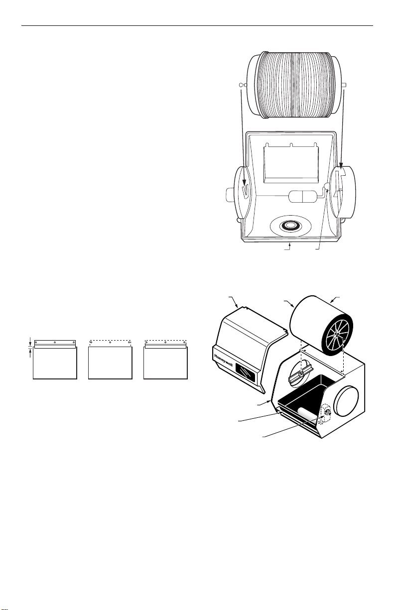
COVER
BEARING END OF
DRUM SHAFT
FLOAT
VALVE
M20221
DRUM
ASSEMBLY
Fig. 3. Mounting HE160 on plenum.
Hang the basin from the mounting hanger and
16.
secure with the sheet metal screws provided.
Insert the screws into the pilot holes and through to
17.
the back of the bracket.
Snap the motor plate and inlet into the basin. Be
18.
sure the tabs fit into the corresponding basin slots.
Install the drain and cap at the bottom of the basin,
19.
with the cap on the outside of the humidifier housing. Hand-tighten until the drain does not turn; do
not overtighten.
M20220
HUMIDIFIER HOUSING
WATER PAN
WATER VALVE OPENING
Fig. 5. Disassembling drum humidifier
Install the float into the slot in the side of the basin.
1.
Hand-tighten the nut.
NOTE: For HE120, attach the float on the same side as
the motor; install the plug in the opposite slot.
Shut off the water. (Either hot or cold water and
2.
either hard or softened water can be used in the
humidifier.)
3 69-1571
M12252
 Loading...