

Page 1
HE120A,B
68-0190-3
By-Pass Drum Humidifier
PRODUCT DATA
FEATURES/BENEFITS
• Can be installed in a furnace room without a drain.
• Capable of humidifying a large area.
• Small footprint, light weight and reversible
components allow easy mounting on either warm air
supply or return air duct of any forced air furnace.
• Minimal amount of water and electricity needed for
operation, saving the homeowner money.
• Unique snap-lock fittings and reversible components
allow quick installation and maintenance.
• Interior components designed for easy clean up
or replacement.
APPLICATION
The HE120A,B By-Pass Drum Humidifier uses the warm air
furnace blower to provide humidification for the whole house.
The HE120A,B works with virtually any Honeywell humidity
control, but use the Honeywell Perfect Climate Comfort
Center™ control for optimal performance.
• Durable thermoplastic cabinet resists rust, corrosion
and warpage.
• Includes easy-to-use humidity control that mounts on
the wall or duct for more installation flexibility.
•Perfect Climate Comfort Center™ control can be
installed to replace both the thermostat and humidity
control for improved aesthetics and convenience.
• Optional Automatic Flushing Timer can be used to
reduce the frequency of maintenance. A drain is
required if the timer is installed.
Contents
Application........................................................................... 1
Features/Benefits ................................................................ 1
Specifications ...................................................................... 2
Ordering Information ........................................................... 2
Installation ........................................................................... 3
Wiring .................................................................................. 4
Operating the Humidifier ..................................................... 4
Operation ............................................................................ 5
Maintenance........................................................................ 5
Checkout Procedure ........................................................... 6
Troubleshooting ................................................................... 6
Replacement Parts.............................................................. 7
® U.S. Registered Trademark
Copyright © 1998 Honeywell Inc. • All Rights Reserved
Page 2

HE120A,B BY-PASS DRUM HUMIDIFIER
SPECIFICATIONS
Capacity:
At 120°F (49°C) plenum temperature and 0.20 static pressure
drop across supply and return:
17 gallons per day (gpd) or 64 liters per day (lpd).
Humidified Area:
For precise sizing and product selection, use Honeywell’s
HumidiCalc™ humidifier sizing software. If unavailable, refer to
Ta b le 1.
Table 1. Size Of Area That Can Be Humidified.
House Air Changes
Description Per Hour
Loose Two 1,845 171
Average One 2,575 239
Tight One-half 4,045 376
Drum Motor:
24 Vac, 3W, 1 rpm, bi-directional.
Plenum Opening Dimensions (Height x Width):
6-5/8 in. x 8-1/2 in. (168 mm x 216 mm).
Area (up to)
Sq ft Sq m
HE120 B Tradeline® By-Pass Drum Humidifier package
includes:
mounting template and hardware,
self-piercing saddle valve,
24 Vac transformer and wire,
by-pass tubing,
summer shut-off damper,
H1008A Automatic Humidity Control with HumidiCalc+™
Software.
10-7/8 (276)
11-11/16 (297)
12-3/8 (314)
1
0
-1
5
/1
(2
6
7
8
)
By-Pass Duct Opening (Diameter):
6 in. (152 mm).
M12254A
Dimensions:
Refer to Fig. 1.
Testing Standard:
Air Conditioning and Refrigeration Institute: Standard 610.
Models:
HE120A Tradeline® By-Pass Drum Humidifier package
includes:
mounting template and hardware,
self-piercing saddle valve,
24 Vac transformer and wire,
by-pass tubing,
summer shut-off damper,
Accessories:
Fig. 1. HE120A,B Dimensions in in. (mm).
C7089H Outdoor Temperature Suensor.
H1008A Automatic Humidity Control with HumidiCalc+™
Software (software calculates dewpoint to prevent
moisture condensation).
H908A Convertible Humidity Control.
HC40 Automatic Humidifier Flushing Timer.
HumidiCalc™ Humidifier Sizing Software (software
calculates required humidifier capacity for application).
PC8900 Perfect Climate Comfort Center™ Control.
H908A Convertible Humidity Control.
ORDERING INFORMATION
When purchasing replacement and modernization products from your TRADELINE® wholesaler or distributor, refer to the
TRADELINE® Catalog or price sheets for complete ordering number.
If you have additional questions, need further information, or would like to comment on our products or services, please write or
phone:
1. Your local Home and Building Control Sales Office (check white pages of your phone directory).
2. Home and Building Control Customer Logistics
Honeywell Inc., 1985 Douglas Drive North
Minneapolis, Minnesota 55422-4386
In Canada—Honeywell Limited/Honeywell Limitée, 35 Dynamic Drive, Scarborough, Ontario M1V 4Z9.
International Sales and Service Offices in all principal cities of the world. Manufacturing in Australia, Canada, Finland, France,
Germany, Japan, Mexico, Netherlands, Spain, Taiwan, United Kingdom, U.S.A.
68-0190–3
2
Page 3
HE120A,B BY-PASS DRUM HUMIDIFIER
INSTALLATION
WARNING
Electrocution and Chemical Hazard.
Can cause death or blindness.
Do not cut or drill into any air conditioning line or
electrical accessory.
CAUTION
Freezing Water Hazard.
Can result in water damage to property.
Locate the humidifier where the ambient temperature is
between 32°F and 180°F (0°C and 82°C).
IMPORTANT
To assure optimal product performance, be sure the
template is level before marking location.
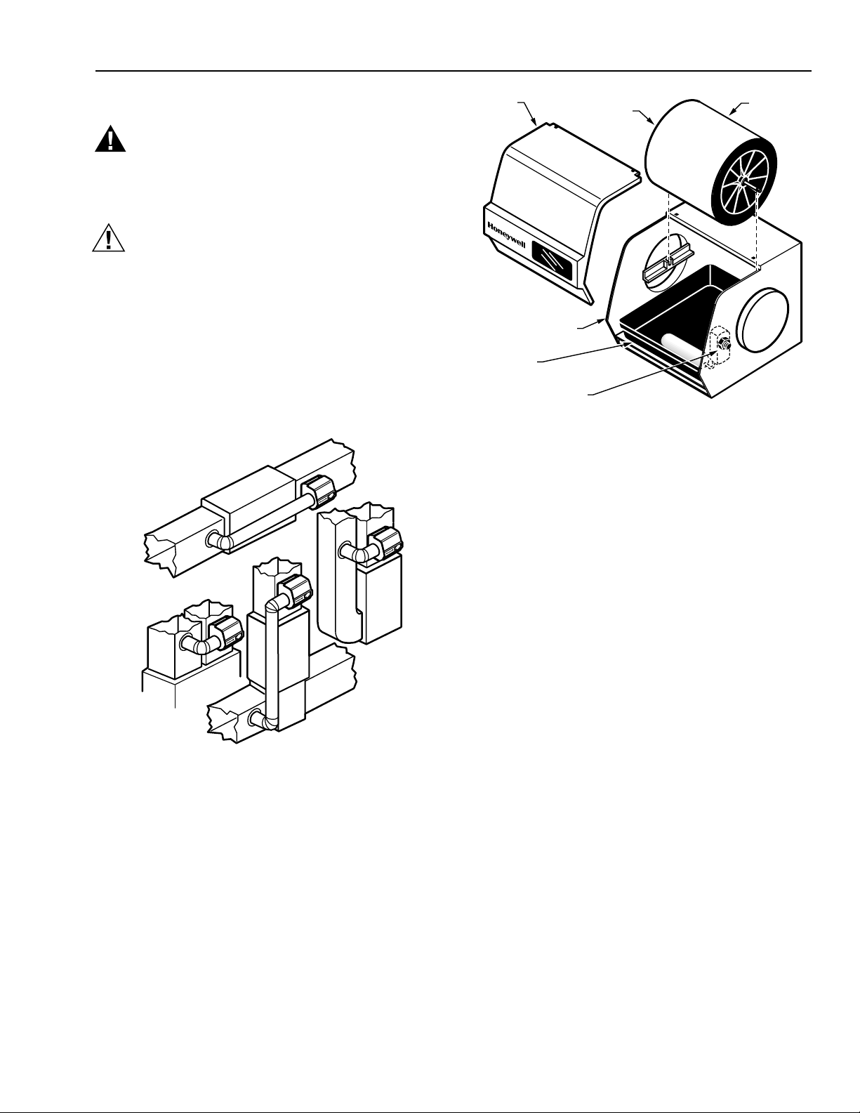
1. Determine the best location for the humidifier and draw a
level line on the duct. See Fig. 2 for humidifier
components.
HORIZONTAL
COVER
HUMIDIFIER HOUSING
WATER PAN
WATER VALVE OPENING
BEARING END OF
DRUM SHAFT
DRUM
ASSEMBLY
M12252
Fig. 3. Humidifier components.
9. On the inside of the humidifier housing where the by-
pass tube connects, snap the bearing bracket into place
with the U shape of the bracket pointing up.
10. Snap the motor plate into place on the opposite side of
the humidifier housing.
HIGHBOY
DOWN
FLO
BOY
LOW
M13170
Fig. 2. Typical humidifier installation locations.
2. Tape the template in position and trace around it.
3. Remove the template and carefully cut the rectangular
opening.
4. Position the humidifier housing (See Fig. 3.) over the hole
(be sure it is level) and mark the five mounting holes.
5. Set the cabinet aside and drill the five 7/64 in. (3 mm)
mounting holes.
6. Start the three 3/4 in. (19 mm) sheet metal screws in the
top holes.
7. Place the humidifier housing over the screws, level the
housing and tighten the three screws.
8. Use two 1/2 in. (13 mm) screws to secure the humidifier
housing at the bottom.
NOTE: Be sure the motor coupling is positioned toward
the top.
11. Place the lead wires through the hole in the bottom of the
motor cover and snap the cover in place.
12. Cut an opening for the 6 in. (152 mm) collar in the
selected by-pass location.
NOTE: Be sure to install a duct damper for summer
shutoff if there is air conditioning.
13. Install the 6 in. (152 mm) collar.
14. Use sheet metal screws to connect the by-pass tubing
from the collar to the humidifier.
15. Seal the connections with duct tape.
16. Insert the drain fitting in the bottom of the humidifier
housing.
NOTE: Be sure the overflow tube is positioned toward
the front and on the same side as the
by-pass tubing.
17. Place the water pan in the humidifier housing so the
overflow tube is above the previously installed
drain fitting.
NOTE: Be sure the tubing does not touch hot surfaces
and sharp edges.
18. Attach a 3/8 in. (10 mm) ID tubing to the drain fitting and
route downward to a suitable drain or catch basin.
19. Screw the float onto the float valve assembly.
3
68-0190–3
Page 4

HE120A,B BY-PASS DRUM HUMIDIFIER
20. Attach the float valve to the humidifier housing on the
same side as the motor.
21. Insert the valve hole plug in the double D hole on the
opposite side of the valve.
22. Assemble the drum and humidifier pad. See Fig. 4.
SQUEEZE
OPEN
DRUM END
PAD
TINNERMAN
DRUM SHAFT
METAL TABS
CLOSED DRUM END
SLIGHTLY
TO INSTALL
M12243
Fig. 4. Assembling drum and humidifier pad.
23. Insert the drum assembly into the motor coupling end
and snap into the bearing end.
24. Install the saddle valve (using the instructions on the
saddle valve bag) on the nearest cold water pipe.
25. Connect the copper tubing and route to the humidifier.
26. Connect the copper tubing to the humidifier valve and
finger tighten.
27. Use a wrench to turn the nut one and one-half turns
more.
28. Tu rn the water on at the saddle valve and adjust the
water level to 1-3/8 in. deep.
NOTE: Turn the valve adjustment screw (located on the
water valve inside the humidifier) clockwise to
lower and counterclockwise to raise.
WIRING
CAUTION
Electrical Shock Hazard.
Can shock or burn out equipment.
• Disconnect power supply before installing or
servicing.
•To prevent premature transformer burnout on
multispeed blower applications, do not wire the high
voltage side of the transformer to the same power
source that services the furnace blower.
All wiring must comply with applicable local codes, ordinances
and regulations.
1. Mount the transformer in a convenient location.
2. Connect the wires to the 120V side of the transformer.
3. Wire the drum motor, transformer and humidity control.
Refer to the humidity control installation instructions for
mounting and wiring information.
OPERATING THE
HUMIDIFIER
The HE120A humidifier is
controlled by the H908A
Humidity Control that is
installed either on an interior
wall in the living area or on the
return air duct. Choose the
setting using the combination
relative humidity/outdoor
temperature setting scale on your humidity control. Match the
dial setting to the outdoor temperature for optimizing the
humidity level while reducing the moisture condensation on
your windows. Table 2 can also be used to adjust the humidity
control to the recommended setting.
H908A
M13155
Table 2. Recommended Humidity Control Settings.
At Outside Temperature Recommended Setting At Outside Temperature Recommended Setting
-20°F (-29°C) 15 +10°F (-12°C) 30
-10°F (-23°C) 20 +20°F (-7°C) 35
0°F (-18°C) 25 Above 20°F (-7°C) 40
NOTE: As the outside temperature drops, the recommended setting is lowered to accommodate the effects of dewpoint. These
settings should reduce the accumulation of moisture and ice on the windows and in other areas of the house.
Some indoor activities such as cooking, showering and clothes
drying can cause excessive levels of humidity and start the
accumulation of moisture on the windows.
Your Honeywell HE120B
Humidifier is controlled by the
Honeywell H1008 Automatic
Humidity Control with
NOTE: If this condition persists for more than a few hours, set
the humidity control to the lowest setting to turn off the
humidifier. If the condition does not improve, ventilate
your home to remove the moisture.
HumidiCalc+ Software. The
automatic humidity control is
mounted in the return air duct
where it can be exposed to the air
stream of the return air. The
HumidiCalc+ Software inside
your automatic humidity control is
68-0190–3
designed to automatically adjust
4
H1008A
M12817
Page 5

HE120A,B BY-PASS DRUM HUMIDIFIER
M12252
WATER PAN
HUMIDIFIER HOUSING
DRUM
ASSEMBLY
BEARING END OF
DRUM SHAFT
COVER
WATER VALVE OPENING
the humidity level based on indoor temperature and humidity,
inferred or measured outdoor temperature, and the setting of
the frost factor dial. The frost factor allows for variations in
furnace size, window insulation and average daily climate
temperature.
The Automatic Humidity Control with HumidiCalc+ Software
requires an initial adjustment period. Set the frost factor dial on
5 and use Table 3 to adjust the frost factor—only one setting at
a time—increasing the dial setting if you feel you need more
humidity, or reducing the setting if you see moisture on the
inside of your windows. For more precise humidity adjustment,
set the frost factor between dial settings. Allow two days for the
humidity level to subside before making further adjustments.
Once you have tuned in the proper setting, you should never
have to adjust it again. HumidiCalc+ Software takes over and
makes any future adjustments caused by varying outdoor
temperatures, thus reducing moisture build-up on windows
while maintaining the optimal humidity level.
Table 3. Recommended Frost Factor Settings.
Humidity Level Recommended Adjustment
Insufficient humidity Increase the frost factor dial by one
Condensation on
windows
setting
Decrease the frost factor dial by one
setting
Every 1 to 3 Months
(Depending on Water Quality)
CAUTION
Voltage Hazard.
Can cause electrical shock and equipment damage.
Disconnect power supply before installing or servicing.
IMPORTANT
Never oil any part of the humidifier.
Use the following procedure to clean the humidifier:
1. Disconnect the power and turn off the humidifier water
supply.
2. Remove the humidifier cover by lifting up the bottom of
the cover. See Fig. 5.
OPERATION
The HE120A,B humidifier uses the principle that vapor
(evaporated water) is created when warm air blows over a
water soaked area. As the vapor circulates, the relative humidity
rises.
The humidity control monitors the relative humidity and
activates the humidifier accordingly. The humidifier has a water
supply that disburses water over a humidifier pad. The warm
dry air from the furnace passes over the humidifier pad and
picks up the moist air to circulate it through the house.
Humidified air feels warmer and more comfortable so the
homeowner may be able to lower the thermostat heating
setpoint and save money on heating fuel bills. The end result is
that the humidifier gives the homeowner a comfortable
environment that is also energy efficient.
MAINTENANCE
A regular maintenance program prolongs the life of the
humidifier and provides a more comfortable environment.
Frequency of cleaning depends on the condition of the water.
You can use either hard or soft water in the humidifier, but
hard water mineral deposits are more difficult to clean than
soft water deposits.
Fig. 5. Location of humidifier parts.
3. Lift up the drum shaft from the bearing end and slide it
out of the motor coupling to remove the drum assembly.
NOTE: You will encounter some resistance and hear an
audible click when removing the drum shaft.
4. Remove the drum from the assembly.
5. Grasp the rubber valve seat between thumb and
forefinger and lift it upward to remove the valve seat from
the valve. (The seat is located inside the humidifier
housing at the water valve opening.)
6. Raise up the float and remove the water pan.
7. Refer to Fig. 6 to disassemble the drum.
8. Clean all humidifier parts in a 50 percent solution of
vinegar (or a humidifier cleaner) and water. Soak
overnight to remove stubborn deposits.
NOTE: Replace humidifier pad yearly. The actual
frequency depends on the quality of the water
used.
5
68-0190–3
Page 6

HE120A,B BY-PASS DRUM HUMIDIFIER
9. After the humidifier components are clean, reassemble
the humidifier by reversing the order of steps 1 through 7.
NOTE: To be sure that the drum shaft is completely
seated, listen for the click.
10. Verify the humidifier operation by following the steps in
the Checkout Procedure section.
End of Humidification Season
The humidifier should be cleaned and shut off at the end of the
heating season. Use the Every 1 to 3 Months section, steps 1
through 9, to shut down for the season.
IMPORTANT
Be sure the humidifier power is off and the humidifier
is empty.
Vacation
When you leave on vacation, turn off the humidifier water
supply and your humidity control. When you return, turn on the
humidifier water supply and reset your humidity control.
CHECKOUT PROCEDURE
After winter startup or maintenance, use the following
procedure to check the humidifier operation:
1. Tu rn on the humidifier power and water supply.
2. Check the water level in the humidifier water pan; water
level setting should be 1-3/8 in. deep. Turn the valve
adjustment screw (located on the water valve inside the
humidifier) clockwise to lower the water level and
counterclockwise to raise it.
3. Tu rn the H908A Convertible Humidity Control to the
highest setting or the H1008A Automatic Humidity
Control to the Test position, and set the thermostat to
10°F (6°C) above the room temperature.
NOTE: The H1008A Automatic Humidity Control stays
in the test mode for thirty minutes. After thirty
minutes, the control automatically resets to the
maximum frost factor setting. If system
checkout has not been completed in thirty
minutes, the test mode can be extended by
turning the dial back to one of the dial settings
and then returning it to the test mode.
4. Check that the humidifier pad is rotating.
5. Reset the thermostat and the Convertible Humidity
Control to a comfortable setting, or the Automatic
Humidity Control to the desired frost factor setting, for
automatic operation.
OPEN
DRUM END
PAD
TINNERMAN
DRUM SHAFT
METAL TABS
CLOSED DRUM END
SQUEEZE
SLIGHTLY
TO INSTALL
M12243
Fig. 6. Drum assembly parts.
TROUBLESHOOTING
Refer to Table 4 for troubleshooting procedures.
Table 4. Troubleshooting Procedures.
Problem What To Look For What To Do
Low humidity Furnace blower not
operating.
Rapid air changes.
Drafts (cold air is dry and
is an added load to the
humidifier).
High humidity Condensation on walls. • Turn off humidity control and water until condensation is completely
Heavy condensation on
windows.
• Reset circuit breaker or check for blown fuse.
• Check that the furnace power is on.
• Check all external wiring connections.
• Check the humidity control setting.
• Call a professional heating contractor.
• Keep doors and windows closed.
• Close fireplace damper when not in use.
• Keep exhaust fan running time to a minimum.
• Seal around doors and windows.
evaporated.
• Turn humidity control down low enough to eliminate condensation caused by
moisture from bathing, mopping, cooking, etc. If moisture persists, more
ventilation is needed.
68-0190–3
6
Page 7

REPLACEMENT PARTS
Refer to Fig. 7 and Table 5 when ordering replacement parts.
HE120A,B BY-PASS DRUM HUMIDIFIER
8
10
9
14
9
13
12
11
3
1
9
9
4
5
7
6
Fig. 7. Exploded view of humidifier parts.
7
2
M12239A
68-0190–3
Page 8

HE120A,B BY-PASS DRUM HUMIDIFIER
Table 5. List Of Replacement Parts For HE120 Humidifier.
Exploded View Number Description HE120 Part Number
1 Cover Assembly 32000131-001
2 24 Vac motor 32000132-001
3 Humidifier housing 32000133-001
4 Water pan 32000134-001
5 Float for valve 32000135-001
6 Float valve 32000136-001
7 Valve seat 32000137-001
8 Saddle valve assembly 32001616-001
9 Drum assembly 32000141-001
10 Humidifier pad (includes clips) 32000146-001
11 Transformer (10 VA) 32001652-001
12 Bearing bracket 32000147-001
13 Convertible Humidity Control H908A1003
14 Automatic Humidity Control H1008A1008
— Current Sensing Relay 32001754-001
Home and Building Control
Honeywell Inc.
Honeywell Plaza
P.O. Box 524
Minneapolis MN 55408-0524
Honeywell Latin American Region
480 Sawgrass Corporate Parkway
Suite 200
Sunrise FL 33325
68-0190—3 J.S. Rev. 6-98
68-0190–3
Home and Building Control
Honeywell Limited-Honeywell Limitée
155 Gordon Baker Road
North York, Ontario
M2H 3N7
Honeywell Europe S.A.
3 Avenue du Bourget
1140 Brussels
Belgium
Printed in U.S.A. on recycled
paper containing at least 10%
post-consumer paper fibers.
8
Honeywell Asia Pacific Inc.
Room 3213-3225
Sun Hung Kai Centre
No. 30 Harbour Road
Wanchai
Hong Kong
www.honeywell.com/yourhome
 Loading...