

Page 1

Storey
Controller
HCE 40
Installation and Operation
Page 2

Page 3

Contents
Contents
Overview 3
Application 3
Installation procedure 4
Creating zoning plan 4
Installing 4
Configuring and making electrical connections 4
Start-up 4
Creating zoning plan 5
Determining temperature zones 5
Filling out zoning plan 6
Installation 10
Wall installation 11
Installation on DIN rails 12
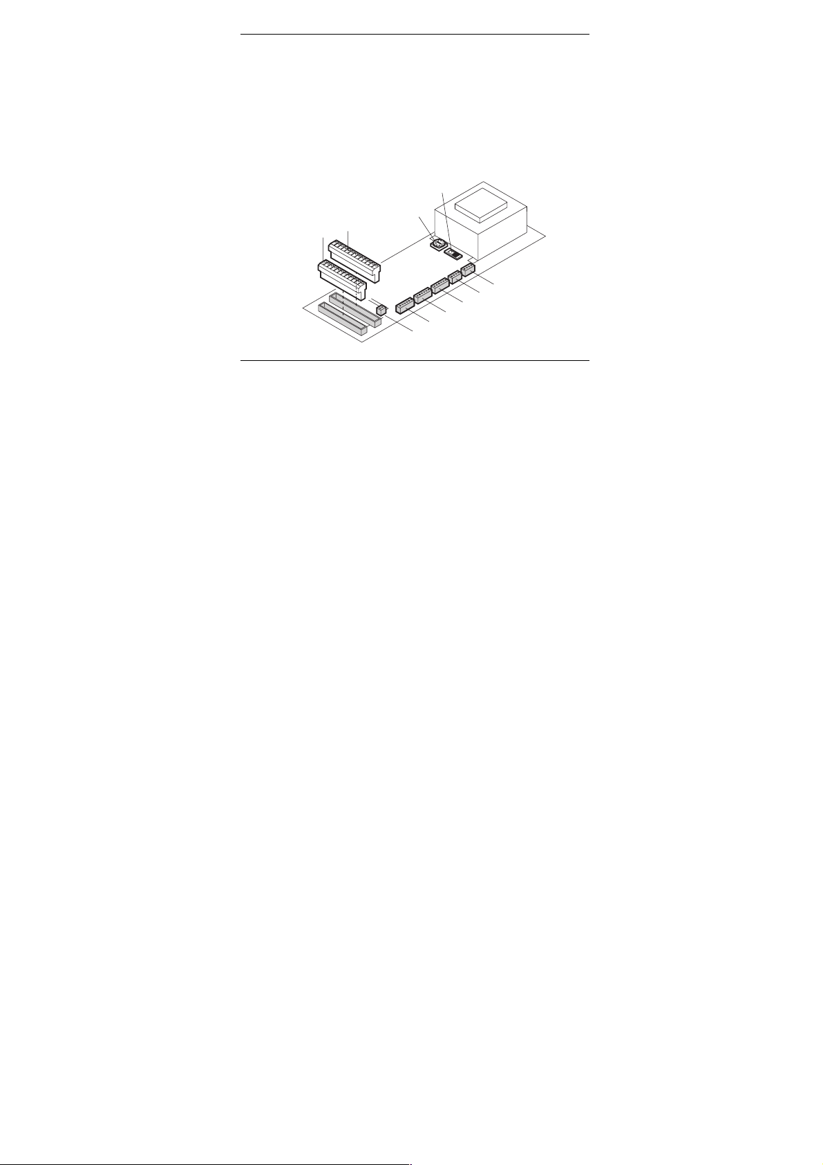
Installing storey controller components 12
Description 13
Layout of circuit board 13
LED indicators on storey controller 14
Operating modes of storey controller 15
Buttons on storey controller 17
Configuration and electrical connection 19
Opening housing 19
Branching out time programs 20
1
Page 4

Contents
Setting actuator 22
Switching between heating/cooling 23
Cabling connections 24
Start-up 35
Starting up storey controller 35
Start-up with central operating device 36
Assigning setpoint adjusters of type HCU 23 or HCW 23
to a zone 40
Removing assignment 40
Saving settings at central operating device 43
Checking installation 43
Completing start-up 44
Resetting storey controller to state of delivery 45
Appendix 46
Glossary 46
Help with problems 47
Overview of heating components 50
Zoning plan 51
2
Page 5

Overview
Overview
For your information
Technical terms are explained in the glossary (Page 46). They are
identified in the text by an *.
Application
The storey controller HCE 40 receives information on the temperature
of the room from the setpoint adjusters*, room temperature sensors of
type RF 20 or from the central operating device* HCM 100. The storey
controller uses this information to control the boiler feedback*, the
pump relay and the thermal actuators* (see "Overview of heating
components" Page 50).
The storey controller HCE 40 is hard-wired to setpoint adjusters of
type HCU 23 or HCW 23, room temperature sensors of type RF 20 or
the central operating device HCM 100.
It has a self-learning controller (fuzzy logic), which automatically
adjusts the control parameter according the installation conditions.
The desired room temperature is reached quickly and then
maintained.
3
Page 6

Overview
Installation procedure
Creating zoning plan
• Determining which heating circuits* are controlled by the storey
controller.
Installing
• Installing the components of the storey controller HCE 40.
Configuring and making electrical connections
• Setting the storey controller to the actuator type, attaching cables to
the respective connections and connect components together.
Start-up
• Assigning room names to the temperature-zones with the central
operating device HCM 100 if applicable.
4
Page 7

Creating zoning plan
Creating zoning plan
A temperature zone is an area of the building, e.g. a room, in which
the setpoint temperature* is set with a setpoint adjuster. The storey
controller controls all thermal actuators of a temperature zone
identically.
5 temperature zones can be set up for each storey controller.
3 actuators can be connected in each of 3 zones, and 2 actuators can
be connected in each of the remaining 2 zones.
The total number of actuators which can be controlled by a signal
storey controller is limited to 10.
Determining temperature zones
Damage caused by equipment from other manufacturers!
Caution!
► Group actuators (by type and location) which are controlled with the
storey controller.
► Group together all actuators which are controlled by a setpoint
adjuster in a temperature zone.
5
The storey controller was designed for use with
components from Honeywell only!
► Use only H 200 AG (normally closed) or H 200 AO
(normally open)-type actuators.
Page 8

Creating zoning plan
If more than 5 temperature zones or 10 actuators are present:
► Determine the number of additional storey controllers required using
the following table:
Temperature
zones (maximum)
Actuators
(maximum)
No. of storey
controller
5 10 1
10 20 2
15 30 3
Hint: The example at the end of this section shows zone divisions with
corresponding zoning plan.
Filling out zoning plan
► Copy the sample zoning plan ("Zoning plan" Page 51) (archive it).
► Enter the type and installation location of the respective actuator in
each temperature zone.
► Assign a setpoint adjuster or room temperature sensor to each
temperature zone.
► Assign room names if necessary.
► Hand over the zoning plan to the customer after installation.
6
Page 9
Creating zoning plan
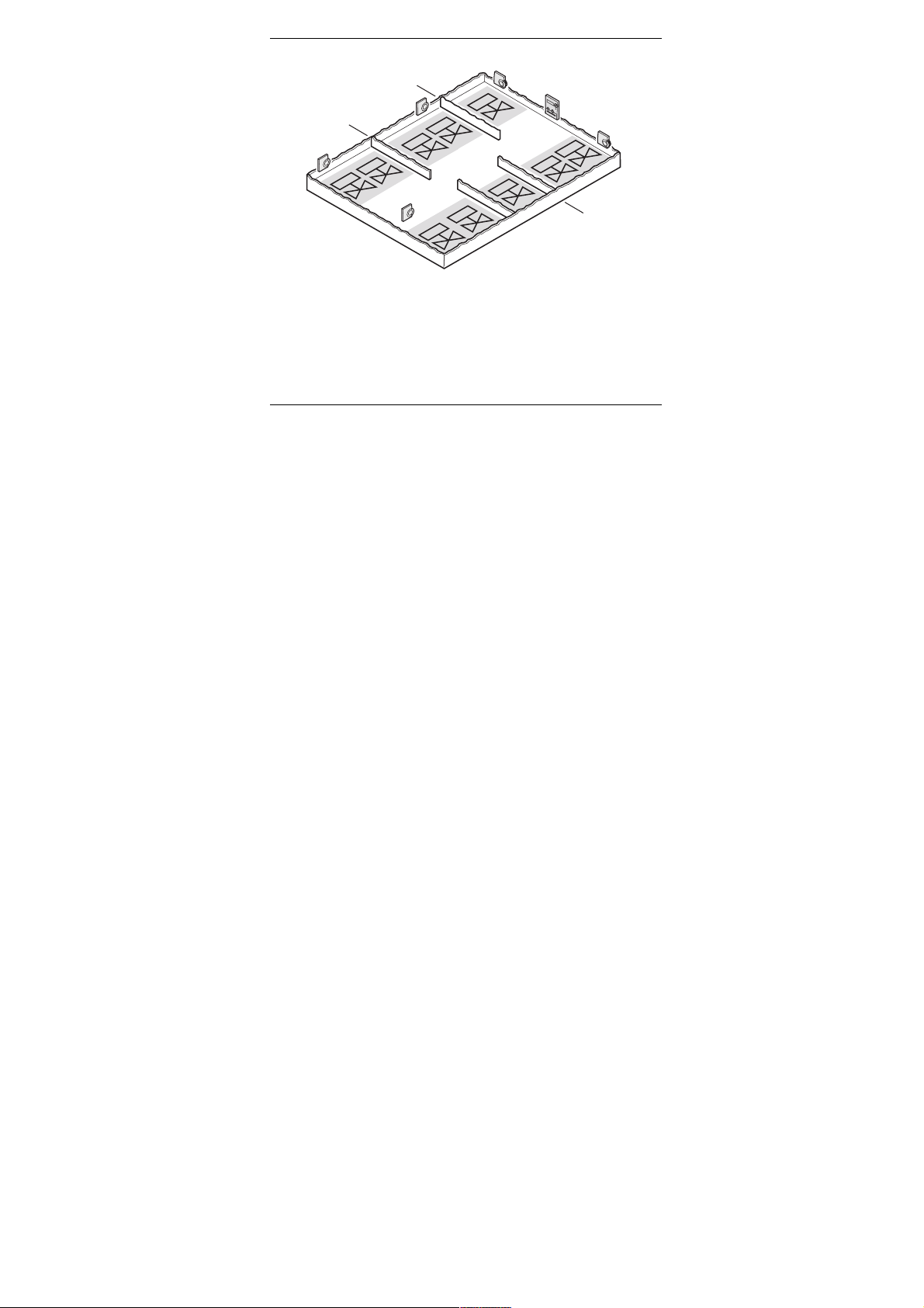
Example of zone divisions
Zone 5
Zone 1
Zone 2
Dining
Living
Bathroom
WC
Kitchen
Bedroom
Hall
Zone 4
Zone 3
This example shows:
• A home divided into five temperature zones.
• Bathroom and WC are controlled by one setpoint adjuster. One
temperature zone is sufficient for three actuators.
• The maximum number of actuators (10 per storey controller) is used
to the full with the storey controller.
7
Page 10
Creating zoning plan
The example yields the following zoning plan:
Temperature zone
Zone 1
Actuator
(type, location)
Heating loop 1
(living room)
Heating loop 2
Setpoint
adjuster
(location)
Room name
at operating
device
Living room "Living"
(living room)
Zone 2
Heating loop 1 (dining
room)
Heating loop 2 (dining
Dining room "Dining"
room)
Zone 3
Heating loop 1 (bathroom) "Bathroom/
Heating loop 2 (bathroom)
Heating loop 3 (WC)
Bathroom and
WC
WC"
Heating loop 1 (bedroom) Bedroom "Bedroom"
Zone 4
Heating loop 2 (bedroom)
Zone 5 Heating loop 1 (kitchen) Kitchen "Kitchen"
8
Page 11

Creating zoning plan
9
Page 12

Installation
Installation
The storey controller is sensitive to excessive
temperatures!
Caution!
► When selecting the location for operation, ensure
that the ambient temperature in that area does not
The storey controller was designed for installation in a distributor box.
exceed 50 °C.
If insufficient space is available there, select a location free of humidity
and moisture.
The storey controller can be installed in one of two ways:
• on the wall
• on DIN rails
Note the 82 mm installation height of the storey controller!
If the storey controller is installed at a severe angle, the
transformer must be on top to allow for better ventilation.
10
Page 13
Installation
Wall installation
Four 4.2-mm holes for installation are located on the storey controller.
Dimensions of storey controller in mm
ø4.2
50
82
65
82
324
335
► Mark, drill and insert plugs into fastening holes.
► Screw on the storey controller.
11
Page 14
Installation
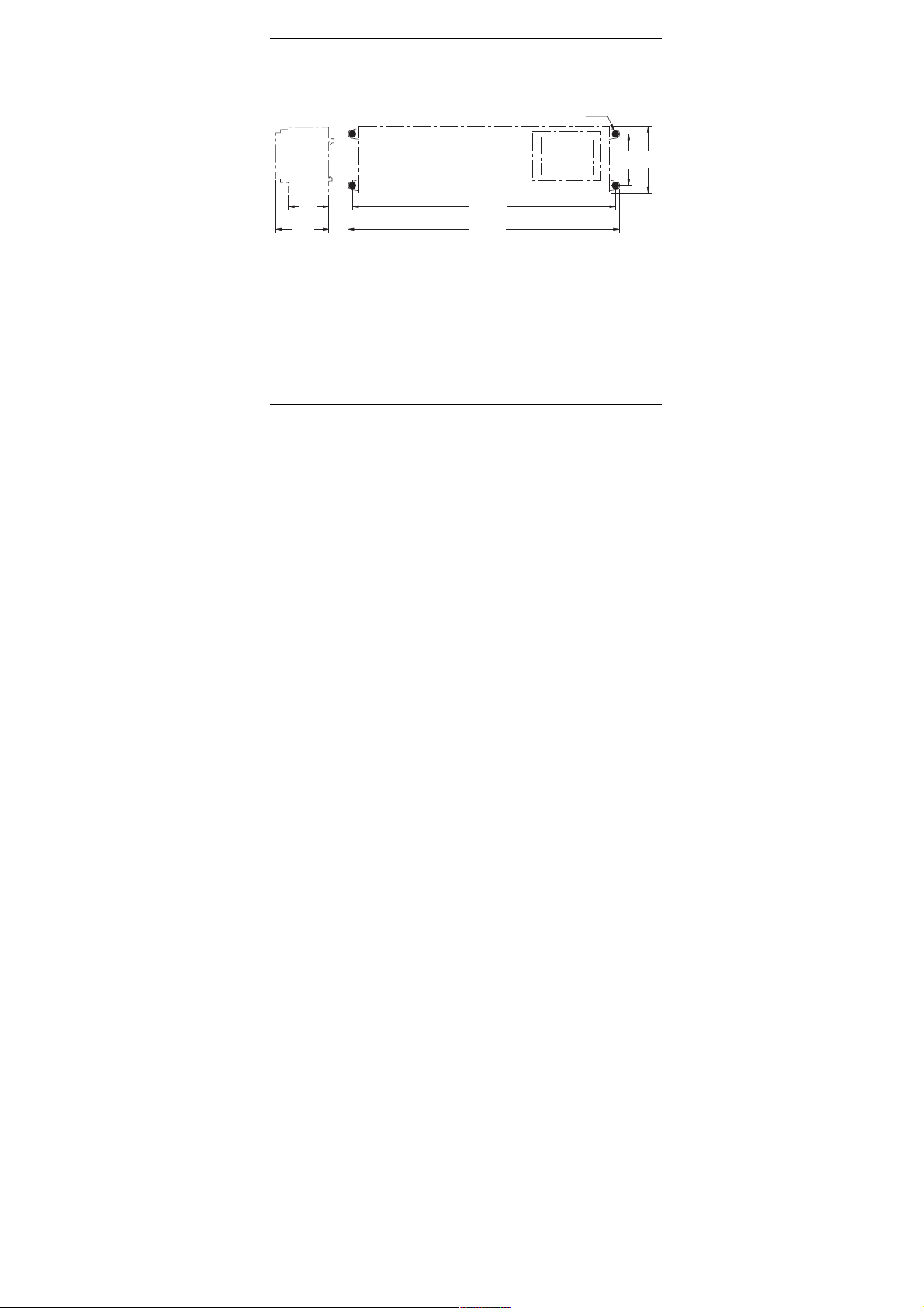
Installation on DIN rails
► Place housing on the
DIN rail from below (1).
► Press upper edge of
housing toward the
wall until it snaps into
place (2).
Á
À
Installing storey controller components
► Install components as described in the accompanying installation
instructions.
12
Page 15
Description
Description
Layout of circuit board
1. Connector (1 to 12)
2. Connector (13 to 25)
3. Switch used to branch out
temperature zones (Page 20)
4. Switch used to configure the
actuators (Page 22)
5. Connection for temperature zone 5
6. Connection for temperature zone 4
7. Connection for temperature zone 3
8. Connection for temperature zone 2
9. Connection for temperature zone 1
10. Plug-in terminal for connection of a
potential-free heating/cooling
contact (Page 23)
Ã
Â
Á
À
13
14
15
16
17
18
19
20
21
1
22
2
23
3
24
4
25
5
6
7
8
9
10
11
12
13
É
È
0
Ç
C
Ä
Å
Æ
Page 16
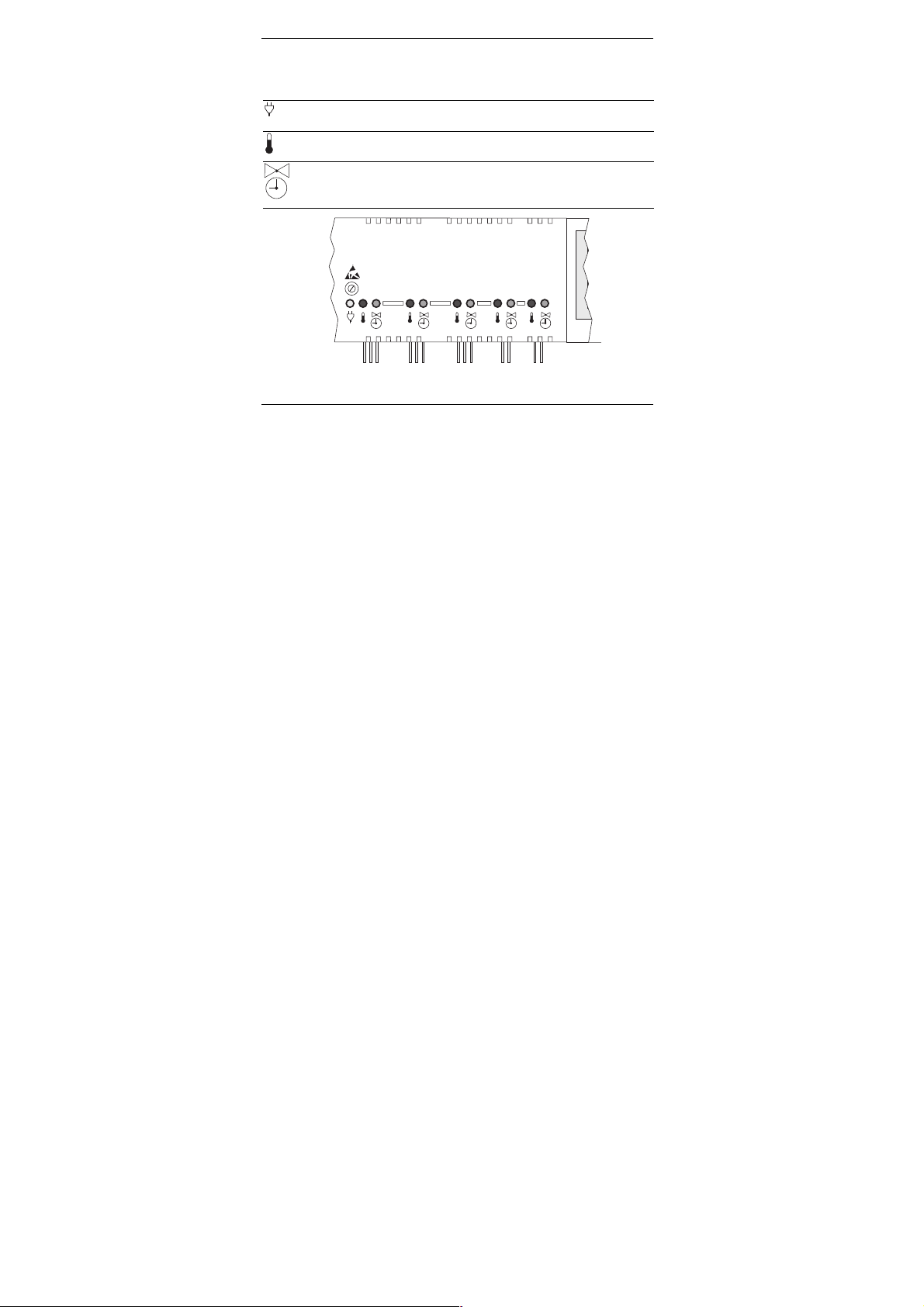
Description
LED indicators on storey controller
The LEDs on the storey controller indicate the operating mode of the
storey controller and the installed temperature zones.
(green)
(red)
(green)
Normal mode /
Power-on indicator
Connected setpoint adjuster /
Fault indication: wire break or short circuit
Position of the actuators /
Assignment of temperature zones /
Fault indication: Faulty communication with HCM 100
14
Zone 1 Zone 2 Zone 3 Zone 4 Zone 5
Page 17
Description
Operating modes of storey controller
Normal mode
In normal mode the green LEDs
position of the actuators:
(green)
(red)
Illuminating Mains voltage connected
Off Mains voltage not connected
Flashing Room sensor or setpoint adjuster
provide information on the
connection faulty.
Illuminating Thermal actuator opened
Flashing Faulty communication with HCM 100
(green)
Off Thermal actuator closed
The setpoint adjusters HCW 23 or HCU 23 are clearly assigned via
the wiring of the temperature zones. The respective red LEDs do not
illuminate. If the red LED flashes anyway, the connection to the
setpoint adjuster has been interrupted, short circuited or an incorrect
resistance value was detected.
15
Page 18

Description
Installation mode
• In installation mode, temperature zones are assigned to the central
operating device.
Refer to Section "Start-up with central operating device" on
Page 36.
Device display (configuration button 1)
• The device display informs you of the configuration of your storey
controller system, i.e. the assignment of setpoint adjusters to the
temperature zones of room names at the central operating device.
Refer to Section "Checking installation" on Page 43.
16
Page 19

Description
Buttons on storey controller
• Configuration button (1):
Display of the assignment of
temperature zones to the central
operating device.
Selection of the temperature zone
which is to be assigned to the
central operating device or a
setpoint adjuster (see Button
check
installation
functions on Page 18).
• Delete button (2):
Removing the temperature zone
Button 2
Button 1
from the central operating device
or a setpoint adjuster (see Button
functions on Page 18).
17
Page 20

Description
Button functions
► Press the configuration
button (1) briefly.
The assignment of the storey
controller to the central operating
device, setpoint adjusters and room
temperature sensors is displayed.
The storey controller shows up in the
device display.
► Press the configuration
button (1) briefly once
more.
► Press the delete
button (2).
18
The green LED
illuminates if a
temperature zone is assigned to the
central operating device.
The red LED
illuminates if an RF
20, HCU 23 or HCW 23 is connected.
The display returns to normal mode
after 60 seconds.
The red LED
of temperature zone 1
flashes.
Installation mode is active.
The selected temperature zone is
removed (the LED flashes).
Page 21

Configuration and electrical connection
Configuration and electrical connection
► Unplug the power plug before opening the housing.
Damage to exposed components!
Caution!
Opening housing
► Loosen the screw on the
front (1).
► Push both snap locks
inward (2).
► Remove the housing cover
from above (3).
19
The electronic components of the storey controller can
be damaged by static electricity discharge!
► Do not touch such components.
► Touch an earthed piece of metal to discharge static
electricity from your body.
Á
À
Â
Á
Page 22

Configuration and electrical connection
Branching out time programs
You can use the setpoint and temperature input* of zone one
as source for other zones. The branching is be done by the
selector switch (1).
1. Switch used to assign temperature zones to setpoint
and temperature inputs.
À
► Set the switch according to the following table.
20
Page 23

Configuration and electrical connection
Switch
position
Property
A setpoint and temperature input is assigned to each
temperature zone.
The setpoint and temperature input of temperature
zone 1 is also valid for temperature zone 2.
The setpoint and temperature input of temperature
zone 1 is also valid for temperature zones 2 and 3.
The setpoint and temperature input of temperature
zone 1 is also valid for temperature zones 2, 3 and 4.
The setpoint and temperature input of temperature
zone 1 is also valid for temperature zones 2, 3, 4 and
5.
If a room temperature sensor is not connected to a branched
out temperature zone, the actual value of temperature zone 1
is used for this area.
21
Page 24

Configuration and electrical connection
Setting actuator
Only one type of actuator can be connected to a storey
controller at a time. If actuators which are open with current
and actuators which are closed with current are to be used,
two storey controllers with the respective suitable controller
are required.
1. Switch used to configure
the actuators
(O = Open, C = Closed)
À
► Check the type of actuator being used.
22
Page 25

Configuration and electrical connection
► Set the switch according to the following table.
Switch
Actuator type Property
position
Normally closed
H 200 AG
Normally open
H 200 AO
Opens the heating circuit
when the actuator is
supplied with current.
Opens the heating circuit
when the actuator is not
supplied with current.
Switching between heating/cooling
You can switch between the cooling and heating functions of the
storey controller.
1. Terminal for the connection of a
potential-free switch.
Switches between heating/cooling
(open = heating, closed = cooling)
► Set the potential-free switch in accordance with the desired function.
23
3
1
4
1
5
1
6
1
7
1
8
1
9
1
0
2
1
2
2
2
1
3
2
2
4
2
5
3
2
4
5
6
7
8
9
0
1
1
1
2
1
À
Page 26

Configuration and electrical connection
Cabling connections
Permissible cable types and lengths
Cable (designation) Connection: Storey
controller HCE 40 and -
JE-Y(St)Y 2×2×0.8
Central operating device
HCE 100
Setpoint adjuster HCU 23 100 m
MCR pre-regulator 100 m
Pump relay HREL 1 100 m
JE-LiYCY 2×2×0.8
Central operating device
HCE 100
Setpoint adjuster HCU 23 100 m
CY 2×2×0.14
Central operating device
HCE 100
Setpoint adjuster HCU 23 100 m
Prefabricated cable Thermal actuators
H200 AO and H200 AG
Two-lead cable Switch used to switch
between heating/cooling
The prefabricated cable of the thermal actuators can be
extended from 1 to 3 metres. This cable is available plug-inready as type HCV 2.
24
Max. permissible length
56 m
35 m
10 m
1 m
(3 m)
100 m
Page 27

Configuration and electrical connection
Use only cables with wire diameters up to 1.5 mm2. We
recommend the cable type JE-Y(St)Y 2×2×0.8. Use the
accompanying connector types and cables of sufficient length.
Connecting actuators
3 actuators can be connected in temperature zones 1 to 3, and
2 actuators can be connected in temperature zones 4 and 5.
► Unplug the power plug before connecting the actuators.
If more than 10 actuators are connected, additional storey
controllers must be installed (see Page 6).
25
Page 28

Configuration and electrical connection
► Insert the connectors of the
actuators into the sockets of
the respective temperature
zones.
Zone ...
► Squeeze the cables into the
stress relief clamp.
► Break out the openings for
the cables on the housing
using a diagonal cutter.
26
H 200XX
Page 29

Configuration and electrical connection
Zone Allocation
For device connections, the following zone allocation must be applied:
27
Page 30

Configuration and electrical connection
Connecting central operating device
The storey controller HCE 40 can control up to 10 actuators. However,
no more than 3 actuators may be connected in any one temperature
zone.
► Use cables in accordance with the table on Page 24.
► Attach the connector of the central operating device to the connector
of the storey controller as shown in the following diagram.
If several storey controllers (max. 3) are to be connected to the
central operating device, they are to be connected to each
other via the bus cable as shown in the diagram on the next
page.
28
Page 31

Configuration and electrical connection
1. Central operating
device HCM 100
2. Storey controller 1
(connector 13 to 25)
3. Storey controller 2
(connector 13 to 25)
4. Storey controller 3
(connector 13 to 25)
5. Temperature zone 5
6. Boiler feedback
7. Voltage supply
13.8 V AC
8. Bus
9. Pump relay
TW Temperature
selector input
RF Room temperature
Storey controller 1
13 14 15 16 17 18 19 20 21 22 23 24
Á
TW RCKR B- B-B+B+
RF
Storey controller 2
13 14 15 16 17 18 19 20 21 22 23 24
Â
TW RCKR B- B-B+B+
RF
Storey controller n
13 14 15 16 17 18 19 20 21 22 23 24
Ã
TW RCKR B- B-B+B+
RF
ÄÅÆ Ç È
234
1
P2
P1
P2
P1
P2
P1
À
5
B-
B+P2P1
25
PR
25
PR
25
PR
sensor input
⊥ Ground
29
Page 32

Configuration and electrical connection
Connecting setpoint adjusters HCU 23 and HCW 23
Setpoint adjusters of type HCU 23 and HCW 23 are hard-wired.
► Use cables in accordance with the table on Page 24.
► Attach the connectors of the setpoint adjusters to the connector of the
storey controller as shown in the following diagram.
One setpoint adjuster (max.) can be used with the central
operating device HCM 100.
If you are using only one four-lead cable for the setpoint
adjuster HCU 23, you must place a jumper between terminal
19 and a ground connection (e.g. terminal 17). You can
connect it to the ground connection of the storey controller
(terminal 5).
Setpoint adjuster HCW 23
Example: Connection to temperature zone 5
1. Setpoint adjuster HCW 23
2. Storey controller HCE 40
(connector 13 to 25)
3. Temperature zone 5
30
À
Á
TW KR
321
13 14 15 16 17 18
Â
P1RF
Page 33

Configuration and electrical connection
Setpoint adjuster HCU 23
1. Setpoint adjuster HCU 23
2. HAC 30 (window contact)
3. Connection of the
temperature zones 1 to 5
4. Power supply for the
setpoint adjuster HCU 23
5. Storey controller HCE 40
(connector 13 to 25)
6. Temperature zone 5
TW Temperature selector input
RF Room temperature sensor
input
⊥ Ground
À
Á Â
456
321
RF TW
Ã
78
13 14 15 16 17 18 19 20 21 22 23 24
Ä
TW RCKR B- B-B+B+
RF
Å
P2
P1
25
PR
31
Page 34

Configuration and electrical connection
Connecting boiler feedback and pump relay
Boiler feedback is possible with controllers MCR 200, MCR 35,
MCR 40 and ZG 252N:
Depending on the design, the temperature selector and ground inputs
are found on different terminals of the controller MCR 200.
► Connect the inputs in accordance with the accompanying
instructions.
With controllers MCR 35 and MCR 40, the temperature selector and
ground inputs are found on the following terminals:
1. MCR 35
Low-voltage side
2. Ground input
HCE 40 terminal 17
3. Temp. selector input
HCE 40 terminal 16
4. MCR 40
Low-voltage side
5. ZG 252N
Low-voltage side
TW: Temperature selector
input
À
Á
Ã
Á Â
Ä
TW
78910456123
Â
TW
78910456123
78910456123
Á
TW
11
12
Â
32
Page 35

Configuration and electrical connection
If control cables for heating ("boiler feedback") and for the pump relay
are available:
► Use cables in accordance with the table on Page 24.
► Connect boiler feedback and pump relay to storey controller as
shown in the following diagram.
Connections of storey controller and pump relay
HREL 1
Storey controller 1
Connector 13-25
13
TW RCKR B- B-B+B+
Storey controller 2
Connector 13-25
13
TW RCKR B- B-B+B+
Storey controller 3
Connector 13-25
13
TW RCKR B- B-B+B+
17 18 19 20 21 22 23 24 25
14 15 16
RF
14 15 16
RF
14 15 16
RF
P1
17 18 19 20 21 22 23 24 25
P1
17 18 19 20 21 22 23 24 25
P1
24V AC
P2
P2
P2
230V AC
1
A1
A2
2
PR
PR
PR
You can connect up to 3 storey controllers. The PR
connection of the other storey controllers remains open.
33
Page 36

Configuration and electrical connection
Connecting setpoint adjuster and room temperature sensor
Setpoint adjusters of type HCW 23 and HCU 23 and room
temperature sensors of type RF 20 are hard-wired.
► Connect the setpoint adjuster and room temperature sensor in
accordance with the accompanying installation instructions.
Inserting connectors
► Insert connectors into the
connector strip of the storey
controller.
13
14
5
1
16
17
18
19
20
21
1
2
3
22
3
2
24
4
5
6
25
7
8
9
10
1
1
12
Closing housing of storey controller
► Place cover on housing.
► Snap left and right snap locks into place.
► Tighten screw on the front.
34
Page 37

Start-up
Start-up
Setpoint adjusters, room temperature sensors or the central operating
device are assigned to the temperature zones of the storey controller
at start-up. A room name is defined at the central operating device (if
present) for each temperature zone.
Starting up storey controller
► Plug in power plug.
The mains voltage LED
► Start up setpoint adjuster if applicable
(see setpoint adjuster instructions).
► Start up central operating device if applicable
(see central operating device instructions).
► Assign temperature zones if a central operating device is used
(see central operating device HCM 100 instructions).
► Check configuration.
35
illuminates.
Page 38

Start-up
Start-up with central operating device
This section covers start-up with the central operating device. Setpoint
adjusters and room names are assigned to the individual zones. This
section can be ignored if you have not installed a central operating
device.
Dial button (1)
► Press
► Turn
Back button (2)
► Press
36
Activates the cursor
or confirms input.
Places the cursor on
a name or value in
the display.
Jumps back one
menu level.
Input is discarded if
it was not confirmed
with the Dial button.
arrive leave holiday party
À
Á
Page 39

Start-up
Assigning temperature zones
Setpoint adjusters or room temperature sensors which are
used are already assigned (fixed) via their wiring.
Example: Assigning room name LIVING to zone 1
► Press the configuration button (1) on the storey controller.
Assignment of the storey controller to the central operating device
is displayed. The green LED illuminates if a temperature zone is
already assigned to the central operating device. The red LED
illuminates if a setpoint adjuster or room temperature sensor is
connected.
If temperature zone 1 is already assigned to the central
operating device, the existing assignment is overwritten by a
new assignment.
► Press the configuration button (1) on the storey controller twice.
The green LED of the first zone flashes. The storey controller waits
for a signal from the central operating device.
37
Page 40

Start-up
The central operating device is in
automatic mode. The display on the
central operating device shows the
standard display, for example:
► Press the Dial button.
The following text is displayed:
► Turn the Dial button to the right until
"Programming" is selected.
► Press the Dial button.
The following text is displayed:
38
Works setting
WE 28.07.97 11:15
No Lifestyle active
LIVING 20.0 C
Please check the clock
TU 29.05.01 11:15
No Lifestyle active
LIVING 20.0 C
PROGRAMMING
TU 29.05.01 11:15
No Lifestyle active
LIVING 20.0 C
LIFESTYLES
TIME PROGRAMS
SETTINGS
VERSION
Page 41

Start-up
► Select the "Settings" submenu and
press the Dial button.
The following text is displayed:
INSTALLATION
DE-INSTALLATION
SUMMER TIME
► Select the "Installation" submenu
and press the Dial button.
The following text is displayed:
PARAMETERS
LIVING
DINING
KITCHEN
► Turn the Dial button until "LIVING" is
selected.
► Press the Dial button.
An * appears after "LIVING".
The LED on the storey controller in temperature zone 1 is
BEDROOM
LIVING *
DINING
KITCHEN
BEDROOM
extinguished. The name "LIVING" has been assigned to
temperature zone 1.
► Enter room name in zoning plan.
► Repeat these steps until a room name is assigned to all temperature
zones.
39
Page 42

Start-up
► Press the configuration button (1) repeatedly until the last LED goes
out.
The storey controller is back in normal mode.
If the configuration button is not pressed for longer than three
minutes, the storey controller changes to normal mode. The
assigned temperature zones remain stored in the storey
controller, even after a power failure.
Assigning setpoint adjusters of type HCU 23 or HCW 23 to a zone
Setpoint adjusters and room sensors are assigned (fixed) to the
temperature zones due to their wiring. Refer to "Connecting setpoint
adjusters HCU 23 and HCW 23" on Page 28.
If the setpoint adjuster and room sensor are removed, the
assignment must be removed as well. See "Removing
assignment".
Removing assignment
Removing temperature zone on HCE 40
If you would like to remove a temperature zone, e.g. if it was assigned
accidentally or a setpoint adjuster has been uninstalled and is no
longer required, proceed as follows:
40
Page 43

Start-up
► Press the configuration button (1) repeatedly until the red or green
LED of the relevant temperature zone flashes.
The red LED of the temperature zone flashes.
► Press the delete button (2) until the red or green LED goes out.The
temperature zone is removed.
41
Page 44

Start-up
Deleting assignment of a room name at central operating device
► Change to submenu "Settings", as
described on Page 39.
The following text is displayed:
INSTALLATION
DE-INSTALLATION
SUMMER TIME
► Select the "De-Installation" submenu
and press the Dial button.
A list of the assigned room names
(temperature zones) appears in the
display:
► Select room name (in this case,
LIVING) and press the Dial button.
The * symbol after the room name
disappears:
PARAMETERS
LIVING *
DINING *
KITCHEN *
BEDROOM *
LIVING
DINING *
KITCHEN *
BEDROOM *
The assignment is deleted and can be reassigned.
42
Page 45

Start-up
Saving settings at central operating device
Before start-up is completed, the settings at the central operating
device must be saved.
The method for saving settings is described in the operating
instructions of the central operating device.
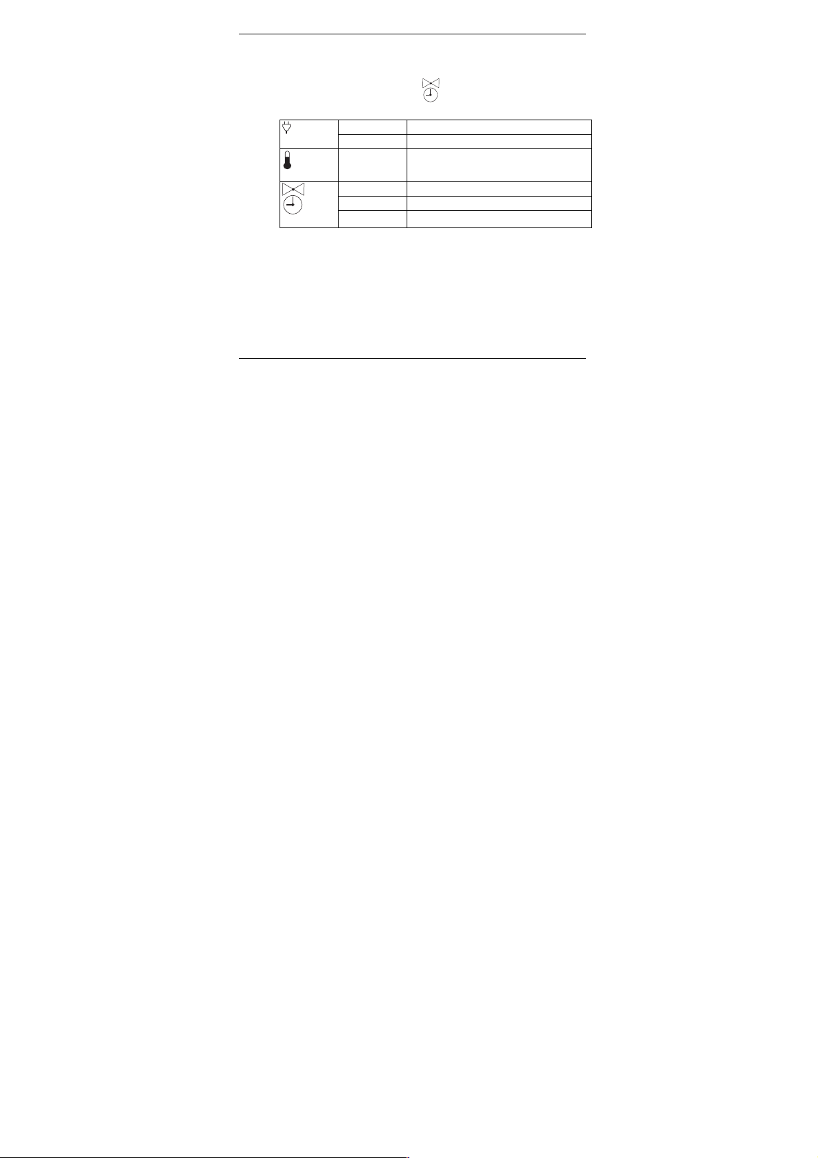
Checking installation
Configuration
► Press the configuration button (1) briefly.
The green LED illuminates if a temperature zone is assigned to
the central operating device.
The storey controller shows up in the device display.
The colours of LEDs 1 to 10 indicate the configuration of the
temperature zones.
(red)
(green)
43
Illuminating Setpoint adjuster or room temperature
sensor connected
Off No setpoint adjuster or room temperature
sensor assigned
Illuminating Room assigned to HCM 100
Off No assignment to HCM 100
Page 46

Start-up
Checking assignment of room names
► Maximise setpoint temperature at the central operating device (see
operating instructions of central operating device).
The green LED of the assigned temperature zone illuminates.
Actuators which are normally closed may experience a delay
of 15 minutes.
► Minimise setpoint temperature at the central operating device (see
operating instructions of central operating device).
The green LED of the assigned temperature zone goes out.
The assignment is correct.
Actuators which are normally open may experience a delay of
15 minutes.
Completing start-up
Closing open setpoint adjusters
► Replace cover and snap in both snap locks.
Handing over zoning plan
► Hand over the completed zoning plan and the installation instructions
to the customer. Both documents are important, as changes to the
system may be made in future.
44
Page 47

Start-up
Resetting storey controller to state of delivery
All current assignments are lost if the storey controller is reset
to the state of delivery.
► Press the configuration button (1) twice briefly.
► Press and hold the delete button (2) for approx. 20 seconds until all
LEDs illuminate briefly.
The storey controller is reset to the state of delivery.
Note to installer
After the storey controller has been started up, you should inform your
customer about the storey controller system:
► Familiarise your customer with the operation of the installed
components.
► Explain the manual operation of the components.
► Point out particular features and extension possibilities of the
respective customer installation.
45
Page 48

Appendix
Appendix
Glossary
Setpoint adjuster
Senses the actual temperature
and changes the setpoint
temperature. Installed in a userfriendly location in each zone.
Heating circuit
Area controlled by an actuator.
Central operating device
Central operating device HCM 100
of the storey controller HCE 40.
Boiler feedback
The storey controller HCE 40
controls the boiler feedback via
an analogue control device from
Honeywell. The boiler feedback to
Honeywell controllers MCR 200,
MCR 35, MCR 40 and ZG 252
could be done via an analogue
signal.
46
Setpoint temperature
Room temperature which is to be
reached.
Setpoint and temperature input
Function of the setpoint adjuster
in manual mode.
Thermal actuator
Opens and closes a heating
circuit. Controlled by the storey
controller.
Time program
Defined combination of setpoints
and switching points at the central
operating device.
Zoning plan
Overview of the temperature
zones of the storey controller.
Page 49

Appendix
Help with problems
Problem Cause/Solution
does not
LED
illuminate when power
plug is plugged in.
Red LED flashes in
normal mode.
Mains voltage not connected.
► Check whether electricity is available at
outlet.
Connection of setpoint adjuster or room
temperature sensor faulty.
► Ensure correct cabling to setpoint adjuster
or room temperature sensor.
► Check for broken cables or short circuits.
Green LED flashes in
normal mode.
Communication with central operating device
HCM 100 faulty.
► Check whether or not central operating
device is installed.
► Check whether or not a room name is
assigned to zone.
► Reassign zone if applicable.
► Ensure correct cabling between central
operating device HCM 100 and storey
controller.
47
Page 50

Appendix
Problem Cause/Solution
Not all rooms are
heated.
► Check heating and inlet temperature.
► Check adjuster on thermal actuator (see
"Setting actuator" on Page 22).
► Check actuator for correct operation.
All rooms to cold or all
rooms to warm.
Room name cannot be
assigned at central
operating device.
Room controlled
incorrectly.
► Check fuse (4 A, fast) inside of the
controller.
► Ensure correct cabling between central
operating device HCM 100 and storey
controller.
► Check whether adjusting ring of setpoint
adjuster is at position 0.
► Check whether adjusting ring can be
turned between –12 and +12 with housing
cover removed.
► Check whether or not a setpoint adjuster is
assigned to room.
► Ensure correct position of selector switch.
► Ensure correct setting (normally open/
closed) and connection of actuators.
48
Page 51

Appendix
(D)
49
Page 52

Appendix
Overview of heating components
A Setpoint adjuster HCW 23
Controls the setpoint temperature in each temperature zone via
an adjusting ring and integrated room temperature sensor
B Setpoint adjuster HCU 23
Controls the setpoint temperature in each temperature zone via
the adjusting ring, integrated room temperature sensor and time
program
C Central operating device HCM 100
Central operating device of the storey controller system
D Storey controller HCE 40
Controls actuators of floor heating/radiators; communicates with
setpoint adjusters and room temperature sensors
E Room temperature sensor RF 20 for storey controller
Transmits room temperature information to the storey controller
F Boiler feedback
G Pump relay HRel 1
H Thermal actuators
50
Page 53

Appendix
Zoning plan
Zone Actuator
(type, location)
1
2
3
4
5
Setpoint adjuster
(location)
Room name
51
Page 54

Appendix
Distribution limitation
• max. 5 zones per storey controller
• max. 3 connections per zone
• max. 10 actuators per storey controller
• only one type of thermal actuator per storey controller (open with
current or closed with current)
• max. 3 storey controllers of type HCE 40 can be connected to one
central operating device HCM 100.
• If a central operating device HCM 100 is installed, maximum one
setpoint adjuster HCU 23 can be connected to the storey connector
HCE 40.
52
Page 55

Page 56

Honeywell AG
Böblinger Straße 17
D – 71101 Schönaich
Tel. (+49) (0) 1801 466 390
The right is reserved to make modifications. This document is definitive for
the enclosed product and replaces all previous publications.
No. 7157588 EN1H-0186 GE51 R1002
This company is certificated to
 Loading...