

Page 1

®
equIP
Series 1080p
TDN Rugged Network
IR Bullet Camera
NTSC / PAL
HBD2FR1 HBD2FR1X
User Guide
Document 800-13338 – Rev A – 03/2013
Page 2

Page 3

User Guide
Page 4

Revisions
Issue Date Revisions
A 03/2013 New document.
Page 5

Cautions and Warnings
CAUTION: TO REDUCE THE RISK OF ELECTRIC SHOCK,
DO NOT REMOVE COVER (OR BACK).
NO USER SERVICEABLE PARTS INSIDE.
REFER SERVICING TO QUALIFIED SERVICE PERSONNEL.
THIS SYMBOL INDICATES
THAT DANGEROUSVOLTAGE
CONSTITUTING A RISK OF
ELECTRIC SHOCK IS PRESENT
WITHIN THE UNIT.
THIS SYMBOL INDICATES THAT
IMPORTANT OPERATING AND
MAINTENANCE INSTRUCTIONS
ACCOMPANY THIS UNIT.
DO NOT OPEN
RISK OF ELECTRIC SHOCK
| 5
WARNING
IR emitted from this product. Do not view directly
with optical instruments (magnifiers). Do not stare directly into the
lamp at a distance of less than 3.3 ft (1 m).
WARNING
To ensure compliance with electrical safety
standards, use an NRTL-listed PoE injector or network switch
meeting the IEEE 802.3af standard to power the camera.
CAUTION Class 1 LED product. Invisible LED radiation (850 nm).
Avoid exposure to beam.
CAUTION Installation and servicing should be performed only by
qualified and experienced technicians to conform to all local codes and to
maintain your warranty.
CAUTION Power over Ethernet (PoE) should meet the IEEE 802.3af PoE
standard.
CAUTION This equipment can only be powered via the Ethernet
cabling. A PoE injector or network switch with PoE support meeting the
IEEE 802.3af standard must be used.
800-13338 - A - 03/2013
Page 6

6 | HBD2FR1(X) User Guide
Regulatory Statements
FCC Compliance Statement
Information to the User This equipment has been tested and found to comply with the limits
for a Class A digital device, pursuant to part 15 of the FCC Rules. These limits are designed to
provide reasonable protection against harmful interference when the equipment is operated in
a commercial environment. This equipment generates, uses, and can radiate radio frequency
energy and, if not installed and used in accordance with the instruction manual, may cause
harmful interference to radio communications. Operation of this equipment in a residential area
is likely to cause harmful interference in which case the user will be required to correct the
interference at his own expense.
Changes or modifications not expressly approved by the party responsible for compliance
could void the user’s authority to operate the equipment.
Canadian Compliance Statement
This Class A digital apparatus complies with Canadian ICES-003.
Cet appareil numérique de la Classe A est conforme à la norme NMB-003 du Canada.
Manufacturer’s Declaration of Conformance
North America The equipment supplied with this guide conforms to UL 60950-1 and
CSA C22.2 No. 60950-1.
Europe The manufacturer declares that the equipment supplied is compliant with the essential
requirements of the EMC directive 2004/108/EC, conforming to the requirements of standards
EN 55022 for emissions, EN 50130-4 for immunity, and EN 60950-1 for electrical equipment
safety.
Waste Electrical and Electronic Equipment (WEEE)
Correct Disposal of this Product (applicable in the European Union and other
European countries with separate collection systems).
This product should be disposed of, at the end of its useful life, as per applicable
local laws, regulations, and procedures.
www.honeywellvideo.com
Page 7

Safety Instructions
Before installing or operating the unit, read and follow all instructions. After installation, retain the safety and operating instructions for future reference.
1. HEED WARNINGS - Adhere to all warnings on the unit and in the operating instructions.
2. INSTALLATION
• Install in accordance with the manufacturer’s instructions.
• Installation and servicing should be performed only by qualified and experienced technicians to
conform to all local codes and to maintain your warranty.
• Do not install the unit in an extremely hot or humid location, or in a place subject to dust or
mechanical vibration. The unit is not designed to be waterproof. Exposure to rain or water may
damage the unit.
• Any wall or ceiling mounting of the product should follow the manufacturer’s instructions and
use a mounting kit approved or recommended by the manufacturer.
3. POWER SOURCES - This product should be operated only from the type of power source indicated
on the marking label. If you are not sure of the type of power supplied to your facility, consult your
product dealer or local power company.
4. HEAT - Situate away from items that produce heat or are heat sources such as radiators, heat
registers, stoves, or other products (including amplifiers).
5. WATER AND MOISTURE - Do not use this unit near water or in an unprotected outdoor installation,
or any area classified as a wet location.
6. MOUNTING SYSTEM - Use only with a mounting system recommended by the manufacturer, or sold
with the product.
7. ATTACHMENTS - Do not use attachments not recommended by the product manufacturer as they
may result in the risk of fire, electric shock, or injury to persons.
8. ACCESSORIES - Only use accessories specified by the manufacturer.
9. CLEANING - Do not use liquid cleaners or aerosol cleaners. Use a damp cloth for cleaning.
10. SERVICING - Do not attempt to service this unit yourself as opening or removing covers may expose
you to dangerous voltage or other hazards. Refer all servicing to qualified service personnel.
11. REPLACEMENT PARTS - When replacement parts are required, be sure the service technician has
used replacement parts specified by the manufacturer or have the same characteristics as the original
part. Unauthorized substitutions may result in fire, electric shock or other hazards. Using replacement
parts or accessories other than the original manufacturers may invalidate the warranty.
12. DAMAGE REQUIRING SERVICE - Unplug the unit from the outlet and refer servicing to qualified
service personnel under the following conditions:
• When the power-supply cord or plug is damaged.
• If liquid has been spilled, or objects have fallen into the unit.
• If the unit has been exposed to rain or water.
• If the unit does not operate normally by following the operating instructions. Adjust only those
controls that are covered by the operating instructions as an improper adjustment of other
controls may result in damage and will often require extensive work by a qualified technician to
restore the unit to its normal operation.
• If the unit has been dropped or the enclosure has been damaged.
• When the unit exhibits a distinct change in performance - this indicates a need for service.
13. SAFETY CHECK - Upon completion of any service or repairs to this unit, ask the service technician to
perform safety checks to determine that the unit is in proper operating condition.
| 7
800-13338 - A - 03/2013
Page 8

8 | HBD2FR1(X) User Guide
Warranty and Service
Subject to the terms and conditions listed on the Product warranty, during the warranty period
Honeywell will repair or replace, at its sole option, free of charge, any defective products
returned prepaid.
In the event that you have a problem with any Honeywell product, please call Customer Service
at 1.800.323.4576 for assistance or to request a Return Merchandise Authorization (RMA)
number.
Be sure to have the model number, serial number, and the nature of the problem available for
the technical service representative.
Prior authorization must be obtained for all returns, exchanges, or credits. Items shipped to
Honeywell without a clearly identified Return Merchandise Authorization (RMA) number
may be refused.
www.honeywellvideo.com
Page 9

Contents | 9
Contents 1
About This Document . . . . . . . . . . . . . . . . . . . . . . . . . . . . . . . . . . . . . . . . . . . . . 15
Overview of Contents. . . . . . . . . . . . . . . . . . . . . . . . . . . . . . . . . . . . . . . . . . . . . 15
Related Documents . . . . . . . . . . . . . . . . . . . . . . . . . . . . . . . . . . . . . . . . . . . . . 16
Typographical Conventions . . . . . . . . . . . . . . . . . . . . . . . . . . . . . . . . . . . . . . . . . 16
1 Introduction . . . . . . . . . . . . . . . . . . . . . . . . . . . . . . . . . . . . . . . . . . . . . . . 17
Features . . . . . . . . . . . . . . . . . . . . . . . . . . . . . . . . . . . . . . . . . . . . . . . . . 17
2 Installing the Camera . . . . . . . . . . . . . . . . . . . . . . . . . . . . . . . . . . . . . . . . . . 19
Before You Begin . . . . . . . . . . . . . . . . . . . . . . . . . . . . . . . . . . . . . . . . . . . . . . . 19
Parts of the Camera . . . . . . . . . . . . . . . . . . . . . . . . . . . . . . . . . . . . . . . . . . . . . 20
Mounting the Camera . . . . . . . . . . . . . . . . . . . . . . . . . . . . . . . . . . . . . . . . . . . . 20
Mounting the Camera to a Wall or Ceiling . . . . . . . . . . . . . . . . . . . . . . . . . . . . . . . 20
Mounting the Camera to a 4S Electrical Box . . . . . . . . . . . . . . . . . . . . . . . . . . . . . . 21
Connecting the Cables . . . . . . . . . . . . . . . . . . . . . . . . . . . . . . . . . . . . . . . . . . . . 21
Power over Ethernet (PoE) . . . . . . . . . . . . . . . . . . . . . . . . . . . . . . . . . . . . . . . 21
Audio and Alarms . . . . . . . . . . . . . . . . . . . . . . . . . . . . . . . . . . . . . . . . . . . . 22
Positioning the Camera. . . . . . . . . . . . . . . . . . . . . . . . . . . . . . . . . . . . . . . . . . . . 23
Sunshield . . . . . . . . . . . . . . . . . . . . . . . . . . . . . . . . . . . . . . . . . . . . . . . . 23
Setting Focus and Zoom . . . . . . . . . . . . . . . . . . . . . . . . . . . . . . . . . . . . . . . . . . . 24
3 Installing the Honeywell IP Utility . . . . . . . . . . . . . . . . . . . . . . . . . . . . . . . . . . . 25
About the Honeywell IP Utility . . . . . . . . . . . . . . . . . . . . . . . . . . . . . . . . . . . . . . . . 25
Installing the Honeywell IP Utility. . . . . . . . . . . . . . . . . . . . . . . . . . . . . . . . . . . . . . . 27
Before You Begin . . . . . . . . . . . . . . . . . . . . . . . . . . . . . . . . . . . . . . . . . . . . 27
Installing the IP Utility . . . . . . . . . . . . . . . . . . . . . . . . . . . . . . . . . . . . . . . . . . 27
Connecting to a Camera . . . . . . . . . . . . . . . . . . . . . . . . . . . . . . . . . . . . . . . . . . . 29
Configuring the Camera’s IP Network Settings . . . . . . . . . . . . . . . . . . . . . . . . . . . . . . . 30
Changing the Camera’s Password. . . . . . . . . . . . . . . . . . . . . . . . . . . . . . . . . . . . . . 32
Using an ONVIF IP Device with a Network Video Recorder . . . . . . . . . . . . . . . . . . . . . . . . .33
Uninstalling the Honeywell IP Utility . . . . . . . . . . . . . . . . . . . . . . . . . . . . . . . . . . . . . 33
4 Setting Up the Camera . . . . . . . . . . . . . . . . . . . . . . . . . . . . . . . . . . . . . . . . . 35
About the Web Client . . . . . . . . . . . . . . . . . . . . . . . . . . . . . . . . . . . . . . . . . . . . . 35
Before You Begin . . . . . . . . . . . . . . . . . . . . . . . . . . . . . . . . . . . . . . . . . . . . . . . 36
Preparing for ActiveX Installation (Internet Explorer Only) . . . . . . . . . . . . . . . . . . . . . . .36
Starting the Web Client . . . . . . . . . . . . . . . . . . . . . . . . . . . . . . . . . . . . . . . . . . . . 40
Viewing Live Video . . . . . . . . . . . . . . . . . . . . . . . . . . . . . . . . . . . . . . . . . . . . . . 43
Taking a Snapshot. . . . . . . . . . . . . . . . . . . . . . . . . . . . . . . . . . . . . . . . . . . . 43
Configuring Camera Settings . . . . . . . . . . . . . . . . . . . . . . . . . . . . . . . . . . . . . . . . 44
Basic Camera Setup Process . . . . . . . . . . . . . . . . . . . . . . . . . . . . . . . . . . . . . . 45
Setting Auto Exposure. . . . . . . . . . . . . . . . . . . . . . . . . . . . . . . . . . . . . . . . . . 46
Setting Day/Night and IR . . . . . . . . . . . . . . . . . . . . . . . . . . . . . . . . . . . . . . . . 47
Setting White Balance . . . . . . . . . . . . . . . . . . . . . . . . . . . . . . . . . . . . . . . . . . 48
Configuring Compression Settings . . . . . . . . . . . . . . . . . . . . . . . . . . . . . . . . . . . . . 48
Configuring Priority Settings. . . . . . . . . . . . . . . . . . . . . . . . . . . . . . . . . . . . . . . 51
800-13338 - A - 03/2013
Page 10

10 | HBD2FR1(X) User Guide
Configuring Zoom and Focus . . . . . . . . . . . . . . . . . . . . . . . . . . . . . . . . . . . . . . . . 54
Zoom. . . . . . . . . . . . . . . . . . . . . . . . . . . . . . . . . . . . . . . . . . . . . . . . . . . 54
Focus . . . . . . . . . . . . . . . . . . . . . . . . . . . . . . . . . . . . . . . . . . . . . . . . . . 55
Configuring Audio . . . . . . . . . . . . . . . . . . . . . . . . . . . . . . . . . . . . . . . . . . . . . . 55
Camera-to-Client Settings . . . . . . . . . . . . . . . . . . . . . . . . . . . . . . . . . . . . . . . . 56
Client-to-Camera Settings . . . . . . . . . . . . . . . . . . . . . . . . . . . . . . . . . . . . . . . . 56
Configuring Alarms . . . . . . . . . . . . . . . . . . . . . . . . . . . . . . . . . . . . . . . . . . . . . . 57
Alarm Input and Output . . . . . . . . . . . . . . . . . . . . . . . . . . . . . . . . . . . . . . . . . 57
Configuring Video Analytics . . . . . . . . . . . . . . . . . . . . . . . . . . . . . . . . . . . . . . . . . 58
Setting Tamper Detection . . . . . . . . . . . . . . . . . . . . . . . . . . . . . . . . . . . . . . . . 59
Setting Video Motion Detection (VMD) . . . . . . . . . . . . . . . . . . . . . . . . . . . . . . . . . 60
Configuring Date and Time. . . . . . . . . . . . . . . . . . . . . . . . . . . . . . . . . . . . . . . . . . 65
Setting the Time Zone . . . . . . . . . . . . . . . . . . . . . . . . . . . . . . . . . . . . . . . . . . 65
Setting the Network Time Protocol (NTP) Server . . . . . . . . . . . . . . . . . . . . . . . . . . . .65
Overlay Settings . . . . . . . . . . . . . . . . . . . . . . . . . . . . . . . . . . . . . . . . . . . . . 70
System Setup. . . . . . . . . . . . . . . . . . . . . . . . . . . . . . . . . . . . . . . . . . . . . . . . . 71
Setting the Port Allocation . . . . . . . . . . . . . . . . . . . . . . . . . . . . . . . . . . . . . . . . 71
Setting the Snapshot File Type and Path (Internet Explorer Only) . . . . . . . . . . . . . . . . . . . 72
Resetting and Rebooting the Camera. . . . . . . . . . . . . . . . . . . . . . . . . . . . . . . . . . 72
Viewing Device Information . . . . . . . . . . . . . . . . . . . . . . . . . . . . . . . . . . . . . . . . . 73
Logging Out of the Web Client . . . . . . . . . . . . . . . . . . . . . . . . . . . . . . . . . . . . . . . . 74
Uninstalling Honeywell ONVIF ActiveX (Internet Explorer) . . . . . . . . . . . . . . . . . . . . . . . . . 74
Uninstalling VLC Media Player (Chrome and Firefox) . . . . . . . . . . . . . . . . . . . . . . . . . . . . 74
A Troubleshooting. . . . . . . . . . . . . . . . . . . . . . . . . . . . . . . . . . . . . . . . . . . . . 75
B Specifications . . . . . . . . . . . . . . . . . . . . . . . . . . . . . . . . . . . . . . . . . . . . . . 77
www.honeywellvideo.com
Page 11

Figures | 11
Figures 1
Figure 2-1 Normal Open States . . . . . . . . . . . . . . . . . . . . . . . . . . . . . . . . . . . . . . . . 22
Figure 2-2 Alarm Connection . . . . . . . . . . . . . . . . . . . . . . . . . . . . . . . . . . . . . . . . . 23
Figure 3-1 Overview of Honeywell IP Utility User Interface . . . . . . . . . . . . . . . . . . . . . . . . . . 26
Figure 3-2 IP Utility User Interface. . . . . . . . . . . . . . . . . . . . . . . . . . . . . . . . . . . . . . . 28
Figure 3-3 ONVIF Login Window . . . . . . . . . . . . . . . . . . . . . . . . . . . . . . . . . . . . . . . 29
Figure 3-4 IP Network Settings Configuration . . . . . . . . . . . . . . . . . . . . . . . . . . . . . . . . 31
Figure 3-5 Camera Password Configuration . . . . . . . . . . . . . . . . . . . . . . . . . . . . . . . . . 32
Figure 4-1 Windows Firewall Settings. . . . . . . . . . . . . . . . . . . . . . . . . . . . . . . . . . . . . 36
Figure 4-2 Preferred UAC Settings . . . . . . . . . . . . . . . . . . . . . . . . . . . . . . . . . . . . . . 37
Figure 4-3 Run IE as Administrator . . . . . . . . . . . . . . . . . . . . . . . . . . . . . . . . . . . . . . 37
Figure 4-4 Trusted Sites Configuration Page . . . . . . . . . . . . . . . . . . . . . . . . . . . . . . . . . 38
Figure 4-5 Adding a Subnet to Trusted Sites . . . . . . . . . . . . . . . . . . . . . . . . . . . . . . . . . 39
Figure 4-6 Allowing IE through the Firewall . . . . . . . . . . . . . . . . . . . . . . . . . . . . . . . . . . 39
Figure 4-7 Live View . . . . . . . . . . . . . . . . . . . . . . . . . . . . . . . . . . . . . . . . . . . . . . 43
Figure 4-8 Camera Setup View . . . . . . . . . . . . . . . . . . . . . . . . . . . . . . . . . . . . . . . . 45
Figure 4-9 Compression Setup View . . . . . . . . . . . . . . . . . . . . . . . . . . . . . . . . . . . . . 48
Figure 4-10 Codec Type . . . . . . . . . . . . . . . . . . . . . . . . . . . . . . . . . . . . . . . . . . . . 49
Figure 4-11 Primary Stream Settings (H.264) . . . . . . . . . . . . . . . . . . . . . . . . . . . . . . . . . 49
Figure 4-12 Secondary Stream Settings (H.264 or MJPEG) . . . . . . . . . . . . . . . . . . . . . . . . . .50
Figure 4-13 Zoom and Focus View . . . . . . . . . . . . . . . . . . . . . . . . . . . . . . . . . . . . . . . 54
Figure 4-14 Audio Setup View . . . . . . . . . . . . . . . . . . . . . . . . . . . . . . . . . . . . . . . . . 55
Figure 4-15 Alarm Setup View . . . . . . . . . . . . . . . . . . . . . . . . . . . . . . . . . . . . . . . . . 57
Figure 4-16 Video Analytics View . . . . . . . . . . . . . . . . . . . . . . . . . . . . . . . . . . . . . . . . 58
Figure 4-17 Video Analytics Alarm Message . . . . . . . . . . . . . . . . . . . . . . . . . . . . . . . . . . 58
Figure 4-18 VMD Configuration (Low Motion Threshold - 30%) . . . . . . . . . . . . . . . . . . . . . . . .63
Figure 4-19 VMD Configuration (Medium Motion Threshold - 50%) . . . . . . . . . . . . . . . . . . . . . . 63
Figure 4-20 VMD Configuration (High Motion Threshold - 80%). . . . . . . . . . . . . . . . . . . . . . . .64
Figure 4-21 VMD Configuration - Combination Setup . . . . . . . . . . . . . . . . . . . . . . . . . . . . . 64
Figure 4-22 Date and Time View . . . . . . . . . . . . . . . . . . . . . . . . . . . . . . . . . . . . . . . . 65
Figure 4-23 System Setup View . . . . . . . . . . . . . . . . . . . . . . . . . . . . . . . . . . . . . . . . 71
Figure 4-24 Device Information View . . . . . . . . . . . . . . . . . . . . . . . . . . . . . . . . . . . . . . 73
800-13338 - A - 03/2013
Page 12

12 | HBD2FR1(X) User Guide
www.honeywellvideo.com
Page 13

Tables | 13
Tables 1
Table 2-1 Parts List . . . . . . . . . . . . . . . . . . . . . . . . . . . . . . . . . . . . . . . . . . . . . . 19
Table 3-1 IP Network Settings Options . . . . . . . . . . . . . . . . . . . . . . . . . . . . . . . . . . . . 30
Table 4-1 Default Camera User Names and Passwords . . . . . . . . . . . . . . . . . . . . . . . . . . .35
Table 4-2 Auto Exposure Settings. . . . . . . . . . . . . . . . . . . . . . . . . . . . . . . . . . . . . . . 46
Table 4-3 Day/Night Settings . . . . . . . . . . . . . . . . . . . . . . . . . . . . . . . . . . . . . . . . . 47
Table 4-4 White Balance Settings . . . . . . . . . . . . . . . . . . . . . . . . . . . . . . . . . . . . . . . 48
Table 4-5 Video Stream Configurations . . . . . . . . . . . . . . . . . . . . . . . . . . . . . . . . . . . . 49
Table 4-6 Codec Configurations and CVBS Availability . . . . . . . . . . . . . . . . . . . . . . . . . . . 49
Table 4-7 Compression Settings . . . . . . . . . . . . . . . . . . . . . . . . . . . . . . . . . . . . . . . 50
Table 4-8 Priority Settings . . . . . . . . . . . . . . . . . . . . . . . . . . . . . . . . . . . . . . . . . . . 51
Table 4-9 Range of User-Definable Bit Rate Values. . . . . . . . . . . . . . . . . . . . . . . . . . . . . . 52
800-13338 - A - 03/2013
Page 14

14 | HBD2FR1(X) User Guide
www.honeywellvideo.com
Page 15

About This Document
This document contains instructions for installing, configuring, and operating the Honeywell
®
Series HBD2FR1(X) network camera.
equIP
This document is intended for system installers, administrators, and operators.
Overview of Contents
This document contains the following chapters and appendixes:
• Chapter 1, Introduction, introduces the HBD2FR1(X).
• Chapter 2, Installing the Camera, describes how to mount the camera, connect the cables,
and adjust the camera’s field of view.
• Chapter 3, Installing the Honeywell IP Utility, describes how to install the Honeywell IP
Utility, connect to a network camera, configure the camera’s IP network settings, and
change the camera’s password.
• Chapter 4, Setting Up the Camera, describes how to configure camera settings using the
web client.
• Appendix A, Troubleshooting, lists solutions to problems encountered during installation.
• Appendix B, Specifications, lists the specifications of the HBD2FR1(X).
800-13338 - A - 03/2013
Page 16

16 | HBD2FR1(X) User Guide
Related Documents
For more information, please refer to the following documents:
Document title Part number Description
equIP® Series HBD2FR1(X) 1080p TDN Network
IR Bullet Camera Quick Installation Guide
800-13339 Installation guide
Typographical Conventions
This document uses the following typographical conventions:
Font What it represents Example
Helvetica
Lucida Values of editable fields that are mentioned in the
Swiss721 BT Bold Words or characters that you must type. The word
Keys on the keyboard Press Ctrl+C
The Time from field can be set to
body text of the document for reference purposes,
but do not need to be entered as part of a procedure
Text strings displayed on the screen
Syntax
“enter” is used if you must type text and then press
Enter or Return key.
the
Hours:Minute:Seconds.
The message Unauthorized displays.
(object) entered
Enter the password.
Menu titles and other items you select Double-click Open from the File menu.
Buttons you click to perform actions Click Exit to close the program.
Italic Placeholders: words that vary depending on the
situation
Cross-reference to external source Refer to the System Administrator Guide.
Cross-reference within document See Chapter 2, Installation.
www.honeywellvideo.com
Enter your user name.
Page 17

1
Introduction 1
Honeywell’s ONVIF IR HBD2FR1(X) network camera provides high quality video surveillance
over a network connection.
Features
• Outstanding image quality, 1080p (1920 x 1080) resolution
• 30 fps (25 fps PAL) progressive scan
• True day/night, 3–9 mm VFAI MFZ lens with removable IR cut filter
• 48 LEDs provide up to 100 ft (30 m) of illumination, depending on scene reflectance
• Camera tamper detection
• Video motion detection
• NTP time synchronization support
• ONVIF support (Profile S)
• Programmable daylight threshold settings to deliver color or black/white images.
• Dual digital video streams, independently configurable, H.264 and/or H.264/MJPEG
• Remote firmware updates
• Supports both dynamic and static IP addresses
• Date and time stamp embedded in video stream
• Multiple browser support (Microsoft Internet Explorer, Google Chrome, Mozilla Firefox)
• Advanced IP Utility software for easy system setup
• Embedded web server for remote setup of camera video and network parameters
• Power over Ethernet (IEEE 802.3af) power input
• Supports input and output alarm contacts
• Supports bidirectional audio
• IP66 ingress protection rating
• Built-in breather vent
• Adapter plate for installation to 4S electrical box
• Multi-directional mounting bracket and sunshield
800-13338 - A - 03/2013
Page 18

18 | HBD2FR1(X) User Guide
www.honeywellvideo.com
Page 19

2
Installing the Camera 2
This chapter describes how to:
•Mount the camera (page 20)
• Connect the cables (page 21)
• Position the camera (page 23)
• Set focus and zoom (page 24)
Before You Begin
Check that the items received match those listed on the order form and packing slip. Your
camera packing box should include the following items:
Table 2-1 Parts List
Qty Item
1 Camera unit
1 Hardware kit:
1 Local video (AUX) output cable
1 Mounting template ("Guide Pattern")
1 Adapter plate for mounting camera to a 4S electrical box
1 Software DVD (includes user guide)
1 Quick installation guide (800-13339)
1Product warranty
• M5×20 machine screws (4)
•Nuts (4)
• Tamperproof Allen key (1)
If any parts are missing or damaged, contact the dealer you purchased the camera from or call
Honeywell Customer Service.
800-13338 - A - 03/2013
Page 20
20 | HBD2FR1(X) User Guide
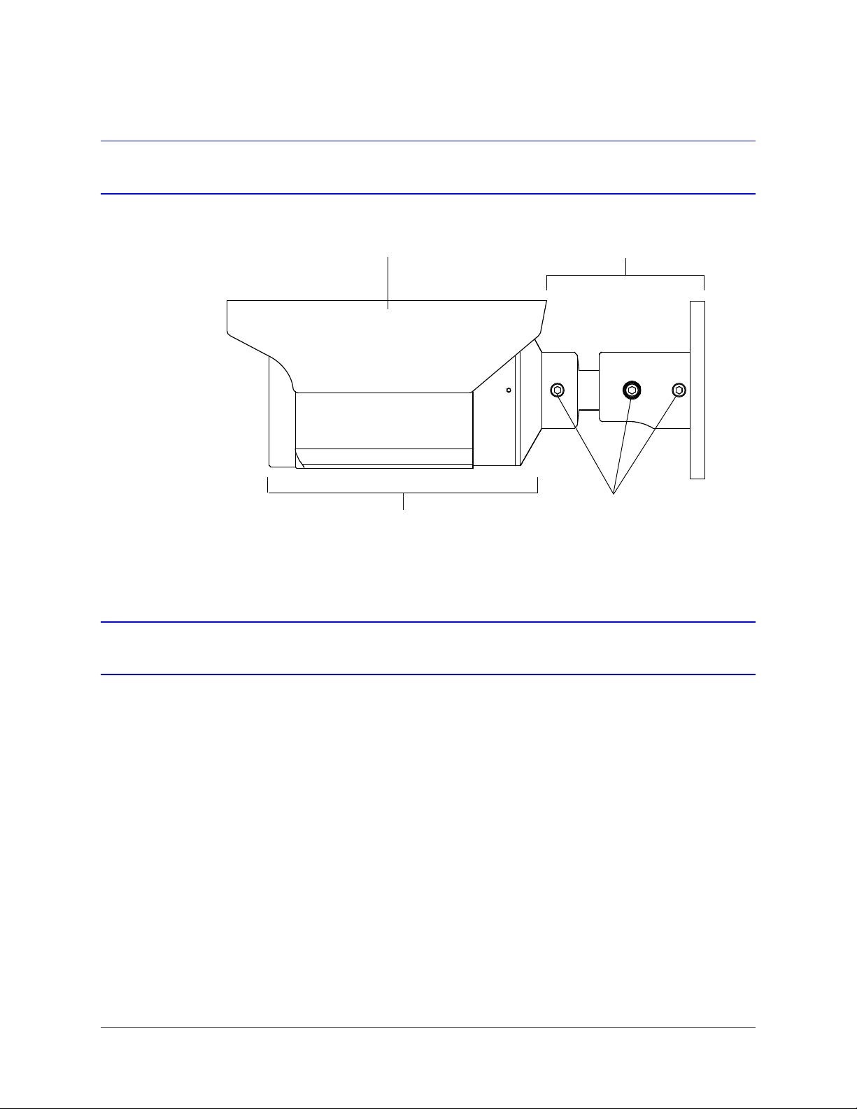
Sunshield Bracket
Camera Body
Adjustment
Screws
Parts of the Camera
Mounting the Camera
You can mount the camera to a wall, ceiling, or to a 4S electrical box using the supplied adapter
plate. The mounting surface must be flat and capable of supporting the combined weight of the
camera, sunshield, and mounting bracket (approximately 3.92 lb. [1.78 kg]).
Mounting the Camera to a Wall or Ceiling
To mount the camera to a wall or ceiling
1. Pre-drill four holes in the mounting surface using the supplied template as a guide.
2. Attach the bracket to the mounting surface using suitable mounting hardware (not
supplied).
www.honeywellvideo.com
Page 21

Mounting the Camera to a 4S Electrical Box
4S Box
Adapter Plate
To mount the camera to a 4S box using the adapter plate
1. Attach the base of the camera mounting bracket to the supplied adapter plate using the
four supplied M5×20 machine screws and nuts.
2. Attach the adapter plate to a 4-inch square electrical box using suitable mounting
hardware (not supplied).
Note 4S boxes have either two or four screw holes.
Installing the Camera | 21
Connecting the Cables
Power over Ethernet (PoE)
Connect a Category 5/5e Ethernet cable to the RJ45 jack on the camera’s PoE cable to create
a network connection and to power the camera.
WARNING
standards, use an NRTL-listed PoE injector or network switch
meeting the IEEE 802.3af standard to power the camera.
To ensure compliance with electrical safety
800-13338 - A - 03/2013
Page 22

22 | HBD2FR1(X) User Guide
Alarm
IN+ Yellow
IN– Green
OUT+ Blue
OUT– White
Audio
IN+ Orange
IN– Red
OUT+ Brown
OUT– Black
Normally closed
Normally opened
Audio and Alarms
Connect the audio and alarm wires.
Connecting Audio
The camera supports bidirectional audio. There are two supported voice band channels that
function in full duplex mode. The camera can transmit audio from the camera to the client (PC)
using any audio source that provides an industry-standard line-level input.
The camera can also receive audio from the client (PC) and provide an industry-standard
line-level output suitable to connect to audio devices.
Audio input and output have 600 ohm impedance. See Configuring Audio on page 55 to
configure audio options.
Connecting Alarms
The camera has one alarm input and one alarm output. Connect mechanical or electrical
switches to the alarm input connection to enable event-triggered recording. An alarm is
triggered when the normal alarm state (open or closed) changes (see Figure 2-1).
Figure 2-1 Normal Open States
www.honeywellvideo.com
See Configuring Alarms on page 57 to configure the alarm input.
Connect external devices, such as sirens or flashing lights, to the alarm output connector to
signal to the user that an alarm is activated. The alarm output can be configured to provide
normally open or normally closed contacts.
Page 23

Figure 2-2 Alarm Connection
+
–
In
Audio
Alarm
Out
+
See Configuring Alarms on page 57 to configure the alarm output.
Positioning the Camera
Installing the Camera | 23
Sunshield
Position the camera to achieve the desired view. To adjust the camera’s position, loosen the
bracket screws with the supplied Allen key, reposition the camera, and then tighten the screws.
The camera comes with a sunshield already installed. If you want, you can reposition the
sunshield or you can remove it. To reposition the sunshield, slide the sunshield forward or
backward as required.
800-13338 - A - 03/2013
Page 24

24 | HBD2FR1(X) User Guide
VIDEO
TELE
NEARFAR
WIDE
FOCUS
(PRESS)
* Not currently supported.
Reserved for future use.
*
Setting Focus and Zoom
You can set the camera’s focus and zoom locally or remotely.
To set the focus and zoom locally
1. Unscrew the cap on the underside of the camera using a coin.
2. Connect the supplied video output cable to the
VIDEO 2-pin connector. Connect the other end of
the cable to a spot monitor.
3. To set the focus, move the built-in joystick to NEAR
to focus near or to FAR to focus far
4. To set the zoom (field of view), move the built-in
joystick to TELE to zoom in or to WIDE to zoom
out.
5. Disconnect the video output cable from VIDEO,
and then replace the cap on the underside of the
camera.
Note To set focus and zoom remotely, see Configuring Zoom and Focus on page 54.
www.honeywellvideo.com
Page 25

3
Installing the Honeywell IP Utility 3
This chapter describes how to:
• Install the IP Utility (page 27)
• Connect to a HBD2FR1(X) camera (page 29)
• Configure the camera’s network settings (page 30)
• Change the camera’s password (page 32)
• Uninstall the IP Utility (page 33)
About the Honeywell IP Utility
The Honeywell IP Utility is a software application used to discover and configure equIP Series
and Performance Series products residing on an IP network. Using the IP Utility, you can
change your HBD2FR1(X) camera’s network settings (including device name), upgrade the
camera’s firmware, and manage the camera’s user settings. You can also use the utility to
launch a web client application in your browser that lets you view live video and access
additional camera configuration settings.
For an overview of the Honeywell IP Utility interface, see Figure 3-1.
800-13338 - A - 03/2013
Page 26

26 | HBD2FR1(X) User Guide
The About menu displays the
software version installed.
The Status bar displays how many
devices are on the network, which
one you are connected to, and
which user is logged on.
The Discovery pane lists
the IP devices found on the
network and groups by
device type.
From the User tab, Administrators
can change the web client user
passwords.
Connect button
Disconnect button
Limited/No connectivity
button
Refresh button
Use the Product Filter drop-down
menu to select a specific device,
such as all H3D1F cameras.
Use Batch Firmware Upgrade
to select a group of devices and
upgrade the firmware for all.
Figure 3-1 Overview of Honeywell IP Utility User Interface
www.honeywellvideo.com
Page 27

Installing the Honeywell IP Utility
You can install the IP Utility from the DVD that came with your camera or you can download the
latest version from Honeywell’s Download Center (recommended):
http://www.honeywellsystems.com/support/download-center/index.html
To receive a user name and password for accessing the Download Center, contact the
customer service center within your region. This information is provided on the Download
Center webpage.
Note If you have an older version of Honeywell IP Utility installed on your computer you
may need to uninstall it before you can install the new version. For instructions on
how to uninstall the IP Utility, see Uninstalling the Honeywell IP Utility on page 33.
Installing the Honeywell IP Utility | 27
Before You Begin
Before you begin installing the IP Utility, do the following:
1. Ensure that your workstation meets the following system requirements:
Operating System Windows XP Professional, SP3
CPU Pentium 4, 3.1 GHz or faster
System Memory 1 GB (32 bit) or 2 GB (64 bit)
2. Ensure that you have Windows administrator privileges for the workstation on which you
are installing the IP Utility.
3. Confirm that your camera is connected to the network (see Connecting the Cables on
page 21).
Installing the IP Utility
The IP Utility is installed on your workstation using InstallShield. When you install the IP Utility,
a networking protocol (Bonjour) is also installed that enables the automatic discovery of IP
network devices.
Windows Server 2003 R2 (32 bit)
Windows Vista, SP1
Windows 7 (32/64 bit)
Windows Server 2008 R2 (64 bit)
800-13338 - A - 03/2013
Page 28

28 | HBD2FR1(X) User Guide
To install the IP Utility
1. Close any open applications. If you are using Norton AntiVirus software, disable it.
2. Do one of the following:
Install from DVD Install from Website
• Insert the DVD that was shipped with
4. Follow the InstallShield wizard’s on-screen instructions to complete the installation.
5. Open the IP Utility by double-clicking the Honeywell IP Utility icon on the desktop.
The IP Utility opens on your desktop (see Figure 3-2).
your camera into your workstation’s
DVD-ROM drive.
If the InstallShield wizard does not
open automatically, browse to [DVD
drive]\Honeywell_IP_Utility\ and
double-click Honeywell_IP_Utility_
Setup.exe.
1. Go to www.honeywellsystems.com/
support/download-center/index.html.
2. Follow the instructions on the page to
log in and find your camera.
3. Run the InstallShield wizard.
Figure 3-2 IP Utility User Interface
www.honeywellvideo.com
Page 29

Connecting to a Camera
When you open the IP Utility, the devices on the network — including devices on other
subnets—are automatically discovered and listed in the Discovery pane on the left of the
screen. After the initial discovery, the list of discovered devices auto-refreshes at regular
intervals. You can manually refresh the list by clicking (Refresh).
To connect to a network camera
•In the Discovery pane, double-click the camera you want to connect to. Alternatively, click
the camera name, and then click (Connect).
When connecting to an ONVIF camera for the first time, the ONVIF credentials login
window appears (see Figure 3-3). Enter your user name and password, and then click OK.
Figure 3-3 ONVIF Login Window
Installing the Honeywell IP Utility | 29
If the connection is successful, the message Connected to Device [device name]
appears in the status bar at the bottom of the screen.
If the connection is unsuccessful, (Limited/No Connectivity) replaces (Connect) in the
Discovery pane. Check the the network settings of the camera and the workstation. The camera
must be on the same subnet as the workstation. Contact your network administrator for
additional support.
To disconnect from a network camera
•In the Discovery pane, click the camera you want to disconnect from, and then click
(Disconnect).
If you try to disconnect without saving configuration details, you will be prompted to save
your changes. Click Yes to save the changes and disconnect. Click Cancel to discard the
changes and disconnect.
800-13338 - A - 03/2013
Page 30

30 | HBD2FR1(X) User Guide
Configuring the Camera’s IP Network Settings
You can configure a connected camera’s IP network settings either automatically or manually
using the IP Utility. Contact your network administrator if you experience any network-related
issues or if you have questions about your network.
Table 3-1 IP Network Settings Options
Option Description
Device Name By default, the device name is the device type plus the MAC address. For
MAC Address A unique address assigned to the device in the factory. Not configurable.
IP Address The IP address of the device on the network. The camera can be assigned a
Subnet Mask The subnet mask, or netmask, value of the device on the network. IP networks
Default Gateway The default gateway address that connects the device to the network. The
security purposes it is recommended that you change the device name.
static or a dynamic IP address. A static IP address is assigned by the user. A
dynamic IP address is assigned automatically by a DHCP or APIPA service.
can be subdivided into a series of smaller networks called subnets. When a
network is subnetted, the subnet mask specifies which smaller network (subnet)
the device belongs to. If the subnet mask is incorrect, the camera cannot
communicate with other devices on the network.
gateway allows communication between devices on different networks. If the
gateway is incorrect, the camera cannot communicate with other devices that
are not in the same network address range.
To configure the camera’s network settings automatically
1. Connect to the camera (see Connecting to a Camera on page 29).
2. In the System tab, under IP Network Settings, confirm that the Obtain an IP address
automatically check box is selected.
3. Enter a descriptive name for the camera in the Device Name field. For example,
FrontLobbyDome01. (By default, the device name is the device type plus the MAC
address.)
4. Click Apply to save the changes.
The network automatically assigns the IP address based on the DHCP network server
details. If no DHCP server is present on the network, the camera defaults to an APIPA
address (169.254.x.x).
To configure the camera’s network settings manually
1. Connect to the camera (see Connecting to a Camera on page 29).
2. In the System tab, under IP Network Settings, clear the Obtain an IP Address
www.honeywellvideo.com
automatically check box.
Page 31

Installing the Honeywell IP Utility | 31
Figure 3-4 IP Network Settings Configuration
3. Enter a descriptive name for the camera in the Device Name field. For example,
FrontLobbyDome01. (By default, the device name is the device type plus the MAC
address.)
4. Enter values for the IP Address, Subnet Mask, and Default Gateway (see Table 3-1).
The MAC address is a factory-assigned address and is not configurable.
Note The IP address of the camera must be in the same range as the IP address of the
workstation. For example, if the workstation’s IP address is 192.168.1.xx, the
camera’s IP address should start with 192.168.1 (as in 192.168.1.xy).
CAUTION Confirm the network settings before clicking Apply.
Incorrect values may prevent the IP Utility from connecting to the device.
5. Click Apply to save the changes.
The network settings are updated and a message confirming the change appears in the
status bar at the bottom of the screen.
800-13338 - A - 03/2013
Page 32

32 | HBD2FR1(X) User Guide
Changing the Camera’s Password
You can change a connected camera’s administrator (admin) or guest password using the IP
Utility.
To change the camera administrator or guest password
1. Connect to the camera (see Connecting to a Camera on page 29).
2. Click the Users tab.
Figure 3-5 Camera Password Configuration
3. In the User Name field, select admin or guest.
4. In the Old Password field, type the old password.
5. In the New Password field, type the new password.
6. In the Verify Password field, type the new password again.
7. Click Apply to save the changes.
www.honeywellvideo.com
Page 33

Installing the Honeywell IP Utility | 33
Using an ONVIF IP Device with a Network Video Recorder
Your camera features ONVIF support and open API for software integration. Refer to
www.onvif.org for the ONVIF specification and to the Honeywell Open Technology Alliance
website at www.security.honeywell.com/hota/ to learn more about our open and integrated
solutions. There is no support for legacy equIP and equIP2 protocols.
For additional information, refer to the documentation supplied with your NVR or contact your
NVR network administrator.
Uninstalling the Honeywell IP Utility
To uninstall the IP Utility in Windows 7
1. Click the Start button, click Control Panel, click Programs, and then click Programs and
Features.
2. Click Honeywell IP Utility, and then click Uninstall.
If you are prompted to confirm that you want to uninstall Honeywell IP Utility, click Yes.
To uninstall the IP Utility in Windows XP
1. Click Start, click Control Panel, and then double-click Add or Remove Programs.
2. Click Honeywell IP Utility, and then click Remove.
You are prompted to confirm that you want to uninstall Honeywell IP Utility. Click Yes.
800-13338 - A - 03/2013
Page 34

34 | HBD2FR1(X) User Guide
www.honeywellvideo.com
Page 35

4
Setting Up the Camera 4
This chapter describes how to:
• Start the web client (page 40)
• View live video (page 43)
• Configure camera setup, including IR settings (page 44)
• Configure camera compression settings (page 48)
• Remotely adjust camera zoom and focus (page 54)
• Configure camera audio settings (page 55)
• Configure camera alarm settings (page 57)
• Configure camera tamper detection and motion detection settings (page 58)
• Configure camera date and time settings (page 65)
• Reset the camera to factory default settings (page 71)
• View camera network settings and firmware details (page 73)
About the Web Client
The web client is an Internet-based application that lets administrators monitor live video and
make adjustments to the camera setup.
Guest users can monitor live video but cannot access the setup functionality of the web client.
The camera’s default user names and passwords are listed in Table 4-1. To change the
administrator or guest password, see Changing the Camera’s Password on page 32.
Table 4-1 Default Camera User Names and Passwords
Login Profile User Name Password
Administrator admin 1234
Guest guest guest
800-13338 - A - 03/2013
Page 36

36 | HBD2FR1(X) User Guide
Before You Begin
You must have Windows administrator privileges and your workstation must meet the following
minimum requirements to run the web client application.
Operating System Windows XP Professional, SP3
CPU Pentium 4, 3.1 GHz or faster
System Memory 1 GB (32 bit) or 2 GB (64 bit)
Graphics Card Display driver with Direct3D enabled (for Internet Explorer only)
Web Browser Microsoft Internet Explorer 8 or 9 (32 bit)
Windows Server 2003 R2 (32 bit)
Windows Vista, SP1
Windows 7 (32/64 bit)
Windows Server 2008 R2 (64 bit)
Google Chrome v23.0.1271.97 or later (32 bit)
Mozilla Firefox v17.01 or later
Preparing for ActiveX Installation (Internet Explorer Only)
Configuring Windows 7 (32 bit/64 bit) and IE Security Settings
Note Make sure your Windows user account has administrator privileges.
Configure Windows Firewall
1. Click Start Control Panel System and Security Windows Firewall Settings.
The Windows Firewall Settings page opens.
Figure 4-1 Windows Firewall Settings
2. Click Allow a program or feature through Windows Firewall.
www.honeywellvideo.com
The Allowed Programs list appears.
Page 37

Setting Up the Camera | 37
3. Do one of the following:
• If Internet Explorer is already in the Allowed list, then select all the check boxes
(Domain, Home/Work, Public, Group Policy).
• If Internet Explorer is not already in the Allowed list, click Allow another program,
browse for iexplore, and then click Open. Once in the Allowed list, select all the
check boxes (Domain, Home/Work, Public, Group Policy).
Configure User Account Control (UAC) Settings
1. Click Start Control Panel.
2. In the Search Control Panel, type UAC.
3. Click Change User Account Control settings.
The User Account Control Settings page appears.
Figure 4-2 Preferred UAC Settings
If the UAC level is not configured to the lowest level, then please run Internet Explorer as
administrator. Click Start, right-click Internet Explorer, and then click Run as administrator.
Figure 4-3 Run IE as Administrator
800-13338 - A - 03/2013
Page 38

38 | HBD2FR1(X) User Guide
Add Camera URL to Trusted Sites in Internet Explorer
1. Open the Honeywell IP Utility.
2. Connect to your camera.
3. Click Launch Browser to open the camera login page.
4. In the browser, click Tools
Figure 4-4 Trusted Sites Configuration Page
Internet Options Security Trusted Sites.
5. Click Sites. The Trusted Sites window opens.
6. Clear the Require server verification (https:) for all sites in the zone check box.
7. Do one of the following:
www.honeywellvideo.com
• To add one camera to the Trusted Sites list, enter the URL in the Add this website to
the zone: field.
• To add a whole subnet to the Trusted Sites list, enter the partial URL with a * at the
end in the Add this website to the zone: field. Use a * to add the whole network.
Page 39

Setting Up the Camera | 39
Figure 4-5 Adding a Subnet to Trusted Sites
8. Click Add to add the website to the list of trusted websites, and then click Close.
Configuring Windows XP Service Pack 3 and IE Security Settings
Note Make sure your Windows user account has administrator privileges.
Configure Windows Firewall
1. Click Start, click Control Panel, and then double-click Windows Firewall.
2. Click the Exceptions tab.
3. If the firewall is on, configure it to allow IE through the firewall, and then click OK to save
the changes.
Figure 4-6 Allowing IE through the Firewall
Add Camera URL to Trusted Sites in Internet Explorer
See Add Camera URL to Trusted Sites in Internet Explorer on page 38.
800-13338 - A - 03/2013
Page 40

40 | HBD2FR1(X) User Guide
Connect to the device,
and then click Launch
Browser.
Starting the Web Client
To start the web client in Internet Explorer
1. Open the Honeywell IP Utility.
2. Connect to your camera.
3. Click Launch Browser.
Alternatively, you can enter the IP address of the camera directly into the address bar of
the browser.
The login window is displayed.
4. In the Username field, select admin.
5. In the Password field, type the default admin login password 1234, and then click Login.
www.honeywellvideo.com
Page 41

Setting Up the Camera | 41
The first time you open the web client you will be prompted to install Honeywell ONVIF
ActiveX® on your computer.
If a previous version of Honeywell ActiveX is installed, you will be prompted to upgrade.
Follow the on-screen instructions to install the ActiveX control.
Note You may need to disable your firewall to install Honeywell ONVIF ActiveX on your
computer. You will need Windows administrator privileges to do this.
The web client application opens and live video is displayed in your browser.
To start the web client in Chrome or Firefox
1. Install VLC media player from the installation DVD that was shipped with your camera.
Note It is strongly recommended that you install VLC media player from the supplied
installation DVD rather than from the Web.
800-13338 - A - 03/2013
Page 42

42 | HBD2FR1(X) User Guide
2. Follow the on-screen instructions to install the VLC player. Select Full installation.
3. Open your browser.
Note You may need to restart Firefox after installing VLC media player.
4. Type the IP address of the camera (listed in the IP Utility) in the address bar of the
browser, and then press Enter.
The login window is displayed.
5. In the Username field, select admin.
6. In the Password field, type the default admin login password 1234, and then click Login.
The web client application opens and live video is displayed in your browser.
If VLC media player is not installed, the following warning message will appear:
www.honeywellvideo.com
Page 43

Viewing Live Video
Live view (Figure 4-7) displays live real-time video from the selected camera.
Figure 4-7 Live View
Setting Up the Camera | 43
Taking a Snapshot
The Snapshot function lets you save an image from Live view to a default folder on your
computer (for example, C:\Documents and Settings\User\My Documents\Honeywell Video
Systems\Snapshot). Files are saved as: DeviceName_Date_Time.jpg.
The Snapshot function is available to both administrators and guests.
To take a snapshot in Microsoft Internet Explorer 8 and 9
•Click the Snapshot button .
A message appears confirming that the snapshot was saved successfully.
800-13338 - A - 03/2013
Page 44

44 | HBD2FR1(X) User Guide
Chrome Firefox
Note To configure the settings for Snapshot, including the file type and save path, see
To take a snapshot in Google Chrome and Mozilla Firefox
1. Click the Snapshot button .
A window opens displaying the snapshot (your browser must be configured to allow
pop-ups).
System Setup on page 71.
2. Right-click the window, and then click Save Image As.
3. In the Save Picture dialog box, browse to the folder where you want to save the file, enter
a file name, and then click Save.
Configuring Camera Settings
The Camera Setup view (Figure 4-8) lets you configure auto exposure, day/night operation, and
white balance for both primary and secondary video streams.
www.honeywellvideo.com
Page 45

Figure 4-8 Camera Setup View
Setting Up the Camera | 45
Basic Camera Setup Process
1. Aim and focus the camera locally (see Setting Focus and Zoom on page 24).
2. Create a typical scene. Add the motion, scene complexity, and lighting levels (day or
night) expected in normal operation.
3. Log in to the web client, and then click Setup.
4. Click Camera Setup, and then adjust the image parameters under Auto Exposure,
Day/Night, and White Balance to achieve the desired exposure and white balance.
5. Click Compression Setup, and then select the Statistics check box at the bottom of the
screen (available in Internet Explorer only).
6. In Compression Setup, under Primary, set the resolution, frame rate, and priority mode
(Quality, Bit Rate, or Frame Rate).
7. Is the delivered picture quality, bit rate, and frame rate acceptable with the appropriate
motion, scene complexity, and day/night transitions?
• Yes - Camera setup is complete.
• No - Additional configuration is required (see below).
If the delivered bit rate is close to the
maximum bit rate, can you increase the
maximum bit rate value?
Can you increase the target bit rate value? Yes - Increase the
Yes - Increase the
maximum bit rate.
target bit rate.
No - Set the compression
ratio to High or Maximum.
No - Reduce the resolution
and/ or frame rate.
800-13338 - A - 03/2013
Page 46

46 | HBD2FR1(X) User Guide
Setting Auto Exposure
To configure Auto Exposure settings, see Table 4-2. Click Apply to save your changes.
Table 4-2 Auto Exposure Settings
Setting Options Description
ALC (Automatic
Light Compensation)
ELC (Electronic Light
Compensation)
AGC (Automatic
Gain Control)
DSS (Digital Slow
Shutter)
Flickerless [Enabled],
DNR (Digital Noise
Reduction)
Level 1–25 The shutter speed is constant and brightness is controlled
Level 1–25 The lens iris is fully open at all times and brightness is achieved
Off, 20 dB,
30 dB, 40 dB
Disable, Low,
High
[Disabled]
[Enabled],
[Disabled]
through the lens iris by opening and closing it.
Adjust the ALC level so that the image is correctly exposed
(neither too bright nor too dark). Recommended for indoor
scenes, especially under fluorescent light.
by controlling the electronic shutter.
Adjust the ELC level to attain the desired scene brightness.
Recommended for outdoor scenes.
Default is 30 dB. Increase the gain setting to increase the scene
brightness.
Note As AGC levels are reduced, the threshold ranges for
Day-to-Night and Night-to-Day are decreased.
Automatically provides a clear image under low-light conditions
by increasing scene brightness. However, motion blur may
result. The higher the setting, the likelier motion blur will occur.
Eliminates flickering caused by certain lighting conditions (such
as fluorescent lighting).
Note Flickerless is unavailable when ELC is selected.
DNR improves the picture quality in low light by reducing video
noise.
Note DNR is unavailable when AGC is set to Off.
www.honeywellvideo.com
Page 47

Setting Day/Night and IR
To configure Day/Night settings, see Table 4-3. Click Apply to save your changes.
Table 4-3 Day/Night Settings
Setting Options Description
Setting Up the Camera | 47
Day/Night Day, Night,
Auto
Night Mode B/W, Color Sets the color mode to B/W (monochrome) or Color when in
Detect Time 5–60 seconds Sets the time (5 to 60 seconds) before the camera switches to
Day to Night 2–7 Determines the light detection level when the camera switches to
Night to Day 4–9 Determines the light detection level when the camera switches to
Controls true day/night (TDN) operation.
When Auto is selected, the IR cut filter is removed automatically
in low-light scenes. When Day is selected, the IR cut filter is on at
all times. When Night is selected, the IR cut filter is off (removed)
at all times.
Night mode.
Day/Night must be set to Night.
Day or Night mode after detecting a low-light condition or a
normal light condition, respectively.
Day/Night must be set to Auto.
Night mode. The lower the value, the darker the lighting
conditions before the camera switches.
Day/Night must be set to Auto.
Note The Day to Night threshold must be set at least 2 less
than the Night to Day threshold setting.
Note The Day to Night threshold is decreased if the AGC level
is reduced.
Day mode. The higher the value, the brighter the lighting
conditions before the camera switches.
Day/Night must be set to Auto.
Note The Night to Day threshold is decreased if the AGC level
is reduced.
IR Level Off, Low,
Medium, High
Dynamic IR Off, On Controls overexposure. When set to On, the camera
Controls IR LED intensity. Select setting based on desired scene
illumination.
Note IR Level is unavailable when Day/Night is set to Day.
automatically adjusts to minimize overexposure occurring from
eflective objects in the scene.
r
Note Dynamic IR is unavailable when IR Level is set to Off.
800-13338 - A - 03/2013
Page 48

48 | HBD2FR1(X) User Guide
Setting White Balance
To configure White Balance settings, see Table 4-4. Click Apply to save your changes.
Table 4-4 White Balance Settings
Setting Options Description
WB Control Auto, Manual,
WBC Push
R Gain (0–255) 0–255 When WB Control is set to Manual, red gain is selectable from
B Gain (0–255) 0–255 When WB Control is set to Manual, blue gain is selectable from
Auto adjusts white balance automatically. Recommended for
environments with changing lighting conditions.
Manual allows user to set red and blue gain manually.
WBC Push optimizes white balance for a given scene. Click
Lock to lock the setting. Recommended for environments with
constant lighting conditions.
0 to 255.
0 to 255.
Configuring Compression Settings
The Compression Setup view (Figure 4-13) lets you configure the way video is displayed in the
web client.
Figure 4-9 Compression Setup View
www.honeywellvideo.com
Page 49

Setting Up the Camera | 49
Set the Resolution
Set the Frame Rate
Set the
Priority
to
Quality, Bit Rate
, or
Frame Rate
Set the Compression Ratio
Set the Target Bit Rate
Set the Maximum Bit Rate (kbps)
Set the GOP (Group of Pictures)
Default settings shown for NTSC models
The camera supports two simultaneous video streams. The primary stream delivers
H.264-compressed video.The secondary stream delivers either H.264 or MJPEG-compressed
video (see Table 4-5).
Table 4-5 Video Stream Configurations
Codec Type Description
H.264 H.264 compression used for primary stream; no secondary stream
H.264 + H.264 H.264 compression used for primary and secondary stream
H.264 + MJPEG H.264 compression used for primary stream and MJPEG compression used for
secondary stream
Note Your codec configuration may impact composite video (CVBS) output
(see Table 4-6).
Table 4-6 Codec Configurations and CVBS Availability
Codec Type Description
H.264 CVBS (Local Video Out) is automatically enabled.
H.264 + H.264 CVBS (Local Video Out) is automatically disabled.
H.264 + MJPEG CVBS (Local Video Out) is automatically disabled.
You can configure the settings for the primary stream (Figure 4-11) and/or the secondary stream
(Figure 4-12) based on the codec type you select (Figure 4-10).
Figure 4-10 Codec Type
Figure 4-11 Primary Stream Settings (H.264)
800-13338 - A - 03/2013
Page 50

50 | HBD2FR1(X) User Guide
Set the Frame Rate
Set the
Priority
to
Quality
or
Bit Rate
Set the Compression Ratio
Set the Target Bit Rate
Set the Maximum Bit Rate (kbps)
Set the Resolution
MJPEG settings shown for NTSC models
Note GOP is not available if MJPEG is used
for the secondary stream.
Note To configure the secondary stream, either H.264 + H.264 or H.264 + MJPEG
Figure 4-12 Secondary Stream Settings (H.264 or MJPEG)
must be selected as the codec type.
To configure the Primary and/or Secondary stream compression settings, see Table 4-7. Click
Apply to save your changes.
www.honeywellvideo.com
Note Internet Explorer users only: Select the Statistics check box at the bottom of the
screen to monitor the received bit rate and received frame rate as you make
changes.
Table 4-7 Compression Settings
Setting Options Description
Resolution Primary
1920×1080
1280×720
800×450
640×360
320×180
Frame Rate 1–30 (NTSC)
1–25 (PAL)
Priority Primary
Quality,
Compression
Ratio
Bit Rate,
Frame Rate
Minimum, Low, Medium,
High, Maximum
Secondary
1920×1080 (H.264)
1280×720 (H.264)
800×450 (H.264)
640×360 (H.264)
320×180 (H.264)
640×360 (MJPEG)
320×180 (MJPEG)
Secondary
Quality,
Bit Rate
Sets the picture resolution.
The number of frames displayed per second.
Sets whether picture quality, bit rate, or frame
rate has operational priority. For more
information, see Configuring Priority Settings on
page 51.
Available when Priority is set to Quality.
Minimum provides the highest picture quality.
Maximum provides the lowest picture quality.
Page 51

Setting Up the Camera | 51
Table 4-7 Compression Settings
Setting Options Description
Target Bit Rate 250–8000 kbps Available when Priority is set to Bit Rate or
Frame Rate. For more information, see
Configuring Priority Settings on page 51.
Maximum Bit Rate 250–8000 kbps Available when Priority is set to Quality. For
GOP 1–50 Group of pictures. Not available on MJPEG
Configuring Priority Settings
Your camera uses efficient compression technology to provide a high quality picture using
minimal bandwidth. The default settings are based on typical user requirements and are
adequate for most scenes. However, scenes with higher than average motion may require
additional configuration.
About Priority Settings
For the primary stream, you can prioritize the picture quality, bit rate, or frame rate. For the
secondary stream, you can prioritize the picture quality or bit rate. These settings are described
in Table 4-8.
Table 4-8 Priority Settings
Priority Bit Rate Type Description
Quality Maximum Bit Rate The camera maintains the picture quality until the delivered bit rate
Bit Rate Target Bit Rate The camera adjusts the picture quality to achieve the Target Bit
Frame Rate Target Bit Rate The camera maintains the selected frame rate while adjusting the
more information, see Configuring Priority
Settings on page 51.
secondary stream.
exceeds the Maximum Bit Rate, at which point the camera begins
to drop frames.
Rate.
picture quality to meet the Target Bit Rate.
The range of user-definable bit rate values is dependent on the video stream, codec type, and
resolution (see Table 4-9).
800-13338 - A - 03/2013
Page 52

52 | HBD2FR1(X) User Guide
Table 4-9 Range of User-Definable Bit Rate Values
Stream Codec Resolution Range
1920×1080
1280×720
Primary H.264
H.264
Secondary
MJPEG
800×450
640×360
320×180
1920×1080
1280×720
800×450
640×360
320×180
640×360
320×180
Setting Quality as Priority
To set picture quality as the priority
1. Next to Priority, select Quality.
2. Next to Compression Ratio, select
Minimum, Low, Medium, High, or
Maximum.
The default setting is Medium. Selecting
Minimum or Low will increase the overall
picture quality and increase the delivered bit
rate.
3. Next to Maximum Bit Rate, enter a value
between 250 and 8000 kbps (see Table 4-9).
If the delivered bit rate exceeds this value, the
frame rate will drop.
Between 1000 and 8000 kbps
Between 1000 and 6000 kbps
Between 500 and 3000 kbps
Between 500 and 3000 kbps
Between 250 and 1500 kbps
Between 1000 and 8000 kbps
Between 1000 and 6000 kbps
Between 500 and 3000 kbps
Between 500 and 3000 kbps
Between 250 and 1500 kbps
Between 1000 and 7000 kbps
Between 500 and 3500 kbps
Setting Bit Rate as Priority
To set bit rate as the priority
1. Next to Priority, select Bit Rate.
2. Next to Target Bit Rate, enter a value
www.honeywellvideo.com
between 250 and 8000 kbps (see Table 4-9).
Increasing or decreasing the target bit rate
threshold will increase or decrease the
picture quality accordingly.
If the delivered bit rate exceeds this value, the
frame rate will drop.
Page 53

Setting Up the Camera | 53
Setting Frame Rate as Priority (Primary Stream Only)
To set frame rate as the priority
1. Next to Frame Rate, select the frame rate that
you want to maintain.
2. Next to Priority, select Frame Rate.
3. Next to Target Bit Rate, enter a value
between 250 and 8000 kbps (see Table 4-9).
Increasing or decreasing the target bit rate
threshold will increase or decrease the
picture quality accordingly.
This priority allows the actual bit rate to
fluctuate beyond the target bit rate while
maintaining the selected frame rate.
800-13338 - A - 03/2013
Page 54

54 | HBD2FR1(X) User Guide
A double minus (– –) or a double positive
(++) sign indicates a coarse adjustment.
A single minus (–) or a single positive (+) sign
indicates a fine adjustment.
Configuring Zoom and Focus
The Zoom and Focus view (Figure 4-13) lets you remotely adjust the camera’s zoom and focus
settings.
Figure 4-13 Zoom and Focus View
By default, the camera’s zoom is set to Wide and focus is set to Far.
Zoom
To adjust the zoom, select one of the following buttons:
www.honeywellvideo.com
Page 55

Focus
A double minus (– –) or a double positive
(++) sign indicates a coarse adjustment.
A single minus (–) or a single positive (+) sign
indicates a fine adjustment.
To adjust the focus, select one of the following buttons:
Configuring Audio
The Audio Setup view (Figure 4-14) lets you configure the camera’s bidirectional audio settings.
Setting Up the Camera | 55
Figure 4-14 Audio Setup View
There are two supported voice band channels that function in full duplex mode. Connect
industry-standard line level audio input and output to your camera (see Connecting the Cables
on page 21).
800-13338 - A - 03/2013
Page 56

56 | HBD2FR1(X) User Guide
Camera-to-Client Settings
To listen to or capture audio from a camera
1. In the Camera to Client(PC) area, do one of
the following:
• Select the Primary Stream check box.
• Select the Secondary Stream check
box.
2. Click Apply to save the setting.
Client-to-Camera Settings
To listen to audio from the client (PC)
1. In the Client(PC) to Camera area, select the
Enabled check box.
2. Click Apply to save the setting.
Note This function is not currently supported in Chrome and Firefox.
www.honeywellvideo.com
Page 57

Configuring Alarms
The Alarm Setup view (Figure 4-15) lets you configure the camera’s alarm relay settings.
Figure 4-15 Alarm Setup View
Setting Up the Camera | 57
Alarm Input and Output
The camera has one alarm input and one alarm output. Connect mechanical or electrical
switches to the alarm input connection to enable event-triggered recording. Connect external
devices, such as sirens or flashing lights, to the alarm output connector to signal to the user that
an alarm is activated.
To set the alarm input and output
1. In the Relay Settings area, set Alarm Input
to Normally Open or Normally Close.
An alarm is triggered when the normal alarm
state (open or closed) changes.
2. Set Alarm Output to Open or Close.
3. Click Apply to save the settings.
800-13338 - A - 03/2013
Page 58

58 | HBD2FR1(X) User Guide
Configuring Video Analytics
The Video Analytics view (Figure 4-16) lets you configure the camera’s tamper detection and
video motion detection settings.
Figure 4-16 Video Analytics View
Each setting has three threshold levels: high (80%), medium (50%), and low (30%). When these
thresholds are exceeded, camera sabotage or motion is detected and an alarm message
appears above the video display (Figure 4-17).
www.honeywellvideo.com
Figure 4-17 Video Analytics Alarm Message
Note The Video Analytics screen shows a static video snapshot instead of live video.
For this reason, you should open a second web client window for monitoring live
video.
Page 59

Setting Tamper Detection
The tamper detection settings alert the web client user to possible camera sabotage when the
following occurs:
• The camera video is blurred.
• The camera is blinded.
• The camera field of view has changed.
To avoid false alarms, tamper detection should
be manually disabled when:
• The video display is being configured.
• Text is overlaid on the video.
• The video display becomes too dark.
Blur Threshold
The video blurring may occur when the camera is exposed to rain or other elements or when
the lens focus is set incorrectly.
Setting Up the Camera | 59
To set the blur threshold
1. Next to Blur Threshold, select one of the following options:
•High (80%) Maximum blurring detection. The alarm message appears
when the video is blurred by 80% or more.
•Medium (50%) Medium blurring detection. The alarm message appears
•Low (30%) Minimum blurring detection. The alarm message appears
• Disable (Default) Disables video blur detection.
when the video is blurred by 50% or more.
when the video is blurred by 30% or more.
2. Click Apply to save the settings.
Blinding Threshold
Camera blinding occurs when an obstacle is placed in front of the camera lens.
To set the blinding threshold
1. Next to Blinding Threshold, select one of the following options:
•High (80%) Maximum blinding detection. The alarm message appears
when the camera lens is blinded by 80% or more.
•Medium (50%) Medium blinding detection. The alarm message appears
•Low (30%) Minimum blinding detection. The alarm message appears
• Disable (Default) Disables camera blinding detection.
when the camera lens is blinded by 50% or more.
when the camera lens is blinded by 30% or more.
2. Click Apply to save the settings.
800-13338 - A - 03/2013
Page 60

60 | HBD2FR1(X) User Guide
Scene Change
Scene change detection works best detecting objects with distinct edges and corners. Scenes
that appear flat or monochrome may trigger false alarms.
To set the scene change threshold
1. Click Reset Scene.
2. Next to Scene Change, select one of the following options:
•High (80%) Maximum scene change detection. The alarm message
•Medium (50%) Medium scene change detection. The alarm message appears
•Low (30%) Minimum scene change detection. The alarm message
• Disable (Default) Disables scene change detection.
3. Click Apply to save the settings.
appears when the field of view changes by 80% or more.
when the field of view changes by 50% or more.
appears when the field of view changes by 30% or more.
Setting Video Motion Detection (VMD)
An Administrator can enable and configure up to five zones to be monitored for motion in a
scene.
Note The video analytics screen shows a static video snapshot instead of live video.
For this reason, you should open a second web client window for monitoring live
video.
Best Practices for Configuring Video Motion Detection
For best results configuring video motion detection, follow these steps:
1. Identify areas in the image where motion detection alarms should be triggered.
In some applications, motion anywhere in the image needs to be reported. In other
applications, users will only want to monitor specific areas such as doors, stairwells, or
other areas of interest.
2. Select one of the five available regions for each area of interest, and draw the box so that it
fully covers the area of interest.
www.honeywellvideo.com
Note The camera only measures motion inside the drawn region-of-interest box. So a
person or vehicle moving along the boundary of the box may or may not trigger
an alarm, because their motion will only be evaluated partially. It is therefore
important to adjust the region-of-interest boxes to fully cover the areas of interest.
Page 61

Setting Up the Camera | 61
In cameras with a wide field of view, or where activity happens far away from the camera,
people and vehicles might appear rather small in the image and it might not be possible to
apply a single area of interest to the whole field of view and reliably detect motion. In such
cases, it is recommended that several smaller region-of-interest boxes be applied to areas
where motion alarms are of most interest to the user such as entrances, restricted access
areas, and so on.
3. Use the medium sensitivity at 50% as the initial setting. This setting can be changed later
as needed (see Adjusting Video Motion Detection Sensitivity on page 62).
4. Observe VMD performance in all expected lighting conditions after the initial configuration
is applied. Ensure that relevant scene motion does trigger alarms and ensure that the
camera is not reporting false alarms (such as VMD alarms triggered due to image noise).
Setting Video Motion Detection
To set video motion detection
1. Next to Region, select one of the following:
• Region 1 (Red)
• Region 2 (Green)
• Region 3 (Blue)
• Region 4 (Magenta)
•Region 5 (Cyan)
2. Next to VMD, select Enable.
A box corresponding to the region you selected in step 1 appears on the video display in
its default location.
3. If you want, you can move and resize the box.
a. To move the box, click inside the box and drag it to a new location on the screen.
b. To resize the box, hover your mouse over one of the sides of the box until the mouse
pointer becomes a double-headed arrow. then drag the side to its new position.
4. Next to Motion Threshold, select one of the following options:
•High (80%) Least sensitive to motion
•Medium (50%) Medium sensitivity to motion (recommended for initial setting)
•Low (30%) Most sensitive to motion
5. Click Apply.
6. Repeat steps 1 to 5 to configure additional regions if desired.
7. To confirm that the VMD settings have been applied, go to another screen (such as
Camera Setup) and then return to the Video Analytics screen. Check that the VMD settings
have not changed.
Note To disable a region that you have configured, next to Region, click the region
that you want to disable, and then, next to VMD, select Disable.
800-13338 - A - 03/2013
Page 62

62 | HBD2FR1(X) User Guide
Adjusting Video Motion Detection Sensitivity
Increasing Sensitivity
If relevant scene motion does not trigger VMD alarms, do the following:
• Decrease the Motion Threshold level (from 80% to 50%, or from 50% to 30%). This will
increase the sensitivity of the motion detection, causing smaller objects to be detected
and decrease the contrast level (amount of noise) required to trigger an alarm. This should
be the primary adjustment mechanism.
• Decrease the size of the region-of-interest box (and add more regions if needed). This will
cause smaller objects to be detected and trigger VMD alarms.
Note After VMD sensitivity is increased, observe the performance in other lighting
Decreasing Sensitivity
conditions in case further adjustments are required to prevent false alarms.
If VMD alarms are triggered even when there is no motion and no significant changes in the
video, do the following:
•Increase the Motion Threshold level (from 30% to 50%, or from 50% to 80%). This will
decrease the sensitivity of the motion detection by increasing the contrast level (amount of
noise) required to trigger an alarm. This should be the primary adjustment mechanism.
• Increase the size of the region-of-interest box. This will prevent smaller objects (or smaller
areas of noise) from triggering VMD alarms.
Sample Video Motion Detection Configurations
The following examples are provided for illustration purposes only. Factors such as lighting
level, contrast, and image noise could affect VMD performance and require further adjustments
as described above.
Normal Field of View
In a normal field of view, with a person walking in front of the camera, the maximum
recommended region-of-interest box sizes would be as shown by the red boxes in Figure 4-18,
Figure 4-19, and Figure 4-20.
www.honeywellvideo.com
Page 63

Setting Up the Camera | 63
Figure 4-18 VMD Configuration (Low Motion Threshold - 30%)
Figure 4-19 VMD Configuration (Medium Motion Threshold - 50%)
800-13338 - A - 03/2013
Page 64

64 | HBD2FR1(X) User Guide
Figure 4-20 VMD Configuration (High Motion Threshold - 80%)
Wide Field of View
For cameras with a wide-angle field of view covering a larger scene, people who walk far away
from the camera might appear rather small in the image. If motion needs to be detected in the
entire field of view, the following region-of-interest box configuration is recommended:
• Three smaller boxes, set to 30%, covering the upper portion of the image where people
appear small.
• Two larger boxes, set to 50%, covering the lower portion of the image where objects
appear larger.
Figure 4-21 VMD Configuration - Combination Setup
www.honeywellvideo.com
Page 65

Configuring Date and Time
The Date and Time view (Figure 4-22) lets you configure the time zone, the NTP server, and text
overlay settings.
Figure 4-22 Date and Time View
Setting Up the Camera | 65
Setting the Time Zone
To set the time zone
1. Under Time Zone Settings, select the time zone for your location from the drop-down list.
2. If you want to activate automatic compensation for Daylight Saving Time, select the DST
check box.
Setting the Network Time Protocol (NTP) Server
Network Time Protocol (NTP) is a networking protocol for clock synchronization between
computer systems over packet-switched, variable-latency data networks. Honeywell ONVIF
cameras use NTP to synchronize camera time with an NTP server.
Note Some anti-virus software, such as McAfee, will force-stop the NTP service.
Contact your local network administrator and check your anti-virus software
filtering policy before using an NTP service.
800-13338 - A - 03/2013
Page 66

66 | HBD2FR1(X) User Guide
There are two ways to configure NTP:
• Use a DHCP server to set the NTP server address.
• Specify an NTP server IP address for time synchronization.
DHCP
To use a DHCP server to synchronize time
•Under NTP Settings, select the DHCP check box.
The camera will try to use your DHCP server to set the NTP server address. Contact your
local network administrator to confirm that your DHCP server has either a) installed and
enabled the NTP server in your workstation, or b) configured the DHCP server to send
NTP server address(es) to clients (most cases).
NTP Server
There are two types of NTP servers you can use to synchronize time: a public NTP server or a
local NTP server.
To use a public NTP server to synchronize time
1. Search online for a public NTP server IP
address.
2. Enter the IP address of the public NTP server
in the NTP Server field under NTP Settings.
Note Before using a public NTP server, contact your local network administrator to
ensure that your network settings and firewall will not block the server.
To use a local NTP server to synchronize time
• Enter the IP address of your local NTP server in the NTP Server field under NTP Settings.
• Alternatively, install the Meinberg Network Time Protocol software included on the
installation DVD that was shipped with your camera. The software synchronizes your
computer clock with an external time source (typically another computer running an NTP
server) and can also set up your computer as an NTP server from which other computers
can synchronize.
www.honeywellvideo.com
Page 67

Setting Up the Camera | 67
Installing the NTP Software Included With Your Camera
To install the NTP software
1. Insert the DVD that was shipped with your camera into your workstation’s DVD-ROM drive,
and then browse to the NTP folder.
2. Click one of the following setup files:
ntp-4.2.6p5@london-o-lpv-win32-setup.exe
ntp-4.2.4p8@lennon-o-lpv-win32-setup.exe
ntp-time-server-monitor-1.04.exe
NTP installation package with IPv6 support for XP/
2003 Server/Vista/Windows 7/Windows Server 2008
NTP installation package for Windows NT/2000
(IPv4 only)
An NTP time server monitor program for Windows
operating systems that allows configuration of the local
NTP service and graphical monitoring of local and
remote NTP servers. (Optional)
For most applications, use ntp-4.2.6p5@london-o-lpv-win32-setup.exe.
3. Follow the on-screen instructions to install the software.
On the Choose Components screen, click Next to install the default set of components.
800-13338 - A - 03/2013
Page 68

68 | HBD2FR1(X) User Guide
Click to select
Add
local clock as a last
resort reference
4. On the Please specify your configuration settings screen you must do at least one of
the following to specify the NTP servers to synchronize with:
• If the computer can access public Internet time servers, then under Want to use
• If you want the computer to be able to synchronize with specific private servers (for
• If you want the computer to add the local clock as a last resort reference if both of the
predefined public NTP servers select the closest geographic region to where the
computer is installed. If the computer cannot access the public Internet (for example,
if it is not connected to the Internet or if a firewall blocks access to the NTP port), then
leave this setting as None.
example, an NTP server on the corporate network or another computer running the
Meinberg NTP service), enter those host names or IP addresses under You can
specify up to 9 NTP servers (comma separated) you want to use. If you specify
more than one computer, separate them with commas.
above options have not worked because your network security settings have blocked
them, select the Add local clock as a last resort reference checkbox.
www.honeywellvideo.com
You can set up all three options, if appropriate. The NTP service automatically polls all of
them and selects the best one to synchronize with.
If the computers that need to have synchronized clocks all have access to public Internet
time servers, then you can have all of them synchronize with the same servers.
If most of the computers do not have access to an NTP server, then you can select one
computer (for example, the Alarm Management Server) to be the time source, and have it
access a reliable NTP server, via the Internet, a corporate intranet, or even a hardware
radio clock.
Note NTP uses UDP on port 123, so this port must be unblocked on the computer you
select to act as the time server for the other computers to synchronize with.
Page 69

Setting Up the Camera | 69
5. When prompted to review the generated confide file, click No.
6. On the NTP Service Options screen, accept the defaults, and then click Next.
7. On the Enter the user ID and password used for running the service screen enter a
password for the NTPD account, and then click Next.
Note Enter a strong security password, such as ASDFGhjkl;’, or you will get an error
(code 2245).
800-13338 - A - 03/2013
Page 70

70 | HBD2FR1(X) User Guide
Click to display the camera name.
Enable/disable date display.
Enable/disable time display.
Select a background color: White, Black, or
Transparent.
Choose a text color: Black or White.
Select the text size.
Select the overlay position.
After clicking Next, if a message appears indicating that the computer policy does not
allow you to create a new user account, click Back and select one of the other account
options (either Use existing account or Use SYSTEM account) from the top of the
Please specify your service settings screen.
8. Click Finish.
Installing an NTP Time Server Monitor (Optional)
If you want, you can also install an NTP time server monitor program that lets you configure local
NTP service and monitor local and remote NTP servers.
To install the NTP Time Server Monitor
1. Insert the DVD that was shipped with your camera into your workstation’s DVD-ROM drive,
and then browse to the NTP folder.
2. Double-click ntp-time-server-monitor-1.04.exe.
3. Follow the on-screen instructions to install the software.
For more information, visit http://www.meinbergglobal.com and click Support Software
Download NTP Download.
Overlay Settings
In the Overlay Settings area you can configure the appearance of on-screen text, including
color, size, and location.
www.honeywellvideo.com
Page 71

System Setup
Ports Blocked by Chrome
2049, // nfs
3659, // apple-sasl / PasswordServer
4045, // lockd
6000, // X11
6665, // Alternate IRC [Apple addition]
6666, // Alternate IRC [Apple addition]
6667, // Standard IRC [Apple addition]
6668, // Alternate IRC [Apple addition]
6669, // Alternate IRC [Apple addition]
Ports Blocked by Firefox
2049, // nfs
4045, // lockd
6000, // X11
The System Setup view (Figure 4-23) lets you configure port allocation settings and the
snapshot file type and save path (Internet Explorer only). You can also reset the camera to
factory defaults and restart the camera from this screen.
Setting Up the Camera | 71
Figure 4-23 System Setup View
Setting the Port Allocation
In the Port Allocation area you can enter
values for the HTTP and RTSP ports.
If you are running the web client in Chrome or
Firefox, note that the following ports are
blocked:
800-13338 - A - 03/2013
Page 72

72 | HBD2FR1(X) User Guide
Setting the Snapshot File Type and Path (Internet Explorer Only)
In the Snapshot area you can set the file type
and save path for snapshots.
1. Next to Path, click to choose a
save path.
2. Next to Type, select either BMP or
JPEG (JPEG is the default file type).
3. Click Apply to save the changes.
Note In Google Chrome and Mozilla Firefox, the snapshot file type and save path are
set when saving the snapshot (see Taking a Snapshot on page 43).
Resetting and Rebooting the Camera
In the Camera Reset area there are three options
for resetting the camera.
Reset to Factory
Defaults
Reset Resets the camera to the factory
Restart Restarts the camera while maintaining
Note Each of these functions takes approximately two minutes to complete. During
Resets the camera to the factory
defaults, including the network settings.
defaults, except the network settings.
the existing configurations.
that time, the camera’s connection to the web client is lost.
www.honeywellvideo.com
Page 73

Viewing Device Information
Device Name as entered in the IP Utility
program
IP Address on the network
(DHCP/Static/APIPA)
Firmware Version including product name
and version
Subnet Mask and Default Gateway address
that connects the camera to the network
MAC Address is a factory assigned address
unique for each device
Video Format - NTSC or PAL
CVBS (local video out for aiming and
focusing)
The Device Information view (Figure 4-24) displays the network settings and firmware details of
the camera.
Figure 4-24 Device Information View
Setting Up the Camera | 73
In the Device Information area you can view read-only network settings, firmware settings, and
video formats for the camera without having to access the IP Utility.
800-13338 - A - 03/2013
Page 74

74 | HBD2FR1(X) User Guide
Logging Out of the Web Client
To log out of the web client
•Click LOGOUT in the upper right corner of the web client window.
Uninstalling Honeywell ONVIF ActiveX (Internet Explorer)
To uninstall the IP Utility in Windows 7
1. Click the Start button, click Control Panel, click Programs, and then click Programs and
Features.
2. Click Honeywell ONVIF ActiveX, and then click Uninstall.
If you are prompted to confirm that you want to uninstall the application, click Yes.
To uninstall the IP Utility in Windows XP
1. Click Start, click Control Panel, and then double-click Add or Remove Programs.
2. Click Honeywell ONVIF ActiveX, and then click Remove.
3. You are prompted to confirm that you want to uninstall the application. Click Yes.
Uninstalling VLC Media Player (Chrome and Firefox)
To uninstall VLC media player in Windows 7
1. Click the Start button, click Control Panel, click Programs, and then click Programs and
Features.
2. Click VLC media player 2.0.5, and then click Uninstall.
If you are prompted to confirm that you want to uninstall the application, click Yes.
To uninstall VLC media player in Windows XP
1. Click Start, click Control Panel, and then double-click Add or Remove Programs.
2. Click VLC media player 2.0.5, and then click Remove.
3. You are prompted to confirm that you want to uninstall the application. Click Yes.
www.honeywellvideo.com
Page 75

A
Troubleshooting A
If you encounter an issue with your camera, please read this section first. If you require
additional assistance, call 1-800-323-4576 (North America only) or visit our website
https://honeywellsystems.com/ss/techsupp/index.html. See the back cover for international
contact information.
Any equipment returned to Honeywell Video Systems for warranty or service repair must have
a Return Merchandise Authorization (RMA) number. The RMA number must be clearly marked
on all return packages and internal paperwork.
Lens not in optical focus • Check that the lens cap has been removed from the
camera.
• Check the lens and bubble for dust, fingerprints, etc., and
clean if needed.
Note Use care when cleaning the lens and bubble that you
do not scratch them. Use a soft cloth or lens cleaning
paper with alcohol or lens cleaning liquid, and move in
a spiral motion from the center outward. Repeat until
the lens is completely clean.
Live View does not display
video
IP Utility installation fails • Disable Norton AntiVirus software, if present.
Cannot connect to a device • Your PC and the device you are connecting to may be on
• Check that your web browser settings have been
configured to allow ActiveX controls
• Check that the network cable from the camera is
connected to both the camera and the network.
• Check that the camera assembly board DIP switch
settings are configured correctly.
• Check that Microsoft .NET Framework 3.5 is enabled on
your PC.
different subnets. Contact your network administrator for
assistance.
800-13338 - A - 03/2013
Page 76

76 | HBD2FR1(X) User Guide
www.honeywellvideo.com
Page 77

B
Specifications B
Note These specifications are subject to change without notice.
Video Signal
Video Standard NTSC/PAL
Scanning System Progressive scan
Image Sensor 1/2.7-in. CMOS
Number of Pixels (H×V) 1920 × 1080 (1080p)
Minimum Illumination 0.25 lux @ 50 IRE, F1.2
Video Output 1.0 Vp-p, 75 ohms
S/N Ratio 50 dB or more (AGC off)
Auto Gain Control On/Off, selectable (10– 40 dB)
Auto Electronic Shutter 1/60– 1/24,500 s (NTSC)
Lens Type 3– 9 mm VFAI, DC drive, F1.2
Auto Lens Iris Control DC iris level 1 – 25
IR LEDs 850 nm, 48 LEDs
IR Illumination Distance Up to 100 ft (30 m), depending on scene reflectance
White Balance AWC, AWC Push, Manual
0.11 lux @ 30 IRE, F1.2
0 lux with IR LEDs on
1/50–1/24,500 s (PAL)
Electrical
Input Voltage PoE IEEE 802.3af, Class 1
Power Consumption PD Type 1 Class 1
800-13338 - A - 03/2013
Page 78

78 | HBD2FR1(X) User Guide
Mechanical
Dimensions (W × H) 11.83 × 4.3 in. (300.5 × 109.1 mm)
Weight 3.92 lb (1.78 kg)
Construction Housing: Die-cast aluminum
Connector Aux video output: 2-pin Molex connector
Finish: Cool gray powder coat
Power input: Removable screw terminal block
Network: RJ45 connector
Alarm I/O
Audio input
Environmental
Temperature Operating: -4°F to 122°F (-20°C to 50°C)
Storage: -40°F to 158°F (-40°C to 70°C)
Relative Humidity 0% to 85%, non-condensing
Rating IP66
Network
Video Compression Dual stream H.264 and/or H.264/MJPEG
Resolution Primary Stream: 1920×1080,1280×720, 800×450, 640×360, 320×180
Software Update Field upgradeable
Frame Rate Up to 30 fps (NTSC) / Up to 25 fps (PAL)
Video Streaming Dual streaming: H.264 and/or H.264/MJPEG
Controllable frame rate and bandwidth
Security Multiple user access levels with password protection
Video Access from Web
Browser
Minimum Browsing
Requirements
Installation, Management,
and Maintenance
Supported Protocols HTTP, TCP, RTSP, RTP, UDP, ARP, DNS, NTP, RTCP, FTP, ICMP, DHCP,
Standards ONVIF (Profile S)
Full control of all camera settings available to administrator
Pentium 4 CPU 3.1 GHz or faster, 1 GB RAM (32 bit) or 2 GB RAM (64 bit),
Windows 7 (32/64 bit), Windows Server 2008 R2 (64 bit), Windows Vista SP1,
Windows Server 2003 R2 (32 bit), Windows XP Professional SP3, Internet
Explorer 8 or 9, Google Chrome v23.0.1271.97 or later, Mozilla Firefox v17.01
or later
Honeywell IP Utility software identifies the IP address, checks device status,
and upgrades firmware over HTTP. Available at
www.honeywellsystems.com/support/download-center/index.html
Bonjour, IGMP, SSH
www.honeywellvideo.com
Page 79

Regulatory
Emissions FCC Part 15B, EN 55022
Immunity EN 50130-4
Specifications | 79
Safety EN 60950-1
North America ETL listed to UL/CSA 60950-1
800-13338 - A - 03/2013
Page 80

80 | HBD2FR1(X) User Guide
www.honeywellvideo.com
Page 81

Page 82

Honeywell Systems (Head Office)
2700 Blankenbaker Pkwy, Suite 150
Louisville, KY 40299, USA
www.honeywellvideo.com
+1.800.796.2288
Honeywell Security Northern Europe
Ampèrestraat 41
1446 TR Purmerend, The Netherlands
www.honeywell.com/security/nl
+31.299.410.200
Honeywell Security Europe/South Africa
Aston Fields Road, Whitehouse Industrial Estate
Runcorn, WA7 3DL, United Kingdom
www.honeywell.com/security/uk
+44.01928.754028
Honeywell Systems Caribbean/Latin America
9315 NW 112th Ave.
Miami, FL 33178, USA
www.honeywellvideo.com
+1.305.805.8188
Honeywell Systems Pacific
Level 3, 2 Richardson Place
North Ryde, NSW 2113, Australia
www.honeywellsecurity.com.au
+61.2.9353.7000
Honeywell Systems Asia
35F Tower A, City Center, 100 Zun Yi Road
Shanghai 200051, China
www.asia.security.honeywell.com
+86 21.5257.4568
Honeywell Security Deutschland
Johannes-Mauthe-Straße 14
D-72458 Albstadt, Germany
www.honeywell.com/security/de
+49 74 31 / 8 01-18 70
Honeywell Security France
Immeuble Lavoisier
Parc de Haute Technologie
3-7 rue Georges Besse
92160 Antony, France
www.honeywell.com/security/fr
+33.(0).1.40.96.20.50
Honeywell Security Italia SpA
Via della Resistenza 53/59
20090 Buccinasco
Milan, Italy
www.honeywell.com/security/it
+39.02.4888.051
Honeywell Security Middle East/N. Africa
Post Office Box 18530
LOB Building 08, Office 199
Jebel Ali, Dubai, United Arab Emirates
www.honeywell.com/security/me
+971.04.881.5506
Honeywell Security España
Avenida de Italia, n° 7, 2
a
planta
C.T.C. Coslada
28821 Coslada, Madrid, Spain
www.honeywell.com/security/es
+34.902.667.800
www.honeywellvideo.com
+1.800.323.4576 (North America only)
https://honeywellsystems.com/ss/techsupp/index.html
Document 800-13338 – Rev A – 03/2013
© 2013 Honeywell International Inc. All rights reserved. No part of this publication may be reproduced by any means without written
permission from Honeywell. The information in this publication is believed to be accurate in all respects . However, Honey well cannot
assume responsibility for any consequences resulting from the use thereof. The information contained herein is subject to change
without notice. Revisions or new editions to this publication may be issued to incorporate such changes.
 Loading...