

Page 1
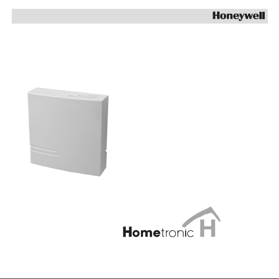
Shutter
Module
HA 30
Mounting and Operation
Page 2

Page 3

Contents
Contents
Overview 2
Mounting 3
1. Setting the limit switch of the tube motor 4
2. Laying cables 4
3. Connecting pushbuttons and motors 5
Teach-in 8
1. Activating the teach-in mode at the shutter module 8
2. Activating the Teach-in mode at the Hometronic Manager 9
3. Determining the end position 11
Setting the 50% position (optional) 11
Failed teach-in 12
Final mounting 13
Operation 15
Controlling the shutters with pushbuttons 15
Controlling the shutters with switches 15
Lock-out unit HAC 30 16
Changing the fuse of the shutter module 17
Information for the fitter 18
Technical data 19
Help with problems 20
1
Page 4

Overview
Overview
Application
The shutter module HA 30 is a component of the Hometronic System
and controls the tube motors of shutters, venetian blinds and awnings.
The shutter module can be operated either via the Hometronic
Manager or directly via the pushbutton.
The lock-out unit HAC 30 ensures that you cannot lock yourself out.
Extension by the Sun Module HB 05/15
The installation of the Hometronic Sun Module HB 05 or HB 15 allows
the control of the shutter position depending on ...
• Brightness (Sun Module HB 05).
• Brightness and wind speed (Sun Module HB 15).
Danger of injury!
Caution!
2
For security reasons automatic control of awnings on
the basis of the wind speed is only allowed with the
wind sensor HWS 40!
Page 5
Mounting
Danger!
Caution!
Mounting
Danger to life through electric shock!
Live electrical contacts lie open while the module is
being cabled. Touching a live contact causes critical
injuries.
► All work may only be carried out by authorized
specialized personnel.
► De-energize the corresponding fuse during all work on
the module.
Faulty radio connection!
The shutter module has a radio transmitter whose
function can be impaired by metallic objects.
► When selecting the operation site ensure that there is
sufficient distance to metallic objects such as metal
cabinets and doors, concrete ceilings with iron lattices
at radio devices such as radio headphones, etc.
3
Page 6
Mounting
1. Setting the limit switch of the tube motor
► If the tube motor of the shutter has a limit switch, set the limit switch
before connecting the shutter module.
2. Laying cables
The device switch is intended to be mounted on a flush-mounted
distribution box.
► Cut the cables to length or lengthen them so that they reach at least
10 cm out of the distribution box.
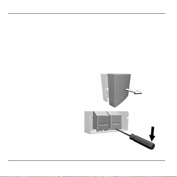
► Remove the housing cover
from the module.
► Leverout the contact covers
with a screwdriver.
► Insert all the cables through the openings in the housing bottom.
4
Page 7
Mounting
► Mount the lock-out unit HAC 30 as described in the enclosed
mounting instructions (please also refer to Page 16).
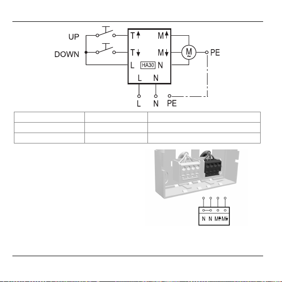
3. Connecting pushbuttons and motors
You can connect either pushbuttons or switches to the
device switch. Use pushbuttons for a new installation.
Malfunctions due to contact erosion
Caution!
The following figure shows the circuiting for connecting pushbuttons/switches and tube motors. The designations of the
connections are also used in the further description of the mounting.
► Replace old pushbuttons/switches by new push-
buttons.
► Only use pushbuttons which are designed for 230 V
and conform to the VDE guidelines.
5
Page 8
Mounting
T↑: "Up“ button M↑: Motor UP L: Phase
T↓: "Down" button M↓: Motor DOWN N: Neutral conductor
M: Motor PE: Protective earth conductor
► Connect the tube motor at the
right-hand terminal block in
accordance with the diagram.
► Loop the PE conductor through the flush-mounted box to the motor.
6
Page 9

Mounting
► Connect the pushbuttons/
switches "Up" (T↑) and
"Down" (T↓) to the left-hand
terminal block in accordance with the diagram.
No terminal is planned for the protective earth conductor.
► Fasten the housing base temporarily at the intended mounting site
so that smaller corrections can be carried out later if required.
► Slide the housing cover onto
the housing base and latch
it in.
7
Page 10

Teach-in
Teach-in
The new Hometronic components have to be assigned to the
Hometronic Manager first before they can be taken into operation.
This process is called the "Teach-in". During the process the
Hometronic Manager and the new components exchange data.
The teach-in mode remains active for a maximum of 4
minutes. Afterwards the shutter module changes back to
normal mode. Therefore familiarize yourself with the following
steps beforehand.
1. Activating the teach-in mode at the shutter module
► Use the "Up" button to open the shutter completely.
► Within 10 seconds press the "Down" button briefly exactly 5 times.
Ensure that the motor moves after each pressing action. The
shutter module does not recognize if the pressing action is too
fast or too brief.
As confirmation the shutter travels downwards for 2 seconds. The
teach-in mode at the shutter module is activated.
8
Page 11

Teach-in
2. Activating the teach-in mode at the Hometronic
Manager
The yellow LED at the Hometronic Manager lights up.
The display shows the standard
display, for example:
► Press the Dial button at the
Hometronic Manager.
The cursor flashes in the bottom line.
► Turn the Dial button to the right in
order to move the cursor to the
highest line.
► Press the Dial button.
The following text is displayed:
► Select "Settings" and press the Dial
button twice.
The following text is displayed:
Hometronic
WE 29.10.1999 11:15
No Lifestyle active
LIVING 20.0 C
MENU
SET DATE/TIME
ACTIVATE LIFESTYLE
LIVING 20.0 C
MENU
SET DATE/TIME
ACTIVATE LIFESTYLE
LIVING 20.0 C
LIFESTYLES
TIME PROGRAMS
DISPLAY
SETTINGS
HEATING
SHUTTERS
DEVICES/LIGHT
SENSOR
9
Page 12

Teach-in
► Turn the Dial button to the left in order
to select the "Shutters" submenu.
HEATING
SHUTTERS
DEVICES/LIGHT
SENSOR
► Press the Dial button.
The following text is displayed:
MODULE-1
MODULE-2
MODULE-3
MODULE-4
► Select the module to be installed, in
this case Module 2.
MODULE-1
MODULE-2
MODULE-3
MODULE-4
► Press the Dial button in order to
activate the teach-in mode.
A I✝is displayed next to the selected
module (in this case Module 2).
MODULE-1
MODULE-2 *
MODULE-3
MODULE-4
The Hometronic Manager is ready for data transfer.
The teach-in mode is active.
The teach-in was successful, if the shutter travels completely
upwards.
10
Page 13

Teach-in
3. Determining the end position
If it is not possible to travel to end positions or a button action
is interrupted, the teach-in has to be repeated.
► Keep the "Down" pushbutton/switch pressed until the shutter
reaches the lower end position and the drive stops.
► Keep the "Up" pushbutton/switch pressed until the shutter reaches
the upper end position and the drive stops.
The teach-in mode is terminated.
Setting the 50% position (optional)
The shutter module can determine half the opening width of a shutter
exactly. The Hometronic Manager can thus open and close the shutter
with greater precision.
► Press the "Up" button until the shutter is opened completely.
► Within 10 seconds press the "Up" button briefly exactly 5 times.
► Press the "Down" button until the shutter has reached the 50%
position.
The shutter module takes over the current position as the 50%
position. As confirmation the shutter opens the shutter completely.
11
Page 14

Teach-in
Failed teach-in
The teach-in has failed if the shutter travels downwards for some
seconds after 4 minutes.
► Carry out the following measures:
– Improve the transmission.
– Repeat the teach-in.
Improving the transmission
► Remove the disturbing/shielding devices, e.g.:
– Wireless headphones, loudspeakers, garage door openers or
remote control units
– Disturbing objects from the immediate environment
– Metal parts
► Correct the position of the shutter module at the mounting site.
12
Page 15

Final mounting
Final mounting
► Remove the housing cover
again.
► Clamp the contact covers in
the housing bottom.
► Screw the housing bottom onto the flush-mounted box or to the wall
in accordance with the drilling scheme.
13
Page 16

Final mounting
62
65
► Slide the housing cover onto the
housing base and latch it in.
Mounting has been completed.
14
68
Page 17

Operation
Operation
Controlling the shutters with pushbuttons
Use the "Up" and "Down" buttons to open or close the shutters
manually. One of the following functions is triggered depending on
how long the button is pressed:
Button pressed Function
► Less than 2 sec.
► Long
Controlling the shutters with switches
A switch with zero position is recognized by the
shutter module if a contact is activated longer
than 5 seconds. The shutter stops in the zero
position.
• Shutter travels up/down as long as the
button is pressed
• Shutter travels up/down until the end
position has been reached
• Shutter stops when any button is
pressed again
15
Page 18

Operation
Lock-out unit HAC 30
The lock-out unit prevents unwanted closing of a shutter, for example
when a terrace door is open, while you are outside the house.
If the door which is protected by the lock-out unit is open, every close
command at the Hometronic Manager and local pushbuttons/switches
is ignored.
16
Page 19

Changing the fuse of the shutter module
Danger to life through electric shock!
Danger!
► Remove the housing cover.
► Remove the defective fuse
(see figure).
► Insert a new fuse
(ceramic tube, 250 V,
5 x 20 mm, 2 A, fast).
► Replace the housing cover and latch it in.
Live electrical contacts are exposed when the contact
covers are opened. Touching a live contact causes
critical injuries.
► De-energize the corresponding circuit.
► Ensure that the contact covers are closed.
Operation
17
Page 20

Information for the fitter
Information for the fitter
After mounting and starting up has been completed, the Hometronic
System can be handed over to the customer.
► Familiarize your customer with the basic operation of the Hometronic
Manager.
► Explain the operation of the components on site.
► Also explain the possibilities offered by manual operation of the
components.
► If appropriate, point out the particular features and possibilities
offered by extending the respective installation of the Hometronic
System.
18
Page 21

Technical data
Power consumption shutter
motor
Operating voltage 230 V AC
Operating temperature 0...40 °C
Storage temperature -20...70 °C
Protection class IP 30
Maximum humidity 95%, non-condensing
Maximum 300 VA
Technical data
19
Page 22

Help with problems
Help with problems
Problem/Display Cause Remedy
Teach-in failed
Shutter is not positioned correctly
Shutter does not
react to operation
20
Radio connection faulty
Old pushbutton
("bouncing")
Brief power
failure / interruption of the
power voltage
Shut-out unit
activated
Fuse defective
Radio connection to Hometronic Manager
faulty
► Refer to "Improving
transmission"
► Remove the lock-out unit
as a test
► Repeat the teach-in
► Travel the shutter up and
down completely
► Close protected doors
and windows
► Check the mounting of
the shut-out unit
► Change the fuse
► Refer to "Improving
transmission"
Page 23

Page 24

Honeywell AG
Böblinger Straße 17
D – 71101 Schönaich
Telephone (+49) 7031 637-300
This company is certificated to
The right is reserved to make modifications. This document is definitive for the
enclosed product and replaces all previous publications.
No. 7157518 EN1H-0123 GE51 R0301
 Loading...