

Page 1
Place Bar Code Here
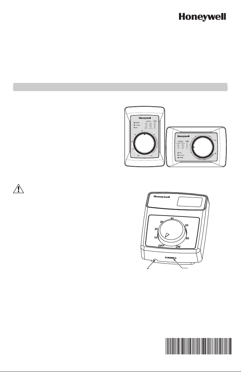
H8908A/B Humidistat;
CAUTION
H8908C/D Dehumidistat
INSTALLATION INSTRUCTIONS
APPLICATION
The H8908 family of low-voltage humidistats/
dehumidistats provide accurate control of whole house
humidifiers, dehumidifiers, and ventilators. They have a
snap-acting, dust-proof SPST switch and can be
mounted to a duct or wall.
Before Installing this Product...
1. Read these instructions carefully. Failure to follow
them could damage the product or cause a hazardous condition.
2. Check the ratings given in the instructions and on
the product to make sure the product is suitable for
your application.
3. Installer must be a trained, experienced service
technician.
Fig. 1. H8908A,D control.
M24726
Personal Injury Hazard.
Power supply can cause electrical shock.
Disconnect power supply before beginning
installation.
NOTE: The H8908 electrical connections are not
shared with the thermostat.
OUTDOOR
TEMPERATURE
-20 F
-30 C
-10 F
Humidity Control
Régulateur d'humidité
HOLE FOR WIRING
THE DUCT MOUNTING
INSTALLATIONS
0 F
+10 F
+20 F
Over 20 F
Over 0 C
CASE REMOVAL
SLOT
-25 C
-20 C
-10 C
-5 C
Fig. 2. H8908B,C control.
HUMIDITY
SETTING
15%
20%
25%
30%
35%
40%
M13371
69-1341EF-07
Page 2
H8908A/B HUMIDISTAT; H8908C/D DEHUMIDISTAT
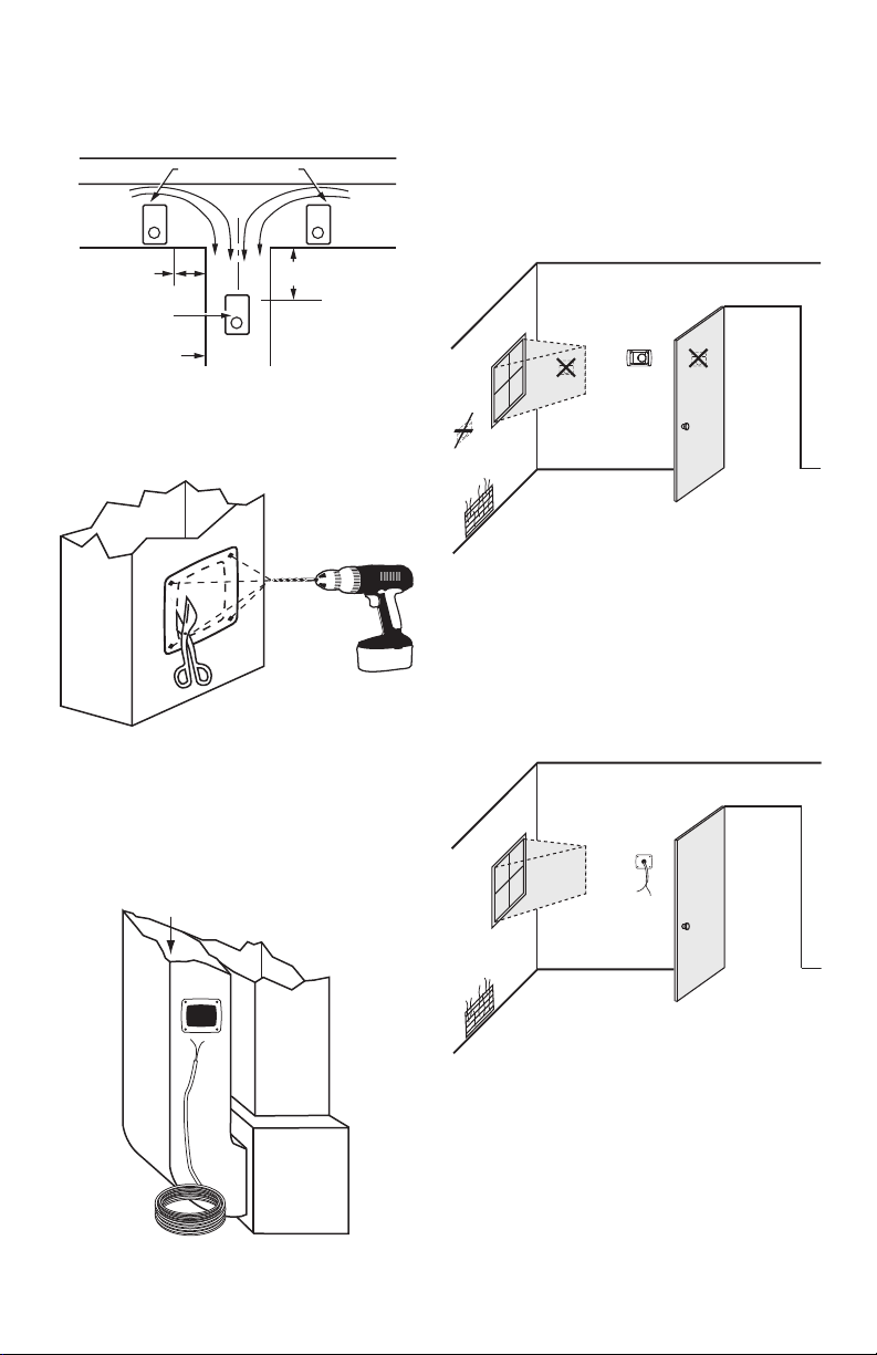
DUCT INSTALLATION
1. Choose a location on the duct.
ALTERNATE LOCATION
RETURN
AIR
6 in. (152 mm)
MINIMUM
BEST
LOCATION
RETURN AIR DUCT
15 in. (381 mm)
MINIMUM
Fig. 3. Duct installation locations.
2. Apply sticker template to duct and drill holes for
mounting screws. Cut along the dotted line of the
template with metal shears or tin snips.
Fig. 4. Drill and cut holes in duct.
3. Run two-fan, low-voltage wire to the mounting loca-
tion on the duct. See Fig. 5.
IMPORTANT
Use rated 18-22 gauge wire. Leave approximately
6 in. of wire to properly connect the humidistat.
RETURN
AIR
M13369
M24800
REMOTE MOUNT
INSTALLATION
1. Choose a location in the living area.
NOTE: Select a location clear of drafts or excessive
humidity. Avoid mounting near doors or windows, or in bathrooms or kitchens. See Fig. 6.
Fig. 6. Choose a location in the living area.
2. Cut 1 in. diameter wire hole in wall.
3. Run two-fan, low-voltage wire to the mounting loca-
tion in the living area.
IMPORTANT
Use rated 18-22 gauge wire. Leave approximately 6 in. of wire to properly connect the humidistat.
M24718
RETURN
SUPPLY
TWO-FAN 18-22 GAUGE WIRE
M24720
Fig. 5. Run wire to the mounting location.
69-1341EF—07 2
M24721
Fig. 7. Run wire to the mounting location.
Page 3
H8908A/B HUMIDISTAT; H8908C/D DEHUMIDISTAT
M24722
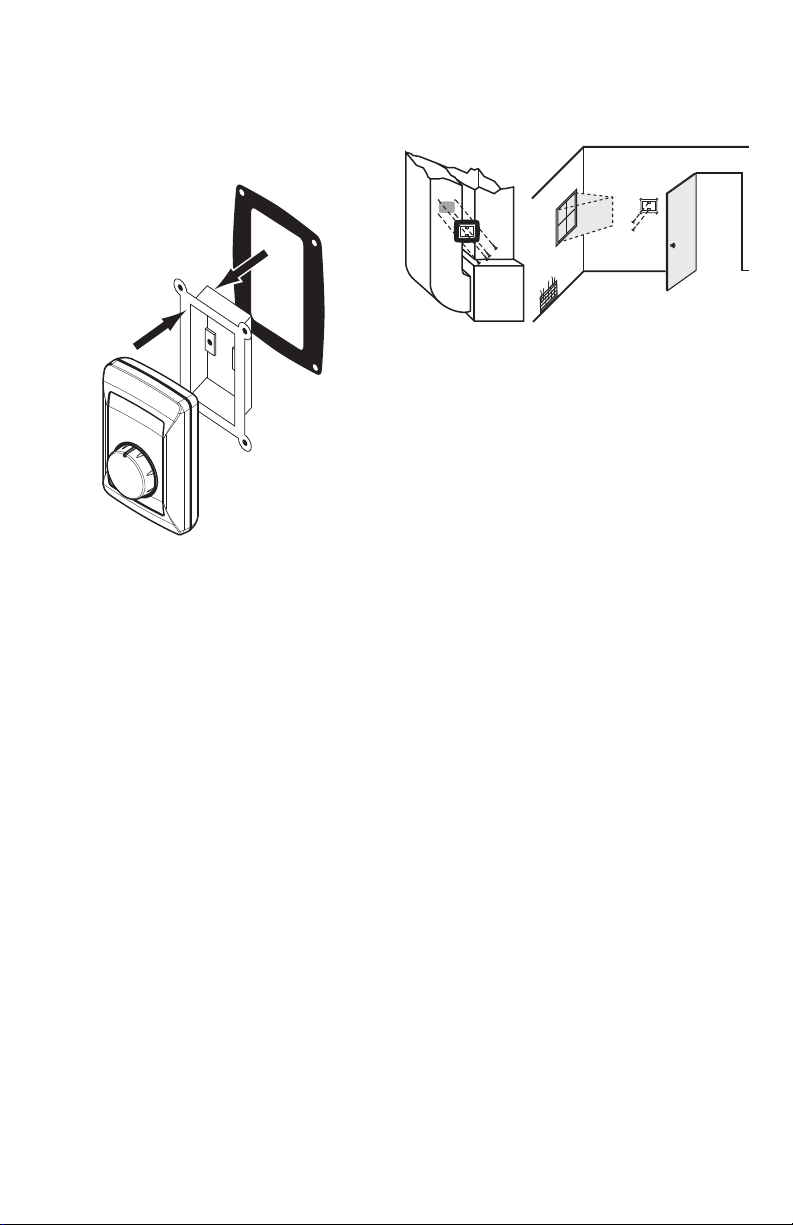
4. Remove the base bracket from the humidistat. For
duct mount, slide the black gasket onto the base
bracket. See Fig. 8.
NOTE: Use gasket only when mounting the control to
ductwork. Leave off when mounting to a wall.
M24733
Fig. 8. Seal base bracket.
5. Secure the base bracket to the duct or remote loca-
tion. Secure to the duct with four 1-in. (25 mm)
screws (provided) or to the wall with two 1-in. (25
mm) screws (provided).
Fig. 9. Mount base bracket to duct or remote location.
3 69-1341EF—07
Page 4
H8908A/B HUMIDISTAT; H8908C/D DEHUMIDISTAT
CAUTION
WIRING
Personal Injury Hazard.
Can cause electrical shock and injury.
Disconnect power before installation or servicing.
All wiring must comply with applicable local codes,
ordinances and regulations. Make wiring connections
according to humidifier (or dehumidifier/ventilator)
instructions, if available; otherwise, see typical wiring
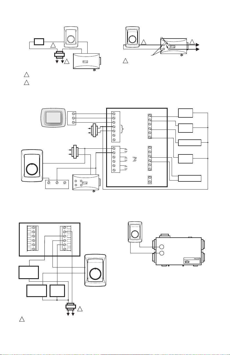
diagrams in Fig. 12–19.
IMPORTANT
Select models of fan centers include humidifier
taps so the current sensing relay, sail switch or
air pressure switch is not needed. If not using a
current sensing relay, sail switch, or air pressure
switch, the humidifier must be energized during
blower motor cycles for proper operation.
On multispeed blower applications, do not wire
the high voltage side of the transformer to the
same power source that services the furnace
blower. Premature transformer burnout can
occur. On HE365 fan powered humidifier models, only the two yellow wires are connected to
the control. The remaining two red wires are only
used with electronic humidity controls.
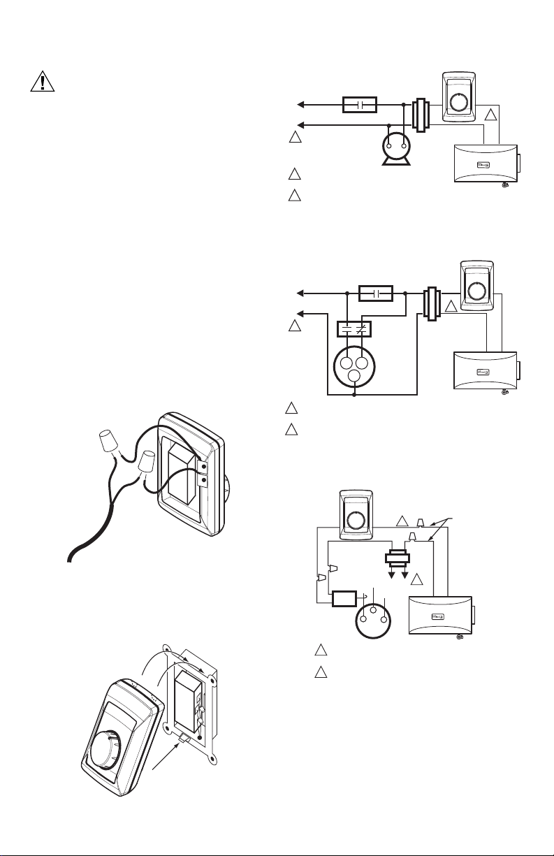
6. Using wire nuts, connect the low-voltage wire to the
leads on the H8908 humidistat. See Fig. 6–19 for
different wiring configurations.
H8908
30 40
TRANSFORMER
20
10
OFF ON
HUMIDIFIER
L1
POWER
(HOT)
L2
1
12PROVIDE DISCONNECT MEANS AND
FAN CONTROL
SUPPLY
FURNACE
FAN
MOTOR
OVERLOAD PROTECTION AS REQUIRED.
24 VAC WIRING.
Fig. 12. Wiring H8908 with fan interlock.
L1
POWER
(HOT)
SUPPLY
L2
1
POWER SUPPLY. PROVIDE DISCONNECT MEANS
1
AND OVERLOAD PROTECTION AS REQUIRED.
2
24 VAC WIRING.
FAN CONTROL
HL
C
DPST
SWITCHING
RELAY
2-SPEED
FAN
MOTOR
2
TRANSFORMER
Fig. 13. Wiring H8908 with 2-speed fan motor.
50
60
H8908
30 40
20
10
OFF ON
HUMIDIFIER
M24728
2
M24727
50
60
M24734
Fig. 10. Wire the humidistat.
7. Mount the humidistat by hooking the two hinges at
the top of the back cover to the raised edge at the
top of the base bracket. Press the bottom of the
humidistat in to engage the base hinge. You will
hear a “click” when the humidistat is secured.
M24801
Fig. 11. Attach the humidistat to the base.
69-1341EF—07 4
H8908
30 40
50
20
10
OFF ON
TRANSFORMER
CURRENT
SENSING
RELAY
1
POWER SUPPLY. PROVIDE DISCONNECT MEANS
AND OVERLOAD PROTECTION AS REQUIRED.
2
24V WIRING.
Fig. 14. Typical wiring diagram of current
sensing relay with humidifier.
2
60
L1
L2
(HOT)
LO
C
HI
1
HUMIDIFIER
WATER
SOLENOID
LEAD WIRE
M24729
Page 5
H8908A/B HUMIDISTAT; H8908C/D DEHUMIDISTAT
H8908
AIR
PRESSURE SWITCH/
SAIL SWITCH
2
40
30
50
20
10
60
OFF ON
TRANSFORMER
1
L1
L2
(HOT)
1
POWER SUPPLY. PROVIDE DISCONNECT MEANS
AND OVERLOAD PROTECTION AS REQUIRED.
2
24V WIRING.
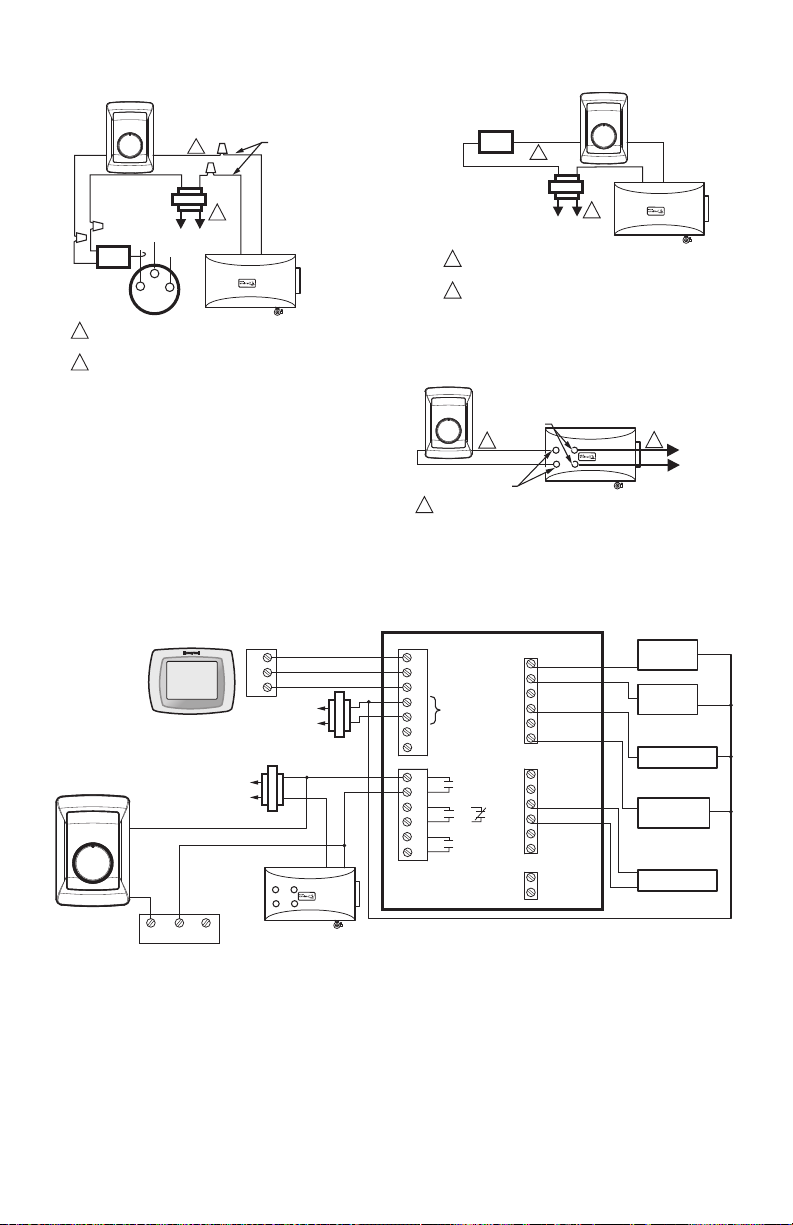
Fig. 15. Wiring H8908 in line with
air pressure switch/sail switch and humidifier.
TH9421 VISION PRO
THERMOSTAT
H8908B
30 40
20
10
OFF ON
50
60
24 VOLT
TRANSFORMER
HUMIDIFIER
1
2
3
SYSTEM
TRANSFORMER
L2
C
L1
R
M24730B
L2
L1
C
R
COM N.O. N.C.
S688 AIR
PRESSURE
SWITCH/
SAIL SWITCH
HE225/HE265
HUMIDIFIER
Fig. 17. Wiring H8908 with VisionPRO® IAQ on typical 2-stage furnace.
VISIONPRO® THERMOSTAT
Y2
L
A
W2
S1
S2
RC
R
W
Y
G
C
H8908D
H8908
FAN WIRING
30 40
TERMINALS
50
20
10
60
1
OFF ON
HUMIDISTAT
TERMINALS
24V WIRING.
1
FOLLOW THE INSTALLATION INSTRUCTIONS
NOTE:
INCLUDED WITH THE STEAM HUMIDIFIER
TO WIRE THE SYSTEM FAN.
HUMIDIFIER
Fig. 16. Wiring H8908 with steam humidifiers.
EQUIPMENT INTERFACE MODULE
1
2
3
C
24 VAC
R
RC
RH
H1
U
M2
D1
H
OR
M2
V1
N
T2
H8908D
20
10
30 40
OFF ON
50
60
CONV. HP
W1
W2
W3
Y
Y2
G
L
NOT USED
OUT1
OUT2
IN1
IN2
DATS1
DATS2
STAGE 1
O/B
AUX
AUX2
Y
Y2
G
HEAT
STAGE 2
HEAT
COMPRESSOR
FAN
RELAY
C7089U1006
VENTILATOR/DEHUMIDIFIER
TERMINALS
1
TO
SYSTEM
FAN
M24731
M24724B
HEATING
RELAY OR
VALVE COIL
COOLING
CONTACTOR
COIL
FAN
RELAY
COIL
1
PROVIDE OVERLOAD PROTECTION
1
AND DISCONNECT MEANS AS REQUIRED.
Fig. 18. Wiring H8908 with VisionPRO®
Thermostat for dehumidification.
20
10
30 40
OFF ON
M24725
Fresh Air Ventilation System
Système de ventilation à air frais
50
60
Fig. 19. Typical wiring diagram for HR150,
HR200, ER150 and ER200 Ventilator
or DH90 Dehumidifier applications.
M24732
5 69-1341EF—07
Page 6

H8908A/B HUMIDISTAT; H8908C/D DEHUMIDISTAT
CHECKOUT
Turn the H8908 dial to “ON” to test proper installation.
See Fig. 20.
You will hear an audible click if installed correctly, and
water will begin flowing to the humidifier.
OUTDOO
R
HUMID
ITY
TEMP
ERATURE
SET
TING
-20 F
-30 C
15%
-10 F
-25 C
Humidity Control
Régulateur d'humidité
Fig. 20. Turn humidistat on.
20%
0 F
-20 C
25%
+10 F
-10 C
30%
+20 F
-5 C
35%
Over
20 F
Over
0 C
40%
M24723
OPERATION
Humidity Control Adjustment
To maintain optimal humidity levels without causing
condensation on cold surfaces such as windows, the
homeowner must adjust the setpoint as the outdoor
temperature changes.
To reduce the relative humidity, lower the setpoint
approximately three percent relative humidity every 24
hours. To increase the relative humidity, increase the
setpoint approximately three percent relative humidity
every 24 hours.
Setpoint Adjustment
Set the humidity setpoint according to the prevailing
outdoor temperature. Recommended settings are
available on the control and in the table below.
Table 1. Recommended Humidity
Controller Settings.
Outdoor Temperature
-20 -29 15
-10 -23 20
0-18 25
+10 -12 30
+20 -7 35
>+20 >-7 40
Outdoor Temperature
+70 +21 50
+75 +24 40
+80 +27 35
+85 +29 30
+90 +32 25
>+100 >+38 20
Recommended
H8908A,B Setpoints°F °C
Recommended
H8908C,D Setpoints°F °C
69-1341EF—07 6
Page 7

H8908A/B HUMIDISTAT; H8908C/D DEHUMIDISTAT
7 69-1341EF—07
Page 8

H8908A/B HUMIDISTAT; H8908C/D DEHUMIDISTAT
Automation and Control Solutions
Honeywell International Inc.
1985 Douglas Drive North
Golden Valley, MN 55422
Honeywell Limited-Honeywell Limitée
35 Dynamic Drive
Toronto, Ontario M1V 4Z9
customer.honeywell.com
® U.S. Registered Trademark
© 2010 Honeywell International Inc.
69-1341EF—07 T.D. Rev. 11-10
Printed in U.S.A.
Page 9

Place Bar Code Here
Humidistat H8908A/B
MISE EN GARDE
Déshumidistat H8908C/D
NOTICE D'INSTALLATION
APPLICATION
Les humidistats et les déshumidistats basse tension de
la gamme H8908 assurent la régulation précise de
l'humidification, la déshumidification et la ventilation dans
toute la maison. Ils fonctionnent au moyen d'un
interrupteur unipolaire unidirectionnel à rupture brusque,
à l'épreuve de la poussière. Ils peuvent être installés sur
une gaine ou sur un mur.
AVANT D'INSTALLER CET
APPAREIL…
1. Lire attentivement les présentes instructions. Le
fait de ne pas les suivre risque d'endommager le
produit ou de constituer un danger.
2. Vérifier les caractéristiques spécifiées dans les
instructions et indiquées sur le produit, et s'assurer
que celui-ci correspond à l'application prévue.
3. L'installateur doit être un technicien d'expérience
ayant reçu une formation pertinente.
Risque de blessure.
Peut donner un choc électrique.
Couper l'alimentation avant de procéder à
l'installation.
REMARQUE : Les connexions du H8908 et du
thermostat ne sont pas communes.
Fig. 1. Régulateur H8908 A et D.
Humidity Control
Régulateur d'humidité
M24726
OUTDOOR
HUMIDITY
TEMPERATURE
SETTING
-20 F
-30 C
15%
-10 F
-25 C
20%
0 F
-20 C
25%
+10 F
-10 C
30%
+20 F
-5 C
35%
Over 20 F
Over 0 C
40%
ORIFICE POUR LE
CÂBLAGE DANS LES
INSTALLATIONS SUR GAINE
FENTE DE DÉGAGEMENT
DU BOÎTIER
Fig. 2. Régulateur H8908 B et C.
MF13371
69-1341EF-07
Page 10

HUMIDISTAT H8908A/B DÉSHUMIDISTAT H8908C/D
INSTALLATION SUR UNE GAINE
1. Choisir l'emplacement sur la gaine.
EMPLACEMENTS POSSIBLES
RETOUR
D’AIR
MAXIMUM
152 mm (6 po)
EMPLACEMENT
PRÉFÉRABLE
GAINE DE
Fig. 3. Emplacements possibles pour installation sur
RETOUR D’AIR
une gaine.
2. Coller le gabarit sur la gaine à l'emplacement
choisi. Percer les trous pour les vis de montage. À
l'aide de cisailles à métal, découper la tôle en suivant la ligne pointillée.
MINIMUM
381 mm (15 po)
Fig. 4. Percer les trous et découper la gaine.
3. Amener un fil double basse tension pour ventilateur
jusqu'à l'emplacement de montage sur la gaine.
Voir la Fig. 5.
IMPORTANT
Utiliser du fil de calibre 18 à 22. Prévoir une
quinzaine de centimètres (6 po) de fil pour
effectuer le raccordement de l'humidistat.
RETOUR
RETOUR
D’AIR
MF13369A
M24800
MONTAGE À DISTANCE DANS
UNE PIÈCE
1. Choisir l'emplacement de montage dans la pièce.
REMARQUE : Choisir un emplacement à l'abri des cou-
2. Découper un trou de 2,5 cm (1 po) pour passer le fil
3. Amener un fil double basse tension pour ventilateur
IMPORTANT
rants d'air et de l'humidité excessive. Ne
pas installer l'appareil près des portes ou
des fenêtres ni dans la salle de bain ou la
cuisine. Voir la figure 6.
M24718
Fig. 6. Choisir l'emplacement dans la pièce.
dans le mur.
jusqu'à l'emplacement de montage dans la pièce.
Voir la Fig. 5.
Utiliser du fil de calibre 18 à 22. Prévoir une
quinzaine de centimètres (6 po) de fil pour
effectuer le raccordement de l'humidistat.
ALIMENTATION
D’AIR
FIL DOUBLE POUR VENTILATEUR
DE CALIBRE 18 À 22
MF24720
Fig. 5. Amener le fil jusqu'à l'emplacement de montage.
69-1341EF—07 2
Fig. 7. Amener le fil jusqu'à l'emplacement de
montage.
M24721
Page 11

HUMIDISTAT H8908A/B DÉSHUMIDISTAT H8908C/D
M24722
4. Retirer la plaque de montage de l'humidistat. Dans
le cas d'une installation sur une gaine, insérer la
garniture d'étanchéité sur la plaque de montage.
Voir la Fig. 8.
REMARQUE : Utiliser la garniture seulement pour une
installation sur une gaine. Ne pas l'utiliser
dans le cas d'une installation sur un mur.
M24733
Fig. 8. Poser la garniture d'étanchéité.
5. Poser la plaque de montage sur la gaine ou à
l'emplacement choisi dans la pièce. Fixer à la gaine
avec les quatre vis de 25 mm (1 po) fournies. Fixer
au mur avec les deux vis de 25 mm (1 po) fournies.
Fig. 9. Poser la plaque de montage sur la gaine ou sur
le mur.
3 69-1341EF—07
Page 12

HUMIDISTAT H8908A/B DÉSHUMIDISTAT H8908C/D
MISE EN GARDE
H8908
T
7
RACCORDEMENT
Risque de blessure
Peut causer des chocs électriques et des
blessures.
Débrancher toute source d'alimentation avant
d'installer ou de réparer.
Tout le câblage doit être conforme aux codes et aux
règlements locaux. Effectuer les raccordements en
suivant la notice technique de l'humidificateur, du
déshumidificateur ou du ventilateur si elle existe. Sinon,
consulter les schémas de raccordement aux figures Fig.
12–19.
IMPORTANT
Pour certains modèles de commandes de
ventilateur qui ont des connections pour un
humidificateur, le relais ampéremétrique,
interrupteur à ailette ou un pressostat d'air n'est
pas nécessaire. Si vous n'utilisez pas de relais
ampéremétrique, interrupteur à ailette ou
pressostat d'air, l'humidificateur doit être mis
sous tension en même temps que le ventilateur.
Dans les applications avec ventilateur à plusieurs
vitesses, ne pas raccorder le côté haute tension
du transformateur à la même source
d'alimentation que celle du ventilateur de
l'appareil de chauffage. Il pourrait en résulter un
grillage prématuré du transformateur. Avec les
humidificateurs HE365 avec ventilateur, ne
raccorder que les deux fils jaunes au régulateur.
Les deux fils rouges ne servent que dans le cas
de régulateurs d'humidité électroniques.
6. Utiliser des connecteurs de fils pour raccorder les
fils basse tension aux connecteurs de l'humidistat
H8908. Consulter les Fig. 6–19 pour connaître les
configurations possibles.
M24734
Fig. 10. Raccorder l'humidistat.
7. Pour monter l'humidistat, accrocher les deux
charnières au haut du couvercle arrière aux pattes
au haut de la plaque de montage. Appuyer sur le
bas de l'humidistat pour enclencher la charnière du
bas. Un clic se fait entendre lorsque l'humidistat est
bien en place.
M24801
Fig. 11. Fixer l'humidistat sur la plaque de montage.
COMMANDE DU
L1
(SOUS
ENSION)
L2
1
1
2
L1
(SOUS
TENSION)
ALIMENTATION
L2
1
1
ALIMENTATION. FOURNIR, AU BESOIN, UN DISPOSITIF DE
COUPURE ET UNE PROTECTION CONTRE LES SURCHARGES.
2
CÂBLAGE 24 V c.a.
Fig. 13. Raccordement du H8908 avec un moteur de
VENTILATEUR
ALIMENTATION
MOTEUR DU
VENTILATEUR DE
L’APPAREIL DE
CHAUFFAGE
FOURNIR, AU BESOIN, UN DISPOSITIF DE
COUPURE ET UNE PROTECTION CONTRELES
SURCHARGES.
CÂBLAGE 24 V c.a.
Fig. 12. Raccordement du H8908 avec
asservissement du ventilateur.
COMMANDE DU
VENTILATEUR
FAN CONTROL
HL
C
RELAIS
COMMUTATION
BIPOL. UNIDIR.
MOTEUR
VENTILATEUR
2 VITESSES
TRANSFORMATEUR
ventilateur à deux vitesses.
30 40
20
10
OFF ON
TRANSFORMATEUR
HUMIDIFICATEUR
H8908
30 40
20
10
OFF ON
2
HUMIDIFICATEUR
50
60
50
60
MF24728
2
MF2472
69-1341EF—07 4
Page 13
HUMIDISTAT H8908A/B DÉSHUMIDISTAT H8908C/D
MODULE D’INTERFACE DE L’ÉQUIPEMENT
H8908
30 40
50
20
10
OFF ON
2
60
TRANSFORMATEUR
L2
L1 (SOUS
TENSION)
RELAIS À
CAPTEUR DE
COURANT
1
2
Fig. 14. Schéma de raccordement typique d'un relais
à capteur de courant avec un humidificateur.
LO
C
HI
ALIMENTATION. FOURNIR, AU BESOIN, UN DISPOSITIF DE
COUPURE ET UNE PROTECTION CONTRE LES SURCHARGES.
CÂBLAGE 24 V c.a.
THERMOSTAT
VISION PRO TH9421
TRANSFORMATEUR 24 V
H8908B
30 40
50
20
10
60
OFF ON
FILS DU
SOLÉNOÏDE
DE L’EAU
1
HUMIDIFICATEUR
1
2
3
TRANSFORMATEUR
DU SYSTÈME
L2
L1
MF24729
L2
C
L1
R
C
R
H8908
PRESSOSTAT D'AIR/
INTERRUPTEUR À AILETTE
30 40
50
20
10
60
OFF ON
2
TRANSFORMATEUR
1
L1 (SOUS
L2
TENSION)
1
ALIMENTATION. FOURNIR, AU BESOIN, UN DISPOSITIF DE
COUPURE ET UNE PROTECTION CONTRE LES SURCHARGES.
2
CÂBLAGE 24 V c.a.
Fig. 15. Raccordement du H8908 en série avec
pressostat d'air/interrupteur à ailette et
humidificateur.
HUMIDIFICATEUR
MF24730B
H8908
30 40
BORNES DE RACCORDEMENT DU
50
20
VENTILATEUR
10
60
1
OFF ON
BORNES DE
L’HUMIDISTAT
CÂBLAGE 24 V c.a.
1
REMARQUE :
SUIVRE LES INSTRUCTIONS D’INSTALLATION
DE L’HUMIDIFICATEUR À VAPEUR POUR
RACCORDER LE VENTILATEUR DU SYSTÈME.
Fig. 16. Raccordement du H8908 avec un
1
2
3
C
24 V C.A.
R
RC
RH
H1
U
M2
D1
H
OU
M2
V1
N
T2
HUMIDIFICATEUR
humidificateur à vapeur.
CLA SSI Q U E THERMO-
POM PE
W1
O/B
W2
AUX
W3
AUX2
Y
Y
Y2
Y2
G
G
L
NON UTILISÉ
OUT1
OUT2
IN1
IN2
DATS1
DATS2
1
CHAU FFAGE
ÉTAGE 1
CHAU FFAGE
ÉTAGE 2
COM P RESSEU R
RELA I S DE
VENTILATEUR
C7089U1006
VERS LE
VENTILATEUR
DU SYSTÈME
MF24731
COM N.O. N.C.
PRESSOSTAT D'AIR/
IN TERRU PTE UR À AI LE TTE S688
HUMIDIFICATEUR
HE225/HE265
MF24724B
Fig. 17. Raccordement du H8908 avec un VisionPRO® IAQ sur un système de chauffage typique à deux étages.
5 69-1341EF—07
Page 14

HUMIDISTAT H8908A/B DÉSHUMIDISTAT H8908C/D
ET UNE PROTECTION CONTRE LES SURCHARGES.
THERMOSTAT VISIONPRO®
Y2
L
A
W2
S1
S2
RELAIS DE
CHAUFFAGE
OU BOBINE
DE LA VANNE
BOBINE DU
CONTACTEUR DE
REFROIDISSEMENT
BOBINE DU
RELAIS DU
VENTILATEUR
RC
R
W
Y
G
C
H8908D
30 40
50
20
60
10
OFF ON
1
FOURNIR, AU BESOIN, UN DISPOSITIF DE COUPURE
1
Fig. 18. Raccordement du H8908 avec un thermostat
VisionPRO® pour la déshumidification.
MF24725
H8908D
30 40
50
20
10
60
OFF ON
VENTILATEUR/DÉSHUMIDIFICATEUR
BORNES
Fresh Air Ventilation System
Système de ventilation à air frais
MF24732
Fig. 19. Schéma de raccordement typique dans des
applications de ventilation avec un HR150, HR200,
ER150 et ER200 ou de déshumidification avec un
DH90.
69-1341EF—07 6
Page 15

HUMIDISTAT H8908A/B DÉSHUMIDISTAT H8908C/D
VÉRIFICATION
Tourner le cadran du H8908 jusqu'à la position
« marche » pour vérifier le fonctionnement de
l'installation. Voir la Fig. 20.
Si l'installation est bien effectuée, un clic se fait entendre
et l'eau commence à circuler dans l'humidificateur.
OUTDOO
R
HUMID
ITY
TEMP
ERATURE
SET
TING
-20 F
-30 C
15%
-10 F
-25 C
Humidity Control
Régulateur d'humidité
Fig. 20. Tourner l'humidistat pour le mettre en
marche.
20%
0 F
-20 C
25%
+10 F
-10 C
30%
+20 F
-5 C
35%
Over
20 F
Over
0 C
40%
M24723
FONCTIONNEMENT
Réglage du régulateur d'humidité
Pour obtenir un niveau d'humidité optimal sans
condensation sur les surfaces froides comme les
fenêtres, il faut régler le point de consigne de l'humidité
en fonction de la température extérieure.
Pour diminuer le taux d'humidité relative, abaisser le point
de consigne d'environ trois pourcents d'humidité relative
aux 24 heures. Pour augmenter le taux d'humidité
relative, augmenter le point de consigne d'environ trois
pourcents d'humidité relative aux 24 heures.
Réglage du point de consigne
Régler le point de consigne d'humidité relative en tenant
compte de la température extérieure. Les réglages
recommandés sont indiqués sur le régulateur et dans le
tableau ci-dessous.
Tableau 1. Réglages d'humidité recommandés.
Température extérieure Point de consigne
-29 -20 15
-23 -10 20
-18 0 25
-12 +10 30
-7 +20 35
>-7 >+20 40
Température extérieure Point de consigne
+21 +70 50
+24 +75 40
+27 +80 35
+29 +85 30
+32 +90 25
>+38 >+100 20
recommandé -
H8908 A, B° C ° F
recommandé -
H8908 C, D° C ° F
7 69-1341EF—07
Page 16

HUMIDISTAT H8908A/B DÉSHUMIDISTAT H8908C/D
Solutions de régulation et d’automatisation
Honeywell International Inc.
1985 Douglas Drive North
Golden Valley, MN 55422
Honeywell Limited-Honeywell Limitée
35, Dynamic Drive
Toronto (Ontario) M1V 4Z9
customer.honeywell.com
® Marque de commerce déposée aux É.-U.
© 2010 Honeywell International Inc.
Tous droits réservés
69-1341EF—07 T.D. Rev. 11-10
Imprimé aux États-Unis
 Loading...