

Page 1

H46C,E Humidity Controllers
INSTALLATION INSTRUCTIONS
APPLICATION
The H46C,E Humidity Controllers are used with portable
and central unit dehumidifiers to maintain relative
humidity. The H46 has an spst, snap-acting switch
designed for line voltage circuits. The H46C has two
leadwires for switch box mounting. The H46E has an
electric cord with an interrupter plug.
INSTALLATION
When Installing this Product…
1. Read these instructions carefully. Failure to follow
them could damage the product or cause a hazardous condition.
2. Check the ratings given in the instructions and on
the product to make sure the product is suitable for
your application.
3. Installer must be a trained, experienced service
technician.
4. After installation is complete, check out product
operation as provided in these instructions.
CAUTION
Electrical Shock Hazard.
Can cause electrical shock or equipment
damage.
Disconnect power supply before connecting
wiring.
Location
Select a location about 5 ft (1.5 m) above the floor in an
area with good circulation at average temperature and
humidity for the area to be controlled. Avoid locations
near hot or cold air ducts and discharge air from the
controlled equipment.
Mounting H46C
1. Remove the setting knob.
2. Pull the cover forward from the device to remove.
3. Install a 2 in. x 3 in. (51 mm x 76 mm) vertical
switch box at the selected location.
4. Using the two screws provided, fasten the adapter
plate to the switch box as shown. See Fig. 1.
5. Pull the wires from the switch box through the
opening in the adapter plate and connect to the
H46 leadwires with the solderless connectors
(provided). See Fig. 4-6 for typical hookups.
6. Push the wires back into the switch box.
7. Place the H46 against the adapter plate, making
certain the tab at the bottom of the plate fits into the
notch on the H46.
8. Fasten the H46 to the adapter plate by tightening
the captive screw.
9. Replace the cover and the setting knob.
Mounting H46E
1. At the selected location, insert the two wood
screws (provided) into the wall 2 in. (51 mm)
vertically apart and protruding 1/16 in. (2 mm) from
the wall. See Fig. 2.
2. Position the H46 on the screws and slide it down
until the screws are in the slots.
3. Insert the dehumidifier plug into the end of the
interrupter plug. See Fig. 3.
4. Insert the interrupter plug into the electrical outlet.
NOTE: H46E has a 3-prong plug. When connecting to
the 2-prong receptacle, use the converter plug
(not included) and connect the pigtail lead to the
ground screw.
® U.S. Registered Trademark
Copyright © 2003 Honeywell International Inc. • • All Rights Reserved
69-1000B-1
Page 2

H46C,E HUMIDITY CONTROLLERS
2 X 3 IN.
S
F
(COVER ON)
P
S
PROTECTION AS REQUIRED.
H46C,E
R
N
R
ADAPTER PLATE
H46
(COVER OFF)
NYLON
ELEMENT
SCREWS (2)
H46 CAPTIVE
MOUNTING SCREW
SWITCH BOX
ADAPTER PLATE
PLATE TAB
H46 LEADWIRES (2)
WALL SURFACE
Fig. 1. Mounting H46C on vertical switch box.
WOOD SCREW
2 IN.
KEYHOLES
IN BACK O
CASE (2)
WALL
SURFACE
H46
CORD
M7908
Fig. 2. Mounting H46E with two screws.
M7907
STANDARD WALL OUTLET
OR EXTENSION CORD
TO H46E
H46E PLUG
DEHUMIDIFIER PLUG
TO DEHUMIDIFIER
M7909
Fig. 3. Connecting H46E interrupter plug.
WIRING
Disconnect power supply before connecting wiring to
avoid electrical shock or equipment damage. All wiring
must comply with local codes and ordinances. Do not
exceed contact and coil ratings when wiring into the
system.
Connections and Operation
A dehumidistat in combination with the thermostat can be
used to run the air conditioner to control relative humidity
levels. The H46C dehumidistat and thermostat can be
wired in parallel or in series.
Wiring in parallel allows the dehumidistat to independently control the humidity level, but could cause
overcooling of the home. During unoccupied times, the
homeowner should set the thermostat to a relatively high
setting and control moisture using the dehumidistat.
Wiring in series prevents overcooling but the air
conditioner runs only when both the thermostat and
dehumidistat are calling. During unoccupied times, the
homeowner should set the thermostat to a relatively low
setting and control moisture using the dehumidistat.
HUMIDITY
CONTROLLER
RISE
L1
(HOT)
OWER
1
UPPLY
L2
PROVIDE DISCONNECT MEANS AND OVERLOAD
1
DEHUMIDIFIE
EXHAUST FA
OR AIR
CONDITIONE
M7915
69-1000B-1 2
Fig. 4. Typical wiring diagram for H46C,E.
Page 3
H46C,E HUMIDITY CONTROLLERS
3
H46C
FILTER
LIGHT
HEAT OFF FANAUTO ONCOOL
3 2
1
PROVIDE OVERLOAD PROTECTION AND DISCONNECT MEANS
AS REQUIRED.
HEATING DAMPER MOTOR, IF USED.
2
3
CLOGGED FILTER SWITCH OR COOLING PANEL CONNECTION.
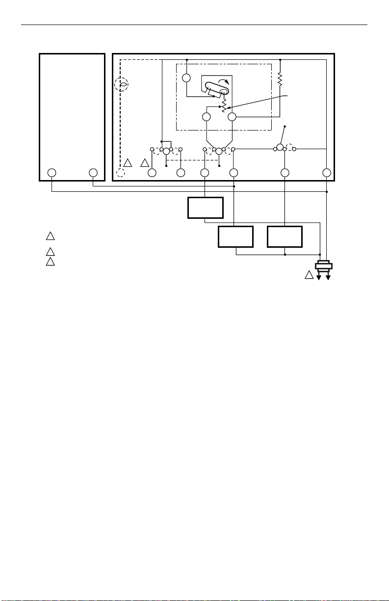
Fig. 5. Typical parallel wiring hookup for H46C with T87F/Q539A combination for dehumidification
T87F/Q539A INTERNALSCHEMATIC
R1
BX O
and mildew control.
T87F
TEMPERATURE
FALL
W1 Y1
HEAT OFF COOL
W Y
HEATING
RELAY OR
VALVE COIL
COOLING
CONTACTOR
COIL
FIXED
COOL
ANTICIPATOR
G RHR
FAN RELAY
COIL
ADJUSTABLE
HEAT
ANTICIPATOR
1
M791
3 69-1000B-1
Page 4

H46C,E HUMIDITY CONTROLLERS
M7914
H46C
T87F/Q539A INTERNALSCHEMATIC
T87F
FILTER
LIGHT
HEAT OFF FANAUTO ONCOOL
3 2
BXO
1
PROVIDE OVERLOAD PROTECTION AND DISCONNECT MEANS
AS REQUIRED.
HEATING DAMPER MOTOR, IF USED.
2
3
CLOGGED FILTER SWITCH OR COOLING PANEL CONNECTION.
Fig. 6. Typical series wiring hookup of H46C with T87F/Q539A combination for dehumidification
SETTINGS AND ADJUSTMENT
The H46 makes contact on a relative humidity rise to the
set point to start the dehumidifier. On a decrease in
relative humidity to the set point (minus the differential),
the switch breaks contact to stop the dehumidifier. Turn
the knob clockwise to the setting stop to place the H46 in
the ON position. Turn the knob counterclockwise to the
stop to place the H46 in the Off position.
R1
W1 Y1
HEAT OFF COOL
W Y
HEATING
RELAY OR
VALVE COIL
and mildew control.
CHECKOUT
After all mounting and wiring is completed, turn on the
power supply. Place the system into operation by turning
the setting knob toward the low end of the scale until the
dehumidifier motor starts. Turn the setting knob slowly
toward the high end of the scale until the dehumidifier
motor stops.
TEMPERATURE
FALL
COOLING
CONTACTOR
COIL
FIXED
COOL
ANTICIPATOR
G RHR
FAN RELAY
COIL
ADJUSTABLE
HEAT
ANTICIPATOR
1
Automation and Control Solutions
Honeywell International Inc. Honeywell Limited-Honeywell Limitée
1985 Douglas Drive North 35 Dynamic Drive
Golden Valley, MN 55422 Scarborough, Ontario
69-1000B-1 G.H. Rev. 7-03 www.honeywell.com/yourhome
M1V 4Z9
Printed in U.S.A. on recycled
paper containing at least 10%
post-consumer paper fibers.
Page 5

Hygrostats H46C,E
NOTICE D'INSTALLATION
APPLICATION
Les hygrostats H46C,E assurent la commande
automatique d’un déshumidificateur autonome ou central
et et à régler le taux d’humidité relative. L’hygrostat H46
est muni d’un interrupteur unipolaire, unidirectionnel, à
action rapide et est conçu pour les circuits tension
secteur. Le modèle H46 C comporte deux fils
conducteurs qui permettent le montage sur une boîte de
commutation. Le modèle H46 E comporte un cordon
d’alimentation et une fiche-prise.
INSTALLATION
Avant d’installer ce produit…
1. Lire les présentes directives attentivement. Le fait
de ne pas les suivre pourrait endommager le produit et constituer un danger.
2. Vérifier les caractéristiques nominales indiquées
dans les directives et inscrites sur le produit afin de
s’assurer que le produit convient à l’application
choisie.
3. L’installateur doit être un technicien expérimenté
ayant reçu la formation appropriée.
4. Une fois l’installation terminée, vérifier le fonctionnement de l’appareil en suivant les instructions cidessous.
MISE EN GARDE
Risque de choc électrique.
Peut causer des chocs électriques ou des
dommages matériels.
Couper l’alimentation avant d’effectuer le
raccordement.
Emplacement
Installer l’appareil à 1,5 m (5 po) du plancher dans un
endroit bien aéré, où il sera exposé à la température et à
l’humidité moyennes de la zone sous régulation. Placer
l’appareil loin des conduits d’air chaud ou d’air froid et de
la sortie d’air de l’appareil de régulation.
Montage du H46C
1. Enlever le bouton de réglage.
2. Tirer le couvercle vers l’avant pour l’enlever.
3. Installer une boîte de commutation verticale de 51
x 76 mm (2 x 3 po) à l’endroit choisi.
4. À l’aide des deux vis fournies, fixer la plaque
d’adaptation à la boîte de commutation. (Voir Fig.
1.)
5. Passer les fils de la boîte de commutation dans
l’ouverture de la plaque d’adaptation et raccorder
les fils conducteurs de l’hygrostat aux connecteurs
sans soudure fournis. (Voir Fig. 4, 5 et 6 pour le
raccordement type.)
6. Placer les fils conducteurs au fond de la boîte de
commutation.
7. Placer l’hygrostat sur la plaque d’adaptation de
manière que la languette de la plaque soit alignée
sur la rainure sur l’hygrostat.
8. Fixer l’hygrostat à la plaque d’adaptation à l’aide
de la vis imperdable.
9. Installer le couvercle et le bouton de réglage.
Montage du H46E
1. À l’endroit choisi, enfoncer dans le mur les deux vis
à bois fournies, à 51 mm (2 po) l’une au-dessus de
l’autre, en les laissant dépasser de 2 mm (1/16 po).
(Voir Fig. 2).
2. Placer l’hygrostat sur les vis et le glisser jusqu’à ce
que les vis entrent dans les fentes.
3. Insérer la fiche du déshumidificateur dans la ficheprise. (Voir Fig. 3.)
4. Insérer la fiche-prise dans la prise de courant.
NOTE: L’hygrostat H46E est muni d’une fiche à trois
broches. Pour le brancher sur une prise pour
fiche à deux broches, utiliser un adaptateur
(non fourni), et relier le fil conducteur en queue
de cochon à la vis de borne de terre.
® Marque de commerce déposée aux É.-U.
Copyright © 2003 Honeywell International Inc. • Tous droits réservés •
69-1000B-1
Page 6

HYGROSTATS H46C,E
BOÎTE DE
L
7
N
D'ALIMENTATION
HAUSSE
SURCHARGES.
5
HYGROSTAT
R
COMMUTATION
VIS DE PLAQUE
D'ADAPTATION (2)
VIS DE MONTAGE
IMPERDABLE H46
H46 (SANS
COUVERCLE)
ÉLÉMENT
DE DÉTECTION
EN NYLON
Fig. 1. Montage du H46C sur une boîte de
commutation verticale.
H46
(AVEC
COUVERCLE)
2 X 3 PO
PLAQUE D'ADAPTATION
LANGUETTE DE LA PLAQUE
FILS CONDUCTEURS DU H46
2 IN.
CORDON
MONTAGE MURA
VIS À BOIS
TROUS
DE FIXATIO
AU DOS DU
BOÎTIER (2)
MONTAGE
MURAL
MF7908
MF790
PRISE MURALE STANDARD OU
CORDON PROLONGATEUR
VERS LE H45E
FICHE-PRISE
DU H46E
FICHE DU DÉSHUMIDIFICATEUR
VERS LE DÉSHUMIDIFICATEUR
MF7909
Fig. 3. Branchement de la fiche-prise du H46E.
RACCORDEMENT
Couper l’alimentation avant de raccorder les fils afin
d’empêcher les chocs et les dommages à l’équipement.
Tout le câblage doit être conforme aux codes et
règlements locaux en matière d’électricité. S’assurer que
les charges n’excèdent pas les caractéristiques
nominales des contacts et des bobines indiquées.
Raccords et fonctionnement
Combiné à un thermostat, un déshumidistat peut servir à
faire fonctionner le système de refroidissement et à
régler le taux d’humidité relative. Le déshumidistat H46C
et le thermostat peuvent alors être raccordés en parallèle
ou en série. Le raccordement en parallèle permet de
faire fonctionner le déshumidistat de façon autonome
pour qu’il règle le taux d’humidité sans provoquer le
refroidissement exagéré de la maison. Pendant les
périodes d’inoccupation, le propriétaire devrait régler le
thermostat à un réglage relativement élevé et maîtriser
l’humidité en se servant du déshumidistat. Le
raccordement en série empêche le refroidissement
exagéré, mais le système de refroidissement fonctionne
seulement lorsque le thermostat et le déshumidistat le
demandent. Pendant les périodes d’inoccupation, le
propriétaire devrait régler le thermostat à un réglage
relativement bas pour arriver à maîtriser l’humidité en se
servant du déshumidistat.
Fig. 2. Montage du H46E au moyen des deux vis.
69-1000B-1 2
D'HUMIDITÉ
SOUS
TENSION
1
L2
ALIMENTATION. FOURNIR, AU BESOIN, UN DISPOSITIF
1
DE COUPURE ET UNE PROTECTION CONTRE LES
H46 C, E
VENTILATEUR
D'EXTRACTION
DU DÉSHUMIDIFICATEUR
OU CLIMATISEU
Fig. 4. Schéma de câblage type du H45C, E.
MF791
Page 7

SCHÉMA INTERNE DE Q539A T87F
H46C
HYGROSTATS H46C,E
T87F
VOYANT
DU FILTRE
CHAUFFAGE
3 2
1
FOURNIR, AU BESOIN, UN DISPOSITIF DE COUPURE ET
UNE PROTECTION CONTRE LES SURCHARGES.
MOTEUR DU REGISTRE DE CHAUFFAGE (LE CAS ÉCHÉANT).
2
3
INTERRUPTEUR DE FILTRE ENCRASSÉ OU CONNEXION
DU TABLEAU DE REFROIDISSEMENT.
Fig. 5. Schéma de câblage parallèle type du H46C et du T87F/Q539A pour assurer la déshumidification et
empêcher le développement de moisissure.
OFF
REFROIDISSEMENT
CHAUFFAGE
BXOR1W Y
BOBINE DE RELAIS
OU DE VANNE CHAUFFAGE
W1 Y1
OFF
BOBINE DU
CONTACTEUR REFROIDISSEMENT
BAISSE DE
TEMPÉRATURE
REFROIDISSEMENT
RÉSISTANCE
ANTICIPATRICE FIXE REFROIDISSEMENT
RÉSISTANCE
ANTICIPATRICE
RÉGLABLE CHAUFFAGE
FANAUTO ON
G RHR
BOBINE
DE RELAIS DU
VENTILATEUR
MF7913
1
3 69-1000B-1
Page 8

r
HYGROSTATS H46C,E
H46C
SCHÉMA INTERNE DE Q539A T87F
T87F
VOYANT
DU FILTRE
CHAUFFAGE
3 2
1
FOURNIR, AU BESOIN, UN DISPOSITIF DE COUPURE ET
UNE PROTECTION CONTRE LES SURCHARGES.
MOTEUR DU REGISTRE DE CHAUFFAGE (LE CAS ÉCHÉANT).
2
3
INTERRUPTEUR DE FILTRE ENCRASSÉ OU CONNEXION
DU TABLEAU DE REFROIDISSEMENT.
Fig. 6. Schéma de câblage en série type du H46C et du T87F/Q539A pour assurer la déshumidification et
empêcher le développement de moisissure.
RÉGLAGE
Les contacts du H46 se ferment sur une hausse
d’humidité relative pour mettre en marche le
déshumidificateur. Lorsque l’humidité relative revient au
point de consigne (moins le différentiel), les contacts
s’ouvrent pour arrêter le déshumidificateur. Tourner le
bouton de réglage dans le sens horaire jusqu’au point
d’arrêt pour mettre le H46 à la position ON. Tourner le
bouton de réglage dans le sens antihoraire jusqu’au
point d’arrêt pour mettre le H46 à la position Off.
OFF
REFROIDISSEMENT
CHAUFFAGE
BXOR1W Y
BOBINE DE RELAIS
OU DE VANNE CHAUFFAGE
VÉRIFICATION
Une fois le montage et le raccordement terminés, mettre
l’hygrostat sous tension. Tourner lentement le bouton de
réglage vers l’extrémité inférieure de l’échelle jusqu’à ce
que le moteur du déshumidificateur se mette en marche.
Tourner lentement le bouton de réglage vers l’extrémité
supérieure de l’échelle jusqu’à ce que le moteur du
déshumidificateur s’arrête.
W1 Y1
OFF
BOBINE DU
CONTACTEUR REFROIDISSEMENT
BAISSE DE
TEMPÉRATURE
REFROIDISSEMENT
RÉSISTANCE
ANTICIPATRICE FIXE REFROIDISSEMENT
RÉSISTANCE
ANTICIPATRICE
RÉGLABLE CHAUFFAGE
FANAUTO ON
G RHR
BOBINE
DE RELAIS DU
VENTILATEUR
MF7914
1
Solutions de régulation et d'automatisation
Honeywell International Inc. Honeywell Limited-Honeywell Limitée
1985 Douglas Drive North 35, Dynamic Drive
Golden Valley, MN 55422 Scarborough (Ontario)
69-1000B-1 G.H. Rév. 7-03 www.honeywell.com/yourhome
M1V 4Z9
Imprimé aux États-Unis sur du papie
recyclé contenant au moins 10 %
de fibres post-consommation.
 Loading...