

Honeywell GENT VSINTM-PCB-UPG Installation Manual
Installation
by Honeywell
PB2
S+ Z+ Z-S-
SECTOR/ ZONE1
PB3
S+ Z+ Z-S-
SECTOR/ ZONE2
PB4
S+ Z+ Z-S-
SECTOR/ ZONE3
PB5
S+ Z+ Z-S-
SECTOR/ ZONE4
PB1
0C LC 01
L102L2
LOOP
LN
PB6
++--
AUXO/P
P3
FS6
T3.16A
CERAMIC
ANTI-SURGE
SW1-POWERUP
P7
Mains Powered
Interface Unit Mk 3
P1
DANGER
DO NOT
REMOVE
FS8 F3.16A
QUICK
BLOW
ProductNo. 34440 REV 2
NominalVoltage rating 230VAC
RatedFrequency 50-60Hz
RatedCurrent 0.7A
Manufacture Date XX/XX
L
N
P3
P7
DIN RAIL FOR OPTIONAL
OCTAL TYPE RELAYS
34440 Mains Interface Board
MAINS
TERMINAL
BLOCK
EARTH
TO DOOR
DOOR
BATTERY
RESTRAINT
FIXING POINT
2-OFF
12V 2.1Ah
BATTERIES
NEL
P3
P4
P5
P6
P2
AC AC
P7
Aux
P9
Battery
P8
+-
+-
FS1 FS2 FS3 FS4
FS5
FS6
S5
PB2
S+ Z+ Z-S-
SECTOR/ZONE1
PB3
S+ Z+ Z-S-
SECTOR/ZONE2
PB4
S+ Z+ Z-S-
SECTOR/ZONE3
PB5
S+ Z+ Z-S-
SECTOR/ZONE4
PB1
0CLC 01
L102L2
LOOP
LN
PB6
++---
AUXO/P
P3
FS6
T3.16A
CERAMIC
ANTI-SURGE
SW1-POWERUP
P7
MainsPowered
InterfaceUnit Mk 3
P1
DANGER
DO NOT
REMOVE
FS8 F3.16A
QUICK
BLOW
P8
Replacement Mains Interface Board on carrier
P9
P7
MAINS FILTER
TRANSFORMER
TERMINAL BLOCK
TRANSFORMER
#
#
*
Use the screw supplied for
fixing the carrier and to maintain
Earth continuity.
*
*
*
*
34440 Mains powered interface unit
#
Ensure these screws are securely fitted,
they provide earth continuity to the enclosure.
CARRIER
BOARD
ProductNo.34440 REV 2
NominalVoltagerating 230VAC
RatedFrequency50-60Hz
RatedCurrent0.7A
ManufactureDate XX/XX
L
N
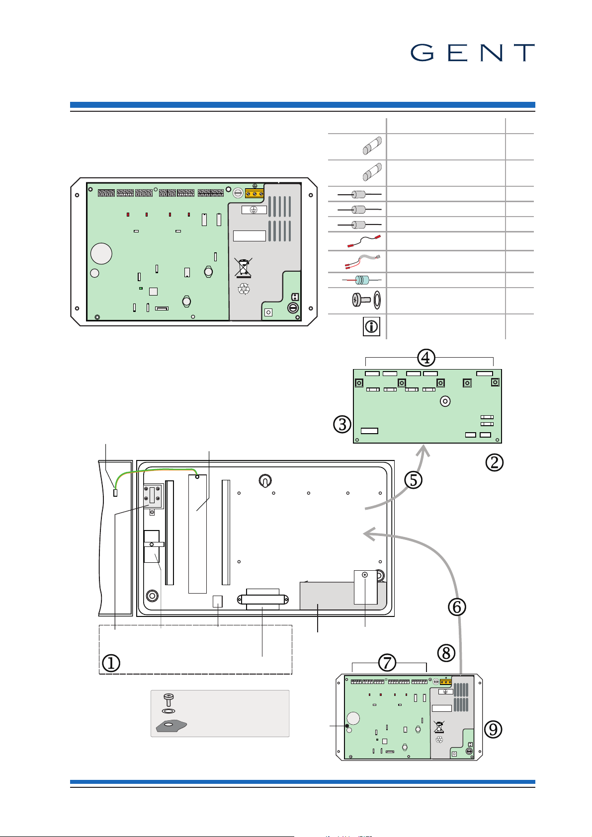
Replacement Interface Board
(VSINTM-PCB-UPG) for 34440 Interface
These instructions cover the installation of a
Replacement Mains Interface Board on a carrier
(VSINTM-PCB-UPG) into a legacy 34440 Mains
powered interface unit.
Spare Parts
Qty
Fuse 3.15A AS Ceramic
(20mm x 5mm)
Fuse 3.15A QB Glass
(20mm x 5mm)
Resistor 5.6K 0.6W 4
Resistor 470R 0.6W 8
Resistor 10K 0.5W 4
Battery Link 1
Battery Lead 1
Capacitor 22uF 35V 4
Screw
(for fixing the carrier)
Instructions 1
1
1
4
4188-1005 issue 1_03/11_Replacement Board for 34440 MPI 1
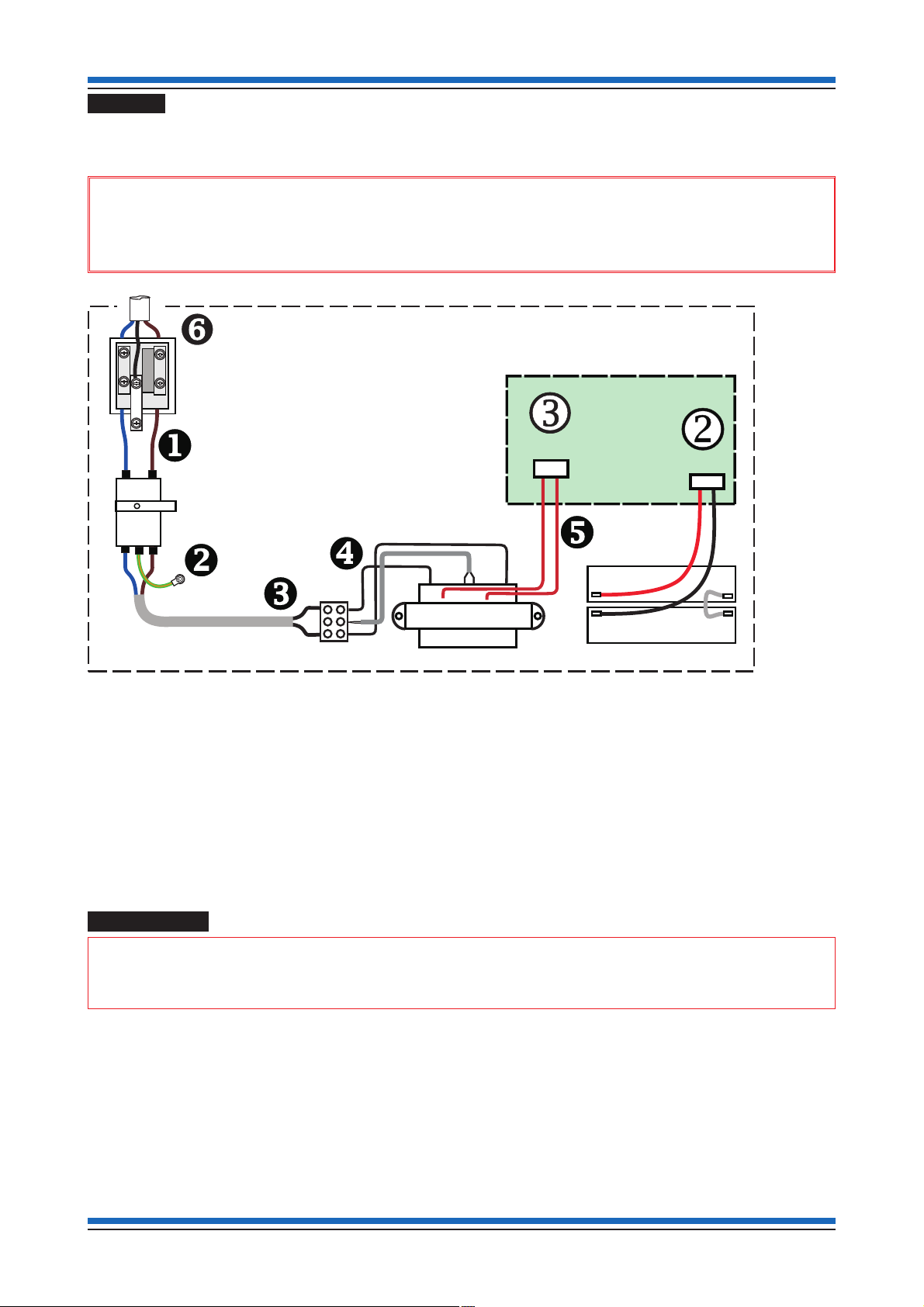
Installation Replacement Mains Interface Board
MAINS
TERMINAL
BLOCK
N
MAINS FILTER
TRANSFORMER TERMINAL BLOCK
TRANSFORMER
AC AC
P7
34440 Mains Interface Board
L
34440 Mains powered interface unit
Battery
P8
+-
+
-
-
+
2 - 12V 2.1Ahr BATTERIES
Removal
a.
Use the [Test/Eng] menu at the control panel and [Stop] the loop circuit on which the 34440 Mains
powered interface unit reside.
&
first completely isolate the mains supply to the unit. Disconnect the wired connection to the Batteries and
then disconnect the battery lead from terminal P8
Before removal of the 34440 Mains Interface Board from the 34440 Mains powered interface unit,
k on the Board.
b.
Now disconnect all the wires uvwxy and z between the MAINS TERMINAL BLOCK and AC
terminals P7
FILTER, TRANSFORMER TERMINAL BLOCK and the TRANSFORMER
discard them safely.
c.
Mark all the other external wires before disconnecting them from their terminal blocks m, this will help
identify the cables for reconnection to the Replacement Mains Interface Board.
d.
Remove 34440 Mains Interface Board from the unit n and discard it safely.
Programming
"
Use the S4 Interface Programmer kit (S4-INTERFACE-PROG) V1.03 or greater and configure the required
'Zone' inputs and 'Sector' outputs on the Replacement Interface Board, in order to simulate the legacy 34440
Mains Interface Board, see instructions supplied with the S4 Interface Programmer kit.
l on the 34440 Mains interface board. Remove the MAINS TERMINAL BLOCK, MAINS
j from the enclosure and
The Replacement Mains Interface Board is factory configured with all four channels as 'Sector' outputs.
2 4188-1005 issue 1_03/11_Replacement Board for 34440 MPI
 Loading...