

Honeywell Gent Viglion EN54, Gent Viglion Compact Voice Alarm, Gent Viglion Compact, Gent Viglion BS Generic Commissioning Instructions
by Honeywell
MIC
Generic Commissioning Instructions
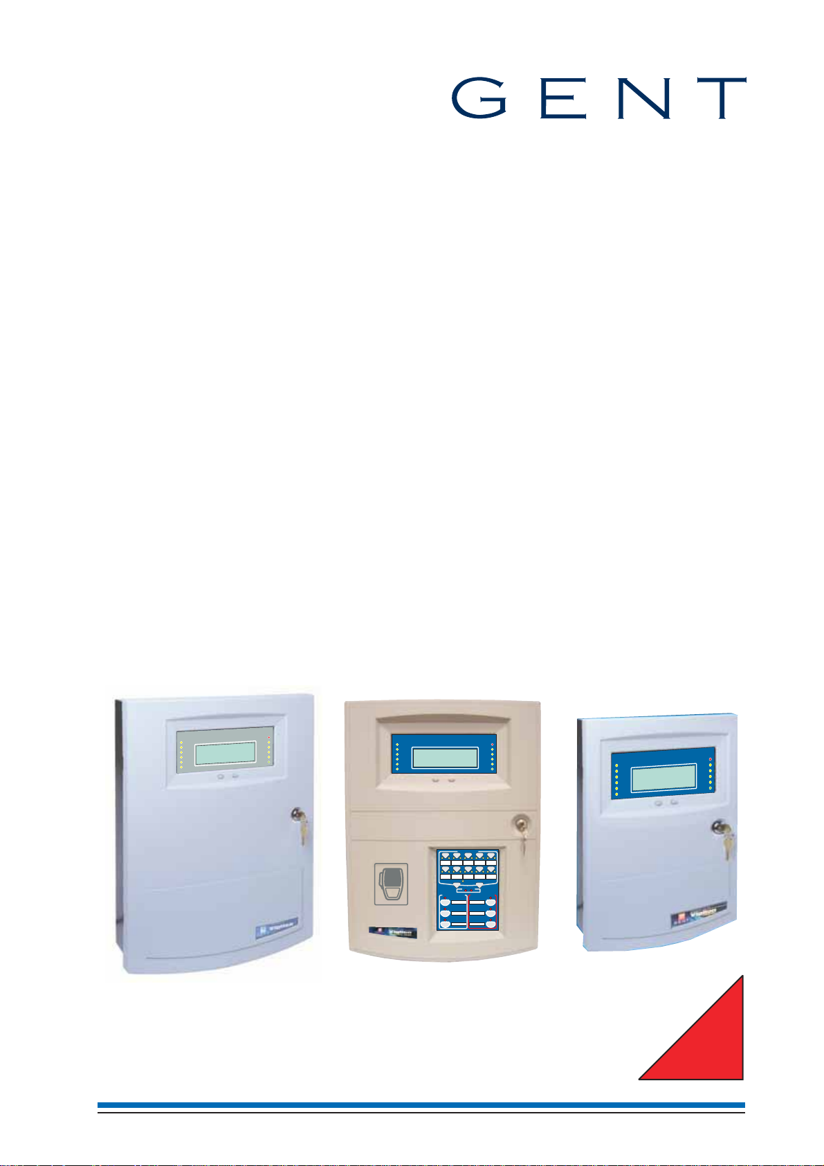
Vigilon range of panels
12345678910111213141516
Zones
17 18 19 20 21 22 23 24 25 26 27 28 29 30 30 32
Fault
PowerFault
Panelhealthy
SystemFault
Vigilon Alarm System
GENT2003
Delay
Designedto EN54 Pt 2 & 4
Test
Disablement
Next
Previous
Fire
Verify
15:45
Sounder
CB253
CB254
Power
12345678910111213141516
Zones
17 18 19 20 21 22 23 24 25 26 27 28 29 30 30 32
Fault
PowerFault
Panelhealthy
SystemFault
VigilonCompact Voice Alarm System
Delay
Test
Disablement
GENT2003
Designedto EN54 Pt 2 & 4
Next
Previous
VoiceAlarm Zones
1423 5
6978
AllZones
Auxiliarymessages
TESTSTART
1
TESTEND
2
STANDDOWN
3
SpeakNow
15:45
ClearZones
Emergencymessages
ALERT
EVACUATE
BOMB
Fire
Verify
Sounder
CB253
CB254
Power
10
1
2
3
12345678910111213141516
Zones
17 18 19 20 21 22 23 24 25 26 27 28 29 30 30 32
Fault
PowerFault
ealthy
h
Panel
SystemFault
Delay
Test
Disablement
Previous
VigilonCompac
Des
GENT2005
gnedto EN54 Pt 2 & 4
i
em
t
s
Sy
t
Next
Fire
Verify
15:45
Sounder
CB253
CB254
Power
ISSUE 2
4188-856_i2_12/06_Generic Vigilon (Compact + VA) Comms. 1

Generic Commissioning instructions
Table of Contents
Preface--------------------4
Associated documents ------------4
Conventions -----------------4
Preliminary information ---------5
Safety information -------------- 5
Abbreviations ----------------5
Pre-visit checks----------------6
Points to remember --------------6
Informing responsible persons ---------7
Pre-commissioning -------------- 7
A typical commissioning process -----8
Product Approval and Standards -----9
Fire detection and alarm control panel -----9
S-Quad Sensors ---------------9
34xxx Sensors ---------------- 10
Sounder Strobe ---------------10
Interface Units ---------------- 10
Panel Controls and indications ------11
Vigilon Compact Panel ------------11
Vigilon Compact VA panel ----------11
Vigilon 4-loop panels (BS panel shown) ----11
Controls and indications ---------12
new Vigilon 4/6 loop Panels -------16
Second fix parts supplied -----------16
Remove the protective covers ---------17
Fitting the inner door -------------17
Printer paper roll --------------- 18
Setting the DKC card ------------- 18
Card installation ---------------18
Terminals ------------------19
Before power-up ---------------20
Mains supply ----------------20
Battery installation --------------21
PSU LED indications -------------22
Write protect link on backplane --------22
EN panel factory settings -----------22
How to configure the 'U' buttons and
CB254 LED ----------------- 23
How to fit the outer door -----------23
Vigilon Compact Panel ---------24
Installing the cards --------------25
Wiring of external circuits-----------27
Battery connection -------------- 28
Switching the essential controls --------28
Factory settings----------------28
Power up------------------- 28
How to configure the monitored input -----30
How to configure the buttons U1 and U2 ----30
How to configure LEDs CB253 and CB254 - - 30
External printer ---------------- 31
Vigilon Compact Voice Alarm Panel - - - 32
Cards and Terminals -------------33
Master Control Board Terminals--------34
Terminals on Audio Control Card (ACC) - - - 34
Factory settings----------------35
Loop Processor Card (LPC) ----------35
Power up------------------- 36
External printer ---------------- 37
How to configure the monitored input -----37
How to configure the buttons U1 and U2 ----37
How to configure LEDs CB253 and CB254 - - 37
How to check and set the audio signal -----37
Indications on power up ---------38
Initial tests ---------------38
Useful menu options -----------39
Panel Buzzer-----------------39
Software version --------------- 39
Password or
Personal Identification Number------39
How to set up the Engineer password -----40
How to set up a Customer password ------40
Address allocation ------------41
Connecting Loop 1 circuit-----------41
With Loop 1 End 1 connected ---------41
How to re-allocate a loop circuit --------42
Checking a loop map-----------43
To find devices on loop circuit --------43
Non Volatile Memory (NVM) ------44
Hardware write protect ------------44
The configuration data held at the panel ----44
Data Back-up & Recovery --------45
To back up loop data to NVM ---------45
To recover loop data from NVM -------45
To 'software' write protect NVM -------45
To 'software' write unprotect NVM ------45
How to electrically erase the NVM ------45
Safe Addressing -------------46
To safe address a device -----------46
To convert from safe to soft address ------46
Loop circuit tests ------------47
Loop resistance and capacitance --------47
How to [Repair] a loop circuit ---------47
Loop short circuit test ------------- 47
Ground break test---------------48
Positive line break test ------------48
Earth fault test ----------------49
Checking device status ----------50
Device checks --------------51
Checking the time averages ----------51
Checking the sensor Exceptions/Subfault codes 52
Exception codes for Optical (heat) (sounder)
sensor -------------------- 53
Exception codes for Heat sensor --------54
Exception codes for Beam sensor -------55
Exception (or Condition) Codes for S-Quads - - 56
Pre Fire, Fire and Super fire -------57
Device States --------------58
2 4188-856_i2_12/06_Generic Vigilon (Compact + VA) Comms.

Vigilon (EN & BS) Compact (VA) panels
Optical heat (sounder) sensor states
(34000 range) ----------------58
Heat sensor states (34000 range) -------59
Beam sensor states (34000 range) -------59
S-Quad Heat sensor states -----------60
S-Quad Optical sensor states ---------60
S-Quad Dual Optical Heat / Optical
Heat sensor states---------------61
S-Quad Dual Optical Heat CO sensor states - - 61
Interface input states -------------62
Installed equipment tests ---------63
Preparation ------------------ 63
Communication to site occupants -------63
Commissioning computer -----------63
Zone 'Test' mode ---------------63
'Commission' mode --------------63
Fire Sensors -----------------63
Manual Call Points --------------64
Interface Units ---------------- 64
S Cubed ------------------- 64
S-Quad-------------------- 65
Sounders -------------------65
Auxiliary equipment -------------65
Repeat panel -----------------65
Mimic Panel ----------------- 65
Deviations from standards-----------65
Vigilon Compact Network --------66
Single Network connections ----------66
Wiring a Copper network -----------67
Single network without domain bridge -----67
Network Card baud and node address Switches - 68
Powering-up the Network -----------68
How to check a Network map ---------68
How to check Network Card status ------69
Fault Finding -----------------69
High errors ------------------69
Single Vigilon Network ---------70
Single Network connections ----------70
Wiring a Copper network -----------71
Wiring a Fibre network ------------71
Single network without domain bridge -----71
Powering-up the Network -----------72
How to check a Network map ---------72
How to check Network Card status ------72
Fault Finding -----------------73
High errors ------------------73
Multiple Vigilon Networks --------74
Domain Bridge using Input Output card ----74
Two networks using Domain bridge IO card - - 74
Star network using Domain bridge IO cards - - 74
IO domain bridge network switch settings - - - 75
Message routing ---------------76
Domain bridge message passing tests -----77
Domain bridge using Fibre Optic network card - 78
FO Domain Network switch settings ------79
Appendix A - Menu maps for EN54 Vigilon
4-Loop panel, Vigilon Compact
(and VA) panels -------------80
Appendix A - Menu maps for BS version 3+
Vigilon 4-Loop panels ----------89
Appendix B - Message Action List ----97
Clearable fault events -------------97
Latching fault events -------------97
Repairable fault events ------------97
Message Action list --------------97
Appendix C - Guidelines for standalone
system commands ------------114
Labels -------------------- 114
Long labels------------------ 115
Sectors -------------------- 117
Delay Blocks -----------------119
Time slots and time blocks ----------120
Zones -------------------- 121
Groups -------------------- 121
Zone Tasks ------------------ 122
Command Builds ---------------123
Sounders Configuration ------------124
3
Mark I------------------- 125
S
S-Cubed Mark II and S-Quad ---------126
Auxiliary Relays --------------- 127
Appendix D - Guidelines for Networked system
commands----------------128
Master Sectors ---------------- 128
Master Groups ---------------- 130
Appendix E - Cards -----------131
Appendix F - Device commissioning - - - 133
4188-856_i2_12/06_Generic Vigilon (Compact + VA) Comms. 3

Generic Commissioning instructions
Preface
This is the second issue of the Commissioning instructions for
the fire alarm system based on the EN54/BS Vigilon 4/6 loop
panels, Vigilon Compact (includes networking) panel and
Vigilon Compact Voice Alarm panel. This manual covers EN
panels having Master Control Card / Master Control Board
software at version 4.3X and BS panels having Master Control
Card software at version 3.9X.
Associated documents
Programming tool manual
EN54 Vigilon 4/6-loop panel Installation instructions
EN54 Vigilon 4/6 loop panel Operating instructions
BS Vigilon 4-loop panel Installation instructions
BS Vigilon 4-loop panel Operating instructions
Vigilon Compact panel Installation instructions
Vigilon Compact panel Operating instructions
Vigilon Compact Voice Alarm panel Installation instructions
Vigilon Compact Voice Alarm panel Operating instructions
Conventions
"
normally hidden in the main text.
This is a note to highlight important text that is
& This is either a caution to prevent damage
to the equipment or a warning to inform of
dangerous conditions that may result in injury or
death.
Symbol Keys
What you will see
What you will hear
4 4188-856_i2_12/06_Generic Vigilon (Compact + VA) Comms.

Vigilon (EN & BS) Compact (VA) panels
Preliminary information
34K Control Panels
This manual does not cover the
34K 4-Loop Control Panels.
For information on 34K 4-Loop
Control panel refer to Vigilon BS
4-Loop Control panels in this
manual.
Both range of panels have
version 3+ software and the only
difference is in the branding.
Safety information
&
1. Do not remove or replace printed circuit boards,
fuses or attempt to wire the control panel with the
panel powered up. Always power down the mains
supply at the fused spur unit (disconnect device).
2. When powering up always power-up the mains
supply first before the battery supply. The
power-down should be done in reverse order.
3. When installing the cards into the master control
board always use anti-static work procedures.
4. Do not use anti-static procedures on live
equipment.
Abbreviations
ADC - Analogue to digital converter
C - Common
CH -channel
DEV - Device
DIL - Dual in line
DKC - Display keyboard card
DPCO - Double pole change over (relay contacts)
EOL - End of line
FAB - First action byte
HF - High frequency
IO or I/O - Input Output (Interface unit)
IP - Ingress protection
LED - Light emitting diode
LPC - Loop processor card
LPCB - Loss prevention council certification board
MCB - Master control board
MCC - Main control card or Main controller card
(CARD 0)
MCP - Manual call point
Mpeg - Moving picture expert group
N/C or NC - Normally closed
N/O or NO - Normally open
NVM - Non Volatile Memory (CARD14)
O/C or OC - Open circuit
OS - Outstation (Loop device or DEV)
PC - Personal computer
PCB - Printed circuit board
PIN - Personal identification number
(usercode, password, access code)
PSU - Power supply unit
PVC - Polyvinyl chloride
QB - Quick blow (fuse)
RAM -Random access memory
ROM - Read only memory
S/C or SC - Short circuit
SAB - Second action byte
SAFE - Software addressed firmware encoded
SPCO - Single pole change over (relay contacts)
SPL - Sound pressure level
T - Anti-surge (fuse)
TBA - To be advised
USB - Universal serial bus
Preliminary information
4188-856_i2_12/06_Generic Vigilon (Compact + VA) Comms. 5

Generic Commissioning instructions
Pre-visit checks
Ensure there are accurate as fitted wiring drawings
¨
available, 2 copies are required.
Any damaged equipment has been noted for
¨
replacement.
Ensure access will be provided to system equipment
¨
installed in the protected premises.
The installer (electrical contractor) will be in
¨
attendance until the installation is proved.
Site contact or representative will be available during
¨
the visit.
Ensure the commissioning tool along with the
¨
associated cables and printer, plus instructions, are
available.
Ensure spare parts are available, such as:
¨
MCP glasses
•
MCP test key
•
Printer paper roll
•
Equipment door keys.
•
Points to remember
Earth leads
All earth leads supplied with the system equipment
¨
must be securely fitted to maintain earth continuity.
Parts for later installation
All unused parts should be retained in their respective
¨
container for safe keeping until required.
Loop wiring
The loop cable should have been connected to the
¨
appropriate terminals at each device, as shown in the
installation manual in accordance with the as fitted
wiring drawings.
Enclosure
Access into equipment enclosure is usually by means
¨
of opening an outer door/cover. A panel may also have
an inner door which may also need opening.
Unattended equipment
Where equipment is to be left unattended, then it is
¨
important to close the door /cover for safety.
Copper fingers
Copper fingers are conductive spring like strips fitted
¨
to metal assemblies. They are fitted to shield against
electromagnetic and radio frequency interferences.
Ensure the copper finger strips are intact and no
damage has occurred. Damaged fingers will
reintroduce the gap to let in/out interferences.
Static precaution
¨
The discharge of static electricity can damage or
degrade sensitive electronic components on printed
circuit boards. Anti-static procedures should be
followed when handling static sensitive boards.
Preliminary information
&
are NOT carried out on live equipment.
Removal and disconnection
¨
Any disconnection of cables or removal of parts of an
assembly must be restored and replaced.
Battery
¨
To prevent damage to batteries and equipment, the
terminals of the battery must not simultaneously touch
any conductive part of the equipment enclosure.
¨
Sealed lead acid battery can have a useful life of up to
5 years from the date of manufacture, it is strongly
recommended that batteries are replaced after 4 years.
The batteries must be disposed of correctly by
following battery manufacturers recommendations.
Powering up
¨
When equipment is being powered up always connect
the mains supply before the battery supply.
Power-down should be done in reverse order.
&
is connected to mains powered equipment.
It is important that anti-static procedures
Arcing may occur when the battery circuit
6 4188-856_i2_12/06_Generic Vigilon (Compact + VA) Comms.

Vigilon (EN & BS) Compact (VA) panels
Panel Buzzer
It may be necessary during commissioning to switch
¨
Off the panel buzzer. It is possible to selectively switch
the disablement, fault, fire, supervisory and command
build buzzer sound to Off or On. It is important to
ensure that the buzzer is switched On for normal
operation after commissioning.
Fire plan
The system should be tested in accordance with the
¨
project specification.
Sensor cover
Each fire sensor installed in the system should have
¨
been fitted with a dust cover during installation. The
dust covers must be removed from all the fire sensors
after the panel loops have been satisfactorily
powered-up and with addresses allocated to each
device ready for further checks and tests.
Site specific installation
Plant equipment interfaced to the system should be
¨
tested to recommendations made in the project
specification.
Test mode (V4) & Commission Mode (V3+)
During commissioning of the system you will need to
¨
switch On the Test/Commission mode. It is important
to switch Off the test/commission mode after the work
is over, to ensure the system operates normally.
Informing responsible persons
It is important to inform the person(s) responsible for the fire
alarm system that the system is being commissioned.
Pre-commissioning
Check the installation of fire alarm equipment with
¨
reference to the most recent as fitted wiring drawings.
Get the feel of the operating condition of areas on the
¨
site:
action the installer to carry out any rectification
•
work plus
report discrepancies for administration purposes.
•
Where the operating condition of an area is not right
¨
for the equipment installed, then the appropriate
replacement action must be taken.
Ensure the fire system equipment is installed in
¨
accordance with the appropriate standards and project
specification.
4188-856_i2_12/06_Generic Vigilon (Compact + VA) Comms. 7
Preliminary information

Generic Commissioning instructions
A typical commissioning process
Things to do when commissioning the system.
Inform responsible person(s)
Inform responsible person(s) that the fire alarm
system is being commissioned and occupants in the
protected premises will hear test alarms.
Ensure occupants are made aware of alternative site
procedures should there be a fire event while the system
is commissioned.
Survey the installation with reference to most recent
as-fitted-drawings.
Ensure the equipment has been installed in accordance
with the appropriate standards and project specification.
Panel preparation
Open the panel doors and:
– Fit the internal cables and install the loop card(s)
– Ensure no external circuits are connected at this stage
– Fit the end of line resistors to the master alarms and
monitored input where applicable
– Connect the external printer to the panel where used
– Ensure no other external circuits are connected to
devices on loop circuits.
Power up
– Fit the batteries and Power up the mains supply
before connecting the batteries.
Initial tests and set ups
– Do a display test
– Set the system clock at the panel
– Configure the printer port if printer is installed
– Set up engineer level password to prevent
unauthorised access to controls.
Address allocation and loop map
- Set interface switches and also also ensure
mains devices on the loop are powered up.
– Connect a loop circuit
– Allocate addresses to loop devices, one loop at a time.
A typical commissioning process
– Set switches on the interface units.
Ensure interface I/O circuits remain
disconnected at this stage.
– Power up mains powered devices
– Upon successful allocation of addresses to loop
devices check the loop map. Check the devices
are installed in their correct location. Repeat the
allocation process on the other loop circuits.
Always power down the panel or device
when
working on the system, for example when
connecting wires and fitting components.
Pre visit checks
Ensure you have:
–
As-fitted-drawings
–
Access to all protected areas
–
Installer is present to rectify wiring faults
–
Tools and spare parts.
Procedures for
Vigilon Compact VA only
Audio loop wiring tests
Connect each audio loop and carry out tests.
Background music and PA microphone
Connect and test Background music system
–
Connect and test PA microphone
–
– Test the emergency microphone
Devices local set up
Ensure all devices on the loop circuits are set up:
– Calibrate speaker circuits
– Adjust volume of audio at each micro DAU
– Adjust volume of S-Cubed
Retrieve the system data to Commissioning computer
Connect the commissioning computer and
retrieve the system data, see Commissioning tools manual.
Configure the system
Configure the system to site specific requirement using the
Commissioning tool and transmit the configuration back
to the control panel, see Commissioning tool manual.
Adjust Beam sensors
Align beam transmitter and receiver heads if installed.
Installed system test
Put the panel in test mode and then carry out tests in
accordance with the recommendations of BS5839:Part 1
and also in accordance with project requirements:
– Fire sensors
– Interface units
· Prior to functional test ensure the I/O circuits remain
isolated. After functional test reconnected the I/O
circuits and where appropriate test the I/O circuits
to project recommendations.
S- cubed - The output volume of an S-cubed can be
–
adjusted using the [Set up] [Setup] [Device] [S-Cubed]
[Volume] command at the panel.
Repeat and Mimic panels
–
· Check events are displayed and indicated
Auxiliary equipment - Prior to the functional test ensure
–
the auxiliary equipment is isolated from the system
– Connect Master alarm and Monitored input circuits
and move the end-of-line resistor to the end of the circuit.
– Sounders - Conduct sound level tests to ensure the
levels do not fall below the requirements.
– Strobe - Check the appropriate S-Quad and S-Cubed
devices provide the visual alarm.
– Messages - Check the correct messages are announced
from the Speakers, S-Cubed and S-Quad devices
where installed.
– Remove the Test mode and ensure any disablements are
re-enabled, such as the disablements of internal buzzer.
Backup
Upon successful allocation of loop circuits back up
the system data to the NVM.
Regularly back up the configuration during
commissioning of the system.
Loop wiring tests
Carry out tests on each loop wiring and [Repair]
the loop after each wiring test.
8 4188-856_i2_12/06_Generic Vigilon (Compact + VA) Comms.
Customer password
Set up a customer PIN / password and inform
responsible person of its existence and use.
Backup of configuration
–
Back up the local system configuration
– Finally if changes have been made to the
local system then retrieve the system to the
commissioning tool for future reference
.

Vigilon (EN & BS) Compact (VA) panels
Product Approval and Standards
Fire detection and alarm control panel
The following fire detection and alarm control panels are LPCB approved.
Product number Description Approval
VIGn EN Vigilon 4 loop panels EN 54 Parts2&4.
n can be 1, 2, 3 or 4
The COMPACT_N, VIG1-24 and VIG1-72 panels described in this manual are pending approval.
S-Quad Sensors
The following S-Quad sensors when operating in the states shown in table below are LPCB approved to the respective standard.
Product number Description Standard
S4-720 Heat sensor EN54 : Part 5 :2002* (heat)
S4-780 Heat Sensor Sounder EN54 : Part 5 :2002* (heat)
EN54 : Part 3 2001 - (sounder tone~)
S4-711 Dual Optical Heat Sensor EN54 : Part 7 :2000* (optical smoke)
EN54 : Part 5 :2000* (heat)
CEA 4021 : 2003-07 Class P heat multisensor detector
S4-711-ST Dual Optical Heat Sensor Strobe EN54 : Part 7 :2000* (optical smoke)
(Strobe - no approval) EN54 : Part 5 :2000* (heat)
CEA 4021 : 2003-07 Class P heat multisensor detector
S4-911 Dual Optical, Heat & CO Sensor EN54 : Part 7 :2000* (optical smoke)
(CO - no approval) EN54 : Part 5 :2000* (heat)
CEA 4021 : 2003-07 Class P heat multisensor detector
S4-711-ST-VO Dual Optical Heat Sensor Speech strobe EN54 : Part 7 :2000* (optical smoke)
(Speech and Strobe - no approval) EN54 : Part 5 :2002* (heat)
EN54 : Part 3 2001 - (sounder tone~)
CEA 4021 : 2003-07 Class P heat multisensor detector
S4-771 Dual Optical Heat Sensor Sounder EN54 : Part 7 :2000* (optical smoke)
EN54 : Part 5 :2002* (heat)
EN54 : Part 3 2001 - (sounder tone~)
CEA 4021 : 2003-07 Class P heat multisensor detector
S4-911-ST-VO Dual Optical Heat CO Sensor Speech & Strobe EN54 : Part 7 :2000* (optical smoke)
(Speech, Strobe & CO - no approval) EN54 : Part 5 :2002* (heat)
EN54 : Part 3 2001 - (sounder tone~)
CEA 4021 : 2003-07 Class P heat multisensor detector
* - these devices are LPCB approved when operating in the LPCB approved STATE, see table below.
"
The required state is configured during commissioning and can be configured at the control panel.
Dual optical, Heat & CO sensor
If an S-Quad sensor is configured to operate a non LPCB state, then this will contravene the LPCB approval.
Device LPCB approved
sensor STATE *
Dual optical & Heat sensor
(S4-711 & S4-711-ST)
(S4-911)
Heat sensor (S4-720) State 0 Class A1 heat
State 0 Medium optical smoke / Class A1 heat
State 5 Medium optical smoke / Class B heat
State 8 Delayed medium optical smoke / Class A1 heat
State 0 Medium optical smoke / Class A1 heat
State 9 Class A1 heat
State 5 Class B heat
Meets
Product Approval and Standards
4188-856_i2_12/06_Generic Vigilon (Compact + VA) Comms. 9
Generic Commissioning instructions
Device LPCB approved
sensor STATE *
Heat Sounder (S4-780) State 0 Class A1 heat
State 5 Class B heat
Dual Optical Heat
Sensor Speech strobe
(S4-711-ST-VO & S4-771)
Dual Optical Heat CO Sensor
Speech & Strobe
(S4-911-ST-VO)
All S4 range of sensor sounder devices meet CEA GEI 1 - 084 Requirements and test methods for input/output devices for use on
the transmission paths of fire detection and alarm system.
~ Meets following tone settings High tone ( Continuous 933Hz) & Alternate (High 933Hz for 0.25s / low 700Hz for 0.25s)
On initial power-up the system selects state 0 for all devices.
State 0 Medium optical smoke / Class A1 heat
State 5 Medium optical smoke / Class B heat
State 8 Delayed medium optical smoke / Class A1 heat
State 0 Medium optical smoke / Class A1 heat
State 9 Class A1 heat
Meets
34xxx Sensors
The following 34xxx sensors when operating in the state shown below are LPCB approved to the respective standard.
Product number Description Approval
Compact "O" Optical sensor EN 54 : Part 7 #
34710 Optical heat sensor EN 54 : Part 5 and Part 7 #
34720 Heat sensor EN 54 : Part 5 #
34770 Optical heat sounder sensor EN 54 : Part 5, part 7 and LPCB requirements #
34800-EN Manual Call Point EN54 Part 11
34842-EN Manual Call Point EN54 Part 11
If a 34xxx sensor is configured to operate a non LPCB approved state, then this will contravene the LPCB approval.
¨
* - these devices are LPCB approved when operating in the LPCB approved STATE, see table below.
"
commissioning and can be configured at the control panel.
Optical heat sensor
(34770 and 34710)
Heat sensor (34720)
Product Approval and Standards
On initial power-up the system selects state 0 for all devices.
All the LPCB states applicable to fire sensors are shown below. The required state is configured during
Device LPCB approved sensor
STATE #
State 0 Medium smoke sensitivity with Grade 2 heat
State 8 Smoke sensing with delay + Grade 2 heat
State 12 Grade 1 heat only
State 13 Grade 2 heat only
State 0 Default sensitivity
State 1 Grade 1
Heat sounder
(34780)
State 0 Grade 2 heat
State 12 Grade 1 heat
Meets
Sounder Strobe
The following S-cubed Mark 1 range of products are LPCB approved to EN 54 : Part 3
S3-SN-R, S3-SN-W, S3IP-SN-W, S2IP-SN-R, S2IP-SN-W, S2IP-SN-R3, S2IP-SN-W3, S3-SN-ST-RR, S3-SN-ST-WR,
S3IP-SN-ST-RR, S3IP-SN-ST-WR, S3IP-SN-ST-RW and S3IP-SN-ST-WA.
Interface Units
The following products are approved to prEN 54 Part 18 : 2005
34410 Zone module (loop powered)
34450 4 Channel Input / Output Interface unit (loop powered)
34415 Single channel Interface unit
10 4188-856_i2_12/06_Generic Vigilon (Compact + VA) Comms.
Vigilon (EN & BS) Compact (VA) panels
Indi
g
MIC
g
I
I
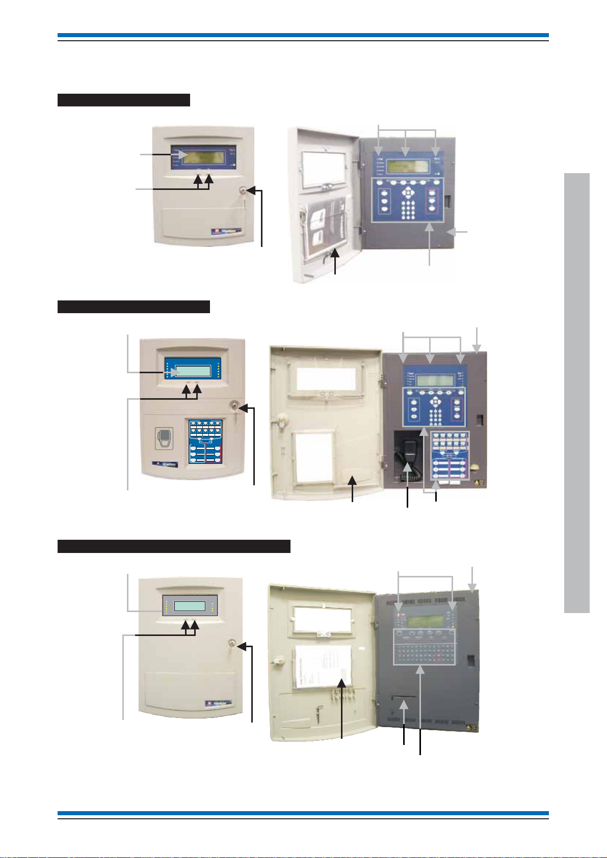
Panel Controls and indications
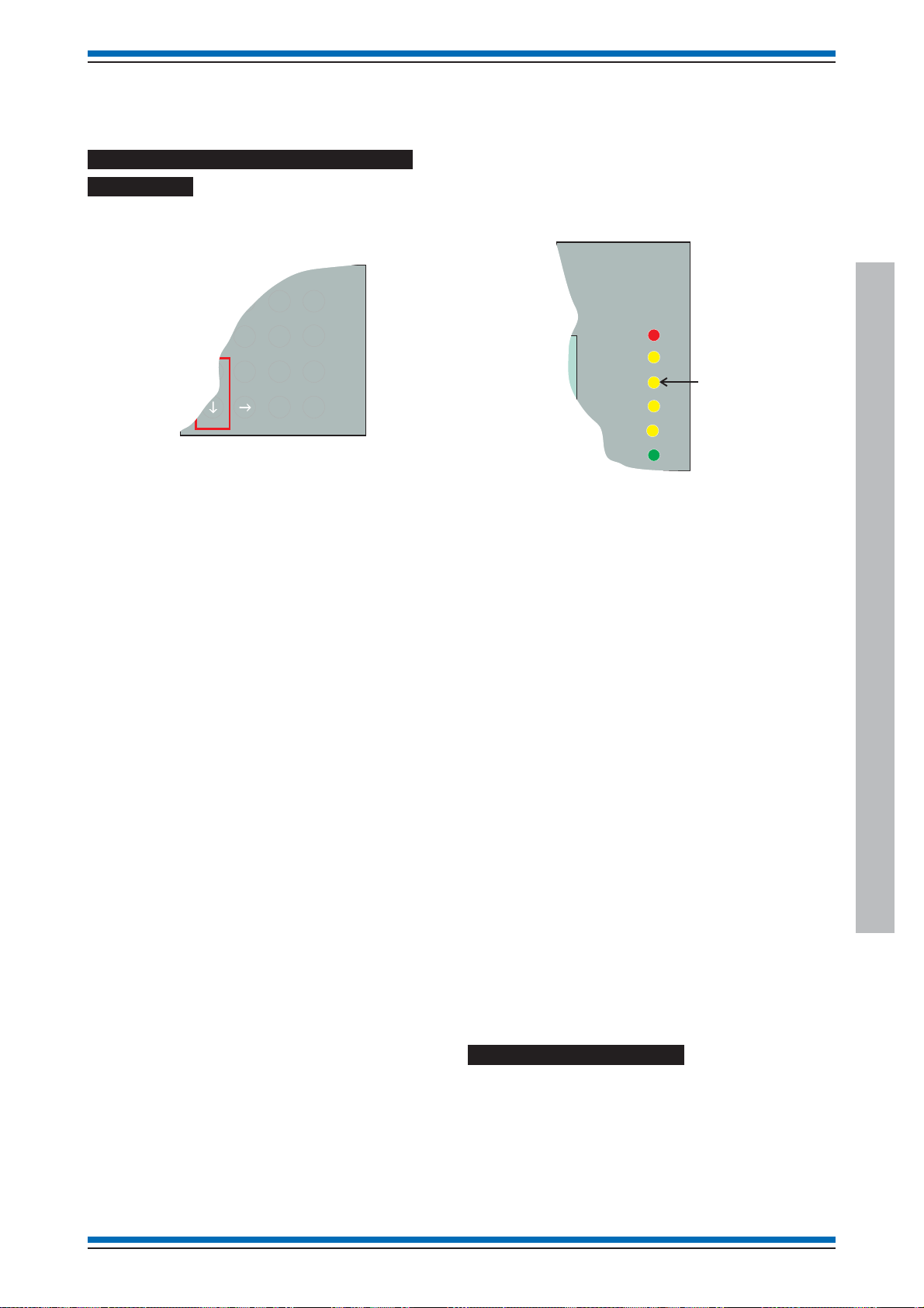
Vigilon Compact Panel
Outer door
Message
Display
Access level 1
Controls
to scroll events
Key lock
to open
Vigilon Compact VA panel
Message display
12345678910111213141516
Zones
17 18 19 20 21 22 23 24 25 26 27 28 29 30 30 32
Fault
PowerFault
Panelhealthy
SystemFault
VigilonCompactVoice Alarm System
Delay
GENT2003
DesignedtoEN54 Pt 2 & 4
Test
Disablement
Next
Previous
the outer door
Fire
Verify
15:45
Sounder
CB253
CB254
Power
Operating instructions
and Lo
Outer door
Book
cations
Indications
Inner door
Access level 2
Controls
nnerdoor
VoiceAlarmZones
1423 5
6978
10
ClearZones
AllZones
SpeakNow
Auxiliarymessages
Emergencymessages
ALERT
TESTSTART
1
1
TESTEND
EVACUATE
2
2
STANDDOWN
BOMB
3
3
Access level 1
Controls to scroll events
Key lock to open
the outer door
Vigilon 4-loop panels (BS panel shown)
Message display
VigilonFireSystem
GENT2005
DesignedtoEN54 Pt 2 & 4
Previous Next
Fire
15:45
Verify
CB253
CB254
Power
Fault
PowerFault
SystemFault
Delay
Commission
Warning
Pocket for
Operating instructions
and Lo
Book
Outer door
Emergency
Microphone
Indicators
Access level 2
Controls
nnerdoor
Panel Controls and indications
Access level 1
Controls to scroll events
Key lock to open
the outer door
Pocket for
Operating instructions
and Log Book
Printer
Access level 2
Controls
4188-856_i2_12/06_Generic Vigilon (Compact + VA) Comms. 11

Generic Commissioning instructions
Fire
Controls and indications
Panel
buzzer
Vigilon Compact panel or
Vigilon Compact Voice Alarm panel
12345678910111213141516
Zones
17 18 19 20 21 22 23 24 25 26 27 28 29 30 30 32
Fault
Power Fault
System Fault
Delay
Test
Disablement
Menu On/Off
F1 F2
Verify
U1
U2
Previous Next
Enter
ABC
1 2 3
GHI
JKL
4 5 6
PQRS
TUV WXYZ
7 8 9
THRU
INS
0
0
F3 F4
DEF
MNO
BKSP
DEL
Fire
Verify
Sounder
CB253
CB254
Power
Cancel Buzzer
Sound Alarms
Silence Alarms
Reset
Not fitted on
BS Vigilon 4-loop
panel
BS Vigilon 4-loop panel:
Commission
Warning
EN Vigilon 4-loop panel or
BS Vigilon 4-loop panel
12345678910111213141516
Zones
17 18 19 20 21 22 23 24 25 26 27 28 29 30 30 32
Fault
Power Fault
System Fault
Delay
Test
Disablement
Menu On/Off
F1 F2
Sound Alarms
"
!
1
23
QW
S
A
#
ER
DF
Silence Alarms
%
$
4
5
T
GHJ K L
BS Vigilon 4-loop panel:
Previous Next
F3
Reset
& *
^
6
890
7
F4
(
)
YU IOP
+
-
:
;
;
,
.
Cancel Buzzer
Verify
Insert
Delete
Enter
NOT USED
Fire
Verify
Sounder
CB253
CB254
Power
U1
U2
U3
ZXC
12 4188-856_i2_12/06_Generic Vigilon (Compact + VA) Comms.
VB
NM
SpaceShift
U4
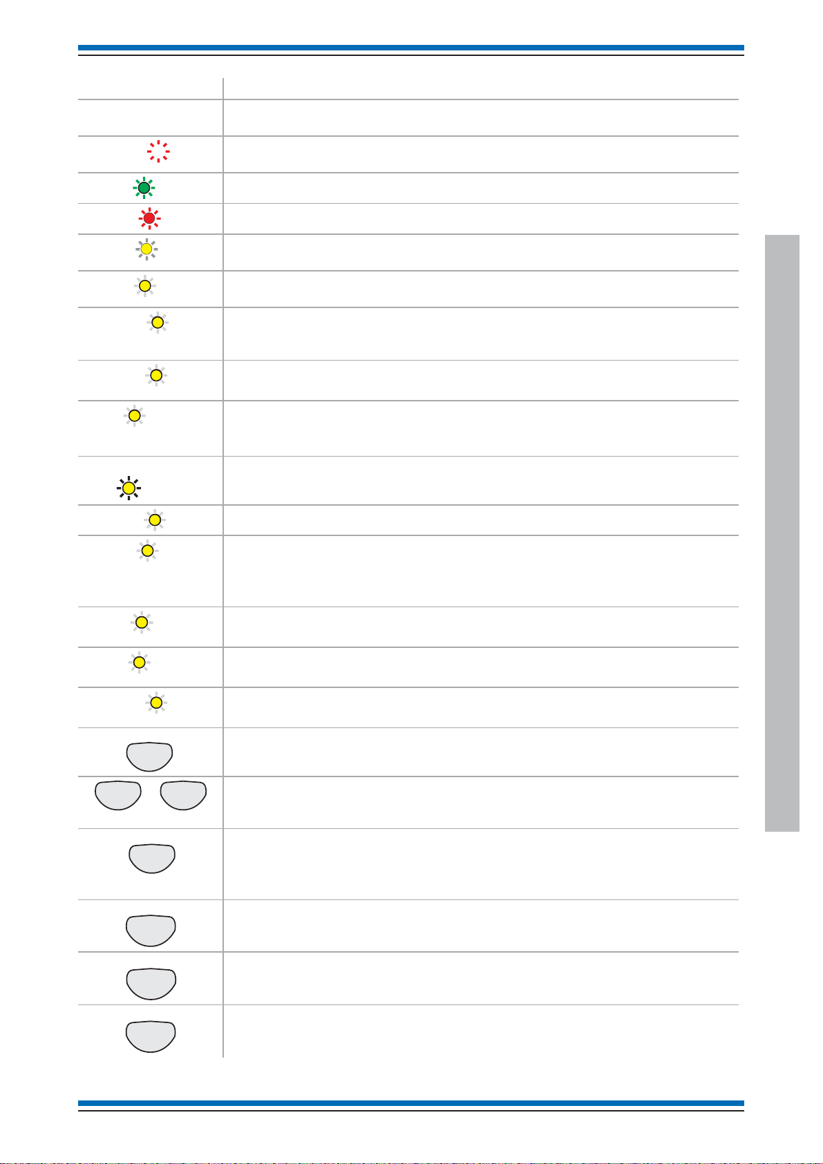
Indicators and controls Description
V
/Off
t
r
S
s
S
s
R
Display The 'display' provides messages of the system status and events. Most panel display have
8 lines by 40 characters per line display.
Zones 1
Power
Fire
erify
Fault
System Fault
(red)
(green)
(red)
(amber)
(amber)
(amber)
Hidden-until-lit fire zone indicators. When "Zones" text and number(s) are illuminated it
indicates that a FIRE has been detected in the specified zone(s).
When illuminated it indicates that a supply to the panel is present.
When illuminated it indicates that a FIRE has been detected in the protected premises.
When illuminated it indicates that the Verify button has been pressed and the alarm
sounders in the system are delayed from sounding.
When illuminated it indicates that a FAULT has been detected in the fire detection and
alarm system or in the audio system.
When illuminated it indicates that a fault has occurred with the system processor. It is
important to investigate this fault because the fire alarm system may not be able to
detect fires.
Disablement
Warning
(amber)
(amber)
Applicable for EN Vigilon panels only
When illuminated it indicates that a part of the system has been disabled.
Applicable for BS Vigilon panels only
When illuminated it indicates that a part of the system has been disabled, delayed or not
functioning.
CB253 or CB254
When illuminated it indicates command builds 253 or 254 has been activated.
Vigilon (EN & BS) Compact (VA) panels
Power Fault
Sounder
Delay
Test
Commission
MenuOn
F1 F4
Cancel Buzze
ound Alarm
ilence Alarm
(amber)
(amber)
to
Nex
(amber)
(amber)
(amber)
(amber)
When illuminated it indicates the battery or mains supply to the panel has failed.
EN Vigilon panels only
When illuminated (always with either the FAULT light or the DISABLEMENT light) it
indicates that there is a sounder fault (flashing indication) or sounder disablement (steady
indication).
EN Vigilon panels only
When illuminated it indicates that one or more delay blocks are setup on the panel.
EN Vigilon panels only
When illuminated it indicates one or more zones are in Test mode.
EN Vigilon panels only
When illuminated it indicates panel is in commissioning mode.
Pressing Menu On/Off enables/disables the on screen menu facility which gives access to
the system menus.
The 'Fn' buttons are used to select functions and sub-functions of the system menus which
appear on the display. Each option in the menus, corresponds to one of the function
buttons and pressing a button will select the option which appears above it on the display.
The Cancel Buzzer button when pressed will stop the internal panel buzzer from
sounding.
Note the local buzzer is automatically silenced when the emergency microphone is being
used to announce live speech, on Vigilon Compact VA panel.
Pressing the Sound Alarms button will announce evacuate message and sound evacuate
alarms. This button is only pressed in an emergency or at other agreed times, for example
when conducting a system test or practice evacuation.
Pressing the Silence Alarms button will stop emergency message announcements and
silence the system alarms.
Controls and indications
eset
Pressing the Reset button will clear any fires and return the panel to its normal state. If a
fire condition occurs immediately after reset then the indicated device should be
investigated.
4188-856_i2_12/06_Generic Vigilon (Compact + VA) Comms. 13

Generic Commissioning instructions
DEF
Indicators and controls Description
Verify
Applicable for Vigilon Compact (& VA) panels only:
U1
U2
If the Verify facility has been set up, then pressing the Verify button in the event of a fire
condition, increases the time delay before the sounders are activated. This gives the user
time to investigate the cause of the alarm and option of cancelling the alarm within the
delay time period.
These buttons can be configured during commissioning to action user defined functions,
such as disablement of devices in areas where smoke may be generated or where plant
shutdown is required.
The function of these buttons should be written on the label that is fitted on the back of
the outer door.
The Vigilon 4-loop panels have four configurable buttons.
These four buttons are used to scroll the displayed text.
ABC
1 2 3
GHI
JKL
4 5 6
PQRS
TUV WXYZ
7 8 9
THRU
INS
0
0
Enter
MNO
BKSP
DEL
These buttons allow data to be entered manually at the control panel.
When entering a label each press of a key will scroll the character string, for
example:
key 2 will scroll
ABC2abc.
key 1 will scroll 1?,.;&*/
The bottom row of text keys explained:
The button is used to enter a SPACE between characters
The INS key allows text to be moved one position to the right
The DEL key allows a character to be deleted
The BKSP button will delete previous character.
When entering a data range, such as a range of devices
ThekeyTHRU(-)isused to enter a range, for example1-5.
This is pressed to acknowledge an entry of data such as a label.
Controls and indications
14 4188-856_i2_12/06_Generic Vigilon (Compact + VA) Comms.

Applicable for Vigilon Compact VA panel only
s
Auxili
s
E
s
1423 5
Vigilon (EN & BS) Compact (VA) panels
Voice Alarm Zones
n
(green)
All Zones
6978
All Zones
Speak Now
Auxiliary messages
TEST START
1
TEST END
2
STAND DOWN
3
Emergency messages
EVACUATE
Clear Zones
ALERT
BOMB
10
1
2
3
Pressing one or more of the 10 buttons selects the Voice Alarm Zone to which emergency
or auxiliary messages, or emergency microphone is to be announced. The two LEDs
beneath flash alternately to show the Voice Alarm Zone has been selected.
On selecting the required emergency or auxiliary message only one of these LEDs
change to steady or flashing indication determined by the type of audio to be outputted to
the selected Voice Alarm Zones. The left LED indicates auxiliary message selection
while the right LED indicates emergency message selection.
Pressing the All Zones button allows quick selection of all Voice Alarm Zones. The
accompanying LED gives a steady indication when the button is pressed.
(green)
Clear Zone
Speak Now
Speak Now
Controls and indicationsControls and indicationsControls and indicationsControls and indications
ary message
n
mergency message
Pressing Clear Zones button will clear selected Voice Alarm Zones, also when auxiliary
messages are being announced pressing this button will silence the announcements.
When illuminated the system is ready to allow live speech announcement to selected
Voice Alarm Zones via the Emergency microphone.
(red)
The indicators are lit following selection of Voice Alarm Zones and on pressing the Press
to Talk (PTT) button on the Emergency microphone.
If the Press to Talk button is released the Speak Now indicators will flash and switch off
(red)
after 20seconds duration or immediately switch off on pressing the Clear Zone button.
When illuminated the system is announcing auxiliary message n to the selected Voice
Alarm Zones.
Controls and indications
The indicator is lit following selection of Voice Alarm Zones and on pressing the
required Auxiliary message button.
(red)
When illuminated the system is announcing emergency message n to the selected Voice
Alarm Zones.
The indicator is steady or flashing determined by type of emergency message being
n
announced to Voice Alarm Zones.
(red)
4188-856_i2_12/06_Generic Vigilon (Compact + VA) Comms. 15
Generic Commissioning instructions
C
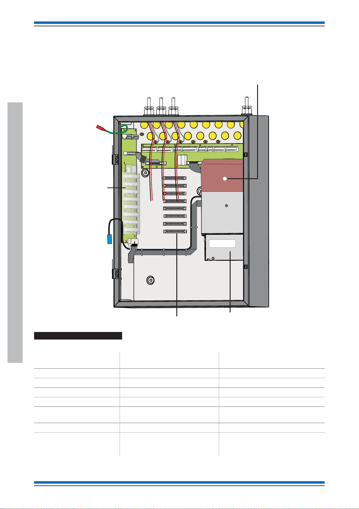
new Vigilon 4/6 loop Panels
The following procedures assume the respective 1st fix assembly for the new Vigilon 4 loop (VIG1-24) / 6 loop (VIG1-72) panel is
already installed. The first fix backbox assembly may be surface or flush mounted.
The second fix parts must now be installed before powering up the control panel.
¨
Cables of external circuits
Earth to
inner door
Hinge
points for
inner and
outer doors
Transparent
cover over
backplane
ardboard cover
over PSU
Mains cable
Second fix parts supplied
¨
Check the second fix parts supplied:
new Vigilon 4/6 loop Panels
Parts
Inner door assembly
Battery Pack (2 x 12V 21Ah)
Battery box
Outer door assembly
Master Control Card
(post Aug 2006)
Loop card
Spares pack
see installation manual for
pack content
Printer 0V
Hinge
points for
inner and
outer doors
Cardguides
new EN Vigilon 4 loop Control
panel (VIG1-24)
PSU
EN Vigilon 6 loop Control panel
(VIG1-72)
11
12
1
11
11
1 (Option of up to 4 maximum) 1 (option of up to 6 maximum)
1pack 1pack
16 4188-856_i2_12/06_Generic Vigilon (Compact + VA) Comms.
Vigilon (EN & BS) Compact (VA) panels
Earth to
inner door
Cables of external circuits
Printer 0V
Transparent
cover over
backplane
WARNING
REMOVAL OF COVER
EXPOSES HIG
H VOLTAGES
Transit position of
printer paper roll
and holder pin held
together with an elasticband
Hinge point
Paper roll
holder bracket
Connector for
printer 0V
Earth spade
for connection from
backbox
Inner door
Preformed ribbon
cables held together
under masking tape
to be fitted during
commissioning
Card guide
Danger
Masking tape
BACKBOX (Part view)
Backbox
Inner
door
locating
the hinge pin
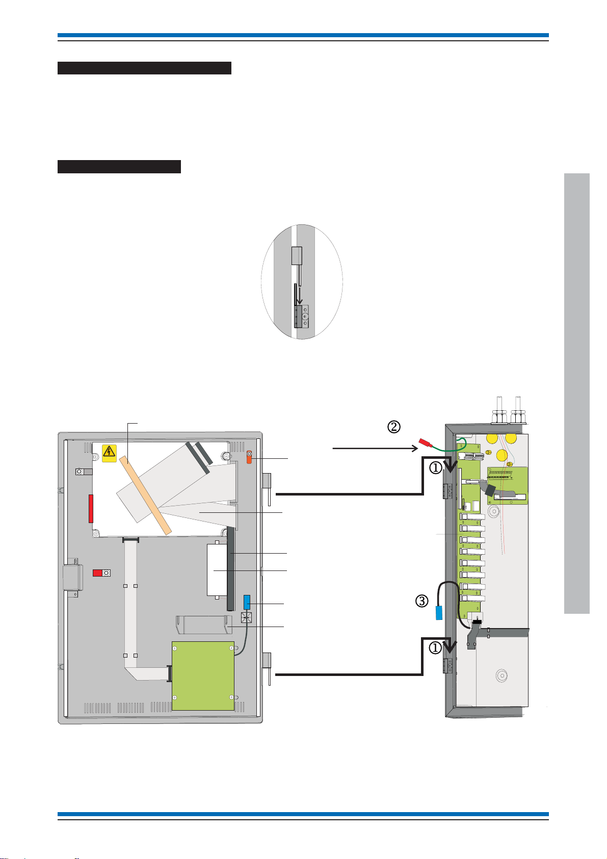
Remove the protective covers
PSU Cardboard cover
Remove the cardboard protection cover fitted over the PSU. The cover is held in by a retaining clip.
Backplane transparent cover
Remove the transparent protection cover fitted over the backplane.
Fitting the inner door
Locate the hinge pints on the inner door assembly into the two hinge pin holes j on the backbox outer face.
Fit the earth lead from the backbox to the inner door spade connector k.
Fit together the two blue connectors of the printer 0V leadsl, the leads are located at the inner door and backbox intersection.
HV
new Vigilon 4/6 loop Panels
4188-856_i2_12/06_Generic Vigilon (Compact + VA) Comms. 17

Generic Commissioning instructions
D
WARNING
REMOVALOF COVER
EXPOSESHIG
HVOLTAGES
Inner door assembly
Danger
Backpl
Printer paper roll
"
band to the card guide on the inner door.
Remove the paper roll from the card guide and install paper.
Ensure the paper roll enters the printer mechanism as shown .
The printer paper roll is secured with an elastic
oor
Printer
mechanism
Paper
feed knob
Paper
roll
Fold paper end thus
before attempting to
feed it through printer
&
On the outside of the inner door there is a paper
feed knob, DO NOT turn the knob in an upwards
direction as this may damage the integral printer.
Upon completion of all commissioning work a new paper roll
should be fitted.
Setting the DKC card
Card installation
&
always use anti-static work procedures. DO NOT use
anti-static procedures on live equipment.
"
DKC and Commissioning tool. The DKC now connects
directly to the new MCC card and the Commissioning tool
is connected via the USB on MCB.
The two ribbon cables held together under a masking tape on the
DKC assembly must be routed into the backbox and connected
to the Master Controller Card.
"
clamp on the backplane and then plug the master
controller card before the card is fitted to the backplane.
40 way ribbon
When installing the cards into a backplane
An IO Card is not required for connection to
Ensure the ribbon cable is secured under a
ane
Secure the two ribbon
cables (at the fold) under the clamp
located on the backplane
The link, switch and pot on the DKC are factory configured as
shown in below. The switch can be reconfigured for required
baud rate and domain address.
DKC ASSEMBLY
OFF
SW1
8
7
6
5
4
3
2
1
ON
P6
P2
Leave this link connected
The link is used to bypass
a keyswitch not used
on this product
new Vigilon 4/6 loop Panels
HV
Factory set link position:
Control buttons active
Control buttons are active
Control buttons:
Sound alarms button
Silence alarms button
Reset button
Verify button
Control buttons are inactive
or
Baud Rate Domain address
2 Baud
1
Off Off 1200 Off Off Off Off Off Off 64
3
5678Addr.
4
Off On 2400 Off Off Off Off Off On 1
On Off 9600 Off Off Off Off On Off 2
On On 19200 etc
On On On On On Off 62
On On On On On On 63
Factory set domain address - 1 with 19200
baud (SHADED)
20 way ribbon
Card guides
P1 CARD 0
P2 CARD15
P3 CARD 1
P4 CARD 2
P5 CARD 3
P6 CARD 4
P7 CARD 5
P8 CARD 6
&
Master Controller Card (MCC)
to be fitted to socket
P1 CARD 0 on backplane
Backplane
Always ensure the panel is completely
Use the USB port on
the MCC to connect to
the Commissioning tool.
Main Controller Card or
Local Controller Card (SUPPLIED)
Network or IO Card (Optional)
Loop Processor Card (SUPPLIED)
or RS232
Loop Processor Card or RS232
(Option)
Loop Processor Card or RS232
(Option)
Loop Processor Card or RS232
(Option)
Network or RS232 or
Loop Card#
Network or RS232 or
Loop Card#
# for VIG1-72 only
powered down before removal or fitting of cards into
the backplane. Power down the battery supply
before the mains supply. The power up should be
done in a reverse order.
¨
Ensure all the cards are installed in the correct location
in the backplane and are firmly seated in their
respective slots.
18 4188-856_i2_12/06_Generic Vigilon (Compact + VA) Comms.

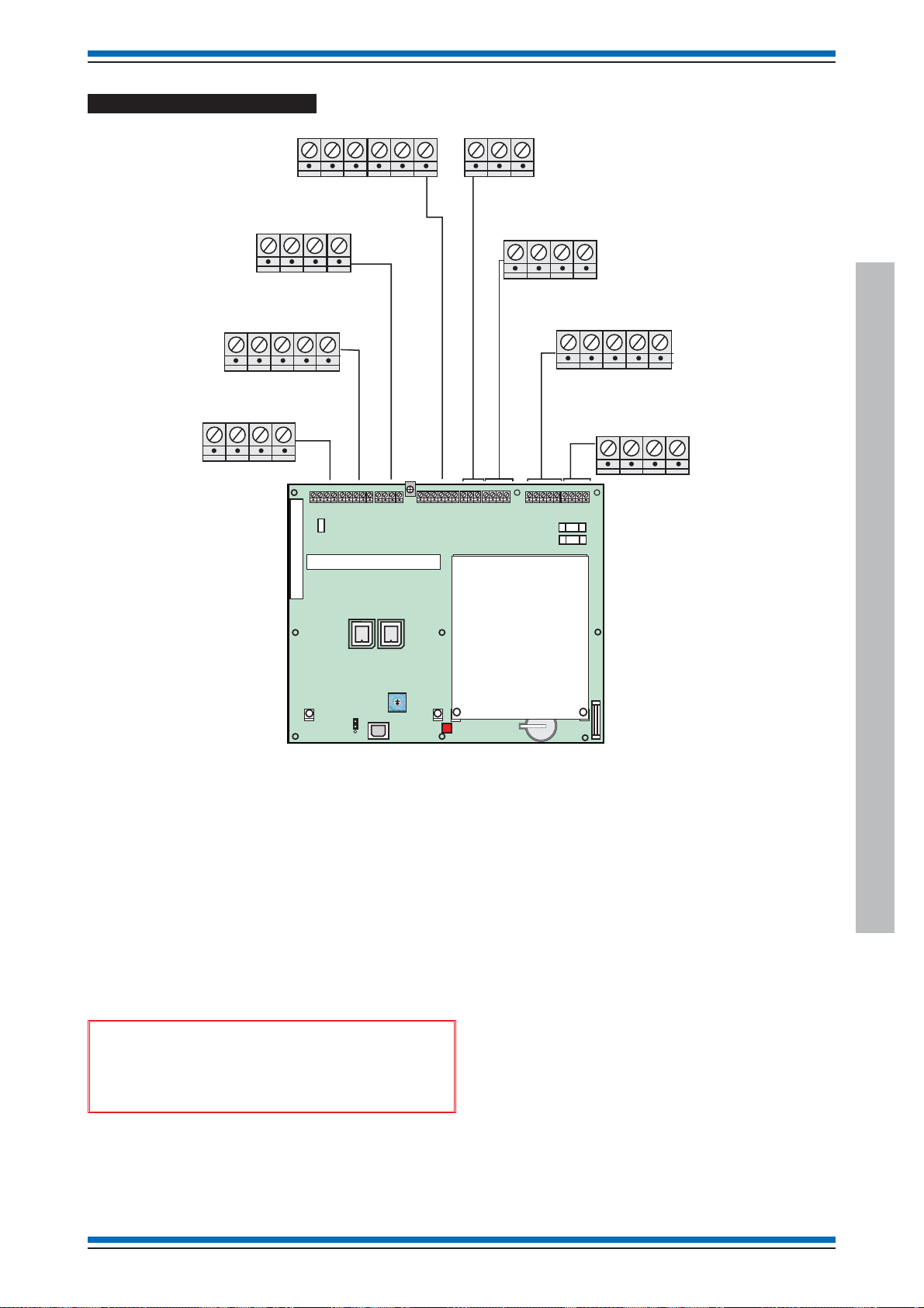
Terminals
Backplane
Terminals for card in
slot P8 of Backplane
123456 78
P10
Terminals for card in
slot P7 of Backplane
123456
P11
NE L
3.15A Antisurge
20mm x 5mm
fuse
Terminal card
LOOP 4
L1 0V L2 0V
Vigilon (EN & BS) Compact (VA) panels
LOOP 3
L1 0V L2 0V
P2
LOOP 2
L1 0V L2 0V
LOOP 1
L1 0V L2 0V
P3
Master alarm
M1+ M1- M2+ M2-
Clean C
NC C NO
P5
RS485
-ve 5V +ve 0V
RS232
TxCTSRxRTS
P4
Auxiliary Relay 1
NCCNONCCNO
P7
Battery connections
B1+ B1- B2+ B2- TH+ TH-
P9
P6
Auxiliary Relay 2
NCCNONCCNO
P8
new Vigilon 4/6 loop Panels
4188-856_i2_12/06_Generic Vigilon (Compact + VA) Comms. 19

Generic Commissioning instructions
Before power-up
With the exception of the mains cable ensure the
¨
following external cables are left disconnected at this
stage of commissioning:
all loop circuits
•
clean contacts
•
auxiliary circuits
•
master alarm circuits, only the end-of-line resistor
•
(22K Ohm) should be fitted to the terminals to
inhibit a master alarm circuit fault indication.
RS232/RS485
•
"
the individual standalone systems are fully
commissioned.
Ensure all cards are securely fitted into their
¨
appropriate slots on the backplane.
Ensure all ribbon cables are securely fitted into their
¨
respective sockets.
Battery information
A networked system is commissioned after all
Mains supply
&
designed to be powered from IT Power systems.
"
earthed.
Ensure the mains supply cable enters the equipment via a
dedicated cable entry point, which is located adjacent to the
mains terminal block and is also segregated from any loop wiring.
Mains supply to any fire alarm control and indicating
¨
equipment must be via an unswitched 5A fused spur
unit. A disconnect device must be provided to
disconnect both poles and must have a minimum gap
of 3mm. The Disconnect device should be available as
part of the building installation and must be easily
accessible after installation is complete.
The fused spur isolator cover should be marked:
¨
FIRE ALARM - DO NOT SWITCH OFF
Fire alarm system products are NOT
All mains powered equipment must be
"
batteries which can have a useful life of up to
5 years from the date of manufacture. It is strongly
recommended that batteries are replaced after 4 years of
use. Batteries must be disposed of as per
recommendation made by battery manufacturer.
&
The panel makes use of sealed lead acid type
Always use the recommended
replacement battery. As there is a risk of an
explosion if incorrect batteries are used.
new Vigilon 4/6 loop Panels
&
Hazardous voltage remains after
operation of a protection fuse. Take appropriate
action to guard against the risk of equipment having
exposed live mains supply.
Dedicated mains supply
from consumer unit
5A Unswitched
fused spur unit
mains cable
mains
Panel
must be sleeved
Use cable ties
(supplied)
ferrite
core
(supplied)
Gland
35mm
45mm
cable
50mm
270mm
L
N
P2
PSU PCB
The mains cable must be stripped
back to the length shown to allow
live and neutral wires to be wound
through the ferrite core.
20 4188-856_i2_12/06_Generic Vigilon (Compact + VA) Comms.
5mm
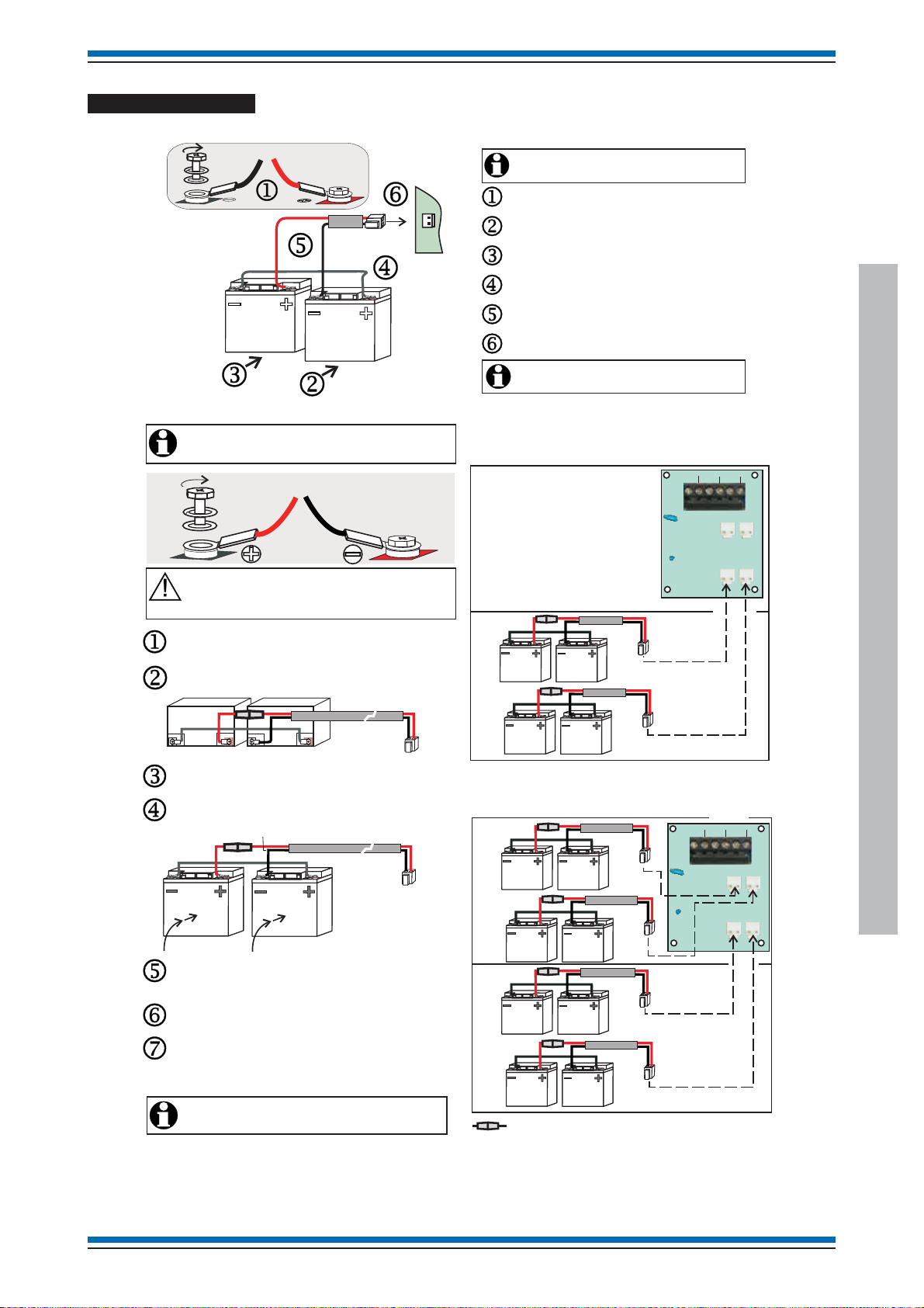
Battery installation
VIG1-24 panel battery installation
Black
VIG1-72 panel battery installation
It is recommended that the mains supply is switched
during battery installation.
off
Red
Red Black
Red
Black
White
Vigilon (EN & BS) Compact (VA) panels
It is recommended that the mains supply is switched
during battery installation.off
Fit the bolt, spade connector, washer, spring washer to
BT+
BT-
P20
each battery terminal.
Insert hand battery into the back box.right
Insert hand battery into the back box.left
Fit the link lead (white) to outer + and - spade connectors
on the two batteries.
Fit the battery lead assembly to inner + and
- spade connectors of the two batteries observing polarity.
Plug the battery connector into connector P20 located on
the bottom left of power supply PCB.
The panel will only power up after the mains supply
is switched on.
(red & black)
4 - 12V 21Ah batteries
Battery Box
Upper
shelf
P6
TH+
BT1-
P4
BT2-
BT2+BT1+
P3
TH-
Ensure the batteries are held in place while they
are being wired. Ensure the battery terminals
do not come into contact with the metal enclosure.
Place the two batteries in the lower shelf and lay them
horizontally with terminals facing outwards.
Fit the bolt, spade connector, washer and spring
washer to each battery terminal as shown above.
White.
Red Black
Fit the white link lead and then fit the red/black
fused lead to the battery terminals.
Raise the two batteries to an upright position
and push them back into the enclosure.
Red
Black
White.
Route the battery red/black lead through hole in shelf
and connect to the respective connectors on PCB,
located on the top right side of the enclosure.
Add two more batteries 'B' to the lower shelf and repeat
procedures to .
jn
Where required, add four batteries to the upper shelf,
follow procedures to . The only exception
jo
is that the red/black lead is directly connected to the
respective upper connectors on the PCB.
The panel will only power up after the mains supply
is switched .
on
TH1
Lower
shelf
A
B
8 - 12V 21Ah batteries
Battery Box
Upper
shelf
A
B
Lower
shelf
A
B
In-line fuse rated 10A QB ceramic 20mm x 5mm
P6
TH1
P1
P2
TH+
BT1-
P4
P1
BT2-
BT2+BT1+
P3
P2
TH-
new Vigilon 4/6 loop Panels
4188-856_i2_12/06_Generic Vigilon (Compact + VA) Comms. 21
Generic Commissioning instructions
Backpl
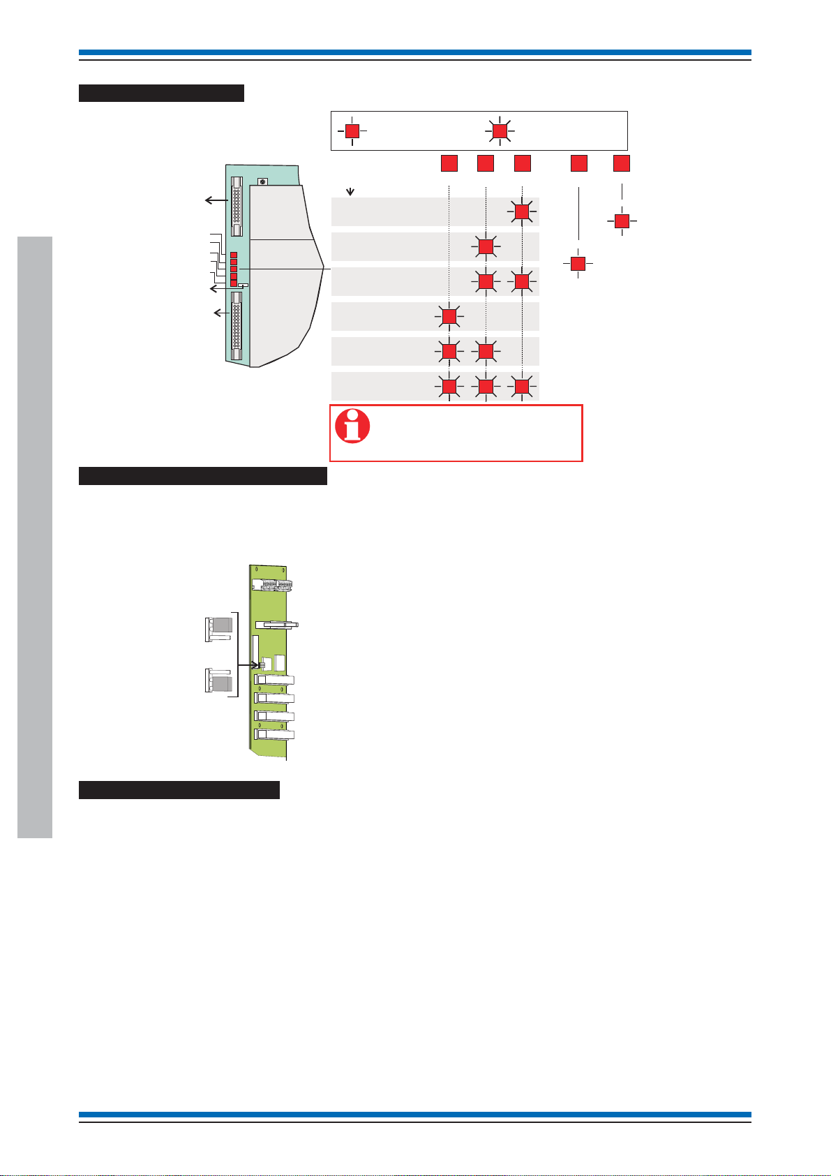
PSU LED indications
Flashing indication
Steady indication
PSU
Ribbon cable
to Terminal Card
connector P10
Spade connector
for 0V lead to printer
Ribbon cable to
connector P12
LD1
LD2
LD3
LD4
LD5
Backplane
LD2
LD3
ERROR
P7
LD1
LD2
LD3
LD4
P5
LD5
P11
RAM write/read
test failed
ROM checksum error
EEPROM checksum error
EEPROM stuck in
busy mode
EEPROM reinitialised
EEPROM read does
not match RAM copy
The above LEDs flash 1s on and 1s off.
When LED is ON it indicates an error.
For more than one error the LEDs
will flash in sequence.
LD4
LD1
LD5
Indicates
communicating
with MCC
Indicates Thermistor is O/C or
S/C or 43V boost test has failed.
Write protect link on backplane
The backplane assembly is fitted inside the left side of the backbox. The backplane has the card slots to facilitate interconnection of
plug in cards, such as the master controller card, loop processor cards, IO cards and network cards. It also has the flash memory
(NVM) which is under the control of MCC and is a shared memory to which the system configuration data is saved.
ane
LK1
Protected
- write protected
(factory setting)
The link header on the backplane LK1 provides write protection and will stop the
SAVE and BACKUP commands from the panel controls modifying the memory.
Once the system is fully commissioned the link LK1 should be configured to 'write
protected', this is important on sites where customers require compliance to the
EN54 Part 2 standard.
Unprotected
- not write protected
EN panel factory settings
P0 - RS232, Baud: 1200, Mode: Repeat
new Vigilon 4/6 loop Panels
(Terminal card - terminals P4)
P1 - RS485, Baud: 9600, Mode: Standard
(Terminal card - terminals P4)
Domain address - 0
Panel (Node) address - 1
NVM - software write allowed (NVM protect -disabled)
hardware write allowed (NVM protect -disabled)
The NVM should always hold the complete system back up.
22 4188-856_i2_12/06_Generic Vigilon (Compact + VA) Comms.
System configuration
Fire
Indi
All devices are assigned to sector 1
All devices are assigned to zone 1
How to configure the 'U' buttons and
CB254 LED
U1 to U4 buttons
The U1, U2, U3 and U4 buttons are active at access level 2, that
is the buttons are accessible by opening the panel door.
)
+
Insert
Delete
Enter
Space
U1
U2
U3
U4
0
-
:
P
;
;
,
.
Part of the Keyboard
On operating a 'U' button the panel will trigger command build.
U1 button will trigger command build number 251
¨
U2 button will trigger command build number 252
¨
U3 button will trigger command build number 253
¨
U4 button will trigger command build number 254
¨
During commissioning the required command build action must
be configured.
Example 1
This example shows how to configure the U1 button such that
pressing it will start the master alarm sounders and pressing
Silence alarm button will stop the sounders.
The following procedures assume a password entry is not
required.
Press Menu On/Off button and select [SetUp], momentarily
press <etc> to select [SetUp] -> [Build] and type in the
command build number 251, select [Action] -> [Start MA] ->
[Enter] -> [Non Reversbl] -> [Enter]. The U1 button is now
configured to start the master alarm sounders.
Example 2
This example shows how to configure the U1 button such that it
operates an output of an interface unit and releasing the U1
button it returns the output to normal condition.
The following procedures assume a password entry is not
required.
Press Menu On/Off button and select [SetUp], momentarily
press <etc> to select [SetUp] -> [Build] and type in the
command build number 251, select [Action] -> [Usercode] and
momentarily press <etc> to select -> [Digital] and type in the
interface output channel number, select [On] and type in the
interface device number, select [Loop] and type in the loop
number -> [Enter], now select [Reversbl] and then [Enter]. The
U1 button is now configured to switch on the digital output on an
interface unit and on releasing it will switch off the output.
Vigilon (EN & BS) Compact (VA) panels
CB253 & CB254 LEDs
The switching of the LED CB253 or CB254 result from a trigger
of command build 253 or 254. The switching action must be
configured during commissioning.
This example shows how to configure the panel such that by
activating an interface input (can be a push button switch), it will
cause the panel LED - CB254 and Master alarms to switch On.If
the interface input is released, then the panel LED-CB254 and
Master alarms will switch Off.
The following procedures assume a password entry is not
required.
Firstly set up command build 254 to be triggered by an interface:
Press Menu On/Off button and select [SetUp] , momentarily
press <etc> to select [SetUp] and [Build], type in the command
build number 254, select [Trigger] and [IO line], type in the
interface input channel number, select [Device], type in the
interface device number, select [Loop], type in the loop number
and then select [Enter]. The command build 254 is now
configured to be triggered by the interface input.
Now to create a command build label:
Press Menu On/Off button and select [SetUp], momentarily
press <etc> to select [SetUp] and [Build], type in the command
build number 254, select [Label] and type in a label of up to 40
character in length, select [Display] to display the label on the
panel when the command build 254 is triggered.
Now to set up the action of command build 254:
Press Menu On/Off button and select [SetUp], momentarily
press <etc> to select [SetUp] and [Build], type in the command
build number 254, select [Action] and [Start MA], [Enter],
[Reversbl] and [Enter].
cators
Fire
Verify
Sounder
CB253
CB254
Power
Not on BS
panels
How to fit the outer door
To close the outer door you will first need to close the inner door
and secure it to the backbox using the two fasteners located on
the right edge of the inner door.
new Vigilon 4/6 loop Panels
Fit the Outer door to the enclosure by hooking it onto the side
hinge pins. The outer door may be secured to the backbox using
the key lock.
4188-856_i2_12/06_Generic Vigilon (Compact + VA) Comms. 23

Generic Commissioning instructions
Vigilon Compact Panel
The following procedures assume the fire alarm control panel is installed, with cables terminated at the backbox with the inner and
outer doors fitted.
These procedure assume the protective cover fitted over the Master control board inside in the backbox has been removed.
Connect flying earth lead j from the back box to the inner door.
¨
If not already done remove the protective coverk fitted over the Master control board inside in the backbox.
¨
Connect the ribbon cable l from the Display KEYBOARD to socket on the Master Control Board (MCB). Secure
¨
the ribbon cable to the side of the enclosure using the cable clamp provided.
Ribbon cable
and clamp
Inner door
Cardboard cover protecting
the Master Control Board
and Loop Card
NET 1
END 1
NET 1
END 2
LOOP 1
END 1
LOOP 1
END 2
Master
alarms 2
Master
alarms 1
Plastic cover
protecting PSU
MAINS
SUPPLY
Back box
Warning
removal
of cover
exposes
live parts
Vigilon Compact Panel
Cover to protect PCB
display and keyboard
WARNING
REMOVAL OF COVER
EXPOSES HIGH VOLTAGE
Earth lead from
back box - inner door
ESD Earth
Bonding point
Battery
bracket
24 4188-856_i2_12/06_Generic Vigilon (Compact + VA) Comms.

Installing the cards
5
Vigilon (EN & BS) Compact (VA) panels
KEYBOARD INDICATORS AND DISPLAY
WARNING
REMOVAL OF COVER
EXPOSES HIGH VOLTAGE
L1+
0V
L2-0VL2+
L1-
PP2
PB1A PB1B
P2
Network Card
Loop Card 2
Loop Card 1
0V
24V B A
TX1RX1
PB15 PB6
24V
FS3 200mA
KEYBOARD
P1 CARD 2
FIRMWARE
new Master Control
Board (MCB)
0V
TX2RX2
L1 0V L2 0V
PB14
BACKUP
IC3
P13
P16
IC16
SW2
MODE
NC
PB10
C
NO
P13
C
NC
NC
NO
PB11
P2 CARD 1
SW1
RESET
C
NO
L10V L2 0V
PB7
0V
MIPNC C
PB9
MA1 - FS1 250mA
MA2 - FS2 250mA
Remove
insulation disk
NO
MA1+
BATT3
MA1-MA2+
MA2-
PB8
POWER
SUPPLY
Power Supply Unit
(PSU)
FS3 3.15A(T)
Mains fuse
DANGER
P12
FS6
1A TE5
P1
43V
SW2
MODE
E
N
L
P2
DANGER
N
L
Warning
Removal of
cover exposes
live parts
P3
P7
BAT1
FS4 - 1A TE524V
FS1 - 3.15A TE
Bat 1
NVM Protect - [Disabled]
Setting the Rotary switch SW2
Before installing the Loop and Network cards onto the MCB
ensure the rotary switch
j SW2 is set to a required setting, see
table on the next page.
NVM hardware link P13
The NVM can be enabled or disabled by setting a hardware link
k on the MCB. If the NVM protect is hardware disabled then it
is also possible to software enable or disable the NVM using a
[Protect] menu option under the [Setup] menu at the panel.
Unprotect: Normally during commissioning the NVM is disabled
(unprotected) and writing to NVM is allowed.
Protect: Once the configuration is backed up to the NVM, the
hardware link must be enable to disallow writing to the NVM.
Installing the Cards
The MCB can accommodate two Loop Cards. One Loop card l
can be fitted into slot labelled CARD1 and the other Loop card
n into slot labelled CARD2.
P13
NVM Protect - [Enabled]
SW1
RESET
Earth Link
An earth link o is supplied with the Network Card. The link
must be fitted to the spade connector on the top edge of MCB
with the other end to the spade connector on the Network Card.
Battery
The lithium battery s is disconnected on leaving the factory by
means of an insulation disk over the top connector. The
insulation disk must be removed before powering up the system.
Terminals
Terminal blocks p on the top edge of the MCB are used for
wiring external circuits. The terminal block
the PSU is used for wiring the mains supply to the panel. The
connector
r located on the bottom edge of the PSU board is
used to connect the battery supply.
q on the top edge of
Vigilon Compact Panel
"
For a networkable system a Network Card m
can ONLY be fitted into the slot CARD 2. Additionally the
Network Card can accommodate the second Loop card.
4188-856_i2_12/06_Generic Vigilon (Compact + VA) Comms. 25

Generic Commissioning instructions
Installing a new MCB in an older Vigilon
Compact panel
These instructions cover how to fit a new Master Control Board
(VCS-MCB-N) into a COMPACT-24 (non networkable) or
COMPACT-24-N (networkable) Vigilon Compact panel.
NEW Master Control Board (new replacement MCB)
- networkable
0V
24V B A
0V
TX1RX1
PB15 PB6
24V
FS3 200mA
KEYBOARD
P1 CARD 2
FIRMWARE
TX2RX2
L1 0V L2 0V
PB14
BACKUP
IC16
IC3
P13
P16
SW2
MODE
NC
PB10
C
NO
C
NC
NC
NO
PB11
P2 CARD 1
SW1
RESET
C
NO
L10V L2 0V
PB7
0V
MIPNC C
PB9
MA1 - FS1 250mA
MA2 - FS2 250mA
Insulation Disk
NO
BATT3
MA1+
MA1- MA2+
MA2-
PB8
POWER
SUPPLY
OLD Master Control Board (old MCB)
- non networkable
CODE
IC3
P6
BCKUP
IC16
P15 P10 P11 P9 P8
24V
FS3 200mA
KEYBOARD
P1 CARD 2
BATT1
P12
PRINTER
P16
P14
P2 CARD 1
P13
P7
MA2 - FS2 250mA
MA1 - FS1 250mA
SW1
POWER
SUPPLY
P12
&
When a network card is to be installed
ensure a spade tab is fitted under the PCB fixing
screw u. Also ensure the bottom PCB fixing screw
v is tightened to give good connection.
How to replace a MCB
There are in existence four variants of Vigilon Compact panels in
the field. Here are the steps to replace an old or new type MCB
fitted in a panel.
Save Configuration to Commissioning tool
¨
If the panel is functioning correctly, before powering
down, ensure the system configuration is retrieved to
the laptop via commissioning tool.
Power down
¨
Completely power down the panel by isolating the
mains and battery supply and then remove the ribbon
cable connectors from the MCB.
Remove the cards
Vigilon Compact Panel
¨
Remove the Loop card(s) from the MCB and Network
card#. Remove Network card# from MCB and then
remove the MCB from the panel. (# - where applicable)
Firmware number and rotary switch setting
¨
Make a note of the firmware number on the chip in
socket IC3 of the MCB being replaced. Using the table
determine the applicable switch setting required and set
the rotary switch on the new replacement MCB.
Firmware in
socket IC3 of
MCB being
replaced
SW2 on new replacement MCB
Applicable setting of switch
2211-148 0
2211-146 1
2211-136 2
2211-127 3
Configuration
¨
Using a chip extractor, extract the Back up
'Configuration' chip fitted in IC16 (NVM) of the
MCB removed from the panel and then fit the chip into
the new replacement MCB.
&
Where the Configuration chip is corrupt or
is incompatible then do not fit the chip into the new
replacement MCB. Instead transmit saved
configuration from the commissioning tool to the
new MCB. The transmission must take place after
panel power up. Back up the configuration to
Card 14.
Re-fit the cards
¨
Fit the new MCB into the panel and reconnect the
ribbon cables, and then fit the previously removed
Network card and Loop cards.
¨
An earth lead must be fitted between the spade tabs u
on MCB and Network card.
Power up
Power up the mains and battery supplies to the panel.
26 4188-856_i2_12/06_Generic Vigilon (Compact + VA) Comms.
Wiring of external circuits
NC
Vigilon (EN & BS) Compact (VA) panels
C
NO
NC
C
NO
NC
C
NO
L1 0V L2 0V
PB14
LOOP 2
TX1 RX10VTX2 RX2
PB6
RS-232
0V
24V B A
PB15
REPEAT
INDICATOR
RS-485
PB10
AUXILIARY RELAY 1
0V
24V B A
0V
TX2RX2
TX1RX1
L1 0V L2 0V
PB15 PB6
24V
FS3 200mA
KEYBOARD
P1 CARD 2
FIRMWARE
PB14
BACKUP
NC
PB10
C
NO
PB11
AUXILIARY RELAY 2
C
C
NC
NC
L10V L2 0V
NO
NO
PB11
PB7
P2 CARD 1
L1 0V L2 0V
PB7
LOOP 1
0V
PB9
MONITORED INPUT
and CLEAN CONTACTS
MA1+
MA1- MA2+
0V
MIPNC C
NO
PB9
MA1 - FS1 250mA
MA2 - FS2 250mA
NC C NO
MIP
MA1+
MA1- MA2+
PB8
MA2-
MASTER ALARMS
PB8
MA2-
IC16
IC3
P13
P16
Master Control Board
¨
With the exception of the mains cable, ensure the
following external circuit cables are left disconnected
at this stage of commissioning:
•
loop circuits
•
clean contacts
•
auxiliary circuits
•
master alarms (the end-of-line resistor (10K Ohm)
should be fitted to inhibit a master alarm circuit
fault indication).
•
Monitored input (the end-of-line resistor (10K
Ohm) should be fitted to inhibit a monitored input
fault indication).
&
Ensure the mains cable is securely
connected to the mains terminal block on the Power
supply unit (PSU).
SW2
MODE
SW1
RESET
BATT3
POWER
SUPPLY
P12
Vigilon Compact Panel
4188-856_i2_12/06_Generic Vigilon (Compact + VA) Comms. 27

Generic Commissioning instructions
doo
1
Battery connection
Remove the lithium battery insulation sleeve or disk to
¨
allow it to come in direct contact with retaining
connector.
BATT
RemoveSleeve
Switching the essential controls
Factory set link position:
Control buttons active
Control buttons are active
Control buttons:
Sound alarms button
Silence alarms button
Reset button
Verify button
Control buttons are inactive
Power up
Battery supply
Fit the battery lead to the PSU.
¨
Remove the battery bracket from the backbox.
Fit the batteries in the correct orientation.
Refit the battery bracket.
or
Looking on the inside of the inner
r
"
the links are set for inactive controls.
Factory settings
Vigilon Compact Panel
There is no indication given at the panel when
Ports
P0 - RS485, Baud: 1200 Mode: Repeat
P1 - RS232, Baud: 38400, Mode: Standard
P2 - RS232, Baud: 38400, Mode: Standard
P3 - USB
"
batteries which can have a useful life of up to 5 years
from the date of manufacture. It is strongly recommended
that batteries are replaced after 4 years of use. Batteries
must be disposed of as per recommendation made by
battery manufacturer.
&
The panel makes use of sealed lead acid type
Always use the recommended
replacement battery. As there is a risk of an
explosion if incorrect batteries are used.
¨
Switch On the mains supply to the panel and then
make the connection to the battery.
PANEL
PSU BOARD
P3
43V
FS6
1A
Black
P7
BAT1
-
+
Red
Y1 Y2 G1
Bat1 - FS1 - 3.15A
24V FS4 - 1A
System configuration
Domain address - 0
Panel (Node) address - 1
All devices assigned to sector 1
All devices assigned to zone 1
28 4188-856_i2_12/06_Generic Vigilon (Compact + VA) Comms.
-
+
-
+
2 - 12V 12Ah battery
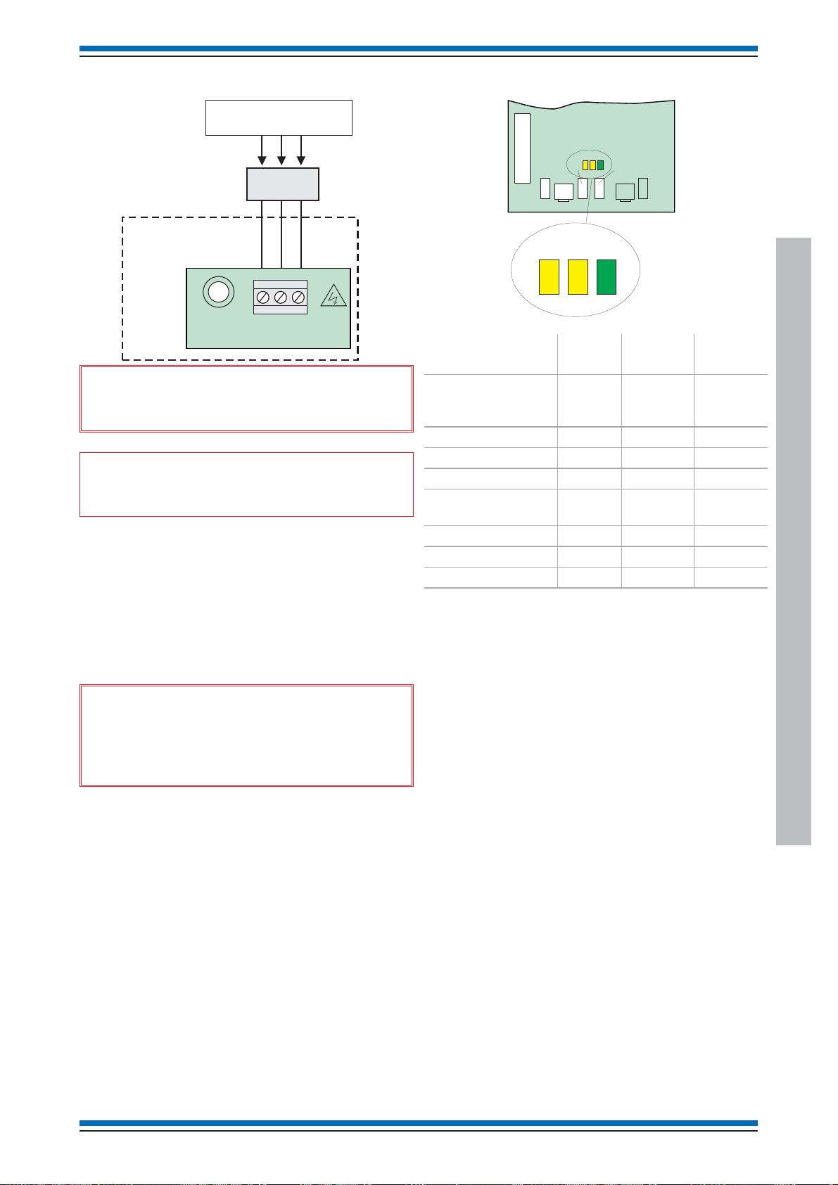
Vigilon (EN & BS) Compact (VA) panels
Mains supply
Dedicated mains supply
from consumer unit
5A Unswitched fused
spur unit
PANE L
E
N
L
P2
DANGER
&
FS3 3.15A(T)
Mains fuse
Ensure that the mains supply cable enters
the panel through a dedicated cable entry point.
"
designed to be powered from IT Power systems.
All mains powered equipment must be earthed. Mains supply to
any fire alarm control and indicating equipment must be via a
dedicated unswitched 5A fused spur unit, which should be clearly
labelled FIRE ALARM - DO NOT SWITCH OFF.
A disconnect device must be provided to disconnect both poles
and must have a minimum gap of 3mm. The Disconnect device
should be available as part of the building installation and must
be easily accessible after installation is complete.
These fire alarm system products are NOT
PSU Indicators
Y1 Y2 G1
Bat1 - FS1 - 3.15A
PSU BOARD
24V FS4 - 1A
P3
43V
FS6
1A
P7
BAT1
-
+
Y1 Y2 G1
Description Y1
(yellow)
Normal condition
(no faults in the
system)
Mains out of limit slow flash
24VDC failure only fast flash fast flash
Battery 1 failure only slow flash fast flash
Battery 1 and
24VDC failure
43VDC failure only fast flash fast flash
No power to PSU
Earth fault only On On On
Note on initial power up all three LEDs on the PSU will
switch on for approximately 1 second duration.
Y2
(yellow)
G1
(green)
fast flash
slow flash fast flash
&
Hazardous voltage remains after operation
of a protection fuse. Take appropriate action to
guard against the risk of equipment having exposed
live mains supply.
Vigilon Compact Panel
4188-856_i2_12/06_Generic Vigilon (Compact + VA) Comms. 29
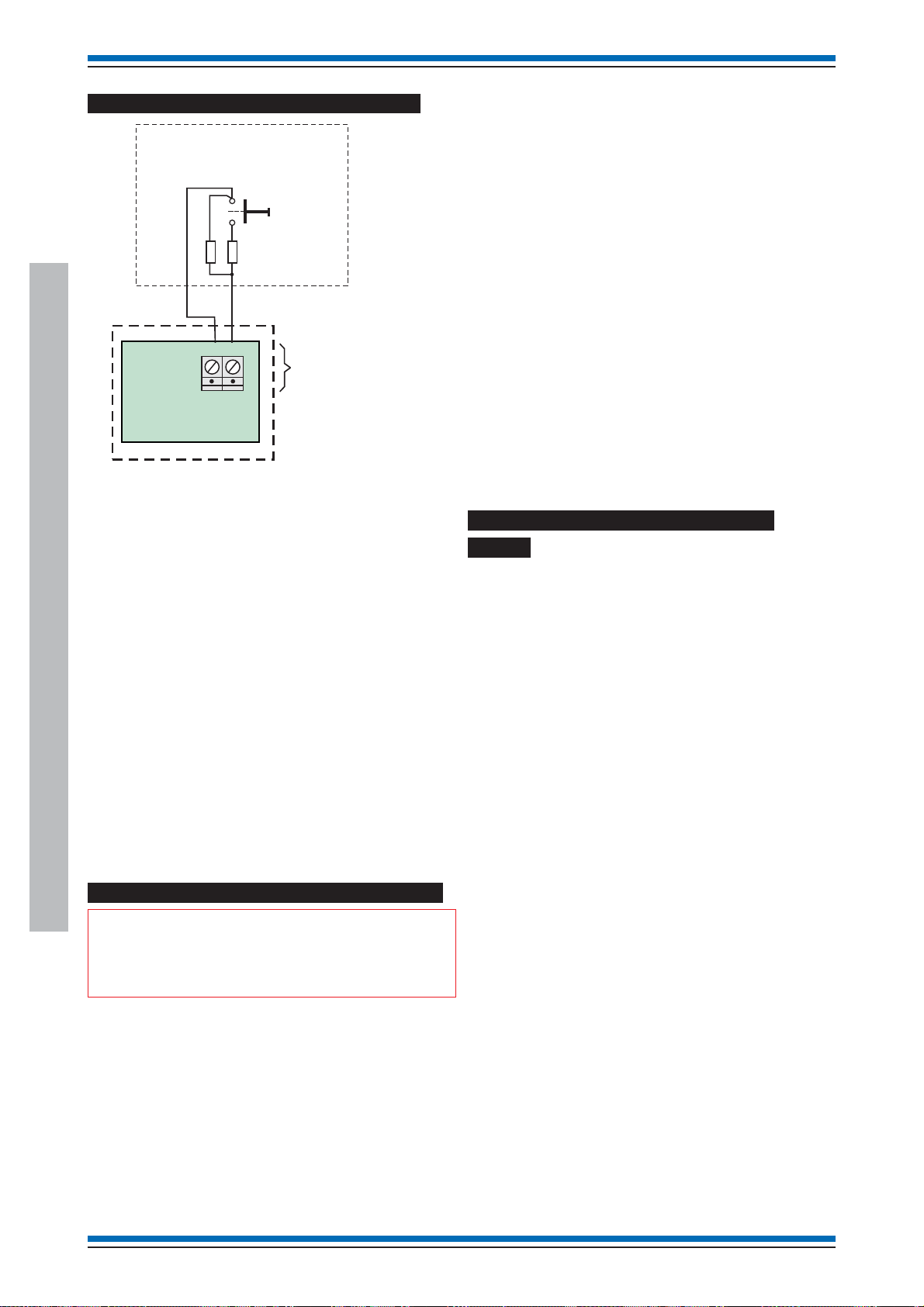
Generic Commissioning instructions
How to configure the monitored input
Normally open contacts
These contacts can be a push button
switch, fire relay contacts from another
panel or contacts from a timer.
2 - 10K Ohms resistors must be
fitted as shown.
0V
MIP
P8
Monitored Input
MASTER CONTROL
BOARD
PAN EL
The monitored input at the fire panel is activated by an external
switch installed maximum of 100m cable distance away from the
fire panel. The input is monitored for both short and open circuit
faults. When the input is active it triggers command build number
250 of the fire panel.
An active input will trigger
the command build No 250
The command build action
is configured
during commissioning
Press Menu On/Off button and select [SetUp], momentarily
press <etc> to select [SetUp] -> [Build] and type in the
command build number 251, select [Action] -> [Start MA] ->
[Enter] -> [Non Reversbl] -> [Enter]. The U1 button is now
configured to start the master alarm sounders.
Example 2
This example shows how to configure the U1 button such that it
operates an output of an interface unit and releasing the U1
button it returns the output to normal condition.
The following procedures assume a password entry is not
required.
Press Menu On/Off button and select [SetUp], momentarily
press <etc> to select [SetUp] -> [Build] and type in the
command build number 251, select [Action] -> [Usercode] and
momentarily press <etc> to select -> [Digital] and type in the
interface output channel number, select [On] and type in the
interface device number, select [Loop] and type in the loop
number -> [Enter], now select [Reversb] and then [Enter]. The
U1 button is now configured to switch on the digital output on an
interface unit and on releasing it will switch off the output.
How to configure LEDs CB253 and
CB254
Example
The following example shows how to configure the monitored
input at the panel to provide an output sound signal 1 alarms in
sector 2 of loop 1 as a reversible action. This means on operating
or "closing" the monitored input the panel will start alarms in
sector 1 and on releasing or "opening" the monitored input the
panel will stop the alarms.
The following procedures assume a password entry is not
required.
Press Menu On/Off button and select [SetUp] , momentarily
press <etc> to select [SetUp] -> [Build] and type in the
command build number 250, select [Action] -> [UserCode],
momentarily press <etc> to select [Sector], type in 2 for sector 2
and select [Loop] and type in 1 for Loop 1 -> [Action] -> [Signal
1] -> [Enter] -> [reversb] -> [Enter].
How to configure the buttons U1 and U2
Vigilon Compact Panel
"
level 2, that is access to the buttons is possible by
opening the panel door.
On operating the U1 or U2 at the panel it will cause triggering of
command build number 251 (for button U1) or command build
number 252 (for button U2). During commissioning the required
command build action must be configured.
Example
This example shows how to configure the U1 button such that
pressing it will start the master alarm sounders and pressing
Silence alarm button will stop the sounders.
The following procedures assume a password entry is not
required.
The U1 and U2 buttons are active at access
The switching of the LEDs CB253 and CB254 result from
actioning on command builds 253 and 254 respectively. The
switching action must be configured during commissioning.
This example shows how to configure the panel such that by
activating an interface input (can be a push button switch), it will
cause the panel LED - CB253 and Master alarms to switch On.If
the interface input is released then the panel LED-CB253 and
Master alarms will switch Off.
The following procedures assume a password entry is not
required.
Example:
Press Menu On/Off button and select [SetUp] , momentarily
press <etc> to select [SetUp] -> [Build] and type in the
command build number 253, select [Trigger] -> [IO line] and
type in the interface input channel number, select [Device] and
type in the interface device number, select [Loop] and type in
the loop number -> [Enter]. The command build 253 is now
configured to be triggered by the interface input.
Now to configure the command build label:
Press Menu On/Off button and select [SetUp], momentarily
press <etc> to select [SetUp] -> [Build] and type in the
command build number 253, select [Label] and enter a label of
up to 40 character in length, select either [Display] to display the
label on the panel when the command build 253 is triggered.
Now to setup the action of command build 253:
Press Menu On/Off button and select [SetUp], momentarily
press <etc> to select [SetUp] -> [Build] and type in the
command build number 253, select [Actionl -> [Start MA] ->
[Enter] -> [Reversbl] and [Enter].
30 4188-856_i2_12/06_Generic Vigilon (Compact + VA) Comms.
 Loading...