

Honeywell System 800, Gent System 800 Operator's Manual
by Honeywell
Operator’s Manual & Log book
System 800
Fire Alarm Panel

2 796689 (4188-658) i2_04/07
Table of Contents
Scope 4
General description 5
User responsibility 6
Daily 6
Weekly 6
Quarterly 7
Battery replacement 7
Controls and indicators 8
Navigation 8
Access levels 9
To enter access level 2 9
To return to access level 1 10
Normal Condition 11
To conduct a display test 11
Fire condition 12
To verify fire 13
To cancel buzzer 13
To silence alarms 13
To reset the system 13
Manual control of fire alarms 14
To sound alarms 14
To silence alarms 14
To operate delay mode 15
Fire Test 16
To enter fire test mode 16
To exit Fire test mode 17
Fault condition 18
To Cancel buzzer 18
Disablement condition 20
Typical disablement 20
System information 21
To view active fire events 21
To view active fault events 21
To view active disablement 22
To view historic events 22

796689 (4188-658) i2__04/07 3
System set up 23
Hardware link 23
To enable or disable a zone 24
To edit a zone label 25
To put a zone in and out of test mode 26
To view devices in a zone 27
To enable or disable a device 28
To edit a device label 29
To enable or disable alarm sounders 30
To set up weekly reminder of fire test 31
To set up the Initial and Verify delay 32
Other controls 33
Loop status 33
Local input 33
Loop map 33
Auxiliary relay 34
Fire routing output 34
Fault routing output 34
Maintenance reminder 34
Appendix 35
Glossary of terms 35
Description of Controls and Indicators36
Controls at the system 800 panel 37
Indicators at the system 800 panel 38
Menu 43
Controls and indicators 43
4 796689 (4188-658) i2_04/07
Scope
Safety
Associated documents
This second issue of the Operator’s manual
covers the operating instructions for the
24-zone system 800 fire alarm panel. The
manual shows how to operate controls and
interpret light indications and messages. It
includes information on user responsibility
and emergency conditions with step by step
instructions on how to operate controls. The
manual has also a log book with pages to
record system events for future reference.
The following information is given in the
interest of personal safety and to prevent
damage to equipment installed and to
ensure the system operates correctly.
The information symbol is
accompanied with important text.
This can be either a warning to
prevent personal injury or death, or
a caution to prevent damage to the
system equipment.
Installer’s manual 796688 (4188-657)
All the documents associated with the panel
should be kept together near the panel.
Issue Record
Issue Date Comment
1 11/12/00 This is the first issue of the operating manual.
1-1 06/02/01 Minor updates to improve instructions.
2 10/06/03 This is the second update to the installer’s manual include
coincidence detection, sector linking, improvements to the
settings for delay mode and auxiliary relay configuration.
23/04/07 Gent by Honeywell logo added

796689 (4188-658) i2__04/07 5
General description
The system 800 fire alarm panel is designed
to meet the requirements of EN54 Parts 2
and 4. It is suitable for installation in small to
medium size buildings in accordance with
the recommendations of BS5839:Part 1, to
provide an automatic fire detection and
alarm.
The system 800 panel is installed and
configured to monitor devices such as
detectors, manual call points and sounder
control transponder units connected on a
single loop. Each device is capable of being
addressed individually and may be assigned
to one of 24 zones. The devices and zones
in the system can each be given a label for
identification. In the event of a fire the panel
automatically operates external sounder
circuits to raise an alarm in the protected
buildings.
The push button controls on the panel are
for use by authorised and trained personal.
To comply with the requirements of
BS5839:Part 1, there are log sheets
provided at the back of this manual for
recording system events.

6 796689 (4188-658) i2_04/07
User
responsibility
Daily
Weekly
It is recommended that the persons
responsible for the fire alarm system should
become familiar with:
How to operate the controls
How to interpret visual indications given.
BS 5839:Part 1, states that the system
should be inspected daily to ensure that a
normal indication is given at the control and
indicating equipment and:
any previously indicated fault and
warning condition has received
appropriate attention.
all the system events are entered into
the Log Book for future reference.
the use of the area(s) inspected has not
changed since the system was
designed.
and no unsafe practices that could lead
to a fire are being undertaken.
At weekly interval:
a different Fire Sensor or Manual Call
Point of the system should be tested to
ensure the system is capable of
operating under alarm condition.
the operation of the alarm sounders
should be checked to also remind those
occupying the premises that there is a
fire alarm system with a particular
sound.
The test should be performed at a
regular time to avoid confusion
between a test and a genuine fire
alarm.

796689 (4188-658) i2__04/07 7
Quarterly
Battery replacement
At quarterly intervals the fire alarm system
should be inspected by the servicing
organisation. A trained maintenance
engineer from the servicing organisation
should carry out any work necessary.
For help with service and
maintenance contact your
Servicing organisation, see log
book.
Every four years the batteries installed in the
system 800 panel must be replaced.
CAUTION:
RISK OF EXPLOSION IF
BATTERY IS REPLACED BY AN
INCORRECT TYPE.
DISPOSE OF USED BATTERIES
ACCORDING TO THE
INSTRUCTIONS.
8 796689 (4188-658) i2_04/07
Controls and
indicators
Audible
indication
While reading the instructions it may help to
open out the back page of this manual to
view the location of controls and indicators
on the panel. For description of controls and
indicators see User controls and indicators
section.
There is a cancellable buzzer in the panel
that operates automatically to announce Fire
and Fault events.
Navigation
Previous
Next
Esc
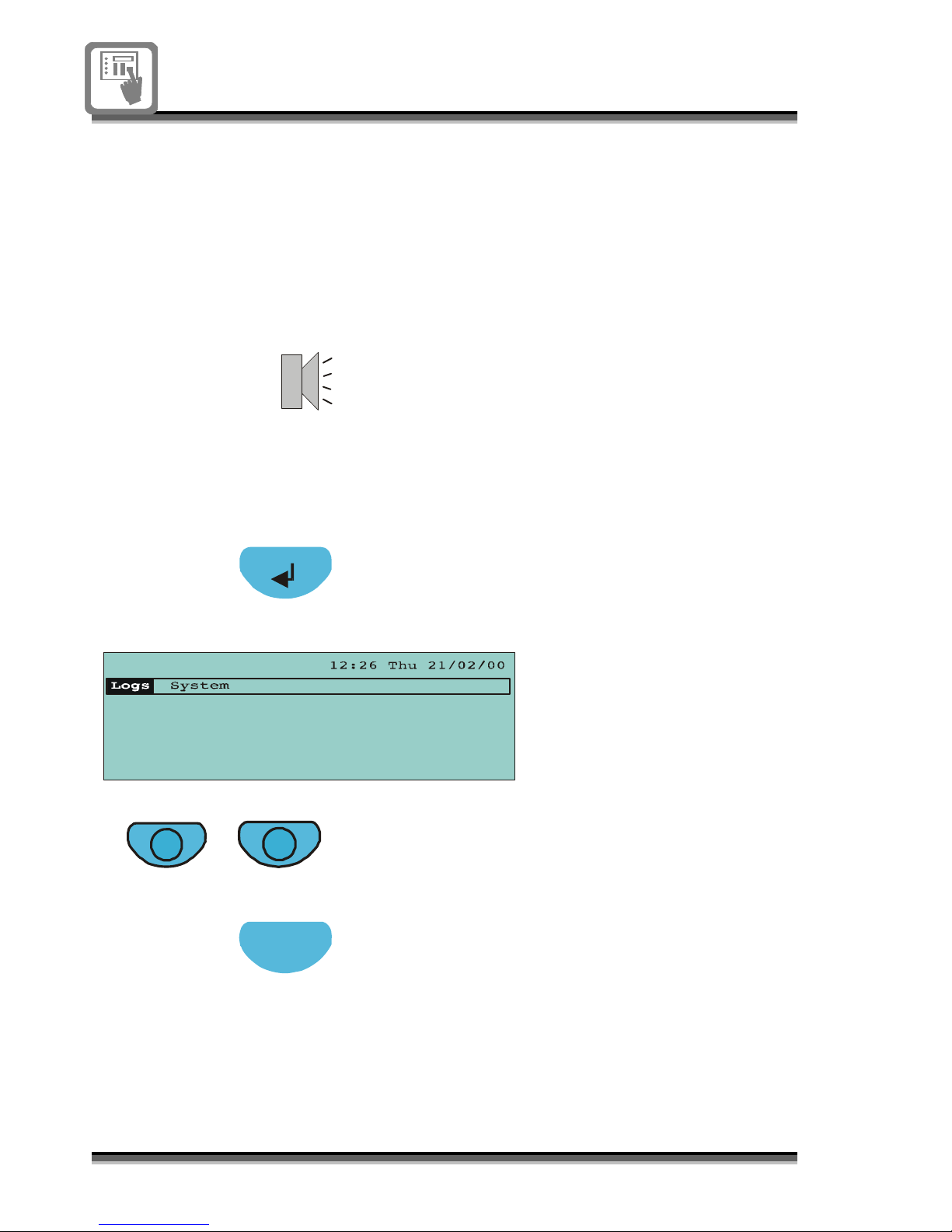
The buttons to navigate the menu and to
select a menu option at the panel are the
Enter, Previous, Next and Esc buttons.
The Enter button will display the top-level
menu or accept a selection.
The menu bar displayed
here shows the menu
available at access level 1.
The Previous and Next buttons can be used
to scroll and select a menu option.
The Esc button performs a quit function.
Pressing the Esc button will close an open
menu or sub-menu and return it to the
previous display.
796689 (4188-658) i2__04/07 9
Access levels
Access level 1 (A1)
Access level 2
(A2)
To enter access
level 2
The instructions in this manual are for
access to menu options and push button
controls available at access levels 1 and 2.
Access level 1 is for the general public and
requires no coded entry, and at this level the
light indications of the panel are visible,
along with menu options to view logs and
gain coded entry to level 2.
Access level 2 is for authorised persons who
are responsible for the fire alarm, such as
security staff. This level requires a coded
entry to the panel’s push button controls and
menu options. If controls are not used for 3
minutes duration then access level 2 is
automatically exited.
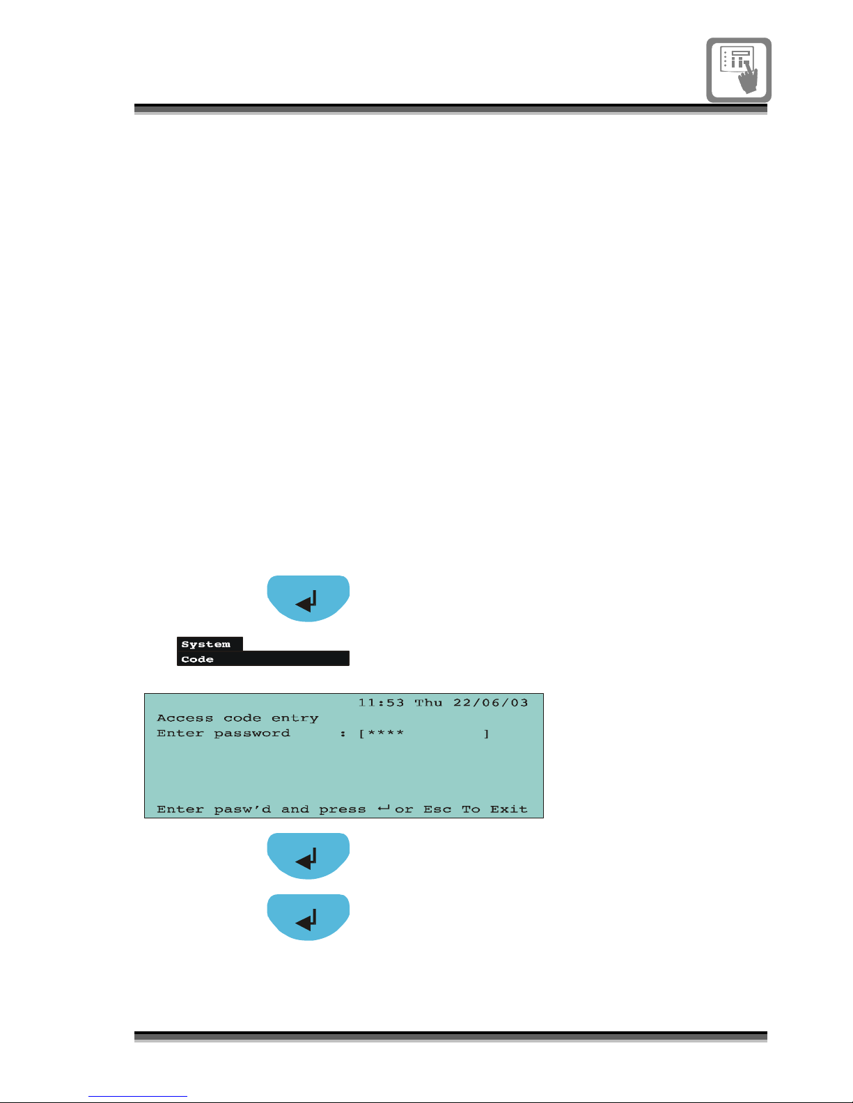
Press the Enter button to display the
menu bar.
Select System menu and option Code,
and then press the Enter button to
display the Access code entry form.
Enter the numerical
access code for
level 2 controls and
menu options. An
asterisk will appear
on the display for
every number entry.
Press Enter to accept the code.
The factory set codes for:
Access level 1 – None
Access level 2 - 2222
An acknowledgement is given of correct
code entry.
10 796689 (4188-658) i2_04/07
To return to access
level 1
Esc
Alternative method
Previous
Next
To exit access level 2 and return to access
level 1.
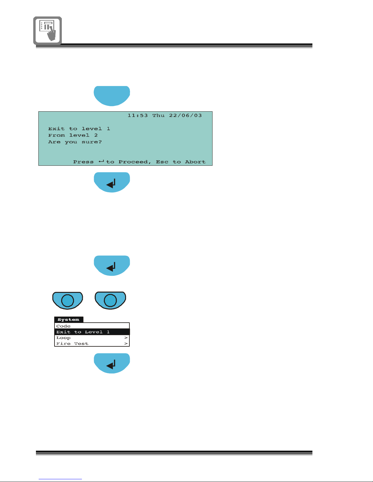
Press the Esc button to exit to level 1.
Press Enter to accept a return to level 1
and the display will respond with the
access level changed message.
Press the Enter button to display the top-
level menu.
Press the Previous or Next button to
‘System’ option and scroll through the
menus to highlight Exit to level 1 option.
Press Enter to exit to access level 1.
796689 (4188-658) i2__04/07 11
Normal
Condition
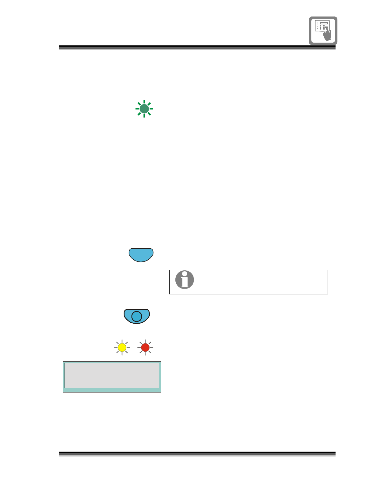
Power
The green LED is normally lit giving a steady
to indicate that mains and battery supply to
the panel are healthy.
To conduct a display
test
A2
Esc
Display Test
The panel lights and display can be tested to
check that they are working.
The Display Test is factory set to operate at
access level 2.
Enter access level 2.
Press the Esc key to exit the menu
screen.
The display test can only operate if
the default screen is displayed.
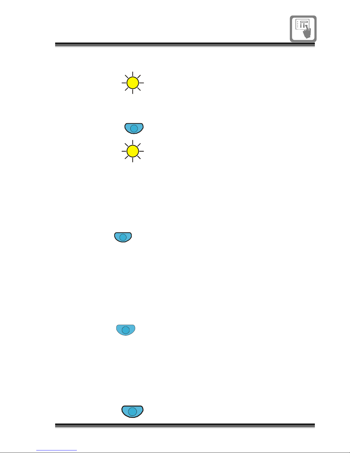
Press the Display Test button.
All the light indicators are lit on the panel
and will remain lit for a short duration.
The display pixels are also tested.

12 796689 (4188-658) i2_04/07
Fire condition
Fire
Fire Routing
Activated
Fire Protection
Activated
Fire event(s) from detectors or manual call
points in zone(s) are indicated and logged at
the panel.
The red Fire light is lit.
The first fire information is given in the top
portion of the display, while the latest fire in
the lower portion.
The local buzzer sounds to announce each
fire event.
If the facilities are available and configured
for use, then the Fire Routing and Fire
Protection lights are lit
.
System alarm sounders are active.
Follow site evacuation procedures.
Number of
active fires
First fire:
Zone number
Device or location label
Latest fire
Device of location label
First fire:
device number
Number of
zones in fire
796689 (4188-658) i2__04/07 13
To verify fire
Delay
A2
Veri fy
Verification
If delay mode is ON, that is if the Delay light is
lit, the alarm sounders are inactive for a 30
seconds (factory set) duration. During this
time the alarm delay can be extended by a
pre-configured time (up to 10 minutes
maximum) by operating the Verify button.
Enter access level 2.
Press the Verify button.
The verification light is lit to show the fire
alarm delay has been extended.
NOTE: Operating Sound Alarms button or
if there is a subsequent fire event the
alarms are activated immediately.
To cancel buzzer
Cancel Buzzer
To silence the panel buzzer while the
system is in fire condition:
Press the Cancel Buzzer button.
To silence alarms
A2
Silence Alarms
To stop the fire alarm sounders from
sounding, for example once the building has
been evacuated and the fire fighters are
present to attend to the fire.
Enter access level 2.
Press the Silence Alarms button.
To reset the system
A2
Reset
After the emergency is over and the affected
devices have been restored for normal
operation and alarms have been silenced:
Enter access level 2
Press the Reset button.
14 796689 (4188-658) i2_04/07
Manual control
of fire alarms
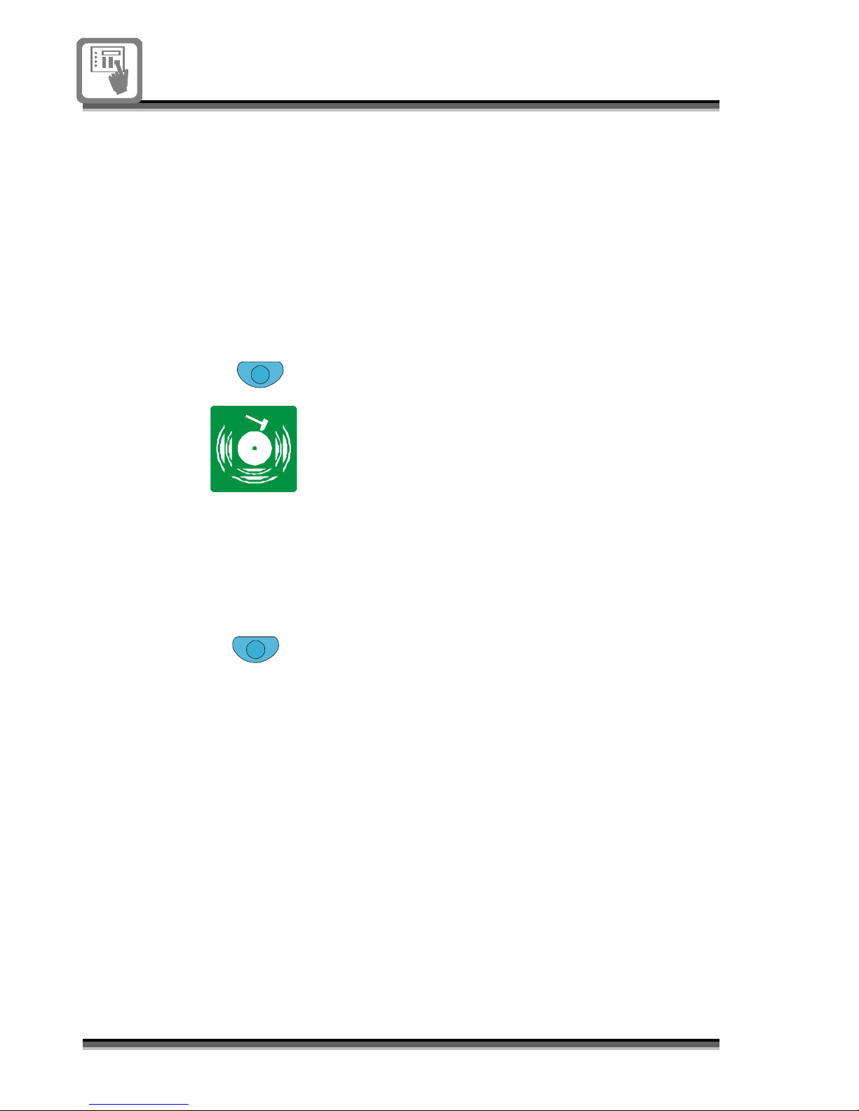
To sound alarms
A2
Sound Alarms
To manually sound alarms in the system at
anytime or resound the alarms after they
have been silenced:
Enter access level 2.
Press the Sound Alarms button.
Note the alarms are sounding!
To silence alarms
A2
Silence Alarms
To stop the alarms from sounding:
Enter access level 2.
Press the Silence Alarms button.
Note the alarms are silenced!
 Loading...